JP6173093B2 - Winding device and winding method - Google Patents
Winding device and winding method Download PDFInfo
- Publication number
- JP6173093B2 JP6173093B2 JP2013156209A JP2013156209A JP6173093B2 JP 6173093 B2 JP6173093 B2 JP 6173093B2 JP 2013156209 A JP2013156209 A JP 2013156209A JP 2013156209 A JP2013156209 A JP 2013156209A JP 6173093 B2 JP6173093 B2 JP 6173093B2
- Authority
- JP
- Japan
- Prior art keywords
- wire
- winding
- nozzles
- wire rod
- cutting
- Prior art date
- Legal status (The legal status is an assumption and is not a legal conclusion. Google has not performed a legal analysis and makes no representation as to the accuracy of the status listed.)
- Active
Links
Images


Classifications
-
- H—ELECTRICITY
- H02—GENERATION; CONVERSION OR DISTRIBUTION OF ELECTRIC POWER
- H02K—DYNAMO-ELECTRIC MACHINES
- H02K15/00—Methods or apparatus specially adapted for manufacturing, assembling, maintaining or repairing of dynamo-electric machines
- H02K15/08—Forming windings by laying conductors into or around core parts
- H02K15/09—Forming windings by laying conductors into or around core parts by laying conductors into slotted rotors
-
- H—ELECTRICITY
- H02—GENERATION; CONVERSION OR DISTRIBUTION OF ELECTRIC POWER
- H02K—DYNAMO-ELECTRIC MACHINES
- H02K15/00—Methods or apparatus specially adapted for manufacturing, assembling, maintaining or repairing of dynamo-electric machines
- H02K15/08—Forming windings by laying conductors into or around core parts
- H02K15/085—Forming windings by laying conductors into or around core parts by laying conductors into slotted stators
Description
本発明は、巻線されるティースの個数と同じ数だけの複数のノズルを有する巻線装置及びその複数のノズルから各ティース間のスロットにそれぞれ線材を同時に繰出して、各ノズルに対応する所定の2つのスロットの間にそれぞれ同時に線材を巻線する巻線方法に関するものである。 The present invention provides a winding device having a plurality of nozzles of the same number as the number of teeth to be wound, and a wire rod that is simultaneously fed from each of the plurality of nozzles to a slot between the teeth, and a predetermined number corresponding to each nozzle. The present invention relates to a winding method in which a wire is wound between two slots at the same time.
従来、例えば、車両等に搭載されるモータとしては、ブラシレスモータがある。このブラシレスモータは、モータハウジングに内嵌固定されているステータと、ステータの径方向内側に回転自在に設けられたロータとを有している。このステータやロータには、放射状に突設された複数のティースが形成され、各ティース間には、径方向内側や外側に開口するスロットがそれぞれ形成される。そしてこれらスロットを介して、複数のティースに集中巻方式や分布巻方式によって線材が巻線されるようになっている。 Conventionally, for example, there is a brushless motor as a motor mounted on a vehicle or the like. The brushless motor includes a stator that is fitted and fixed to a motor housing, and a rotor that is rotatably provided on the radially inner side of the stator. The stator and the rotor are formed with a plurality of radially projecting teeth, and slots are formed between the teeth so as to open radially inward and outward. Through these slots, a wire is wound around a plurality of teeth by a concentrated winding method or a distributed winding method.
ところで、モータの高効率化や小型化などを図るためには、巻線の占積率を向上させることが有効である。とりわけ、巻線は2つのスロットの間に行われるものであるので、この巻線は、一方のスロットルに線材を挿入した後、その線材を折り返して他方のスロットルに再び線材を挿入することになる。すると一方のスロットルから他方のスロットルに渡る渡り線が膨らむと、その小型化は困難となる。 By the way, in order to increase the efficiency and miniaturization of the motor, it is effective to improve the space factor of the winding. In particular, since the winding is performed between two slots, the wire is inserted into one throttle, and then the wire is folded and the wire is inserted again into the other throttle. . Then, when the crossover from one throttle to the other throttle swells, it becomes difficult to reduce the size.
そこで、巻線されるティースの個数と同じ数だけの複数のノズルを放射状に設け、その複数のノズルから各ティース間のスロットにそれぞれ線材を同時に繰出して、各ノズルに対応する所定の2つのスロットの間にそれぞれ同時に線材を巻線する技術が提案されている(例えば、特許文献1参照)。 Therefore, a plurality of nozzles of the same number as the number of teeth to be wound are provided radially, and wire is fed from the plurality of nozzles to the slots between the teeth at the same time, and predetermined two slots corresponding to the nozzles. A technique has been proposed in which a wire is wound at the same time (see, for example, Patent Document 1).
この技術では、複数のノズルから同時に線材が繰出されるので、渡り線を形成するにあたって、複数のノズルが径方向内側へと移動すると、各渡り線が径方向内側へと押さえつけられ、互いに徐々に径方向内側に変位しながら絡み合った状態になる。このようにすることで、渡り線が膨らむようなことは防止され、巻線の占積率を向上させ得るとしている。 In this technique, since the wire rods are fed out simultaneously from a plurality of nozzles, when the plurality of nozzles move inward in the radial direction when forming the crossover wires, the connecting wires are pressed down inward in the radial direction, and gradually move toward each other. It becomes intertwined while being displaced radially inward. By doing in this way, it is said that it is prevented that a jumper wire swells and the space factor of a coil | winding can be improved.
しかしながら、上述の従来技術にあっては、ティースの個数と同じ数だけの複数のノズルを設け、その複数のノズルから各ティース間のスロットにそれぞれ線材を同時に繰出しているので、そのノズルに線材を供給する線材供給源もそのノズルの数だけ必要になる。ここで、一般的に線材はスプールに巻回された状態で蓄えられ、そのスプールから線材を解きほぐすことにより供給可能となり、巻線するためにはスプールから操出された線材を真っ直ぐにする必要もある。このため、線材供給源は、少なくとも線材が巻回されたスプールと、その線材を真っ直ぐに伸ばす伸張機を必要とする。よって、このように線材が巻回されたスプールや伸張機をノズルの数だけ準備してノズルの周囲に配置するので、装置が大型化する不具合があった。 However, in the above-described prior art, the same number of nozzles as the number of teeth are provided, and the wire rods are simultaneously fed from the plurality of nozzles to the slots between the teeth. As many wire supply sources as the number of nozzles are required. Here, the wire is generally stored in a state of being wound around a spool, can be supplied by unwinding the wire from the spool, and it is also necessary to straighten the wire operated from the spool for winding. is there. For this reason, the wire supply source requires at least a spool around which the wire is wound and a stretcher that extends the wire straightly. Therefore, since the spools and stretching machines around which the wire is wound are prepared as many as the number of nozzles and arranged around the nozzles, there is a problem that the apparatus becomes large.
特に、出力が比較的大きなモータに使用されるステータやロータに形成されるティースの数は、20本を超えるものが多い。このため、そのようなステータやロータに巻線するために、20個以上のスプールや伸張機を準備して、それらを20本以上もあるノズルの周囲に配置することは、巻線装置自体が著しく大型化して、比較的広い設置場所を必要とする不具合がある。 In particular, the number of teeth formed on a stator or rotor used in a motor with a relatively large output often exceeds 20. For this reason, in order to wind around such a stator or rotor, it is necessary for the winding device itself to prepare 20 or more spools or stretching machines and arrange them around 20 or more nozzles. There is a problem that the size is remarkably increased and a relatively large installation place is required.
本発明の目的は、複数のノズルを設けるにも係わらず、スプールや伸張機の数を減らして小型化し、広い設置場所を不要とし得る巻線装置及び巻線方法を提供することにある。 An object of the present invention is to provide a winding device and a winding method that can be reduced in size by reducing the number of spools and expansion machines, and can eliminate the need for a wide installation place, despite the provision of a plurality of nozzles.
本発明は、ティースの個数と同じ数だけのノズルが放射状に設けられ、複数のノズルから各ティース間のスロットにそれぞれ線材を同時に繰出して、各ノズルに対応する所定の2つのスロットの間に、それぞれ同時に線材を巻線する巻線装置の改良である。 In the present invention, the same number of nozzles as the number of teeth are provided in a radial manner, and a wire rod is simultaneously fed from a plurality of nozzles to slots between each tooth, and between two predetermined slots corresponding to each nozzle, It is an improvement of a winding device that winds a wire at the same time.
その特徴ある構成は、単一のスプールから繰出された線材を所定の長さで操出して切断する線材操出し切断手段と、線材操出し切断手段により得られた所定長さの線材を複数のノズルの数と同じ数まで集めて放射状に配置する蓄線手段と、放射状に配置された複数の線材を蓄線手段から複数のノズルにまで案内する線材運搬手段とを備えたところにある。 The characteristic configuration is that a wire rod fed out from a single spool is steered at a predetermined length and cut, and a wire rod of a predetermined length obtained by the wire rod feeding and cutting means is a plurality of wires. There are storage means for collecting and arranging the same number as the number of nozzles radially, and wire conveying means for guiding the plurality of radially arranged wires from the storage means to the plurality of nozzles.
この巻線装置では、線材操出し切断手段が複数設けられ、蓄線手段は複数の線材操出し切断手段により得られた所定長さの線材をノズルの数と同じ数まで集めて放射状に配置するように構成されることが好ましく、線材が被覆導線である場合には、操出される線材の被覆を除去する被覆除去装置を線材操出し切断手段に設けることもできる。 In this winding device, a plurality of wire material cutting and cutting means are provided, and the wire storage means collects the wire rods of a predetermined length obtained by the plurality of wire material cutting and cutting devices to the same number as the number of nozzles and arranges them radially. Preferably, when the wire is a coated conductor, a coating removal device that removes the coating of the wire to be driven out can be provided in the wire feeding and cutting means.
別の本発明は、ティースの個数と同じ数だけ放射状に設けられた複数のノズルから各ティース間のスロットにそれぞれ線材を同時に繰出して、各ノズルに対応する所定の2つのスロットの間にそれぞれ同時に線材を巻線する巻線方法の改良である。 According to another aspect of the present invention, a wire rod is simultaneously fed from a plurality of nozzles provided in the same number as the number of teeth to slots between the teeth, and simultaneously between two predetermined slots corresponding to the nozzles. This is an improvement of a winding method for winding a wire.
その特徴ある点は、線材を巻線している間に単一のスプールから繰出されて巻線に必要な所定長さに切断された線材を複数のノズルの数と同じ数まで集めて放射状に配置する蓄線工程が行われ、線材の巻線の後に、放射状に配置された複数のノズルの個数と同じ数の所定長さの線材を複数のノズルにまで案内する線材運搬工程が行われるところにある。
The characteristic point is that the wire rods, which are fed from a single spool and wound to a predetermined length necessary for winding while winding the wire rods, are gathered up to the same number as a plurality of nozzles to be radial. The wire storage process to be arranged is performed, and after the winding of the wire, the wire conveying process is performed to guide the wire of the predetermined length as many as the plurality of nozzles arranged radially to the plurality of nozzles. It is in.
本発明の巻線装置及び巻線方法では、単一のスプールから繰出された線材を所定の長さで操出して切断する線材操出切断手段を備え、それにより得られた複数の線材を線材運搬手段により複数のノズルにまで案内するので、ノズルの数に等しい数のスプールや伸張機を必要としない。よって、ノズルの数に等しい数のスプールや伸張機を必要としていた従来に比較して、装置は小型になり、広い設置場所を不要とすることができる。 In the winding device and winding method of the present invention, wire winding and cutting means for driving and cutting a wire fed from a single spool by a predetermined length is provided, and the plurality of wires obtained thereby are wire rods. Since the conveying means guides to a plurality of nozzles, the number of spools and stretching machines equal to the number of nozzles are not required. Therefore, compared to the conventional case where the number of spools and expansion machines equal to the number of nozzles are required, the apparatus becomes smaller and a large installation place can be eliminated.
線材操出切断手段を複数設け、蓄線手段は複数の線材操出切断手段により得られた所定長さの線材をノズルの数と同じ数まで集めて放射状に配置するようにすれば、巻線工程に係る時間内において、ノズルの数に等しい数の所定長さの線材を確実に準備することが可能となる。この場合であっても、線材操出切断手段の数をノズルの数未満とすることにより、装置は小型になり、広い設置場所を必要とすることはない。また、蓄線手段を備えることにより、巻線工程と同時に蓄線工程を行うことで、生産性を向上させることができる。 If a plurality of wire rod cutting and cutting means are provided, and the wire storage means collects wire rods of a predetermined length obtained by the plurality of wire rod cutting and cutting devices to the same number as the number of nozzles and arranges them radially, winding Within the time relating to the process, it is possible to reliably prepare a wire having a predetermined length equal to the number of nozzles. Even in this case, by making the number of wire material cutting and cutting means less than the number of nozzles, the apparatus becomes small and does not require a wide installation place. In addition, by providing the storage means, productivity can be improved by performing the storage process simultaneously with the winding process.
線材操出切断手段によって線材を操出す際に、その後に線材の接続されることになる部位の被覆を被覆除去装置により除去するようにすれば、その後の線材の接続作業を比較的容易に行うことが可能になる。 When the wire rod is manipulated by the wire rod feeding / cutting means, if the coating of the portion to which the wire rod is to be connected thereafter is removed by the coating removing device, the subsequent wire rod connecting operation is relatively easy. It becomes possible.
次に、本発明を実施するための最良の形態を図面に基づいて説明する。 Next, the best mode for carrying out the present invention will be described with reference to the drawings.
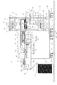
図1〜図11に、本発明の巻線装置20を示す。この実施の形態における巻線装置20は、巻線の対象がモータに使用されるロータである場合を示す。
1 to 11 show a
図12〜図14に示すように、このロータ10は、放射状に突設された複数のティース11を有しており、各ティース11間には、径方向外側に開口するスロット12がそれぞれ形成される。そして、巻線装置20は、これらスロット12を介して、複数のティース11に線材16を実際に巻線させる巻線手段21と、線材操出切断手段61と、蓄線手段71と、線材運搬手段81を有する。
As shown in FIGS. 12 to 14, the
図1、図5〜図7に示すように、巻線装置20における巻線手段21は、巻線対象とするロータ10のティース11の個数と同じ数だけのノズル22を備える。この実施の形態では、巻線対象とするロータ10は20個以上のティース11が放射状に設けられたものである場合を示す。これにより、巻線手段21は20本以上の放射状に設けられたノズル22を備える。
As shown in FIGS. 1 and 5 to 7, the winding means 21 in the
巻線手段21におけるノズル22は水平な水平基板23を介して放射状に配置され、その水平基板23は4本の支柱24を介して浮上して支持される。4本の支柱24は台板26に立設され、この台板26には巻線手段21を移動させるためのローラ27とその移動を禁止する支持脚28が設けられる。
The
図7に示すように、水平基板23の略中央には、巻線対象とするロータ10が通過可能な中央孔23aが形成され、その中央孔23aを包囲するリング部材29が水平基板23上に設けられ、リング部材29には水平基板23と平行なドーナツ状の取付円板31が取付けられる。この取付円板31の中央には、水平基板23の中央孔23aと同軸の丸孔31aが形成され、複数のノズル22はこの丸孔31aを中心として放射状に取付円板31上に設けられる。
As shown in FIG. 7, a
取付円板31には、先ずレール32が放射状に設けられ、それらのレール32には移動台33が移動可能に設けられる。
First, rails 32 are radially provided on the mounting
移動台33は、丸孔31aを中心に放射状を成すように細長く形成され、その内端部33aにノズル22が設けられる。また移動台33の外端部には、ノズル22に先端が挿通された線材16の中間又は基端側を支持する支持部33bが形成される。
The moving table 33 is formed in an elongated shape so as to form a radial shape around the
リング部材29の外周にはカム板34が嵌入され、カム板34は取付円板31の丸孔31aを中心に水平面内において回転可能に構成される。移動台33の外周側における支持部33bには、その下端から下方に延びるカムフォロア33cが設けられ、カム板34にはそのカムフォロア33cが進入するカム溝34aが形成される。図5に示すように、カム板34に形成されるカム溝34aは、丸孔31aを中心に周方向にノズル22の数と同じ数だけ等角度に形成される。
A
図7に戻って、カム板34には丸孔31aを中心とする平ギヤ34bが設けられ、この平ギヤ34bに歯合して、その平ギヤ34bとともにカム板34を回転させるノズル駆動モータ36が水平基板23に設けられる。そして、このノズル駆動モータ36によりカム板34が回転すると、カム溝34aに進入したカムフォロア33cがそのカム溝34aに沿って移動し、放射状に設けられた複数の移動台33を同時に内側又は外側に移動させるように構成される。
Returning to FIG. 7, the
ここで、各移動台33に対応して水平基板23に設けられた、図7の符号で示す37は、線材16の有無を検出するセンサ37である。また、水平基板23の下面に設けられた、図7の符号で示す38は、線材16が巻線されたロータ10の端子装着部をかしめるかしめ部材38であって、図7の符号で示す39は、そのかしめ部材を稼動させるかしめ用モータ39である。
Here,
図1、図6及び図7に示すように、この巻線手段21は、巻線対象とするロータ10を複数のノズル22により囲まれる丸孔31aの下方にまで搬送するロータ搬送手段40と、搬送されたロータ10を昇降させるロータ昇降手段45と、それにより上昇したロータ10の上方を支持するとともに、線材16の巻き初め端部16a(図12及び図13)を咬持するロータ支持手段50を有する。
As shown in FIGS. 1, 6, and 7, the winding
ロータ昇降手段45は、取付円板31の丸孔31aの下方に鉛直方向に延びて設けられた昇降ロッド46と、その昇降ロッド46の下部を枢支して4本の支柱24に昇降可能に設けられた枢支昇降板47と、枢支昇降板47より下方の4本の支柱24に昇降不能に設けられた固定板44と、その固定板44に設けられてその枢支昇降板47を昇降ロッド46とともに昇降させるロッド昇降モータ48と、その昇降ロッド46を回転させる回動モータ49とを備える。
The rotor lifting / lowering means 45 can be lifted / lowered to the four
一方、ロータ搬送手段40は、ロータ10を支持可能な支持台41と、その支持台41が先端に取り外し可能に設けられた3本のアーム42を備え、そのアーム42は先端を外側にして放射状に設けられる。
On the other hand, the
固定板44にはこの3本のアーム42を回転させて、それぞれのアーム42の先端に設けられた支持台41にロータ10を搭載した状態で周方向に搬送する搬送モータ43が設けられ、搬送モータ43の回転軸43a上に3本のアーム42の基端が取付けられる。
The fixed
この3本のアーム42は水平基板23より下方の水平面内において回転することにより、そのうちの一方の先端の支持台41に支持されたロータ10は、取付円板31の丸孔31aの下方に位置し、この下方まで案内されたロータ10を、昇降手段における昇降ロッド46を上昇させると、昇降ロッド46の上端に支持台41が搭載され、その状態で昇降ロッド46が更に上昇することにより、支持台41とともに上昇するロータ10を丸孔31aに通過可能に構成される。
The three
ロータ支持手段50は、支柱24の上端に取付けられた固定台51と、その固定台51と水平基板23との間の支柱24に昇降可能に設けられた昇降台52と、その昇降台52に枢支されて丸孔31aを通過して上昇したロータ10の上部を上方から押さえる押さえ部材53と、固定台51に設けられてその昇降台52を昇降させる押さえ昇降モータ54と、その押さえ部材53を回転させる回転モータ55とを備える。
The rotor support means 50 includes a fixed
なお、図示しないが、押さえ部材53には、複数のノズル22から操出される全ての線材16の巻き初め端部16a(図12及び図13)を咬持する咬持機構が設けられる。
Although not shown, the holding
図1に示すように、本発明の巻線装置20は、単一のスプール17から繰出された線材16を所定の長さで操出して切断する線材操出切断手段61を備える。スプール17には線材16が巻回されて貯線され、このスプール17が線材16の供給源となる。
As shown in FIG. 1, the winding
この実施の形態における線材16は被覆導線であって、断面が円形を成すいわゆる丸線が用いられる。けれども、この線材16は断面が方形を成すいわゆる角線であっても良い。
The
そして、線材操出切断手段61は、この様の貯線されたスプール17と、そのスプール17から引き出された線材16を真っ直ぐにする伸張機62を備える。
The wire rod feeding and cutting means 61 includes a
巻線手段21における台板26の近傍には、その台板26に隣接して箱台60が設けられ、台板26の反対側における箱台60の近傍にスプール17が設置される。
A
そして、伸張機62は箱台60の上面からスプール17の上方に突出して設けられた鉛直板62aと、その鉛直板62aに設けられ、スプール17から上方に操出された線材16を巻線手段21に向けて水平方向に転向させる転向プーリ62bと、水平方向に転向した線材16を上下方向から挟んで、その上下方向の曲がりを正す鉛直方向矯正プーリ62cと、水平方向に転向した線材16を水平方向両側から挟んで、その水平方向の曲がりを正す水平方向矯正プーリ62dを備える。なお、この箱台60にも、これを移動させるためのローラ27とその移動を禁止する支持脚28が設けられる。
The
線材操出切断手段61は、伸張機62により巻線手段21方向に転向して真っ直ぐにされた線材16を把持するチャック機構63と、そのチャック機構63を伸張機62側から巻線手段21側へと移動させる線材移動アクチュエータ64と、線材移動アクチュエータ64の巻線手段21側端縁に設けられてエア圧によりその線材16を切断するニッパ装置65とを備える。
The wire material cutting and cutting means 61 includes a
線材移動アクチュエータ64は、伸張機62側から巻線手段21側へ延びるハウジング64aと、そのハウジング64a内部に長手方向に延びて設けられたネジ軸64bと、そのネジ軸64bに螺合してハウジング64aの長手方向に移動可能に設けられた可動台64cと、その搬送ネジ軸64bを回転させるサーボモータ64dとを有し、チャック機構63はその可動台64cに取付けられる。
The
チャック機構63は、可動台64cに取付けられた本体部63aと、その本体部63aから上方に突出して実際に線材16を把持する一対の把持片63b,63b(図2)を有し、線材移動アクチュエータ64のサーボモータ64dが駆動して搬送ネジ軸64bが回転すると、それに螺合する可動台64cがネジ軸64bの長手方向に移動して、その可動台64cとともに移動するチャック機構63が線材16を把持することにより、線材16をその移動量だけ操出すように構成される。
The
そして、線材移動アクチュエータ64の巻線手段21側端縁に設けられたニッパ装置65はエア圧により閉じる常開の切断刃65a,65a(図2)を有し、線材移動アクチュエータ64によるチャック機構63の移動により、所定の長さ操出された線材16をエア圧により一対の切断刃65a,65aにより挟持することにより切断するように構成される。
The
また、ニッパ装置65の巻線手段21側には、ニッパ装置65により切断された線材16を把持してそのニッパ装置65から引き離す線材把持移動装置66が設けられる。この線材把持移動装置66は、チャック機構63が移動して所定の長さに操出され、ニッパ装置65を超えた線材16を把持するものであって、ニッパ装置65はその線材把持移動装置66とチャック機構63の間の線材16を切断するように構成される。
Further, on the winding means 21 side of the
そして、線材把持移動装置66は、その切断の際にニッパ装置65から巻線手段21側に突出した線材16、即ち、所定の長さに操出された線材16を把持する一対の挟持片66a,66a(図2)を有し、ニッパ装置65により線材16が切断された後には、その所定の長さの線材16を把持する一対の挟持片66a,66aをニッパ装置65から引き離す流体圧シリンダ66cを有する。
The wire gripping and moving
また、この実施の形態では、線材16が被覆導線であるので、操出される線材16の被覆を除去する被覆除去装置67が線材操出切断手段61に設けられる。この被覆除去装置67は回転する刃によりその被覆を除去する市販の被覆除去機67aと、その被覆除去機67aを移動させる被覆除去用アクチュエータ67bとを備える。
Further, in this embodiment, since the
この被覆除去用アクチュエータ67bは、チャック機構63を移動させる線材移動アクチュエータ64と同一構造であり、この被覆除去用アクチュエータ67bにより線材16の延長方向に延びて被覆除去機67aを移動可能に構成される。この被覆除去用アクチュエータ67bはチャック機構63を移動させる線材移動アクチュエータ64と伸張機62との間に設けられ、被覆除去機67aは、その被覆除去用アクチュエータ67bにより移動した量だけ被覆を除去するように構成される。
The
また、本発明の巻線装置20は、線材操出切断手段61により得られた所定長さの線材16を巻線手段21における複数のノズル22の数と同じ数まで集めて放射状に配置する蓄線手段71と、蓄線手段71において放射状に配置された複数の線材16を、その蓄線手段71から巻線手段21における複数のノズル22にまで案内する線材運搬手段81とを備える。
Further, the winding
図1,図2及び図4に示すように、蓄線手段71は、円板72と、その円板72を回転させるインデックスモータ73を備え、インデックスモータ73は線材操出切断手段61と巻線手段21の間の箱台60上に設けられる。インデックスモータ73はその回転軸73aを上方に突出させた状態で箱台60に取付けられ、その回転軸73aに円板72が同軸に取付けられる。この円板72には、その中央に円柱部材74が設けられ、その円柱部材74を中心にしてノズル22の数に等しい複数の線材16を放射状に把持するための把持機構77,78が設けられる。
As shown in FIGS. 1, 2, and 4, the storage means 71 includes a
図2に詳しく示すように、把持機構77,78は、先端が円柱部材74の周囲に当接して放射状を成し、ノズル22の数に等しい複数の線材16をそれぞれ2カ所で保持するものであって、円柱部材74側に設けられた内支持部材77と、円板72の外周側に設けられた外支持部材78を備える。
As shown in detail in FIG. 2, the gripping
内支持部材77と外支持部材78は同一構造であって、線材16が進入する溝がそれぞれ形成され、放射状に配置された状態で、その溝の円板72の外周側には、外側に向かって溝の幅が拡大するように形成される。
The
また、外支持部材78近傍の円板72上には、内支持部材77と外支持部材78との間の線材16に水平方向から弾性接触させる板バネ79が設けられ、この板バネ79は、線材16に弾性接触して内支持部材77と外支持部材78との間に掛け渡された線材16の長手方向の移動を防止するように構成される。
A
この実施の形態では、線材操出切断手段61が2つ設けられ、蓄線手段71はこれら2つの線材操出切断手段61により得られた所定長さの線材16をノズル22の数と同じ数まで集めて放射状に配置するように構成される。
In this embodiment, two wire material cutting and cutting means 61 are provided, and the
即ち、図2に詳しく示すように、2つの線材操出切断手段61は、円板72上に放射状に設けられて周方向に隣接する2つの把持機構77,78に所定の長さの線材16を操出すように構成され、その周方向に隣接する2つの把持機構77,78に所定の長さの線材16が把持された後に、インデックスモータ73(図1)は円板72を回転させて、周方向に隣接する2つの把持機構77,78を新たに2つの線材操出切断手段61に対向させる。そして、2つの線材操出切断手段61は、新たに対向した周方向に隣接する2つの把持機構77,78に所定の長さの線材16を再び操出す。
That is, as shown in detail in FIG. 2, the two wire rod feeding and cutting means 61 are provided on the
このようなことを繰り返すことにより、蓄線手段71は2つの線材操出切断手段61により得られた所定長さの線材16をノズル22の数と同じ数まで集めて放射状に配置するように構成される。
By repeating such operations, the storage means 71 is configured to collect and arrange the
図1,図3,図4,図6に示すように、線材運搬手段81は、蓄線手段71における円板72上に放射状に配置された複数の線材16を、その蓄線手段71から巻線手段21における複数のノズル22にまで案内するものであって、放射状に配置された複数の線材16を同時に把持する把持装置82と、その把持装置82により把持された複数の線材16を巻線手段21にまで案内する移動手段83とを有する。
As shown in FIGS. 1, 3, 4, and 6, the
移動手段83は箱台60上に円板72を挟むように設けられた4本の鉛直支持棒84(図3,図4)によってその円板72上に水平に設けられた延長板85を備える。この延長板85は、円板72の上方から巻線手段21における水平基板23上にまで延びて設けられ、延長板85には、その下面に円板72の上方から巻線手段21における水平基板23上にまで延びるレール86が取付けられる。このレール86には可動板87が取付けられ、この可動板87に螺合するボールネジ88が延長板85の下面側に設けられる。
The moving means 83 includes an
円板72上方における延長板85の上面には、そのボールネジ88を回転させる駆動モータ89が取付けられ、ボールネジ88が正転または逆転することにより可動板87が円板72の上方から巻線手段21における水平基板23上にまでを往復移動可能に構成される。
A
可動板87には、その下面に流体圧シリンダ91を介して昇降板92が取付けられ、昇降版に把持装置82が設けられる。
A
図3及び図4に示すように、把持装置82は放射状の複数の線材16を同時に把持する複数のチャックシリンダ82aと、そのチャックシリンダ82aを放射状に移動させる放射状シリンダ82bを備え、放射状シリンダ82bが昇降板92の下面に取付けられる。放射状シリンダ82bはその出没軸82cを内側に向けて取付けられ、その出没軸82cにチャックシリンダ82aが取付けられる。
As shown in FIGS. 3 and 4, the gripping
そして、昇降板92を下降させると、蓄線手段71における内支持部材77と外支持部材78との間にチャックシリンダ82aが進入し、その間の線材16を把持した状態で昇降板92を上昇させると、蓄線手段71における板バネ79の付勢力に抗して線材16を上昇させるように構成される。
When the elevating
そして、その状態で、駆動モータ89によりボールネジ88を回転させることにより、その昇降板92とともに可動板87を円板72の上方から巻線手段21における水平基板23上にまで移動することになり、これにより、放射状に配置された複数の線材16を蓄線手段71から複数のノズル22にまで案内可能に構成される。
Then, by rotating the
次に、上記巻線装置20を用いた本発明の巻線方法について説明する。この巻線装置20における動作は、箱台60の内部に搭載された図示しないコントローラによって自動制御されるものとする。本発明の巻線方法は、ティース11の個数と同じ数だけ放射状に設けられた複数のノズル22から各ティース11間のスロット12にそれぞれ線材16を同時に繰出して、各ノズル22に対応する所定の2つのスロット12の間にそれぞれ同時に線材16を巻線する巻線方法の改良である。
Next, the winding method of the present invention using the winding
その特徴ある点は、線材16を巻線している間に巻線に必要な所定長さの線材16を複数のノズル22の数と同じ数まで集めて放射状に配置する蓄線工程が行われ、線材16の巻線の後に、放射状に配置された複数のノズル22の個数と同じ数の所定長さの線材16を複数のノズル22にまで案内する線材運搬工程が行われるところにある。そして、線材16として被覆導線を用いるこの実施の形態では、蓄線工程において、被覆導線からなる線材16の被覆を除去する被覆除去が行われるものとする。以下に各工程を詳説する。
The characteristic point is that while the
<蓄線工程>
この蓄線工程にあっては、所定長さの線材16を複数のノズル22の数と同じ数まで集めて放射状に配置する。線材16の所定の長さとは、単一のノズル22が巻線対象であるロータ10に線材16を巻線させた場合に必要な長さであって、この所定の長さの線材16は、線材操出切断手段61により得ることができ、その所定の長さの線材16を集めるのは蓄線手段71により行われる。
<Storage process>
In this wire accumulating step, the
図2に示すように、この実施の形態では、線材操出切断手段61が2つ設けられるので、先ず、その2つの線材操出切断手段61は、蓄線手段71における円板72上に放射状に設けられて周方向に隣接する2つの把持機構77,78に所定の長さの線材16を操出す。すると、それらの線材16は、円板72に設けられた外支持部材78の溝を通過し、内支持部材77の溝を更に通過することになる。
As shown in FIG. 2, in this embodiment, since two wire rod cutting and cutting means 61 are provided, first, the two wire rod cutting and cutting means 61 are arranged radially on the
そして、外支持部材78と内支持部材77との間に掛け渡された線材16には、水平方向から板バネ79が弾性接触して線材16の長手方向の自由な移動は防止される。
Then, the
ここで、線材16の操出しにあっては、その操出しと同時に被覆導線からなる線材16の一部の被覆を除去する被覆除去が行われる。被覆の除去は、得られた所定長さの線材16がその後ロータ10に巻線されて電気的な接続が必要とされる部位において行われる。この被覆の除去は、線材16を通過させた被覆除去機67aを稼動しつつ、それを被覆除去用アクチュエータ67bにより所定の範囲に移動させることにより行われる。
Here, in the operation of the
所定の長さの線材16を操出した線材操出切断手段61は、その操出された線材16をニッパ装置65により切断する。そのとき、線材操出切断手段61における線材把持移動装置66は、ニッパ装置65により切断された線材16を把持してそのニッパ装置65から水平方向に引き離し、外支持部材78と内支持部材77との間に掛け渡された線材16を、板バネ79の付勢力に抗して移動させ、その先端を円柱部材74に当接させる。これにより、蓄線手段71における円板72の周方向に隣接する2つの把持機構77,78に所定の長さの線材16を把持させることができる。
The wire rod feeding and cutting means 61 that has steered the
円板72の周方向に隣接する2つの把持機構77,78に所定の長さの線材16が把持された後には、インデックスモータ73は円板72を回転させて、周方向に隣接する2つの把持機構77,78を新たに2つの線材操出切断手段61に対向させる。
After the
そして、2つの線材操出切断手段61は、新たに対向した周方向に隣接する2つの把持機構77,78に所定の長さの線材16を再び操出して切断し、線材把持移動装置66は、その切断された所定の長さの線材16を把持してニッパ装置65から引き離し、線材16の先端を円柱部材74に当接させる。
Then, the two wire rod feeding and cutting means 61 again steers and cuts the
このようなことを繰り返すことにより、図2に示すように、2つの線材操出切断手段61により得られた所定長さの線材16をノズル22の数と同じ数まで集めて円板72上に放射状に配置して蓄線する。
By repeating this, as shown in FIG. 2, the
特に、この実施の形態では、線材把持移動装置66により、円柱部材74の外周面に複数の線材16の先端を当接させるので、集められた複数の線材16は中心からの位置がずれること無く放射状に配置されることになる。
In particular, in this embodiment, the tips of the plurality of
<線材運搬工程>
この工程では、蓄線工程において放射状に配置された複数のノズル22の個数と同じ数の所定長さの線材16を複数のノズル22にまで案内する。
<Wire material transport process>
In this step, the
この工程は線材運搬手段81により行われ、その可動板87を円板72上方に位置させて、流体圧シリンダ91により昇降板92を下降させる。
This step is performed by the
そして、蓄線手段71における内支持部材77と外支持部材78との間にチャックシリンダ82aを進入させ、その間の線材16をチャックシリンダ82aに把持させる。その後、そのようにチャックシリンダ82aが線材16を把持した状態で昇降板92を上昇させ、蓄線手段71における板バネ79の付勢力に抗して線材16を上昇させる。
Then, the
その後、駆動モータ89によりボールネジ88を回転させて、昇降板92とともに可動板87を円板72の上方から巻線手段21における水平基板23上にまで移動させる。
Thereafter, the
昇降板92に設けられた複数のチャックシリンダ82aは、ノズル22の数に等しい数の所定の長さの線材16が放射状を成す状態で把持するので、これらの線材16は放射状を成した状態で複数のノズル22の上方にまで案内されることになる。ここで、線材16を把持するチャックシリンダ82aは、放射状シリンダ82bにより円板72の外周方向にチャックシリンダ82aを位置させた状態で線材16の把持が行われ、その後の移動が行われるものとする。
The plurality of
一方、巻線手段21側にあっては、図8に示すように、ノズル駆動モータ36によりカム板34を回転させて、放射状に設けられた複数の移動台33を中央に集めるように移動させ、複数のノズル22が描く円を小さくし、複数のノズル22の外端が描く外端円より、放射状に並べられた複数の線材16の内端が描く内端円を大きくしておく。
On the other hand, on the winding means 21 side, as shown in FIG. 8, the
この状態で、線材運搬手段81における流体圧シリンダ91により昇降板92を放射状の線材16とともに下降させ、図9に示すように、各ノズル22の延長線上に各線材16を位置させる。
In this state, the lifting
その後、図10に示すように、ノズル駆動モータ36によりカム板34を回転させて、放射状に設けられた複数の移動台33を外側に膨らむように移動させ、それとともに、線材16を把持するチャックシリンダ82aを、放射状シリンダ82bにより中央に寄せて、放射状に配置された全ての線材16を各ノズル22に挿通させる。
Thereafter, as shown in FIG. 10, the
その後、チャックシリンダ82aによる線材16の把持を解消させて、図11に示すように、線材運搬手段81における流体圧シリンダ91により昇降板92を再び上昇させ、その昇降板92を可動板87とともに蓄線手段71における円板72の上方にまで戻す。これにより、巻線手段21における巻線工程において、この可動板87及び昇降板92が邪魔になるようなことを回避する。
Thereafter, the gripping of the
<巻線工程>
この工程では、巻線対象のティース11の個数と同じ数だけ放射状に設けられた複数のノズル22から各ティース11間のスロット12にそれぞれ線材16を同時に繰出して、各ノズル22に対応する所定の2つのスロット12の間にそれぞれ同時に線材16を巻線する。
<Winding process>
In this step, the
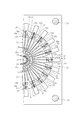
巻線対象は、図12に示すように、モータに使用されるロータ10であって、回転軸の周囲に放射状に突設された20本以上のティース11を有するものとする。そして、このロータ10には、線材16の巻き初め及び巻き終わりを収容する保持部13が形成されるものとする。
As shown in FIG. 12, the winding object is a
この巻線の対象となるロータ10は、保持部13を上側にしてロータ搬送手段40における支持台41に搭載され、その状態で搬送モータ43がアーム42を回転させ、それによりロータ10を支持台41に支持された状態で取付円板31の丸孔31aの下方にまで搬送する。
The
その後、ロータ昇降手段45における昇降ロッド46を上昇させ、昇降ロッド46の上端に支持台41を搭載し、更に昇降ロッド46を上昇させることにより、図7に示すように、ロータ10を丸孔31aに通過させて、複数のノズル22が包囲する位置にまで案内する。
Thereafter, the lifting
一方、ロータ支持手段50は、上昇したロータ10の上部を上方から押さえ部材53により押さえ、巻線対象であるロータ10の鉛直方向の位置を定め、かつその位置がずれることを防止する。それとともに、押さえ部材53は、複数のノズル22から操出される全ての線材16の巻き初め端部を咬持して、その巻初めの線材16a(図12)の位置を確定させる。
On the other hand, the rotor support means 50 presses the upper part of the raised
その後、押さえ部材53とともに巻線の対象であるロータ10を昇降させるとともに、ノズル駆動モータ36によりカム板34を回転させて、放射状に設けられた複数のノズル22が描く円を縮小又は拡大させて、その複数のノズル22から各ティース11間のスロット12にそれぞれ線材16を同時に繰出して、各ノズル22に対応する所定の2つのスロット12の間にそれぞれ同時に線材16を巻線する。
Thereafter, the
具体的には、先ず、放射状に設けられた複数のノズル22が描く円を縮小又は拡大させつつロータ10を上昇させて、複数のノズル22から線材16を同時に繰出して、図12に示すように、保持部13の周囲にその巻初めの線材16aを挿通させた後に、各ティース11間のスロット12にそれぞれ線材16を挿通させる。
Specifically, first, the
その後、ロータ10を軸中心に回転させてノズル22が対向するスロット12を変え、その状態で、放射状に設けられた複数のノズル22が描く円を縮小又は拡大させつつロータ10を下降させ、図13に示すように、複数のノズル22から別の各ティース11間のスロット12にそれぞれ線材16を同時に繰出して挿通させ、その後に保持部13の周囲にその巻終わりの線材16bを挿通させる。すると、スロット12から下方に突出した線材16は折り返されて別のスロット12に挿入されることに成り、この折り返された線材16が渡り線16cを形成することになる。
Thereafter, the
このように、複数のノズル22から同時に線材16を繰出して巻線し、渡り線16cを形成すると、図14に示すように、各渡り線16cが径方向内側へと押さえつけられ、互いに徐々に径方向内側に変位しながら絡み合った状態になる。よって、渡り線16cが膨らむようなことは防止され、巻線の占積率を向上させることができる。
In this way, when the
なお、巻初めの線材16a及び巻終わりの線材16bは保持部13に収容され、図7の符号38で示すかしめ部材によりその保持部13にかしめられて、この巻き初め及び巻終わりの線材16a,16bの離脱は防止されることになる。
The winding
巻初めの線材16a及び巻終わりの線材16bが保持部13にかしめられた後は、ロータ支持手段50における押さえ部材53による巻初めの線材16aの咬持を解消して、その押さえ部材53を上昇させてロータ10上部の押さえを解消し、昇降ロッド46を下降させてロータ10を支持台41とともに下降させ、その後、その支持台41が先端に搭載されたアーム42を回転させてそのロータ10を取り出して、一連の巻線作業を終了させる。このとき、他のアーム42の先端の支持台41に、次の巻線のためのロータ10を搭載させておけば、巻線が完了したロータ10の取り出しと、巻線を行うロータ10の装着を同時に行うことができる。
After the
そして、本発明の巻線方法にあっては、巻線工程と同時に蓄線工程を行うことを特徴とする。即ち、線材16を巻線している間に、巻線に必要な所定長さの線材16を複数のノズル22の数と同じ数まで集めて放射状に配置しておくのである。そして、線材16の巻線の後に、放射状に配置された前記複数のノズル22の個数と同じ数の所定長さの線材16を複数のノズル22にまで案内することにより、比較的迅速に巻線を行うことが可能になる。
The winding method of the present invention is characterized in that the storage step is performed simultaneously with the winding step. That is, while winding the
そして、本発明の巻線装置20及び巻線方法にあっては、単一のスプール17から繰出された線材16を所定の長さで操出して切断する線材操出切断手段61を備え、それにより得られた複数の線材16を線材運搬手段81により複数のノズル22にまで案内するので、ノズル22の数に等しい数のスプール17や伸張機62を必要としない。よって、ノズル22の数に等しい数のスプール17や伸張機62を必要としていた従来に比較して、装置は小型になり、広い設置場所を必要とすることはない。
The winding
ここで、巻線工程に係る時間が短く、その時間内において、単一の線材操出切断手段61により準備される所定長さの線材16の数がノズル22の数に達しない場合には、線材操出切断手段61を複数設け、蓄線手段71は複数の線材操出切断手段61により得られた所定長さの線材16をノズル22の数と同じ数まで集めて放射状に配置するようにすれば、巻線工程に係る時間内において、ノズル22の数に等しい数の所定長さの線材16を確実に準備することが可能となる。この場合であっても、線材操出切断手段61の数をノズル22の数未満とすることにより、装置は小型になり、広い設置場所を必要とすることはない。
Here, when the time relating to the winding process is short and the number of the
なお、このようなロータ10に巻線された被覆導線からなる線材16は、その後、図示しないバスバーに接続されることになるけれども、線材操出切断手段61によって線材16を操出す際に、バスバーに接続されることになる部位の被覆を被覆除去装置67により除去することにより、その後のバスバーへの接続作業を比較的容易に行うことが可能になる。
Note that the
ここで、上述した実施の形態では、2つの線材操出切断手段61により得られた所定長さの線材16をノズル22の数と同じ数まで集めて円板72上に放射状に配置して蓄線する場合を説明したけれども、線材操出切断手段61は2つでなくても良い。例えば、巻線工程に係る時間が比較的長く、その時間内において、単一の線材操出切断手段61により準備される所定長さの線材16の数がノズル22の数に達する場合には、線材操出切断手段61は1つであっても良い。また、巻線工程に係る時間がきわめて短い場合には、線材操出切断手段61は3つでも4つぐらい設け、それらにより得られた所定長さの線材16をノズル22の数と同じ数まで集めて放射状に配置するようにしても良い。
Here, in the above-described embodiment, the
12 ティース
13 スロット
16 線材
20 巻線装置
22 ノズル
61 線材操出切断手段
67 被覆除去装置
71 蓄線手段
81 線材運搬手段
12
Claims (5)
単一のスプール(17)から繰出された線材(16)を所定の長さで操出して切断する線材操出切断手段(61)と、
前記線材操出切断手段(61)により得られた所定長さの線材(16)を前記複数のノズル(22)の数と同じ数まで集めて放射状に配置する蓄線手段(71)と、
放射状に配置された複数の線材(16)を前記蓄線手段(71)から前記複数のノズル(22)にまで案内する線材運搬手段(81)と
を備えたことを特徴とする巻線装置。 The same number of nozzles (22) as the number of teeth (12) are provided radially, and the wire (16) is simultaneously fed from the plurality of nozzles (22) to the slots (13) between the teeth (12). In the winding device for winding the wire (16) simultaneously between two predetermined slots (13) corresponding to the nozzles (22),
Wire rod feeding and cutting means (61) for driving and cutting the wire rod (16) fed from a single spool (17) by a predetermined length;
The wire storage means (71) for collecting the wire rods (16) of a predetermined length obtained by the wire rod feeding and cutting means (61) up to the same number as the number of the plurality of nozzles (22) and arranging them radially.
A winding apparatus comprising: a wire rod conveying means (81) for guiding a plurality of radially arranged wire rods (16) from the wire storing means (71) to the plurality of nozzles (22).
前記線材(16)を巻線している間に単一のスプール(17)から繰出されて前記巻線に必要な所定長さに切断された線材(16)を複数の前記ノズル(22)の数と同じ数まで集めて放射状に配置する蓄線工程が行われ、
前記線材(16)の巻線の後に、放射状に配置された前記複数のノズル(22)の個数と同じ数の所定長さの線材(16)を前記複数のノズル(22)にまで案内する線材運搬工程が行われる
ことを特徴とする巻線方法。 A wire rod (16) is simultaneously fed from a plurality of nozzles (22) provided in the same number as the number of teeth (12) to the slots (13) between the teeth (12), respectively, to each nozzle (22). A winding method for winding the wire (16) between two corresponding predetermined slots (13) simultaneously,
While winding the wire rod (16), the wire rod (16) fed out from a single spool (17) and cut to a predetermined length necessary for the winding wire is formed by a plurality of nozzles (22). The accumulating process of collecting the same number as the number and arranging it radially is performed,
After the winding of the wire rod (16), the wire rod for guiding the wire rod (16) having a predetermined length equal to the number of the plurality of nozzles (22) arranged radially to the nozzles (22). A winding method characterized in that a carrying process is performed.
Priority Applications (6)
| Application Number | Priority Date | Filing Date | Title |
|---|---|---|---|
| JP2013156209A JP6173093B2 (en) | 2013-07-28 | 2013-07-28 | Winding device and winding method |
| EP14831554.2A EP3029816B1 (en) | 2013-07-28 | 2014-06-20 | Winding device and winding method |
| KR1020167000229A KR101719110B1 (en) | 2013-07-28 | 2014-06-20 | Winding device and winding method |
| US14/904,749 US10164506B2 (en) | 2013-07-28 | 2014-06-20 | Winding device and winding method |
| CN201480038745.5A CN105379081B (en) | 2013-07-28 | 2014-06-20 | Coiling apparatus and winding method |
| PCT/JP2014/066466 WO2015015948A1 (en) | 2013-07-28 | 2014-06-20 | Winding device and winding method |
Applications Claiming Priority (1)
| Application Number | Priority Date | Filing Date | Title |
|---|---|---|---|
| JP2013156209A JP6173093B2 (en) | 2013-07-28 | 2013-07-28 | Winding device and winding method |
Publications (3)
| Publication Number | Publication Date |
|---|---|
| JP2015027209A JP2015027209A (en) | 2015-02-05 |
| JP2015027209A5 JP2015027209A5 (en) | 2016-06-30 |
| JP6173093B2 true JP6173093B2 (en) | 2017-08-02 |
Family
ID=52431490
Family Applications (1)
| Application Number | Title | Priority Date | Filing Date |
|---|---|---|---|
| JP2013156209A Active JP6173093B2 (en) | 2013-07-28 | 2013-07-28 | Winding device and winding method |
Country Status (6)
| Country | Link |
|---|---|
| US (1) | US10164506B2 (en) |
| EP (1) | EP3029816B1 (en) |
| JP (1) | JP6173093B2 (en) |
| KR (1) | KR101719110B1 (en) |
| CN (1) | CN105379081B (en) |
| WO (1) | WO2015015948A1 (en) |
Families Citing this family (5)
| Publication number | Priority date | Publication date | Assignee | Title |
|---|---|---|---|---|
| CN105790528B (en) * | 2016-03-28 | 2017-12-05 | 河北工业大学 | Coil inserting apparatus |
| JP6785528B2 (en) * | 2016-10-14 | 2020-11-18 | Nittoku株式会社 | Winding device and winding method |
| KR102513514B1 (en) * | 2021-02-05 | 2023-03-23 | 동성이엔지 주식회사 | Multilayer Hairpin Aligner for Electric Vehicle Drive Motor |
| KR102513515B1 (en) * | 2021-02-05 | 2023-03-23 | 동성이엔지 주식회사 | Multi-layer hairpin expander for electric vehicle drive motor |
| KR102513516B1 (en) * | 2021-02-05 | 2023-03-23 | 동성이엔지 주식회사 | Multi-layer hairpin alignment jig for electric vehicle drive motor |
Family Cites Families (11)
| Publication number | Priority date | Publication date | Assignee | Title |
|---|---|---|---|---|
| JPS58195455A (en) * | 1982-05-10 | 1983-11-14 | Mitsuba Denki Seisakusho:Kk | Winding machine for armature |
| JPS5917851A (en) * | 1982-07-16 | 1984-01-30 | Shukichi Sakuma | Winding method of multipole core |
| SE508544C2 (en) * | 1997-02-03 | 1998-10-12 | Asea Brown Boveri | Method and apparatus for mounting a stator winding consisting of a cable. |
| JP3554672B2 (en) * | 1999-03-09 | 2004-08-18 | 株式会社ミツバ | Armature winding method |
| JP2003088064A (en) | 2001-09-07 | 2003-03-20 | Moric Co Ltd | Winding method of armature of electric rotating machine, and its equipment |
| DE10158267A1 (en) * | 2001-11-28 | 2003-06-18 | Bosch Gmbh Robert | Manufacturing multi-phase winding for electrical machine e.g. electric motor for motor vehicle, involves stripping conductor wire ends and electrically and mechanically joining them before pulling lengths into plate packet |
| JP4619057B2 (en) * | 2004-08-04 | 2011-01-26 | 株式会社ミツバ | Winding device for armature |
| JP4778389B2 (en) * | 2006-10-03 | 2011-09-21 | 日特エンジニアリング株式会社 | Coil winding method and apparatus |
| JP5563802B2 (en) * | 2009-10-20 | 2014-07-30 | 株式会社ミツバ | Winding method for brushless motor |
| JP2013258822A (en) * | 2012-06-12 | 2013-12-26 | Daikin Ind Ltd | Manufacturing method of stator and stator |
| JP5681249B1 (en) * | 2013-08-26 | 2015-03-04 | 本田技研工業株式会社 | Conductor piece supplying method and conductor piece supplying apparatus |
-
2013
- 2013-07-28 JP JP2013156209A patent/JP6173093B2/en active Active
-
2014
- 2014-06-20 WO PCT/JP2014/066466 patent/WO2015015948A1/en active Application Filing
- 2014-06-20 US US14/904,749 patent/US10164506B2/en active Active
- 2014-06-20 EP EP14831554.2A patent/EP3029816B1/en active Active
- 2014-06-20 KR KR1020167000229A patent/KR101719110B1/en active IP Right Grant
- 2014-06-20 CN CN201480038745.5A patent/CN105379081B/en active Active
Also Published As
| Publication number | Publication date |
|---|---|
| US20160172945A1 (en) | 2016-06-16 |
| CN105379081A (en) | 2016-03-02 |
| EP3029816A1 (en) | 2016-06-08 |
| US10164506B2 (en) | 2018-12-25 |
| KR101719110B1 (en) | 2017-03-22 |
| EP3029816A4 (en) | 2017-05-03 |
| KR20160017058A (en) | 2016-02-15 |
| WO2015015948A1 (en) | 2015-02-05 |
| JP2015027209A (en) | 2015-02-05 |
| CN105379081B (en) | 2018-07-10 |
| EP3029816B1 (en) | 2019-01-30 |
Similar Documents
| Publication | Publication Date | Title |
|---|---|---|
| JP6173093B2 (en) | Winding device and winding method | |
| US11165299B2 (en) | Coil assembling apparatus, coil assembling method and manufacturing apparatus of electrical rotating machine | |
| EP1962411B1 (en) | Winding device and winding method for a multipolar armature | |
| JP5400981B1 (en) | Wire twisting device, twisted wire manufacturing device, twisted wire manufacturing method | |
| JP2011130554A (en) | Device for manufacturing coil | |
| JP6211467B2 (en) | Winding device and winding method | |
| JP5680912B2 (en) | Toroidal coil manufacturing equipment | |
| KR102021662B1 (en) | motor coil winding apparatus to array multi coil and its method | |
| JP5389522B2 (en) | Coil forming method and coil forming apparatus | |
| JP5420463B2 (en) | Stator coil manufacturing apparatus and manufacturing method | |
| CN103779761B (en) | A kind of improved type folding bending apparatus of automatic stripping machine | |
| JP3986330B2 (en) | Winding method and winding device | |
| CN114977693A (en) | Unfolding type stator pulling and rolling type rounding device and application | |
| JP2010172108A (en) | Coil insertion method and coil turnover device | |
| US5709251A (en) | Method and device for winding coils for electric motors or generators | |
| JPH0795748A (en) | Wire winding device for inner-groove stator | |
| JP2007260731A (en) | Device and method for electrically caulking coil terminal | |
| JP2002028815A (en) | Cutting method and cutter for coil lead | |
| CN219259150U (en) | Electric welding wire winding machine | |
| JP5548802B2 (en) | Coil forming equipment | |
| JP5412393B2 (en) | Coil lead cutting method and cutting apparatus | |
| JP2006210741A (en) | Winding method and winding machine | |
| CN116779322B (en) | Automatic change paster inductance coiling machine | |
| CN216863222U (en) | Electrician's bobbin winder with uniform winding | |
| JP2017131100A (en) | Conductor bar stripping tool and method |
Legal Events
| Date | Code | Title | Description |
|---|---|---|---|
| A521 | Request for written amendment filed |
Free format text: JAPANESE INTERMEDIATE CODE: A523 Effective date: 20150914 |
|
| A521 | Request for written amendment filed |
Free format text: JAPANESE INTERMEDIATE CODE: A821 Effective date: 20150914 |
|
| A711 | Notification of change in applicant |
Free format text: JAPANESE INTERMEDIATE CODE: A711 Effective date: 20151013 |
|
| A521 | Request for written amendment filed |
Free format text: JAPANESE INTERMEDIATE CODE: A821 Effective date: 20151013 |
|
| A521 | Request for written amendment filed |
Free format text: JAPANESE INTERMEDIATE CODE: A523 Effective date: 20160516 |
|
| A621 | Written request for application examination |
Free format text: JAPANESE INTERMEDIATE CODE: A621 Effective date: 20160516 |
|
| TRDD | Decision of grant or rejection written | ||
| A01 | Written decision to grant a patent or to grant a registration (utility model) |
Free format text: JAPANESE INTERMEDIATE CODE: A01 Effective date: 20170621 |
|
| A61 | First payment of annual fees (during grant procedure) |
Free format text: JAPANESE INTERMEDIATE CODE: A61 Effective date: 20170704 |
|
| R150 | Certificate of patent or registration of utility model |
Ref document number: 6173093 Country of ref document: JP Free format text: JAPANESE INTERMEDIATE CODE: R150 |
|
| R250 | Receipt of annual fees |
Free format text: JAPANESE INTERMEDIATE CODE: R250 |
|
| R250 | Receipt of annual fees |
Free format text: JAPANESE INTERMEDIATE CODE: R250 |
|
| R250 | Receipt of annual fees |
Free format text: JAPANESE INTERMEDIATE CODE: R250 |
|
| R250 | Receipt of annual fees |
Free format text: JAPANESE INTERMEDIATE CODE: R250 |