CN1257596C - Winding method and device - Google Patents
Winding method and device Download PDFInfo
- Publication number
- CN1257596C CN1257596C CNB03120208XA CN03120208A CN1257596C CN 1257596 C CN1257596 C CN 1257596C CN B03120208X A CNB03120208X A CN B03120208XA CN 03120208 A CN03120208 A CN 03120208A CN 1257596 C CN1257596 C CN 1257596C
- Authority
- CN
- China
- Prior art keywords
- lead
- winding
- coil
- iron core
- tooth
- Prior art date
- Legal status (The legal status is an assumption and is not a legal conclusion. Google has not performed a legal analysis and makes no representation as to the accuracy of the status listed.)
- Expired - Fee Related
Links
- 238000004804 winding Methods 0.000 title claims abstract description 120
- 238000000034 method Methods 0.000 title claims description 57
- XEEYBQQBJWHFJM-UHFFFAOYSA-N Iron Chemical group [Fe] XEEYBQQBJWHFJM-UHFFFAOYSA-N 0.000 claims description 39
- 230000007246 mechanism Effects 0.000 claims description 22
- 238000003780 insertion Methods 0.000 claims description 9
- 230000037431 insertion Effects 0.000 claims description 9
- 230000008569 process Effects 0.000 description 12
- 238000005516 engineering process Methods 0.000 description 4
- 239000004020 conductor Substances 0.000 description 3
- 230000015572 biosynthetic process Effects 0.000 description 2
- 230000006872 improvement Effects 0.000 description 2
- RYGMFSIKBFXOCR-UHFFFAOYSA-N Copper Chemical compound [Cu] RYGMFSIKBFXOCR-UHFFFAOYSA-N 0.000 description 1
- 230000004888 barrier function Effects 0.000 description 1
- 230000008901 benefit Effects 0.000 description 1
- 229910052802 copper Inorganic materials 0.000 description 1
- 239000010949 copper Substances 0.000 description 1
- 230000007423 decrease Effects 0.000 description 1
- 238000004519 manufacturing process Methods 0.000 description 1
- 239000000463 material Substances 0.000 description 1
- 239000000203 mixture Substances 0.000 description 1
- 230000004048 modification Effects 0.000 description 1
- 238000012986 modification Methods 0.000 description 1
- 230000008450 motivation Effects 0.000 description 1
- NJPPVKZQTLUDBO-UHFFFAOYSA-N novaluron Chemical class C1=C(Cl)C(OC(F)(F)C(OC(F)(F)F)F)=CC=C1NC(=O)NC(=O)C1=C(F)C=CC=C1F NJPPVKZQTLUDBO-UHFFFAOYSA-N 0.000 description 1
- 230000001737 promoting effect Effects 0.000 description 1
- 241000894007 species Species 0.000 description 1
Images





Classifications
-
- H—ELECTRICITY
- H02—GENERATION; CONVERSION OR DISTRIBUTION OF ELECTRIC POWER
- H02K—DYNAMO-ELECTRIC MACHINES
- H02K3/00—Details of windings
- H02K3/46—Fastening of windings on the stator or rotor structure
-
- H—ELECTRICITY
- H02—GENERATION; CONVERSION OR DISTRIBUTION OF ELECTRIC POWER
- H02K—DYNAMO-ELECTRIC MACHINES
- H02K15/00—Processes or apparatus specially adapted for manufacturing, assembling, maintaining or repairing of dynamo-electric machines
- H02K15/08—Forming windings by laying conductors into or around core parts
- H02K15/085—Forming windings by laying conductors into or around core parts by laying conductors into slotted stators
-
- H—ELECTRICITY
- H02—GENERATION; CONVERSION OR DISTRIBUTION OF ELECTRIC POWER
- H02K—DYNAMO-ELECTRIC MACHINES
- H02K15/00—Processes or apparatus specially adapted for manufacturing, assembling, maintaining or repairing of dynamo-electric machines
- H02K15/06—Embedding prefabricated windings in the machines
-
- Y—GENERAL TAGGING OF NEW TECHNOLOGICAL DEVELOPMENTS; GENERAL TAGGING OF CROSS-SECTIONAL TECHNOLOGIES SPANNING OVER SEVERAL SECTIONS OF THE IPC; TECHNICAL SUBJECTS COVERED BY FORMER USPC CROSS-REFERENCE ART COLLECTIONS [XRACs] AND DIGESTS
- Y10—TECHNICAL SUBJECTS COVERED BY FORMER USPC
- Y10T—TECHNICAL SUBJECTS COVERED BY FORMER US CLASSIFICATION
- Y10T29/00—Metal working
- Y10T29/49—Method of mechanical manufacture
- Y10T29/49002—Electrical device making
- Y10T29/49009—Dynamoelectric machine
Landscapes
- Engineering & Computer Science (AREA)
- Power Engineering (AREA)
- Manufacturing & Machinery (AREA)
- Manufacture Of Motors, Generators (AREA)
Abstract
A winding device winds a wire (90) onto a core (8) having a plurality of teeth (8b) protruding from a yoke and having slots (8a) formed between each tooth (8b). The winding device winds the wire (90) by causing a nozzle (3) which lets out the wire (90) to perform a relative motion. The winding device is provided with pusher plates (72) which guide the wire (90) into the slots (8a), and inserts the wire (90) into the slots (8a) by causing the pusher plates (72) to move relative to the core (8).
Description
Invention field
The present invention relates to the improvement of method of winding and winding arrangement, this method and device are used for lead is wrapped in the stator core of motor or generator.
Background technology
The known traditional method of winding that is applicable to the inner-rotor type stator of people has direct method of winding and plug-in unit method of winding, and wherein, directly method of winding is that lead directly is wrapped on the tooth, and the plug-in unit method of winding is in the lead insertion groove that will wind in advance.Below (a) and (b) described in method be direct method of winding.
(a) a kind of direct method of winding, wherein, by inserting a shower nozzle, this shower nozzle is supplied to lead in each groove, thereby lead is wrapped on the iron core.
(b) a kind of direct method of winding, wherein, by moving a shower nozzle, this shower nozzle is supplied to lead on the outside of each groove, thereby lead is wrapped on the iron core.
Below method described in (c) be the plug-in unit method of winding.
(c) a kind of plug-in unit method of winding wherein, is wrapped in lead in advance along on the inboard rod like parts that is provided with of tooth, then with in this lead insertion groove.
The Tokkai2001-103716 of the Tokkai2000-270524 of Japan Patent office bulletin in 2000 and Japan Patent office calendar year 2001 bulletin discloses the winding arrangement that adopts direct method of winding, this winding arrangement comprises a hook, and this hook will be by in some lead-ingrooves on the lead of shower nozzle supply.
The Tokkai2000-245120 of Japan Patent office bulletin in 2000 discloses a kind of plug-in unit method of winding.
Summary of the invention
Although direct method of winding (a) and (b) be applicable to lead is wrapped in intensive winding on each tooth thick and fast that these methods are not suitable for the distributed winding that lead is wrapped in many teeth top.If attempt with (a) and the direct method of winding (b) carries out distributed winding, the initial lead that twines phase place in groove top will become a kind of barrier so, make the lead of the subsequent phase that will twine not to be wound.Even manually with in the lead insertion groove, also can be gapped between iron core and lead, thus can not improve the occupation efficiency (density) of lead with respect to iron core.
When the plug-in unit method of winding in using (c) carries out distributed winding, can be by improving the occupation efficiency of lead in the back with the lead insertion groove.But the length of winding coil end can increase, thereby causes the increase of coil dimension and need the step that forms end winding.In addition, along with the length increase of end winding, even this end winding does not influence the torque that prime mover produces, caloric value also can be owing to copper loss increases.
The purpose of this invention is to provide a kind of method of winding and winding arrangement, it can improve the occupation efficiency of coiler part, simultaneously end winding is shortened.
For realizing above purpose, the invention provides a kind of method of winding, be used on columned iron core, forming coil, described iron core comprises a columned yoke, from the radially outstanding many teeth of described yoke and be formed on groove between the adjacent described tooth, described method of winding comprises step: the shower nozzle that is provided for emitting lead; Be provided for the guiding element in the described lead lead-in groove; Move described shower nozzle with respect to described iron core three-dimensionally,, make two or more teeth be positioned at described first coil to form first coil; Upwards move described guiding element with respect to described iron core in the footpath of described iron core, described lead is inserted in the described groove by move described guiding element with respect to described iron core; Make the end winding of described first coil leave the axial end of described tooth; And when forming second coil, make at least one public tooth be included in described first coil and described second coil in, in the limit portion gap that end winding limited of insertion with described second coil, so that the limit portion of described second coil and the bottom connection of groove touch by described two or more teeth and described first coil.
According to the present invention, a kind of winding arrangement also is provided, be used on columned iron core, forming coil, described iron core comprises a columned yoke, from the radially outstanding many teeth of described yoke and be formed on groove between the adjacent described tooth, described winding arrangement comprises: shower nozzle is used to emit lead; Shower nozzle travel mechanism is used for moving described shower nozzle to form coil with respect to iron core three-dimensionally, and wherein the three-dimensional by described shower nozzle moves described lead is wrapped on two or more teeth; Guiding element is used in the described lead lead-in groove; Guiding element travel mechanism is used for upwards moving described guiding element with respect to iron core in the footpath of described iron core, wherein described lead is inserted in the described groove with respect to moving of described iron core by described guiding element; Wherein, described guiding element travel mechanism comprises a sliding part, and described sliding part can move diametrically along the axial end of described iron core, and described guiding element is removably attached on the described sliding part.
Details of the present invention and other feature and advantage will be illustrated in the other parts of this specification, and expression in the accompanying drawings.
Brief description of drawings
Fig. 1 is the cross section according to a kind of interior winding arrangement of first embodiment.
Fig. 2 is the fragmentary, perspective view of being somebody's turn to do interior winding arrangement according to first embodiment.
Fig. 3 A-3C is the end view according to the push pedal of first embodiment.
Fig. 4 is the fragmentary, perspective view in the winding process unshakable in one's determination, and a step in the method for winding is described.
Fig. 5 is the fragmentary, perspective view in the winding process unshakable in one's determination, and a step in the method for winding is described.
Fig. 6 is the fragmentary, perspective view in the winding process unshakable in one's determination, and a step in the method for winding is described.
Fig. 7 is the fragmentary, perspective view in the winding process unshakable in one's determination, and a step in the method for winding is described.
Fig. 8 is the fragmentary, perspective view in the winding process unshakable in one's determination, and a step in the method for winding is described.
Fig. 9 is the fragmentary, perspective view in the winding process unshakable in one's determination, and a step in the method for winding is described.
Figure 10 is the fragmentary, perspective view in the winding process unshakable in one's determination, and a step in the method for winding is described.
Figure 11 is the fragmentary, perspective view in the winding process unshakable in one's determination, and a step in the method for winding is described.
Figure 12 is the fragmentary, perspective view in the winding process unshakable in one's determination, and a step in the method for winding is described.
Figure 13 is the fragmentary, perspective view according to a kind of interior winding arrangement of second embodiment.
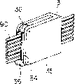
Figure 14 is the perspective view according to a kind of shower nozzle of second embodiment.
Figure 15 is the end view according to the shower nozzle of second embodiment.
The preferred embodiment of invention
Below will be based on the description of drawings embodiments of the invention.
In Fig. 1 to 12, be essentially cylindraceous unshakable in one's determination 8 stators that constituted inner-rotor type three-phase and quadrupole motor.This be essentially cylindraceous unshakable in one's determination 8 comprise one be essentially yoke cylindraceous and 24 from this yoke radially outstanding and isogonism, the tooth 8a (magnetic pole) that uniformly-spaced is provided with.Between adjacent tooth 8a, be formed with groove 8b.For forming stator coil, finish that lead 90 is wrapped in five distributed winding on the tooth 8a.
Along the circumferential direction be formed with four groups of coils, every group all comprises each in U, V and the W phase coil.Each coil is all by the coil side portion 92 in the groove 8b that packs into, from this groove 8b, exposes and the end winding 91 of five tooth 8a tops of extend through, and 103 3 part compositions of the bent angle portion between this coil side portion 92 and end winding 91.Radially form each end winding 91 according to priority, wherein, U phase coil end 91u is positioned at outermost, and V phase coil end 91v is positioned at the centre position, and W phase coil end 91w is positioned at the most inboard.This U, V and W coil comprise at least one public tooth.Since this U, V and W phase coil end 91u, 91v, and 91w hinders mutually, so they are overlapping hardly.
What it should be noted that is that the present invention is not limited to the aforementioned electric motivation, can be used for the motor that other has the different numbers of phases and number of poles.For example, two-phase four-pole motor, its stator comprise 16 teeth and groove, lead are wrapped on two teeth simultaneously.
Fig. 1 has represented a kind of interior winding arrangement 1 that is used for automatically making stator coil.Should comprise the stator support 11 that is used to support iron core 8 by interior winding arrangement 1, and the calibration motor 13 that is used to rotate this stator support 11.Via bearing this stator support 11 is supported on the framework 12 rotationally.Via gear 93 and ring gear 94 rotation of calibration motor 13 is passed to stator support 11.Here, the axis of centres of stator support 11 is set at the Z axle, this Z axle has formed unshakable in one's determination 8 the axis of centres.
Should comprise the shower nozzle 3 that is used to emit lead 90 by interior winding arrangement 1, and be used for respect to the 8 shower nozzle travel mechanisms 10 that move this shower nozzle 3 unshakable in one's determination three-dimensionally.This shower nozzle travel mechanism 10 comprises the head 4 that is used to support each shower nozzle 3, be used to support the cylindric head support bar 5 of this head 4, be used for rotating the head support bar rotating mechanism 20 of this head support bar 5, and make this head support bar 5 along the reciprocating head support bar travel mechanism 30 of Z-direction around the Z axle.
This head support bar rotating mechanism 20 comprises the spline 21 that inserts in head support bar 5 neighborings, gear 22 with these spline 21 slip joint, with these gear 22 pinion in mesh 23, and be used to order about the head support bar rotation motor 24 that this pinion 23 rotates.The rotation of this head support bar rotation motor 24 is delivered to head support bar 5, and rotation head 4 thus.This head support bar rotation motor 24 is fixed on the framework 12, gear 22 is supported on the framework 12 so that this gear 22 is meshed with pinion 23 simultaneously via bearing 25.As a result, can greatly reduce the rotatable material that includes head 4.
This head support bar travel mechanism 30 comprises via bearing 33 and comes supporting head part support bar 5 so that the movable base 7 that this head support bar 5 can rotate around the Z axle, support this movable base 7 so that the guide rail 9 that this pedestal 7 can move with respect to framework 12 on Z-direction, be screwed into the ball screw 31 in this movable base 7, and be used to order about the movable base CD-ROM drive motor 32 that this ball screw 31 rotates.When coming rotation ball screw rod 31 by this movable base CD-ROM drive motor 32, movable base 7 just moves up and down, and just makes this head 4 do the motion similar with movable base 7 on Z-direction via head support bar 5 thus.
Shower nozzle travel mechanism 10 also has and is used to make shower nozzle 3 to move radially mechanism 40 to the shower nozzle that the radial direction basically with respect to the Z axle moves, and thus, lead 90 is aimed at tooth 8a.As shown in Figure 2, this shower nozzle moves radially mechanism 40 and comprises and can make shower nozzle 3 to the tooth bar 42 that slides and move with respect to the radial direction basically of Z axle, with these tooth bar 42 pinion in mesh 43, pass head support bar 5 supporting the cylindric shower nozzle carriage release lever 6 of this pinion 43, and be used to order about the shower nozzle carriage release lever rotating mechanism 50 that this shower nozzle carriage release lever 6 rotates.
When this shower nozzle carriage release lever 6 rotated with respect to head support bar 5, pinion 43 just rotated with respect to tooth bar 42, and each shower nozzle 3 just moves to the radial direction basically with respect to the Z axle like this.As a result, just not necessarily the shower nozzle carriage release lever rotation motor 54 that this gear 43 is rotated to be supported on the head 4, thereby can greatly reduce the mobile specie that includes this head 4.
This nozzle radial direction travel mechanism 40 is not limited to adopt the structure of pinion 43, but can adopt chain structure, cam configuration or analog so that shower nozzle carriage release lever 6 and each shower nozzle 3 interlocking.
In addition, shower nozzle 3 quantity on the single head 4 are not limited to one, can for example will side by side carry out winding on a plurality of positions according to specification requirement and increase to two or three.
From unshowned lead source of supply, lead 90 is guided to shower nozzle 3 via tensioning apparatus, the inside of passing shower nozzle carriage release lever 6.This lead 90 of being supplied can be many an of bundle.Just doing like this to increase occupation efficiency, thereby improves motor performance.
Shower nozzle carriage release lever rotating mechanism 50 comprises the spline 51 that inserts in shower nozzle carriage release lever 6 neighborings, gear 52 with these spline 51 slip joint, with these gear 52 pinion in mesh 53, and be used to order about the shower nozzle carriage release lever rotation motor 54 that this pinion 53 rotates.The rotation of this shower nozzle carriage release lever rotation motor 54 is delivered to shower nozzle carriage release lever 6, and rotation pinion 43 thus.This shower nozzle carriage release lever rotation motor 54 is fixed on the framework 12, gear 52 is supported on the framework 12 so that this gear 52 is meshed with pinion 53 simultaneously via bearing 55.
Interior winding arrangement 1 has the controller 100 that is used to control each servo motor 24,32,54 operation.This controller 100 is a kind of controller based on microprocessor, comprises microprocessor and is used for stored program memory.
This controller 100 is to construct like this, when rotation head 4, head support bar rotation motor 24 is rotated mutually synergistically with shower nozzle carriage release lever rotation motor 54, thereby head support bar 5 is rotated to identical direction with identical rotating speed (revolutions per) with shower nozzle carriage release lever 6.When radially direction moves shower nozzle 3 basically, stop the rotating operation of head support bar rotation motor 24, shower nozzle carriage release lever rotation motor 54 is rotated, shower nozzle carriage release lever 6 is just with respect to 5 rotations of head support bar like this.
Shower nozzle travel mechanism 10 is such structures, motor 24,32, and 54 are not connected on the head 4, can reduce the size of this head 4 thus and accelerate the translational speed of this head 4.As a result, can shorten the time that this winding is operated required consumption, head 4 also can be used for smaller iron core 8 simultaneously.In addition because each motor 24,32,54 all is fixed on the framework 12, be used for just can being arranged to the electric wire that these motors transmit electric currents changeless, thereby eliminate misgivings to relevant electric wire disconnection.
Interior winding arrangement 1 comprises guiding element 71, is used to guide the lead 90 that will be wrapped in the groove 8b, and guiding element travel mechanism 60, is used for moving this guiding element 71 with respect to unshakable in one's determination 8 in its radial direction.Relatively mobile shower nozzle 3, thus with lead 90 hooks on guiding element 71, and relatively move this guiding element 71, thus with institute's hook around lead 90 insertion groove 8b in.
This guiding element 71 comprises two pairs of up and down push pedals 72 and a pair ofly promote 73 up and down.For per five tooth 8a, twine lead 90 around these five tooth 8a, be arranged to from the axial end of end tooth 8a push pedal 72 outstanding up and down, twine lead 90 (forming coil) around this end tooth, will promote 73 simultaneously and be arranged to give prominence to up and down from the axial end of center tooth 8a around this end tooth.End tooth is the tooth that contacts and be positioned at the annular end place of the coil that forms with coil side portion 92.Center tooth be located substantially on the tooth at place in the middle of the coil that forms.
Around stator support 11 three pairs of guiding element travel mechanisms 60 up and down are set.Each guiding element travel mechanism 60 all comprises the guide rail 65 that is connected with framework 12, by the sliding part 66 of these guide rail 65 sliding supports, and the ball screw 67 that is meshed with this sliding part 66, and order about the guiding element CD-ROM drive motor 68 that this ball screw 67 rotates.This guiding element CD-ROM drive motor 68 is fixed on the framework 12, and when these guiding element CD-ROM drive motor 68 rotation ball screw rods 67, sliding part 66 is just done parallel motion with respect to the radial direction of Z axle.Each guiding element CD-ROM drive motor 68 of controller 100 may command.
This sliding part 66 is designed to pass stator support 11 and slides along the axial end of tooth 8a.
The method of winding of winding arrangement 1 in this then, is described with reference to Fig. 4 to 12.Fig. 4 to 12 has illustrated the process of making the W phase coil, but the process of manufacturing U phase and V phase coil also is similar to the process of making the W phase coil.
After the user was installed in iron core 8 on the stator support 11, winding arrangement 1 was just carried out following steps with winding around continuously in this.Controller 100 is being stored and the following steps corresponding programs, and sends command signal according to this program.Motor 13,24,32,54,68 can operate according to the command signal that controller 100 sends.
In step S1, the lead clamping device is caught the top of the lead 90 of emitting from shower nozzle 3.
In step S2, guiding element CD-ROM drive motor 68 is rotated, and sliding part 66 just passes stator support 11 and end winding 91 like this.The end of sliding part 66 arrives the position near tooth 8a tip.Then, the user is just with push pedal 72 with promote 73 attached on this sliding part 66.
In step S3, movable base CD-ROM drive motor 32 is rotated so that head 4 descends and enters unshakable in one's determination 8 inside, so just shower nozzle 3 is moved near the precalculated position the tooth 8a.The tip surface of tooth is to the head 4 that is positioned at unshakable in one's determination 8.
In step S4, shower nozzle 3 carries out a kind of relative motion, thus with lead 90 hooks on guiding element 71, and guiding element 71 also carries out a kind of relative motion, thereby will be hook around lead 90 insertion groove 8b in, therefore, the lead 90 that comes out from shower nozzle 3 is by once on 5 tooth 8a.
Here, interior winding arrangement 1 is finished the operation of this formation coil by following steps.
In step S4a, rotation head 4, shower nozzle 3 beginnings are simultaneously moved to circumferencial direction along the upper surface of tooth 8a.Here, head support bar rotation motor 24 rotates to a direction mutually synergistically with jet pipe carriage release lever rotation motor 54, thereby head support bar 5 is rotated to equidirectional with identical rotating speed with jet pipe carriage release lever 6.As a result, lead 90 just is hooked in a push pedal 72 and promotes on 73.At this moment, this push pedal 72 and distribution 73 are positioned at the positions (Fig. 4) near the crown end.
In step S4b, rotate guiding element CD-ROM drive motor 68, thus, be used to guide one of them upside push pedal 72 of this lead 90 radially outwards to move, shown in arrow among Fig. 5.
In step S4c, after lead 90 had been hooked in another upside push pedal 72, head support bar rotation motor 24 and jet pipe carriage release lever rotation motor 54 stopped operating, and shower nozzle 3 just no longer moves (see figure 6) along the upper surface of tooth 8a to circumferencial direction like this.
In step S4d, movable base CD-ROM drive motor 32 begins to rotate to fall shower nozzle 3, rotates this guiding element CD-ROM drive motor 68 simultaneously, push pedal 72 and last distribution 73 is radially outwards moved, shown in arrow among Fig. 7.At this moment, utilize a pattern 81 these leads 90 of guiding, make this lead 90 enter (see figure 7) in the groove 8b.This pattern 81 is arranged to towards the tip of a tooth, and this tooth is positioned near the groove that this lead will be introduced into.Because this pattern 81 will be inducted in the groove 8b from the lead 90 that shower nozzle 3 is emitted, thereby just can twine this lead 90 reposefully.
In step S4e, through one after the following push pedal 72, movable base CD-ROM drive motor 32 stops operating at this lead 90, thereby makes shower nozzle 3 no longer along the side decline (see figure 8) of tooth 8a.
In step S4f, for rotating this shower nozzle 3 to circumferencial direction in the lower surface along tooth 8a, 54 beginnings of head support bar rotation motor 24 and jet pipe carriage release lever rotation motor are rotated mutually synergistically, just make thus head support bar 5 and jet pipe carriage release lever 6 with step S4a in identical rotating speed to step S4a in opposite direction rotation.As a result, lead 90 just is hooked in one of them following push pedal 72.Equally, rotate guiding element CD-ROM drive motor 68, the push pedal 72 of this lead 90 of guiding is radially outwards moved, shown in arrow among Fig. 9.
In step S4g, after lead 90 had been hooked in another downside push pedal 72, head support bar rotation motor 24 and jet pipe carriage release lever rotation motor 54 stopped operating, and shower nozzle 3 just no longer moves (see figure 10) along the lower surface of tooth 8a to circumferencial direction like this.
In step S4h, movable base CD-ROM drive motor 32 begins to rotate to promote shower nozzle 3, rotates this guiding element CD-ROM drive motor 68 simultaneously, push pedal 72 and following distribution 73 is radially outwards moved, shown in arrow among Figure 11.
In step S4i, this lead 90 through one on after the push pedal 72, movable base CD-ROM drive motor 32 stops operating, thereby shower nozzle 3 is no longer risen on the side of tooth 8a.At this moment, radially outer moving all finished in all push pedals 72.
In step S4j, rotate this guiding element CD-ROM drive motor 68, with radially inwardly, move all push pedals 72 and promote 73 (Figure 12) up and down up and down towards the tip of tooth.
By the operation of repeating step S4a to S4j, can in a row twine this lead 90, the coil that has preset width and predetermined number of layers with formation.
In step S5, after the user has removed the push pedal 72 on the sliding part 66 and promoted 73, rotate this guiding element CD-ROM drive motor 68, thereby in stator support 11, pull out this sliding part 66.
In case finish this step, calibration motor 13 just makes unshakable in one's determination 8 to rotate a predetermined angle, thereby should turn to next winding position by iron core 8.Then, once more sliding part 66 is inserted in the stator support 11, fixedly push pedal 72 and distribution 73, and repeat similar step.
When the winding of all tooth 8a was all finished, movable base CD-ROM drive motor 32 promoted head 4, with these head 4 emersions unshakable in one's determination 8.Because a bit being kept by unshowned lead clamping device on the lead 90, is just with the lead 90 between unshowned cutter sweep cut-out tooth 8a and the lead clamping device.So the user just can move apart stator support 11 with unshakable in one's determination 8.
Speak of as above, at first the sliding part 66 of class plate shape is inserted unshakable in one's determination 8 with U phase coil end 91u between and between iron core 8 and the V phase coil end 91v, so just can move guiding element 71 along the axial end of this iron core 8.Before twining the W phase coil, twine U phase and V phase coil.Thus, W phase coil end 91w just is formed near the axial end of iron core 8, thereby can shorten the length of end winding 91.
When four push pedals 72 promote each end winding 91, just coil side portion 92 is pushed to the bottom of groove, and make this end winding 91 be positioned at preposition.In this case, just the bent angle portion 103 of W phase coil and coil side portion 92 are inserted in the space that the V phase coil end 91v by tooth and winding in advance limited.
Promote 73 when promoting each end winding 91 central when two, just the end winding 91 of every phase is lined up row, and compress the end winding 91 of every phase.
When twining the U phase winding, the end face 74 of push pedal 72 promotes lead 90, and promote 73 simultaneously and also promote lead 90, the result, U phase coil end 91 just is formed on the radial outside position of groove 8b and tooth 8a.Radially outward pushing away coil side portion 92 that this lead 90 can make the U phase coil on unshakable in one's determination 8 axial end touches with the bottom connection of groove 8b basically.
So, when twining the V phase winding, push pedal 72 can be moved near the rear portion of groove 8b, thereby the gap between minimizing coil side portion 92 and the groove 8b bottom increases occupation efficiency.Radially outward pushing away coil side portion 92 that this lead 90 can make the V phase coil on unshakable in one's determination 8 axial end touches with the bottom connection of groove 8b basically.
When twining the V phase winding, lead 90 is placed on the step-portion 76 of push pedal 72, and utilize the end face 75 of push pedal 72 to promote this lead 90.Also can utilize distribution 73 to promote this lead 90.Thus, just radially lift V phase coil end 91 from the axial end of tooth 8a.
So, when twining the W phase winding, push pedal 72 can be moved near the rear portion of groove 8b, thereby the gap between minimizing coil side portion 92 and the groove 8b bottom increases occupation efficiency.Radially outward pushing away coil side portion 92 that this lead 90 can make the W phase coil on unshakable in one's determination 8 axial end touches with the bottom connection of groove 8b basically.
By when twining lead 90, utilize push pedal 72 that this lead 90 is pushed in the groove 8b by this way, the gap between coil side portion 92 and the groove 8b bottom can be reduced, occupation efficiency can be increased thereby compare with traditional direct method of winding that lead directly is wrapped on the tooth.
U phase coil end 91u is positioned at the outermost radially along groove 8b, and V phase coil end 91v lifts from the axial end of tooth 8a simultaneously.The end 91w of a part of W phase coil is inserted between V phase coil end 91v and the tooth 8a.Therefore, compare with traditional plug-in unit method of winding, this method can shorten the length in order to the lead 90 that constitutes end winding 91, thereby can reduce coil dimension.Also can reduce coil resistance, to improve engine performance.
W phase coil end 91w is shorter than U phase coil end 91u and V phase coil end 91v.But it should be noted that employed leads 90 amounts of groove 8b interior loop limit portion 92 equate, therefore, all equate by making every electric current in mutually, just can every mutually in the identical torque of generation.
In addition, compare with traditional plug-in unit method of winding, this method can reduce widely behind winding and to form end winding needed man-hour, thereby boosts productivity.
In addition, compare with traditional plug-in unit method of winding, this method also can reduce the size of winding arrangement, reduces the cost of winding arrangement.
Second embodiment shown in Figure 13 to 15 will be described now.It should be noted that, distributed identical reference number with the identical assembly of first embodiment.Except that shower nozzle 3 and pattern 81, first embodiment is identical with second embodiment.
This shower nozzle 3 has two control boards 34, and this control board 34 is used to emit the lead 90 of vertical alignment.This control board 34 is inserted in the groove 8b, thus lead 90 is wrapped on the tooth 8a.
With the top and the bottom of pair of rolls 36 attached to this main body 35.Against lead 90 these two rollers 36 of rotation of upper and lower side, just can in shower nozzle 3, emit lead 90 reposefully by respectively.
In addition, this two roller 36 is arranged to be positioned near the upper and lower end parts of control board 34 and guides this lead 90, so just can emit lead 90 reposefully.
As shown in figure 13, by will in the control board 34 insertion groove 8b lead 90 being wrapped on the tooth 8a, be used for like this pattern in the lead 90 lead- ingroove 8b 81 has just no longer been needed.In this case, even the inlet of groove 8b is very narrow, also can easily lead 90 be inserted.Many leads 90 form a branch of, and are wrapped in reposefully in tooth 8a and the push pedal 72.As a result, can prevent that this lead 90 from owing to friction is twisted together, can increase occupation efficiency simultaneously, improve engine performance.
The full content that is incorporated herein Japanese patent application P2002-61666 (application on March 7th, 2002) for your guidance.
Although invention has been described for above reference specific embodiment of the present invention, the present invention is not limited to above-described embodiment.Those skilled in the art can make improvements and modification the above embodiment under the enlightenment of above content.Limit scope of the present invention with reference to following claims.
Claims (9)
1. a method of winding is used for forming coil on columned iron core, and described iron core comprises a columned yoke, from the radially outstanding many teeth of described yoke and be formed on groove between the adjacent described tooth, and described method of winding comprises step:
Be provided for emitting the shower nozzle of lead;
Be provided for the guiding element in the described lead lead-in groove;
Move described shower nozzle with respect to described iron core three-dimensionally,, make two or more teeth be positioned at described first coil to form first coil;
Upwards move described guiding element with respect to described iron core in the footpath of described iron core, described lead is inserted in the described groove by move described guiding element with respect to described iron core;
Make the end winding of described first coil leave the axial end of described tooth; And
When forming second coil, make at least one public tooth be included in described first coil and described second coil in, in the limit portion gap that end winding limited of insertion with described second coil, so that the limit portion of described second coil and the bottom connection of groove touch by described two or more teeth and described first coil.
2. method of winding as claimed in claim 1 also comprises step:
One sliding part is provided, and this sliding part can move along axial end unshakable in one's determination diametrically; And
Described guiding element is attached on this sliding part.
3. a winding arrangement is used for forming coil on columned iron core, and described iron core comprises a columned yoke, from the radially outstanding many teeth of described yoke and be formed on groove between the adjacent described tooth, and described winding arrangement comprises:
Shower nozzle is used to emit lead;
Shower nozzle travel mechanism is used for moving described shower nozzle to form coil with respect to iron core three-dimensionally, and wherein the three-dimensional by described shower nozzle moves described lead is wrapped on two or more teeth;
Guiding element is used in the described lead lead-in groove;
Guiding element travel mechanism is used for upwards moving described guiding element with respect to iron core in the footpath of described iron core, wherein described lead is inserted in the described groove with respect to moving of described iron core by described guiding element;
Wherein, described guiding element travel mechanism comprises a sliding part, and described sliding part can move diametrically along the axial end of described iron core, and described guiding element is removably attached on the described sliding part.
4. winding arrangement as claimed in claim 3 is characterized in that: described guiding element comprises a push pedal, and this push pedal has an end face that extends on the axle of iron core, and this push pedal is used to promote lead.
5. winding arrangement as claimed in claim 3 is characterized in that: described sliding part is to be provided with like this, thereby makes between the end winding of its axial end that passes described iron core and the described axial end unshakable in one's determination of covering.
6. winding arrangement as claimed in claim 3 is characterized in that: described guiding element comprises two pairs of push pedals that are used for described coil, wherein constitute a pair of push pedal and face mutually in the axial direction,
Each push pedal all is set on the axial end of tooth at the circumferential ends place that is positioned at the coil that will form.
7. winding arrangement as claimed in claim 3 is characterized in that: described guiding element comprises a pair of opposed facing in the axial direction distribution,
Each is promoted on the axial end of the tooth that all is set at the centre that is positioned at the coil that will form.
8. winding arrangement as claimed in claim 3 is characterized in that: also comprise a pattern, be used for described lead is introduced in the described groove that described pattern is arranged to the tip in the face of a tooth, this tooth be positioned at groove that described lead is introduced near.
9. winding arrangement as claimed in claim 3 is characterized in that: described shower nozzle comprises a control board, and described control board is used to emit many leads of vertical alignment,
Described control board inserts in the described groove, thus described many leads is wrapped on described two or more tooth.
Applications Claiming Priority (2)
| Application Number | Priority Date | Filing Date | Title |
|---|---|---|---|
| JP061666/2002 | 2002-03-07 | ||
| JP2002061666A JP3669966B2 (en) | 2002-03-07 | 2002-03-07 | Winding method and winding device |
Publications (2)
| Publication Number | Publication Date |
|---|---|
| CN1444328A CN1444328A (en) | 2003-09-24 |
| CN1257596C true CN1257596C (en) | 2006-05-24 |
Family
ID=27751196
Family Applications (1)
| Application Number | Title | Priority Date | Filing Date |
|---|---|---|---|
| CNB03120208XA Expired - Fee Related CN1257596C (en) | 2002-03-07 | 2003-03-07 | Winding method and device |
Country Status (5)
| Country | Link |
|---|---|
| US (1) | US6749144B2 (en) |
| EP (1) | EP1343244A3 (en) |
| JP (1) | JP3669966B2 (en) |
| KR (1) | KR100522058B1 (en) |
| CN (1) | CN1257596C (en) |
Cited By (1)
| Publication number | Priority date | Publication date | Assignee | Title |
|---|---|---|---|---|
| CN101621232B (en) * | 2008-07-02 | 2011-09-14 | 日特机械工程株式会社 | Coiling method and device for bonding coil |
Families Citing this family (41)
| Publication number | Priority date | Publication date | Assignee | Title |
|---|---|---|---|---|
| US20090077020A9 (en) * | 1998-12-04 | 2009-03-19 | Toong Hoo-Min | Systems and methods of searching databases |
| JP2003047215A (en) * | 2001-08-03 | 2003-02-14 | Moric Co Ltd | Method and apparatus for winding coil of armature of rotating field type electric appliance |
| US20060224975A1 (en) * | 2005-04-01 | 2006-10-05 | Paul Albrecht | System for creating a graphical application interface with a browser |
| ITTO20020766A1 (en) * | 2002-09-04 | 2004-03-05 | Giovanni Fortuna | METHOD FOR BINDING MACHINE WINDINGS |
| CN1327598C (en) * | 2002-10-04 | 2007-07-18 | 松下电器产业株式会社 | Method of winding stator in motor |
| US7017850B2 (en) * | 2002-11-14 | 2006-03-28 | Atop S.P.A. | Wire manipulator methods and apparatus for dynamo-electric machine coil winding |
| DK1473817T3 (en) * | 2003-02-13 | 2009-08-03 | Atop Spa | Apparatus and method for winding wire on a core of a dynamoelectric machine |
| US20050093383A1 (en) * | 2003-11-03 | 2005-05-05 | Wen-Shing Wu | Fan motor |
| JP3913242B2 (en) | 2004-09-13 | 2007-05-09 | 日特エンジニアリング株式会社 | Multipole armature winding method and winding apparatus |
| JP4665595B2 (en) * | 2005-04-28 | 2011-04-06 | トヨタ自動車株式会社 | Winding structure of rotating electrical machine |
| EP1722464B1 (en) * | 2005-05-11 | 2019-05-08 | Brose Fahrzeugteile GmbH & Co. KG, Würzburg | Method for winding a stator of an electric motor and stator for an electric motor |
| DE102005049536A1 (en) * | 2005-10-17 | 2007-04-19 | Robert Bosch Gmbh | Method and device for winding stator or armature teeth |
| ITPI20060031A1 (en) * | 2006-03-13 | 2007-09-14 | Atop Spa | EQUIPMENT AND METHODS FOR WRAPPING WIRE COILS AROUND NUCLEI OF ELECTRIC MACHINES. |
| US20080016676A1 (en) * | 2006-07-18 | 2008-01-24 | Jones Robert M | Automatic winder for an inside brushless stator |
| JP4600385B2 (en) | 2006-11-21 | 2010-12-15 | トヨタ自動車株式会社 | Winding device |
| JP5075429B2 (en) * | 2007-02-26 | 2012-11-21 | 日特エンジニアリング株式会社 | Multi-pole armature winding apparatus and winding method |
| US8253524B2 (en) * | 2007-10-04 | 2012-08-28 | Keihin Corporation | Coil winding system and method for fabricating molded coil |
| US20090261194A1 (en) * | 2008-04-16 | 2009-10-22 | Nittoku Engineering Co., Ltd. | Winding apparatus and winding method |
| JP5204627B2 (en) * | 2008-11-12 | 2013-06-05 | 日特エンジニアリング株式会社 | Connecting coil winding method and connecting coil winding apparatus |
| WO2011031711A2 (en) * | 2009-09-08 | 2011-03-17 | Windamatic Systems, Inc. | Movable needle winding head for a winding machine |
| SI2309626T1 (en) * | 2009-10-12 | 2013-01-31 | Aumann Gmbh | Coiling method, in particular to form electrical coils |
| US20110260572A1 (en) | 2010-04-27 | 2011-10-27 | Honda Motor Co., Ltd. | Motor stator and manufacturing method of motor stator |
| TWI413344B (en) * | 2010-05-05 | 2013-10-21 | Taigene Electric Machinery Co Ltd | Stator core winding method for motor and structure thereof |
| JP5508147B2 (en) * | 2010-06-02 | 2014-05-28 | 日特エンジニアリング株式会社 | Winding machine and winding method |
| US8333340B2 (en) * | 2011-01-17 | 2012-12-18 | General Electric Company | System and method for reinforcing a substrate |
| CN102497068B (en) * | 2011-11-30 | 2014-07-09 | 南车株洲电机有限公司 | Direct-driven wind driven generator multi-turn molding winding turn groove technology and auxiliary apparatus thereof |
| JP5761690B2 (en) * | 2011-12-15 | 2015-08-12 | アイシン・エィ・ダブリュ株式会社 | Stator manufacturing method and coil insertion device |
| JP5841017B2 (en) * | 2012-07-12 | 2016-01-06 | 本田技研工業株式会社 | Electrical conductor insertion device |
| JP6112714B2 (en) * | 2013-04-12 | 2017-04-12 | 日特エンジニアリング株式会社 | Coil manufacturing equipment |
| JP2015012631A (en) * | 2013-06-26 | 2015-01-19 | 株式会社小松製作所 | Winding method and winding device |
| WO2015041221A1 (en) * | 2013-09-18 | 2015-03-26 | 本田技研工業株式会社 | Alignment method and alignment device |
| CN103701276A (en) * | 2013-12-31 | 2014-04-02 | 泰信电机(苏州)有限公司 | Resistance adjustment device applied to line feeding device |
| DE102014009799A1 (en) * | 2014-07-03 | 2016-01-07 | Audi Ag | Method and device for producing an electric machine |
| US10404145B2 (en) * | 2016-03-18 | 2019-09-03 | WGE Equipment Solutions LLC | Stator winding gun head |
| CN106712410B (en) * | 2016-12-28 | 2023-03-24 | 重庆市爱华机电有限公司双福分公司 | Armature winding flat copper wire end torsion device |
| CN106712399B (en) * | 2016-12-28 | 2023-02-28 | 重庆市爱华机电有限公司双福分公司 | Armature winding flat copper wire head twisting device |
| CN106847496B (en) * | 2016-12-29 | 2019-05-21 | 宜春高登兰电子科技有限公司 | Magnetic core coiling auxiliary device |
| JP7480729B2 (en) * | 2021-03-16 | 2024-05-10 | トヨタ自動車株式会社 | Coil assembly method and coil assembly device |
| KR102664478B1 (en) * | 2021-10-19 | 2024-05-14 | 주식회사 야호텍 | Apparatus of winding coil with wire tension holding |
| CN115118107B (en) * | 2022-08-05 | 2023-10-20 | 中达电机股份有限公司 | Adjustable large winding die tooling for hard winding of high-voltage motor and winding process |
| CN116345740B (en) * | 2023-03-30 | 2024-02-06 | 海宁艾弗洛电器有限公司 | Rotor core winding mechanism of motor and use method using same |
Family Cites Families (19)
| Publication number | Priority date | Publication date | Assignee | Title |
|---|---|---|---|---|
| US2847170A (en) * | 1957-03-18 | 1958-08-12 | Fort Wayne Tool Die & Engineer | Winding apparatus for distributed wound stators |
| FR1173379A (en) * | 1957-03-27 | 1959-02-24 | Forges Ateliers Const Electr | Winding machine |
| GB842287A (en) * | 1957-04-05 | 1960-07-27 | Westinghouse Electric Corp | Improvements in or relating to coil winding machines |
| US2949789A (en) * | 1958-02-27 | 1960-08-23 | Fort Wayne Tool Die & Engineer | High speed stator winding apparatus |
| DE1262422B (en) * | 1958-09-18 | 1968-03-07 | Micafil Ag | Stator winding machine |
| US3334825A (en) * | 1964-01-27 | 1967-08-08 | Lincoln Tool And Mfg Co | Stator coil winding machine |
| US3381907A (en) * | 1966-04-14 | 1968-05-07 | Possis Machine Corp | Coil leg retainer |
| US3995785A (en) * | 1973-02-12 | 1976-12-07 | Essex International, Inc. | Apparatus and method for forming dynamoelectric machine field windings by pushing |
| US4053111A (en) * | 1976-12-06 | 1977-10-11 | Windamatic Systems, Inc. | Apparatus and method for producing distributed stator windings |
| US5394046A (en) * | 1992-09-21 | 1995-02-28 | Globe Products Inc. | Stator and stator winding method and apparatus |
| US5860615A (en) * | 1995-10-30 | 1999-01-19 | Labinal Components And Systems, Inc. | Tool including winding spindle for winding and forming dynamoelectric machine field windings |
| US5732900A (en) * | 1995-10-30 | 1998-03-31 | Electrowind, Inc. | Tool including a winding spindle for winding and forming dynamoelectric machine field windings |
| JPH10271774A (en) * | 1997-03-28 | 1998-10-09 | Nittoku Eng Co Ltd | Winder |
| JP2000245120A (en) | 1999-02-23 | 2000-09-08 | Toyota Motor Corp | Coil assembly for rotating electric machine and its manufacture |
| JP3049395B1 (en) | 1999-03-17 | 2000-06-05 | 株式会社林工業所 | Motor stator winding tool |
| JP3850187B2 (en) | 1999-09-28 | 2006-11-29 | 多摩川精機株式会社 | Coil winding method |
| JP3380885B2 (en) * | 2000-05-25 | 2003-02-24 | 株式会社林工業所 | Winding method and winding device for motor stator |
| SG114502A1 (en) * | 2000-10-24 | 2005-09-28 | Semiconductor Energy Lab | Light emitting device and method of driving the same |
| JP3681631B2 (en) * | 2000-10-30 | 2005-08-10 | 三菱電機株式会社 | Winding machine and winding method |
-
2002
- 2002-03-07 JP JP2002061666A patent/JP3669966B2/en not_active Expired - Fee Related
-
2003
- 2003-02-28 EP EP03004528A patent/EP1343244A3/en active Pending
- 2003-02-28 US US10/375,366 patent/US6749144B2/en not_active Expired - Fee Related
- 2003-03-06 KR KR10-2003-0013894A patent/KR100522058B1/en not_active IP Right Cessation
- 2003-03-07 CN CNB03120208XA patent/CN1257596C/en not_active Expired - Fee Related
Cited By (1)
| Publication number | Priority date | Publication date | Assignee | Title |
|---|---|---|---|---|
| CN101621232B (en) * | 2008-07-02 | 2011-09-14 | 日特机械工程株式会社 | Coiling method and device for bonding coil |
Also Published As
| Publication number | Publication date |
|---|---|
| KR20030074248A (en) | 2003-09-19 |
| KR100522058B1 (en) | 2005-10-18 |
| EP1343244A3 (en) | 2006-06-07 |
| JP2003264966A (en) | 2003-09-19 |
| US6749144B2 (en) | 2004-06-15 |
| EP1343244A2 (en) | 2003-09-10 |
| US20030168547A1 (en) | 2003-09-11 |
| JP3669966B2 (en) | 2005-07-13 |
| CN1444328A (en) | 2003-09-24 |
Similar Documents
| Publication | Publication Date | Title |
|---|---|---|
| CN1257596C (en) | Winding method and device | |
| CN1206676C (en) | Coil winder and winding method | |
| CN1738162A (en) | Rotary electric machine and method for mounting coil on core for rotary electric machine | |
| CN1194460C (en) | Method and device for coiling motor stator | |
| CN1310401C (en) | Stator | |
| CN201018368Y (en) | Multi-end automatic winding machine | |
| US11545881B2 (en) | Coil winding apparatus and coil winding method and a coil manufacturing method using thereof | |
| CN103166391A (en) | Method for manufacturing stator of rotary motor | |
| US20110030445A1 (en) | Bending method | |
| CN1113449C (en) | Winder for armature-winding and winding method for amature-winding | |
| CN1795601A (en) | Stator manufacturing device | |
| CN1551453A (en) | On-vehicle AC generator | |
| JPH1198779A (en) | Wire twist preventing device in winding machine | |
| CN1189915A (en) | Device and method for winding deflection yoke with wire | |
| JP4040784B2 (en) | Winding device | |
| CN1414688A (en) | Winding method and device for armature in electric rotating machine | |
| CN210839272U (en) | Winding machine | |
| US7243874B2 (en) | Apparatus and methods for winding wire coils for dynamo-electric machine components | |
| CN1062974C (en) | Method of and apparatus for winding saddle type deflection coil | |
| CN1849738A (en) | Electric motor | |
| CN110855107A (en) | Winding machine | |
| CN1159830C (en) | Method and apparatus for lap winding coils on stator cores of motor | |
| CN1407690A (en) | Method for winding armature of rotary magnetic field motor and armature | |
| CN101040420A (en) | Commutator motor and method of manufacturing the same | |
| CN117277711B (en) | Automatic winding device for motor coil |
Legal Events
| Date | Code | Title | Description |
|---|---|---|---|
| C06 | Publication | ||
| PB01 | Publication | ||
| C10 | Entry into substantive examination | ||
| SE01 | Entry into force of request for substantive examination | ||
| C14 | Grant of patent or utility model | ||
| GR01 | Patent grant | ||
| C17 | Cessation of patent right | ||
| CF01 | Termination of patent right due to non-payment of annual fee |
Granted publication date: 20060524 Termination date: 20110307 |