CN1300373C - Flexible clamp in use for filming face of cavity of semiconductor laser - Google Patents
Flexible clamp in use for filming face of cavity of semiconductor laser Download PDFInfo
- Publication number
- CN1300373C CN1300373C CNB2004100297122A CN200410029712A CN1300373C CN 1300373 C CN1300373 C CN 1300373C CN B2004100297122 A CNB2004100297122 A CN B2004100297122A CN 200410029712 A CN200410029712 A CN 200410029712A CN 1300373 C CN1300373 C CN 1300373C
- Authority
- CN
- China
- Prior art keywords
- jaw
- static
- cleavage
- clamp
- fixture
- Prior art date
- Legal status (The legal status is an assumption and is not a legal conclusion. Google has not performed a legal analysis and makes no representation as to the accuracy of the status listed.)
- Expired - Fee Related
Links
- 239000004065 semiconductor Substances 0.000 title claims abstract description 9
- 238000003776 cleavage reaction Methods 0.000 claims abstract description 47
- 230000007017 scission Effects 0.000 claims abstract description 47
- 230000003068 static effect Effects 0.000 claims abstract description 36
- 238000000576 coating method Methods 0.000 claims abstract description 10
- 239000011248 coating agent Substances 0.000 claims abstract description 6
- -1 polytetrafluoroethylene Polymers 0.000 claims description 3
- 229920001343 polytetrafluoroethylene Polymers 0.000 claims description 3
- 239000004810 polytetrafluoroethylene Substances 0.000 claims description 3
- 229910000906 Bronze Inorganic materials 0.000 claims description 2
- OAICVXFJPJFONN-UHFFFAOYSA-N Phosphorus Chemical compound [P] OAICVXFJPJFONN-UHFFFAOYSA-N 0.000 claims description 2
- 239000010974 bronze Substances 0.000 claims description 2
- KUNSUQLRTQLHQQ-UHFFFAOYSA-N copper tin Chemical compound [Cu].[Sn] KUNSUQLRTQLHQQ-UHFFFAOYSA-N 0.000 claims description 2
- 239000000463 material Substances 0.000 abstract description 6
- 238000007747 plating Methods 0.000 abstract 1
- 238000010586 diagram Methods 0.000 description 5
- 229910001369 Brass Inorganic materials 0.000 description 4
- 239000010951 brass Substances 0.000 description 4
- 238000000034 method Methods 0.000 description 3
- VYPSYNLAJGMNEJ-UHFFFAOYSA-N Silicium dioxide Chemical compound O=[Si]=O VYPSYNLAJGMNEJ-UHFFFAOYSA-N 0.000 description 2
- 102100027340 Slit homolog 2 protein Human genes 0.000 description 2
- 101710133576 Slit homolog 2 protein Proteins 0.000 description 2
- 239000011247 coating layer Substances 0.000 description 2
- 229910001220 stainless steel Inorganic materials 0.000 description 2
- 239000010935 stainless steel Substances 0.000 description 2
- 230000006978 adaptation Effects 0.000 description 1
- 230000000903 blocking effect Effects 0.000 description 1
- 238000011982 device technology Methods 0.000 description 1
- 230000000694 effects Effects 0.000 description 1
- 230000008020 evaporation Effects 0.000 description 1
- 238000001704 evaporation Methods 0.000 description 1
- 238000003780 insertion Methods 0.000 description 1
- 230000037431 insertion Effects 0.000 description 1
- 239000010410 layer Substances 0.000 description 1
- 238000004519 manufacturing process Methods 0.000 description 1
- 230000002093 peripheral effect Effects 0.000 description 1
- 235000012239 silicon dioxide Nutrition 0.000 description 1
- 239000000377 silicon dioxide Substances 0.000 description 1
- 230000007306 turnover Effects 0.000 description 1
Images


Landscapes
- Clamps And Clips (AREA)
Abstract
半导体激光器腔面镀膜用柔性夹具属于半导体激光器器件工艺技术领域,是一种子半导体激光器腔面镀膜工序中的夹具,可实现对解理条的柔性夹持。现有技术中的相关夹具存在夹持松散、装夹拗手、易使镀膜材料镀在解理条电极上等弊端。本发明之夹具由夹具箱体、静夹口、动夹口、保持架、滑块、施力弹簧、夹口框等部件组成,动夹口是一种具有弹性的薄片,它倾斜地固定在保持架上,保持架经滑块可在夹具箱体中左右平移,夹持力源于施力弹簧,解理条插入静夹口与动夹口之间的缝隙中,这一缝隙有一定的宽度适应范围,解理条受到的夹持力是一种弹力,并且再次通过弹性的动夹口渐进施加,实现了柔性、稳固、轻易夹持。
A flexible clamp for semiconductor laser cavity surface coating belongs to the technical field of semiconductor laser devices, and is a clamp in the semiconductor laser cavity surface coating process, which can realize flexible clamping of cleavage strips. The relevant clamps in the prior art have disadvantages such as loose clamping, awkward clamping, and easy plating of the coating material on the cleavage strip electrode. The fixture of the present invention is composed of a fixture box, a static jaw, a dynamic jaw, a cage, a slider, a force spring, a jaw frame and other components. The dynamic jaw is an elastic sheet, which is fixed on On the cage, the cage can translate left and right in the fixture box through the slider. The clamping force comes from the force spring, and the cleavage strip is inserted into the gap between the static jaw and the dynamic jaw. This gap has a certain The width adapts to the range, and the clamping force on the cleavage strip is a kind of elastic force, which is applied gradually through the elastic movable jaw again, realizing flexible, stable and easy clamping.
Description
技术领域Technical field
本发明属于半导体激光器器件工艺技术领域,是一种于半导体激光器腔面镀膜工序中的夹具,可实现对解理条的柔性夹持。The invention belongs to the technical field of semiconductor laser device technology, and relates to a clamp used in the coating process of the cavity surface of a semiconductor laser, which can realize flexible clamping of cleavage strips.
背景技术 Background technique
在半导体激光器器件制造过程中,需要对解理条腔面一端镀反射膜,另一端镀增透膜,如何固定解理条是一个技术问题,具体讲就是设计一个怎样的夹具。在现有技术中,申请号为02151295.7的一件中国发明专利申请公开了一项有关这方面夹具的技术方案,其具体方案见图1所示,在一个厚2毫米的不锈钢圆片1上,平行开若干条狭缝2,狭缝2要开透,在与狭缝2垂直的方向上拉上若干条细丝3,每根细丝3的两端捆绑在捆绑点4处。操作中将一面系有细丝3的圆片1翻过来,将解理条放置在狭缝2中,放满后,在圆片1此时朝上的一面也像另一面那样系上细丝3,完成了对解理条的固定。这种夹具实现了无损伤、批量夹持解理条的技术目的。In the manufacturing process of semiconductor laser devices, one end of the cavity surface of the cleavage bar needs to be coated with a reflective film, and the other end is coated with an anti-reflection film. How to fix the cleavage bar is a technical problem, specifically, what kind of fixture is designed. In the prior art, a Chinese invention patent application with the application number 02151295.7 discloses a technical scheme related to this fixture. The specific scheme is shown in Figure 1. On a stainless steel disc 1 with a thickness of 2 mm, Open
发明内容Contents of Invention
现有技术中的夹具其主要弊端表现在,见图2所示,为了能使夹具具有较宽的适用范围,将狭缝2的宽度B设计为大于解理条的厚度T、小于解理条的高度h(该申请文件称其为解理条的宽度,不管怎样说都是解理条的腔长尺寸),这样的话就可以说只要解理条不倒,倾斜也是可以的。那么,在镀膜过程中蒸镀材料如二氧化硅等就不可避免地被镀到解理条两侧面P、N两电极上,这将严重影响器件的性能。另外,所放入的解理条长短不一,拦挡用的细丝3又很细,如0.01~0.10毫米,使得这种夹具使用起来并不得心应手,或者说有些拗手,细丝3本身还遮挡了一部分腔面,一定程度上影响了镀膜质量,而且,在镀膜的过程中解理条还有可能脱落。为了提供一种既能无损伤、批量夹持解理条,又有一定的关于解理条厚度方面的适应范围,还能确保各个解理条均处于垂直状态、装夹操作简便准确、夹持牢固的夹具,我们发明了本发明之半导体激光器腔面镀膜用柔性夹具。The main drawbacks of the clamps in the prior art are as shown in Figure 2. In order to enable the clamp to have a wider application range, the width B of the
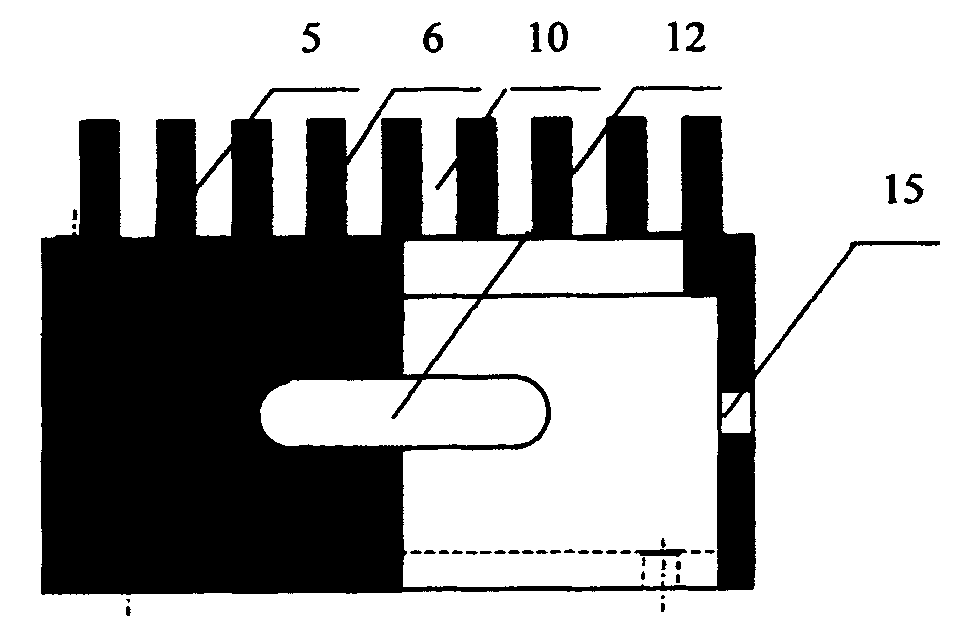
本发明是这样实现的,见图3、图4、图5、图6所示,在夹具箱体5的上部设置若干个相互等距的静夹口6,若干个动夹口7插入到动夹口7的保持架8上面的插槽9中,动夹口7是具有一定弹性的薄片,然后将这一部分整体自夹具箱体5下部放入其中,各个动夹口7的上端穿入各个静夹口6之间的狭缝10中,各个动夹口7与各个静夹口6的上端齐平,将两个滑块11分别放入夹具箱体5两侧面的滑槽12中,并分别固定于保持架8的两个侧面上,滑块11可以在滑槽12中在一定行程内来回平移,在每个滑块11的一端有一个推挡13,在推挡13与滑槽12之间放入一个施力弹簧14,在夹具箱体5的两个端面中的一个开一个丝孔15,自此旋入一个丝顶用来推移保持架8,可压缩施力弹簧14,在动夹口7与静夹口6之间形成缝隙,将待镀膜的解理条插入该缝隙中,之后,将丝顶旋出一定程度,此时,由施力弹簧14施以的弹力通过具有弹性的动夹口7作用于解理条上,实现柔性、稳固、准确的夹持。The present invention is realized in this way, as shown in Fig. 3, Fig. 4, Fig. 5, and Fig. 6, several mutually equidistant static jaws 6 are arranged on the upper part of the fixture box 5, and several dynamic jaws 7 are inserted into the dynamic jaws. In the
本发明的效果在于,由于本发明之夹具仍开有若干个夹口,所以仍可以进行批量操作。本发明之柔性有两层含义,一是它可以适用于一定厚度范围的解理条;二是解理条所受到的夹持力是一种弹力。这是因为在静夹口6之间留有较大空间,因而在动夹口7与静夹口6之间也就存在较大回转空间,再加上施以的夹持力来自施力弹簧14,并且还是通过具有弹性的动夹口7间接施加,而且还可通过调整丝顶来调整所施加的力的大小,因此,所说的柔性便产生了,因而也就实现了无损伤、宽厚度范围、稳固、操作简便准确夹持解理条的发明目的。又由于不管有怎样厚度差别的解理条最后都是紧靠在静夹口6的侧壁上保持垂直状态,紧紧贴在解理条两侧的静夹口6、动夹口7不仅起到夹持作用,还有遮蔽作用,从而从根本上防止了将蒸镀材料镀在解理条的P、N两电极上,克服了上文介绍的现有技术的最大弊端。The effect of the present invention is that batch operation can still be performed because the clamp of the present invention still has several jaws. The flexibility of the present invention has two meanings, one is that it can be applied to the cleavage strip in a certain thickness range; the other is that the clamping force received by the cleavage strip is a kind of elastic force. This is because there is a large space between the static jaws 6, so there is a large turning space between the dynamic jaws 7 and the static jaws 6, and the clamping force applied comes from the force spring 14, and it is applied indirectly through the elastic movable jaw 7, and the size of the applied force can also be adjusted by adjusting the wire top. Therefore, the so-called flexibility is produced, thus realizing no damage, wide and thick The purpose of the invention is to clamp the cleavage strip accurately, within a wide range of degrees, stable, easy and convenient to operate. No matter how the cleavage bar of thickness difference is arranged at last all is to be close to the sidewall of static jaw 6 and keep vertical state, be closely attached to the static jaw 6 of cleavage bar both sides, dynamic jaw 7 not only play In addition to the clamping function, there is also a shielding function, which fundamentally prevents the evaporation material from being plated on the P and N electrodes of the cleavage strip, and overcomes the biggest drawback of the prior art introduced above.
附图说明Description of drawings
图1是现有技术之夹具示意图。图2是对现有技术存在的问题所做分析示意图。图3是本发明之夹具主体三视图。图4是本发明之夹具动夹口保持架主、俯视图。图5是本发明之夹具动夹口主、左视图。图6是本发明之夹具滑块主、俯视图。图7是本发明之夹具夹口框主、左视图。图8是本发明之夹具动夹口插槽形态放大示意图。图9是本发明之夹具动夹口上端做倒角处理及动夹口、解理条、静夹口三者状态关系示意图。图10是本发明之夹具动夹口、解理条、静夹口三者状态关系的一种特殊形态示意图。Fig. 1 is a schematic diagram of a fixture in the prior art. Fig. 2 is a schematic diagram for analyzing the problems existing in the prior art. Fig. 3 is a three-view view of the fixture main body of the present invention. Fig. 4 is the main and top view of the clamp movable jaw retainer of the present invention. Fig. 5 is the main and left side views of the movable jaw of the clamp according to the present invention. Fig. 6 is the main and top view of the clamp slider of the present invention. Fig. 7 is the front and left side views of the clamp jaw frame of the present invention. Fig. 8 is an enlarged schematic diagram of the shape of the movable jaw slot of the fixture according to the present invention. Fig. 9 is a schematic diagram of the chamfering treatment on the upper end of the movable jaw of the fixture according to the present invention and the state relationship among the dynamic jaw, the cleavage strip and the static jaw. Fig. 10 is a special form schematic diagram of the state relationship among the movable jaw, the cleavage bar and the static jaw of the clamp of the present invention.
具体实施方式 Detailed ways
夹具主体包括夹具箱体5、静夹口6部分采用不锈钢或者黄铜材料制作,静夹口6厚度为1.5毫米,静夹口6之间的距离为1.5~4.0毫米。设计一种夹口框16,见图7所示,由黄铜材料制作,框内尺寸与各静夹口6的分布的周边尺寸相同,其高度也与静夹口6的高度相同,在插入完解理条之后,将夹口框16套在静夹口6周边,并用螺丝固定在夹具箱体5上,其作用有两个,一是防止解理条从两侧滑落,进一步固定解理条;二是防止解理条暴露在外的侧端面被镀上膜层。动夹口7采用0.1~0.2毫米厚的磷青铜板或者聚四氟乙烯板制作。保持架8采用黄铜材料制作,上面的插槽9的形态见图8所示,它做θ角倾斜,如2°,使得插入插槽9中的动夹口7随着丝顶的缓慢旋出而倾斜接近解理条,由线接触渐进发展为面接触,接触面由小到大,无损伤地夹持解理条,施加到解理条上的力一般控制在0.01千克力为佳。在保持架8上,对应每一个插槽9,都有一个有着圆锥形头部的动夹口7固定丝顶17,当把动夹口7插入插槽9中后,旋紧该固定丝顶17即可将动夹口7固定住。各个固定丝顶17分散分布在保持架8的底部。动夹口7在插槽9中的固定方式还可以是,先在动夹口7插入插槽9的部分两侧各冲一个微小凸起,由于插槽9的宽度略比动夹口7的厚度大一些,因此,当将动夹口7插入到插槽9中时,靠这两个微小凸起就能使动夹口7胀紧在插槽9中。滑块11也采用黄铜材料制作,它在滑槽12中的行程视静夹口6之间的距离而定,可在2.0~4.5毫米范围内确定。施力弹簧14是一种耐热弹簧。在将解理条插入静夹口6和动夹口7之间的缝隙时,应将夹具箱体5翻过来,静夹口6朝下,放在一个平面上,同时也要使动夹口7也都落在这一平面上,见图9所示,插入的解理条18其待镀膜腔面19与静夹口6、动夹口7的端面处在同一平面上,静夹口6、动夹口7既起到夹持解理条18的作用,也起到掩蔽解理条18N、P电极的作用。不过,为防止在从夹具中取下解理条18时因粘连而破坏有源区20腔面所镀膜层,可将动夹口7上端面靠解理条18有源区20一侧倒一θ′角,如45°。为解决这一问题,也可采取以下设计,见图10所示,将夹具箱体5两端的静夹口6设计出一个台阶21,它高出其它静夹口6上端面20~50微米,装夹时使解理条18的腔面19与该台阶21高度相等,而其它静夹口6、动夹口7的上端面都低于20~50微米,避免因粘连而破坏有源区20腔面所镀膜层。The main body of the fixture includes the fixture box 5 and the static jaws 6, which are made of stainless steel or brass. The thickness of the static jaws 6 is 1.5 mm, and the distance between the static jaws 6 is 1.5-4.0 mm. Design a kind of
Claims (10)
Priority Applications (1)
| Application Number | Priority Date | Filing Date | Title |
|---|---|---|---|
| CNB2004100297122A CN1300373C (en) | 2004-03-24 | 2004-03-24 | Flexible clamp in use for filming face of cavity of semiconductor laser |
Applications Claiming Priority (1)
| Application Number | Priority Date | Filing Date | Title |
|---|---|---|---|
| CNB2004100297122A CN1300373C (en) | 2004-03-24 | 2004-03-24 | Flexible clamp in use for filming face of cavity of semiconductor laser |
Publications (2)
| Publication Number | Publication Date |
|---|---|
| CN1563476A CN1563476A (en) | 2005-01-12 |
| CN1300373C true CN1300373C (en) | 2007-02-14 |
Family
ID=34480976
Family Applications (1)
| Application Number | Title | Priority Date | Filing Date |
|---|---|---|---|
| CNB2004100297122A Expired - Fee Related CN1300373C (en) | 2004-03-24 | 2004-03-24 | Flexible clamp in use for filming face of cavity of semiconductor laser |
Country Status (1)
| Country | Link |
|---|---|
| CN (1) | CN1300373C (en) |
Families Citing this family (5)
| Publication number | Priority date | Publication date | Assignee | Title |
|---|---|---|---|---|
| CN103225069B (en) * | 2013-04-28 | 2015-05-20 | 上海华力微电子有限公司 | Metal plating tray of metal evaporation plating apparatus |
| CN105938976B (en) * | 2016-03-08 | 2019-03-22 | 北京工业大学 | Semiconductor laser cavity surface coating fixture |
| JP7206962B2 (en) * | 2019-01-31 | 2023-01-18 | 三菱電機株式会社 | Semiconductor substrate separation method and separation jig |
| CN113604783A (en) * | 2021-07-30 | 2021-11-05 | 上海米蜂激光科技有限公司 | Special fixture for coating film on outer surface of tubular or rod-shaped optical element |
| CN117535641B (en) * | 2022-08-02 | 2026-02-03 | 江苏菲沃泰纳米科技股份有限公司 | Earphone fixing assembly, earphone coating jig and earphone coating jig set |
Citations (3)
| Publication number | Priority date | Publication date | Assignee | Title |
|---|---|---|---|---|
| WO1999056306A1 (en) * | 1998-04-24 | 1999-11-04 | Steag Hamatech Ag | Device for fixing substrates |
| JP2001076954A (en) * | 1999-08-31 | 2001-03-23 | Rhythm Watch Co Ltd | Coil-winding machine |
| CN1422978A (en) * | 2002-12-13 | 2003-06-11 | 中国科学院上海微系统与信息技术研究所 | Clamp of contactless fixture mode for cavity surface evaporating coating of semiconductor laser |
-
2004
- 2004-03-24 CN CNB2004100297122A patent/CN1300373C/en not_active Expired - Fee Related
Patent Citations (3)
| Publication number | Priority date | Publication date | Assignee | Title |
|---|---|---|---|---|
| WO1999056306A1 (en) * | 1998-04-24 | 1999-11-04 | Steag Hamatech Ag | Device for fixing substrates |
| JP2001076954A (en) * | 1999-08-31 | 2001-03-23 | Rhythm Watch Co Ltd | Coil-winding machine |
| CN1422978A (en) * | 2002-12-13 | 2003-06-11 | 中国科学院上海微系统与信息技术研究所 | Clamp of contactless fixture mode for cavity surface evaporating coating of semiconductor laser |
Also Published As
| Publication number | Publication date |
|---|---|
| CN1563476A (en) | 2005-01-12 |
Similar Documents
| Publication | Publication Date | Title |
|---|---|---|
| CN1300373C (en) | Flexible clamp in use for filming face of cavity of semiconductor laser | |
| TW201027191A (en) | Plane type light source device and image display device having the same | |
| CN103090323A (en) | Diaphragm positioning structure and backlight module thereof | |
| EP1657756A3 (en) | Sheet for optical semiconductor element encapsulation and process for producing optical semiconductor device with the sheet | |
| US5058280A (en) | Scroll saw blade holder | |
| CN101215101A (en) | Flat glass substrate thinning jig | |
| TWI234750B (en) | Surface light source device and image display device | |
| EP1439575A3 (en) | Semiconductor device with a lead frame and method of manufacturing the same | |
| TWI255866B (en) | Plating method and plating apparatus | |
| CN110512184B (en) | Substrate clamping device and vapor deposition equipment | |
| CN209434163U (en) | Chip manufacture multi-functional clamp | |
| WO2017148046A1 (en) | Disassembly tool | |
| TWM356138U (en) | Side-emitting backlight module | |
| CN219417224U (en) | SERS detects inserted sheet mechanism | |
| WO2017121081A1 (en) | Light guide plate, backlight source and display device | |
| CN208351092U (en) | Square filter clamp and square filter assembly | |
| CN105116313B (en) | Simple stress bringing device and strain MOS chip output characteristics method of testings | |
| JP2002171077A (en) | Equipment attaching device | |
| CN108063109A (en) | A kind of method for cleaning the gaily decorated basket of chip and being cleaned to chip | |
| TW201241326A (en) | Clamp apparatus | |
| CN116461187A (en) | Fitting jig and fitting device | |
| CN221765811U (en) | A grating adjustment mechanism | |
| CN221696618U (en) | A glass clamp structure | |
| CN206396321U (en) | A kind of disk optical element is without rib coating clamp | |
| CN221580683U (en) | Automatic clamping test tube rack |
Legal Events
| Date | Code | Title | Description |
|---|---|---|---|
| C06 | Publication | ||
| PB01 | Publication | ||
| C10 | Entry into substantive examination | ||
| SE01 | Entry into force of request for substantive examination | ||
| C14 | Grant of patent or utility model | ||
| GR01 | Patent grant | ||
| C17 | Cessation of patent right | ||
| CF01 | Termination of patent right due to non-payment of annual fee |
Granted publication date: 20070214 |