CN1284901A - Apparatus and method for pulsed magnetic forming of dish from planar plate - Google Patents
Apparatus and method for pulsed magnetic forming of dish from planar plate Download PDFInfo
- Publication number
- CN1284901A CN1284901A CN98813440.3A CN98813440A CN1284901A CN 1284901 A CN1284901 A CN 1284901A CN 98813440 A CN98813440 A CN 98813440A CN 1284901 A CN1284901 A CN 1284901A
- Authority
- CN
- China
- Prior art keywords
- equipment
- profiled surface
- coil
- dish
- mould
- Prior art date
- Legal status (The legal status is an assumption and is not a legal conclusion. Google has not performed a legal analysis and makes no representation as to the accuracy of the status listed.)
- Pending
Links
Images


Classifications
-
- B—PERFORMING OPERATIONS; TRANSPORTING
- B21—MECHANICAL METAL-WORKING WITHOUT ESSENTIALLY REMOVING MATERIAL; PUNCHING METAL
- B21D—WORKING OR PROCESSING OF SHEET METAL OR METAL TUBES, RODS OR PROFILES WITHOUT ESSENTIALLY REMOVING MATERIAL; PUNCHING METAL
- B21D26/00—Shaping without cutting otherwise than using rigid devices or tools or yieldable or resilient pads, i.e. applying fluid pressure or magnetic forces
- B21D26/14—Shaping without cutting otherwise than using rigid devices or tools or yieldable or resilient pads, i.e. applying fluid pressure or magnetic forces applying magnetic forces
-
- Y—GENERAL TAGGING OF NEW TECHNOLOGICAL DEVELOPMENTS; GENERAL TAGGING OF CROSS-SECTIONAL TECHNOLOGIES SPANNING OVER SEVERAL SECTIONS OF THE IPC; TECHNICAL SUBJECTS COVERED BY FORMER USPC CROSS-REFERENCE ART COLLECTIONS [XRACs] AND DIGESTS
- Y10—TECHNICAL SUBJECTS COVERED BY FORMER USPC
- Y10S—TECHNICAL SUBJECTS COVERED BY FORMER USPC CROSS-REFERENCE ART COLLECTIONS [XRACs] AND DIGESTS
- Y10S72/00—Metal deforming
- Y10S72/707—Magnetism
-
- Y—GENERAL TAGGING OF NEW TECHNOLOGICAL DEVELOPMENTS; GENERAL TAGGING OF CROSS-SECTIONAL TECHNOLOGIES SPANNING OVER SEVERAL SECTIONS OF THE IPC; TECHNICAL SUBJECTS COVERED BY FORMER USPC CROSS-REFERENCE ART COLLECTIONS [XRACs] AND DIGESTS
- Y10—TECHNICAL SUBJECTS COVERED BY FORMER USPC
- Y10T—TECHNICAL SUBJECTS COVERED BY FORMER US CLASSIFICATION
- Y10T29/00—Metal working
- Y10T29/49—Method of mechanical manufacture
- Y10T29/49803—Magnetically shaping
Landscapes
- Physics & Mathematics (AREA)
- Fluid Mechanics (AREA)
- Engineering & Computer Science (AREA)
- Mechanical Engineering (AREA)
- Shaping Metal By Deep-Drawing, Or The Like (AREA)
- Windings For Motors And Generators (AREA)
- Manufacturing Cores, Coils, And Magnets (AREA)
Abstract
An electromagnetic forming apparatus for forming an essentially planar metal plate into a dish having a three-dimensional pattern, is provided. The apparatus comprises a mould having a forming surface with a contour corresponding to said three-dimensional pattern; a forming coil device; and an electric discharge circuitry for discharging a short and intense electric current pulse through the forming coil device to yield a pulsed magnetic forming (PMF) force for deforming said plate.
Description
Invention field
The present invention generally belongs to pulsed magnetic forming (PMF) field, and provides a set of equipment and method for this kind shaping.Particularly, the present invention relates to flat board is made the PMF technology of dish.
Background technology
There are many processing methods can both make metal object form the shape that people want.For example, adopt the method for casting the metal of liquid condition can be processed into conceivable net shape.But this type of processing method can only be applied to some particular case, and in addition, it need consume a large amount of energy, complicated and expensive heating and cooling equipment.
Metal has certain pliability, and corresponding, metal works also can become another kind of shape by a kind of shape sometimes.For example, utilize the mechanical stamping machine, can process and cut metallic plate and make it to form the various shapes of wanting.In order to obtain the finished article that essential pressure is wanted with formation, this pressing requires to have the very main equipment of costliness of a cover.
PMF is a kind of like this processing method, acted on by pulsed magnetic field, and metal works or certain a part of rapid movement wherein make workpiece deformation.An advantage of PMF processing method is exactly an energy loss minimum in the process, thereby does not need the heating of metal goods, and it is very little perhaps to add heat.In addition, adopt other forming techniques to tend to the vestige of the instrument that stays, and this processing method does not just have this shortcoming.The PMF processing method adopts one or one group of discharging capacitor, and a form-wound coil usually also has the high-intensity magnetic field that a magnetic forming device forms transition.The very large magnetic field of formed intensity in the PMF processing method is to be stored in the result that the electric energy in the capacitor is emitted fast by form-wound coil.The eddy current that induction produces in workpiece has formed a kind of magnetic repulsion effect between metallic article and form-wound coil, make the metallic article distortion.
About the background of the technical equipment of utilizing PMF processing method processing metal goods in the past and method can be in U.S.Patent 3,654,787,3,961,739,4,170,887,4,531,393,4,807,731,5,353,617 and 5,442,846 and the open No.WO97/22426 of PCT application in find.
The metal plate on a plane is processed into the metal object of given shape, both had been necessary sometimes to process one flat plate, thereby also be necessary to repair the border that the metalwork after the processing is determined at its edge in order to obtain a threedimensional model of wanting.
One object of the present invention just is to provide a kind of PMF former and method that metal plate is deformed into the dish of conceivable threedimensional model and shape.
Summary of the invention
First aspect of the present invention is exactly, and a cover electro-magnetic forming equipment is provided, and can will be metal plate distortion the becoming dish that conceivable 3D shape is arranged on plane originally.Its application in the process of utilizing dull and stereotyped teledish of making artificial satellite is exactly a nonrestrictive exemplary.
According to an embodiment, this equipment comprises:
Mould, the profile of its profiled surface is identical with described threedimensional model shape, the borderline phase correspondence of its edge and dish, and the edge is to determine by the sidewall that is substantially perpendicular to profiled surface;
The form-wound coil device, opposed and with described profiled surface near profiled surface, and periphery extends to described border;
Flat board, the boundary is between form-wound coil and described profiled surface; And
Discharge loop, the strong current pulse of a weak point of discharge generation forms pulse magnetic (PMF) power that is shaped by form-wound coil and makes described plate deformation.
According to one embodiment of the invention, form-wound coil is made up of single coil member.And according to another embodiment of the invention, form-wound coil can comprise that has two or more component arrays.Member in the form-wound coil of being made up of two or more coil members generally is concentric.Composition according to this embodiment equipment comprises:
Mould, the profile of its profiled surface is identical with described threedimensional model shape;
The form-wound coil device, the opposed and the most approaching described profiled surface with described profiled surface, its composition comprises two or more coil members; Dull and stereotyped boundary is between form-wound coil and described profiled surface; And
Discharge loop is made up of two or more discharge loops, and each coil member links to each other with a loop, and discharge produces short strong current pulse and makes described plate deformation by form-wound coil formation pulsed magnetic forming (PMF) power.
In the occasion of the form-wound coil of being made up of two or more coil members, discharge loop can regularly send current impulse simultaneously by all coil members; Perhaps more primely, can arrange discharge time according to the discharge order of prior decision.For example, in the example of the form-wound coil of being made up of several concentric coil members, the order of discharge can be such, by centering coil coil expansion to the periphery; Or in the other direction, promptly expand to the center from peripheral coil; Perhaps according to other discharge order of certain conceivable threedimensional model design.
According to another embodiment of the invention, the composition of form-wound coil comprises one or more coil members, these members can along be substantially perpendicular to metal plate the axis on definite plane move.The composition of the equipment of this embodiment comprises:
Mould, the profile of its profiled surface is identical with described threedimensional model shape;
The form-wound coil device is made up of one or more coil members, can along be substantially perpendicular to metal plate the axis on definite plane move;
Discharge loop is made up of two or more discharge loops, and each loop links to each other with a coil member, and discharge produces short strong current pulse and makes described plate deformation by form-wound coil formation pulse magnetic (PMF) power that is shaped.
According to the characteristics of the form-wound coil in the equipment of the present embodiment, form by two or more coil members that can move along described axis respectively exactly.Dull and stereotyped deformation process may be made up of two or more steps.At first be positioned initial position, utilize PMF power to make the dull and stereotyped part distortion that takes place, then the moving coil member to mobile corresponding axial location through the flat board of preliminary deformation.Then, send the PMF pulse once more and make dull and stereotyped further distortion, this step can repeat until forming last shape.
According to another embodiment of the invention, the formation of form-wound coil device can comprise one or more coil members, and its size only covers the part of the flat board that will form processing.Composition according to the equipment of this embodiment comprises:
Mould, the profile of its profiled surface is identical with described threedimensional model shape;
The form-wound coil device, opposed and with described profiled surface near profiled surface, its composition comprises one or more coil members, its size has only covered the part that will form the flat board of processing, and this or more coil member can move on the plane that is parallel to dull and stereotyped determined plane;
Discharge loop, the short strong current pulse of discharge generation forms pulsed magnetic forming (PMF) power by form-wound coil makes described plate deformation.
According to this embodiment, at first the form-wound coil member is placed on an original position, produce the PMF pulse and make dull and stereotyped part generation local deformation facing to member, it is relative with another part of the flat board of next PMF pulse processing then the form-wound coil member to be moved to another position.Repeat these steps and form described threedimensional model until whole plate deformation.
Mould, according to an embodiment, its composition comprises one or more and the corresponding recess of described threedimensional model shape.Usually, according to this embodiment, mould has a central concave part, determines the central concave part of dish, and as its template.In deformation process, dull and stereotyped each several part will move quickly into sunk part, and the gas that keeps in the mould, as air, can hinder mobile, thereby can't form conceivable threedimensional model.Therefore, in one embodiment, the gas discharge tube is set the gas of recess in the forming process can be discharged.In order to get rid of the gas of recess, these conduits can link to each other with a vacuum source.
According to another embodiment, the formation of profiled surface comprises the protrusion of determining described threedimensional model.According to other embodiments of the present invention, the formation of profiled surface comprises at least one depression and at least one protrusion, and they determine described threedimensional model jointly.
According to another aspect of the present invention, a kind of electromagnetic forming method is provided, can make the metal plate of general closed planar be deformed into the dish of a threedimensional model shape.According to one of them embodiment, the composition of this method comprises:
(a) provide a mould, the profile of its profiled surface is identical with described threedimensional model shape, the borderline phase correspondence of its edge and dish, and this edge is to determine by the sidewall that is substantially perpendicular to profiled surface.
(b) metal plate is placed on the profiled surface top of mould;
(c) the form-wound coil device that provides a cover to link to each other with discharge loop is placed on the top of metal plate to it, and form-wound coil extends beyond the border of described profiled surface;
(d) heavy current short pulse of discharge generation is sheared flat board and other parts of described flat board is produced masterpieces in order to guaranteeing the forming determined shape of described mould by described coil along described border, thereby obtains described dish.
According to another embodiment, the composition of method comprises:
(a) provide a mould, the profile of its profiled surface is identical with described threedimensional model shape, the borderline phase correspondence of its edge and dish, and this edge is to determine by the sidewall that is substantially perpendicular to profiled surface.
(b) metal plate is placed on the profiled surface of mould;
(c) the form-wound coil device that provides a cover to link to each other with discharge loop is placed on it on the metal plate;
(d) produce the heavy current short pulse by described two or more coil discharges and make plate deformation.
According to another embodiment, the composition of method comprises:
(a) provide a mould, the profile of its profiled surface is identical with described threedimensional model shape;
(b) metal plate is placed on the profiled surface of mould;
(c) provide a cover form-wound coil device, its formation comprises two or more form-wound coil members, and each member all links to each other with a discharge loop, and it is placed on the metal plate;
(d) heavy current short pulse of discharge generation makes described metal plate distortion by described two or more coil members;
(e) move the corresponding position of shape of the flat board after described coil member to and the distortion along described axis, repeating step (d);
(f) repeating step (e) is until forming described threedimensional model shape.
According to a further embodiment of the present invention, the composition of method comprises:
(a) provide a mould, the profile of its profiled surface is identical with described threedimensional model shape;
(b) metal plate is placed on the profiled surface of mould;
(c) provide a cover form-wound coil device, its formation comprises one or more form-wound coil members, its size only covers the part of the flat board that will form processing, and this or more coil member can move on the plane that is parallel to dull and stereotyped determined plane, and the form-wound coil device is placed on the metal plate;
(d) heavy current short pulse of discharge generation makes the part distortion of described metal plate facing to described profiled surface by described coil;
(e) laterally move described form-wound coil device, and repeating step (d);
(f) repeating step (e) is until obtaining described threedimensional model.
To come this patent is described by some non-limiting specific embodiments of introducing described in the accompanying drawing below.
Brief description
Fig. 1 is according to one embodiment of the invention, before the processing metal flat board, and the schematic diagram of a cross section by former.
Fig. 2 is the top view of the coil of equipment among Fig. 1.
Fig. 3 is the schematic diagram of forming process.
Fig. 4 is the cross sectional representation through the dish after the described technology of equipment utilization shapes among employing Fig. 1.
Fig. 5 A is a cross sectional representation according to the former of another embodiment of the invention.
Fig. 5 B has shown the situation of equipment after dish is shaped among Fig. 5 A.
Fig. 6 is the top view according to the form-wound coil device in another embodiment of the invention, and the composition of this device comprises one group of three form-wound coil member.
Fig. 7 is the top view according to the form-wound coil device in another embodiment of the invention, and the composition of this device comprises three coil members, and each member is made of several windings respectively.
Fig. 8 A-8C is according to another embodiment of the invention, is the cross sectional representation of form-wound coil device, and the coil member number of this device more (having 3 in this specific embodiments), each member are continuous with different discharge loops respectively.Fig. 8 A-8C has illustrated equipment situation in each step in deformation process.
Fig. 9 A-9C is according to another embodiment of the invention, it is the cross sectional representation of form-wound coil device, the coil member number of this device more (having 3 in this specific embodiments), each member all can move along the axis perpendicular to the determined plane of flat board separately.Fig. 9 A-9C has illustrated equipment situation in each step in deformation process.
Figure 10 A and Figure 10 B are according to the initial period (Figure 10 A) of the equipment in another embodiment of the invention in the dish forming process and the situation of terminal stage (Figure 10 B).
Figure 11 illustrates the equipment in another embodiment of the invention, and wherein the shape of mould is asymmetric.
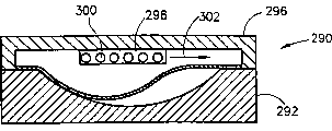
Figure 12 A-12B is the cross sectional representation by a set of equipment of the present invention, and coil member wherein can move on the plane that is parallel to dull and stereotyped determined plane.Figure 12 A-12C has shown in the dish forming process situation of equipment in three consecutive steps.
The detailed description of specific embodiments
At first describe with reference to figure 1, shown in Fig. 1 be one the cover totally by 10 equipment that mark, its composition comprises mould 12, form-wound coil assembly 14, metal plate 16 is installed between the two.
Around, the upper surface 34 of member, lower limb 20 also has the inner margin portion 36 through chamfering to mould 12 by 32 of annular construction members, is used for receiving and holding the waste material of shearing (seeing below).
Coil 40 is electrically connected with discharge loop 50, comprises capacitor group 52 and big electric current repid discharge switch 54 in the loop, and both itself are known.An example of this type of discharge switch is exactly controlled vacuum arrester, announces that as Israel patent application No.119826 and in the appropriate section of PCT application No.PCT/IL97/00383 like that, switch 54 is controlled by control loop 55.
In operating process, as shown in Figure 3, switch 54 closures, taking this electric current emits fast by coil 40 generation pulsed magnetic force, force dull and stereotyped 16 each several parts to move apace: to be stacked in the each several part generation deformation on depression 24 and the annular groove 26, thereby present the threedimensional model shape of determining therefrom, dull and stereotyped 16 form peripheral edge portions 60 is sheared on the peripheral edge 20 that gets off to drop on mould 12.Therefore, dish 62 as shown in Figure 4, has a central concave 64, and the limit skirt 66 of band connected in star 68 has just formed.This dish can be used as, and for example, antenna is especially for the satellite communication aspect.Annular construction member 32 can upwards push away so that will be sheared the part 60 of getting off and dispose.
Now Fig. 5 A-5B is described, these figure explanation be equipment according to another embodiment of the invention, totally by 80 marks.The composition of equipment comprises mould 82 and form-wound coil assembly 84, and metal plate 86 is contained between them, also has discharge loop 88.The equipment 80 among Fig. 5 A and the 5B and the main difference of the equipment 10 among Fig. 1 are mould, and do not lie in recessed or protruding.In addition, equipment operate in essence with Fig. 1 and 3 explanation in introduce the same.Fig. 5 B, expression be dull and stereotyped 86 to become dish equipment after 90s through the processing that are shaped.Because from essence, identical described in operation and Fig. 1-3 explanation, so no longer repeat to introduce, the reader can be with reference to description above.
Fig. 6 represents is equipment according to another embodiment of the invention.In this embodiment, form-wound coil device 100 is made up of one group of 3 form-wound coil member 102,104 and 106.The composition of discharge loop 110 comprises capacitor group 112,3 big electric current repid discharge switches 114,116 and 118 under controller 120 control, each switch respectively with coil member 102,104 and 106 in one link to each other resistor 122,124 and 126 in addition.Such loop allows the fast current pulse to discharge by each member in the coil member 102,104 and 106 independently respectively with required operating sequence.For example, be made of in the example of coil device 3 ceoncentrically wound coil members, the pattern of discharge can be by centering coil 102, then by coil 104, at last by coil member 106 from current discharge.
Should be appreciated that 3 coil member combinations being introduced among Fig. 6 are an example just, and this combination can be made of the coil member of any conceivable number, for example 2 to 10.
Be also to be understood that the discharge loop shown in Fig. 6 is an example, and discharge can adopt multiple different circuit to realize by different coil members in order.
Among Fig. 7, simple declaration the form-wound coil device 130 of another embodiment of the invention.The composition of form-wound coil device 130 comprises 3 coil members 132,134 and 136, and each member is formed by several coil windings.In this example, each coil member has two coil windings, although this just individual example, and the number of the winding in each coil member can be arbitrary decision, particularly between 2 to 20.The coil of each coil member links to each other with discharge/control loop 138.
What Fig. 8 A-8C introduced is the equipment of another embodiment of the invention.In itself, the equipment of being introduced among this equipment and Fig. 1 is similar, main difference is form-wound coil device 150, it is by (3-152 of a plurality of coil members, 154,156, as shown in the figure, can form by the absolute coil member of any other numbers although should be understood that the form-wound coil device).Form-wound coil device 150 is supported by gripper shoe 160.Each member 152,154 and 156 links to each other with 166 with corresponding discharge loop 162,164, all under the control of controller 168.
In this specific embodiment, discharge loop 162,164 and 166 discharge generation strong current pulse fast sequentially regularly, from central component 156 (Fig. 8 A), (shown in arrow 170) extending transversely, discharge is that coil member 152 (Fig. 8 C) forms the dish 172 with mould 174 determined threedimensional model shapes by coil member 154 (Fig. 8 B) at last.
What Fig. 9 A-9C introduced is the equipment 180 of another embodiment of the invention.The composition of this equipment comprises, mould 182, and its depression 184 has been determined the threedimensional model shape of the formed dish of dull and stereotyped 186 distortion, dull and stereotyped 186 link to each other with peripheral supporting walls 188.
Form-wound coil 190 is made up of a plurality of coil members, has 3-192,194 and 196 in this specific embodiments.Each coil member can move along the axis perpendicular to the definite plane of dull and stereotyped institute, respectively by movably back-up block 202,204 that links to each other and 206 supports.Similar to embodiment shown in Fig. 8 A-8C, each coil member links to each other the control of controlled device 218 with different discharge loop 212,214 with 216.
Fig. 9 A explanation be, be accompanied by the PMF current discharge by coil member 192, make the dull and stereotyped equipment that takes place after the initial distortion by coil member 194 and 196 then, obtain the flat board 186 of part distortion by this, shown in Fig. 9 B.Coil member can move towards the flat board that is out of shape along axis then, more approaches dull and stereotyped position so that each member arrives one, and then PMF discharges again in an orderly manner by different coil members, and is described similar with preamble.So repeat, flat board is badly deformed and forms dish 224 (Fig. 9 C).
What Figure 10 A and Figure 10 B introduced is the equipment of another embodiment of the invention, totally with 230 marks.The composition of this equipment comprises mould 232, on depression 234 and gripper shoe 236 is arranged.Form-wound coil device, general reference numeral are 240, are made up of some coil members, have 3-242,244 and 246, shown in this specific embodiments, are supported by back-up block 250.Different members is performed such steric, and they can follow the profile corresponding to depression 234 usually.Deformation process in this example is to pass through one or more coil blocks by the PMF electric current according to certain sequence discharge, moves the monoblock coil member along the axis direction shown in arrow 252 then, finally is deformed into dish 254 until dull and stereotyped 236.
Figure 11 has explained similar with embodiment shown in Figure 10 A in essence equipment 260 of a cover, and still, different with the depression 264 of symmetry is the depression 264 in the mould 262 is asymmetric.Accordingly, under the support of back-up block 280, there is a corresponding general locus of profile with depression 264 each coil member 272,274 and 276 locus.
Figure 10 A, 10B and 11 for the terseness of describing, has omitted electronic loop.
To introduce Figure 12 A-21C now, wherein explanation is equipment 290 according to another embodiment of the invention.The composition of this complete equipment comprises mould 292, on have the depression 294, back-up block 296 links to each other with form-wound coil device 298.Form-wound coil device 298 comprises coil 300, can move horizontally, shown in arrow 302.It should be noted that in principle, form-wound coil device 298 also can move along the axis perpendicular to plane, metal plate place.
The form-wound coil device is arranged on the top of a part of flat board 304, the PMF electric current flows through coil (discharge loop does not draw), and coil device is moved to another position then, again discharge generation PMF electric current, move again, become dish 306 until whole plate deformation so repeatedly.
Claims (36)
1. an electro-magnetic forming equipment can make the metal plate that is essentially the plane be deformed into the dish of threedimensional model shape, and its composition comprises:
Mould, the profile of its profiled surface is identical with described threedimensional model shape, the borderline phase correspondence of its edge and dish, the edge is by determining perpendicular to the sidewall of profiled surface originally;
The form-wound coil device, relative with described profiled surface and near profiled surface, and extend to outside the described border; Dull and stereotyped boundary is between form-wound coil and described profiled surface;
Discharge loop, the strong current pulse that discharge generation is short forms pulsed magnetic forming (PMF) power by form-wound coil and makes described plate deformation.
2. equipment as claimed in claim 1, wherein, the formation of described profiled surface comprises the corresponding depression of one or more and described threedimensional model shape.
3. equipment as claimed in claim 2, wherein, the profiled surface of described mould has a central concave position, determines the central concave part of dish, and has played template action.
4. equipment as claimed in claim 3, wherein, described central concave has the conduit of emission gases.
5. equipment as claimed in claim 4, wherein, described conduit links to each other with the vacuum source of the gas that is used to remove recess.
6. equipment as claimed in claim 1, wherein, the formation of described profiled surface comprises the projection of determining described threedimensional model shape.
7. equipment as claimed in claim 1, wherein, the formation of described profiled surface comprises at least one depression and at least one protrusion, determines described threedimensional model shape.
8. as the equipment in above-mentioned arbitrary claim, has the skirt section of central concave part and outer rim.
9. equipment as claimed in claim 8, wherein, the profiled surface profile comprises the required circumferential annular groove in formation skirt section, dish edge.
10. equipment as claimed in claim 9, wherein, the formation of form-wound coil device comprises two or more coil members, each all links to each other with independent discharge loop.
11. the equipment described in above-mentioned arbitrary claim, wherein, coil device has one or more form-wound coil members, all can move along the axis that is substantially perpendicular to the determined plane of metal plate.
12. as the equipment of claim 11, wherein, the formation of coil device comprises two or more members, can move along described axis respectively.
13. as the equipment of claim 12, wherein, after plate deformation, coil member be moved to be out of shape after the corresponding position of shape of flat board.
14. as the equipment of claim 12 or 13, wherein, coil member is concentric.
15. as the equipment of above-mentioned any claim, wherein, the composition of form-wound coil device comprises the coil member that is formed by the two or more coils that fit together.
16. an electro-magnetic forming equipment makes the dish that is deformed into the threedimensional model shape originally for the metal plate on plane, its composition comprises:
Mould, the profile of its profiled surface is identical with described threedimensional model shape;
The form-wound coil device is relative with described profiled surface and near profiled surface, its composition comprises two or more coil members; Dull and stereotyped boundary is between form-wound coil and described profiled surface; And
Discharge loop is made up of two or more loops, and each links to each other each loop with a coil member, and the strong current pulse that discharge generation is short forms pulsed magnetic forming (PMF) power by form-wound coil and makes described plate deformation.
17., wherein, carry out according to pre-determined discharge order by the discharge of each coil member through relevant apparatus as the equipment of claim 16.
18. as the equipment of claim 16 or 17, wherein, each member can move along the axis that is substantially perpendicular to the determined plane of metal plate.
19. as the equipment of claim 18, wherein, each described member can move along described axis separately.
20. as the equipment of claim 19, wherein, after plate deformation, moving coil member to a position corresponding to the writing board shape after the distortion.
21. as the equipment in each in the claim 16-20, wherein, coil member is concentric.
22. as the equipment in each in the claim 16-21, wherein, the formation of described device comprises the coil member that is made of the two or more coils that fit together.
23. an electro-magnetic forming equipment makes the dish that is deformed into the threedimensional model shape originally for the metal plate on plane, its composition comprises:
Mould, the profile of its profiled surface is identical with described three-dimensional mould shape;
The form-wound coil device is made up of one or more coil members, can along be substantially perpendicular to metal plate the axis on definite plane move;
Discharge loop is made up of two or more loops, and this loop links to each other with each coil member, and the strong current pulse that discharge generation is short forms pulsed magnetic forming (PMF) power by form-wound coil and makes described plate deformation.
24. as the equipment of claim 23, wherein, the formation of form-wound coil comprises one group of two or more coil member that can move along described axis separately.
25., wherein, carry out according to pre-determined discharge order by the discharge of each coil member through jockey as the equipment of claim 23.
26. as the equipment of claim 23 or 24, wherein, after plate deformation, moving coil member to a position corresponding to the writing board shape after the distortion.
27. as the equipment described in the claim 23-25 each, wherein coil member is concentric.
28. an electro-magnetic forming equipment makes the dish that is deformed into the threedimensional model shape originally for the metal plate on plane, its composition comprises:
Mould, the profile of its profiled surface is identical with described three-dimensional mould shape;
The form-wound coil device, opposed and with described profiled surface near profiled surface, its composition comprises one or more coil members, its size has only covered the part of the flat board that will process, and this or more coil member can with the plane of the determined plane parallel of flat board on move;
Discharge loop, the strong current pulse that discharge generation is short forms pulsed magnetic forming (PMF) power by form-wound coil and makes described plate deformation.
29. an electromagnetic forming method can make the metal plate that is roughly the plane be deformed into the dish with threedimensional model, its composition comprises:
(a) provide mould, the profile of its profiled surface is identical with described threedimensional model shape, the borderline phase correspondence of its edge and dish, and the edge is by determining perpendicular to the sidewall of profiled surface originally;
(b) metal plate is placed on the profiled surface of mould;
(c) the form-wound coil device that provides a cover to link to each other with discharge loop is placed on it on the metal plate, the overhanging border that surpasses described profiled surface of form-wound coil;
(d) discharge generation heavy current short pulse is sheared flat board and other parts of described flat board is produced masterpieces in order to guaranteeing the forming determined shape of described mould by described coil, thereby obtains described dish along described border.
30. as the method for claim 29, wherein, the profiled surface central concave of mould is determined the part of the central concave of dish, and as the template of dish.
31., comprise the gas of getting rid of described recess as the method for claim 30.
32., comprise that the mode that adopts vacuum source gets rid of the gas of described recess as the method for claim 31.
33. as the method in each in claim 31 or 32, wherein, having after dish is shaped roughly is the marginal portion on plane.
34. as the method for claim 33, wherein, the marginal portion utilizes annular groove to form.
35. an electromagnetic forming method can make the metal plate of general closed planar be deformed into the dish of threedimensional model shape, comprising:
(a) provide a mould, the profile of its profiled surface is identical with described three-dimensional mould shape;
(b) metal plate is placed on the profiled surface of mould;
(c) provide a cover form-wound coil device, its formation comprises two or more form-wound coil members, and each member all links to each other with a discharge loop, and it is placed on the top of metal plate;
(d) discharge generation heavy current short pulse makes described metal plate distortion by described two or more coil members;
(e) move the corresponding position of shape of the flat board after described coil member to and the distortion along described axis, repeating step (d);
(f) repeating step (e) is until forming described threedimensional model shape.
36. an electromagnetic forming method can make the metal plate of general closed planar be deformed into the dish of threedimensional model shape, its composition comprises:
(a) provide a mould, the profile of its profiled surface is identical with described threedimensional model shape;
(b) metal plate is placed on the profiled surface of mould;
(c) provide a cover form-wound coil device, its formation comprises one or more form-wound coil members, its size has only covered a part of the flat board that will process, and this or more coil member can with the plane of the determined plane parallel of flat board on move, the form-wound coil device is placed on the top of metal plate;
(d) discharge generation heavy current short pulse makes described metal plate be opposed to the part distortion of described profiled surface by described coil;
(e) laterally move described form-wound coil device, and repeating step (d);
(f) repeating step (e) is until obtaining described threedimensional model shape.
Applications Claiming Priority (2)
| Application Number | Priority Date | Filing Date | Title |
|---|---|---|---|
| IL122794 | 1997-12-29 | ||
| IL12279497A IL122794A (en) | 1997-12-29 | 1997-12-29 | Pulsed magnetic forming of dish from a planar plate |
Publications (1)
| Publication Number | Publication Date |
|---|---|
| CN1284901A true CN1284901A (en) | 2001-02-21 |
Family
ID=11071030
Family Applications (1)
| Application Number | Title | Priority Date | Filing Date |
|---|---|---|---|
| CN98813440.3A Pending CN1284901A (en) | 1997-12-29 | 1998-12-29 | Apparatus and method for pulsed magnetic forming of dish from planar plate |
Country Status (7)
| Country | Link |
|---|---|
| US (1) | US6564605B1 (en) |
| EP (1) | EP1054746A2 (en) |
| JP (1) | JP4230107B2 (en) |
| CN (1) | CN1284901A (en) |
| AU (1) | AU1681399A (en) |
| IL (1) | IL122794A (en) |
| WO (1) | WO1999033591A2 (en) |
Cited By (21)
| Publication number | Priority date | Publication date | Assignee | Title |
|---|---|---|---|---|
| CN100364794C (en) * | 2001-03-15 | 2008-01-30 | 瓦卢莱克汽车器件维特里公司 | Fixing crosspiece and arm, particularly for semi-rigid axle |
| CN102259132A (en) * | 2011-07-08 | 2011-11-30 | 哈尔滨工业大学 | Method and equipment for forming plate material by electromagnetic force driving and mold pressing |
| CN102451869A (en) * | 2010-10-28 | 2012-05-16 | 财团法人金属工业研究发展中心 | Metal plate forming device |
| CN103088196A (en) * | 2013-01-18 | 2013-05-08 | 北京航空航天大学 | Method for strengthening and forming electromagnetic pulse by adopting pellet cushion mould |
| CN103341546A (en) * | 2013-07-15 | 2013-10-09 | 哈尔滨工业大学 | Device and method for forming light alloy shell formed part through magnetic pulses |
| CN103394577A (en) * | 2013-08-15 | 2013-11-20 | 西北有色金属研究院 | Forming method of titanium alloy thin-walled casing |
| CN103639262A (en) * | 2013-12-05 | 2014-03-19 | 金珍花 | Sheet metal electromagnetic forming equipment |
| CN104772380A (en) * | 2015-04-08 | 2015-07-15 | 山东科技大学 | Magnetic impulse warm-hot dynamic drive forming device and forming method for titanium alloy plate |
| CN105047351A (en) * | 2015-08-26 | 2015-11-11 | 哈尔滨工业大学 | Plate coil for magnetic pulse forming |
| CN105170768A (en) * | 2015-10-13 | 2015-12-23 | 福州大学 | Device and control method for using electromagnetic attractive force caused by sudden current change to form metal plate |
| CN105817518A (en) * | 2016-05-12 | 2016-08-03 | 北京机电研究所 | Method and device for improving room temperature forming performance of magnesium alloy |
| CN106769544A (en) * | 2016-11-30 | 2017-05-31 | 湘潭大学 | A kind of sheet metal electromagnetism warm drives forming limit test device and forming limit diagram method for building up |
| CN106964684A (en) * | 2017-03-31 | 2017-07-21 | 华中科技大学 | A kind of complex multi-step local plastic electromagnetic forming method suitable for sheet material workpiece |
| CN107413917A (en) * | 2017-07-05 | 2017-12-01 | 华中科技大学 | A kind of large-scale metal sheet electromagnetism progressive molding method based on plate face control shape |
| CN108080482A (en) * | 2017-12-20 | 2018-05-29 | 广东工业大学 | A kind of stepped cylindrical member producing device and method based on the driving of multidirectional magnetic field force |
| CN108127015A (en) * | 2017-12-20 | 2018-06-08 | 广东工业大学 | A kind of stepped cylindrical member making apparatus and method based on magnetic field power drive |
| CN108435873A (en) * | 2018-03-28 | 2018-08-24 | 华中科技大学 | A kind of flexible compound building mortion and method based on magnetic field impulse synchronous discharge |
| CN112775257A (en) * | 2020-12-14 | 2021-05-11 | 三峡大学 | Plate embossing forming device and method based on pulse electromagnetic force |
| CN112969541A (en) * | 2018-10-19 | 2021-06-15 | 代表亚利桑那大学的亚利桑那校董会 | Method and system for shaping an object using induction heating |
| CN113070387A (en) * | 2020-01-06 | 2021-07-06 | 大众汽车股份公司 | Apparatus and method for manufacturing thin-walled components |
| WO2021232518A1 (en) * | 2020-05-18 | 2021-11-25 | 华中科技大学 | Electromagnetic manufacturing method and forming device for mesoscale panel |
Families Citing this family (22)
| Publication number | Priority date | Publication date | Assignee | Title |
|---|---|---|---|---|
| DE10050012C2 (en) * | 2000-10-06 | 2002-09-26 | Schuler Pressen Gmbh & Co | Method and device for cutting sheet metal |
| US6751994B2 (en) * | 2002-05-28 | 2004-06-22 | Magna International Inc. | Method and apparatus for forming a structural member |
| US7025245B2 (en) * | 2002-06-10 | 2006-04-11 | Andrew Charles Gust | Magnetic welder |
| DE10337769B3 (en) | 2003-08-14 | 2004-06-17 | Magnet-Physik Dr. Steingroever Gmbh | Workpiece forming device using electromagnetic high energy pulses e.g. for electrically-conductive sheets |
| US7574884B2 (en) * | 2005-09-22 | 2009-08-18 | Gm Global Technology Operations, Inc. | Apparatus and method for sheet material forming |
| CN100447690C (en) * | 2006-03-07 | 2008-12-31 | 华中科技大学 | Electromagnetic inching forming method and its device for plate moving coil |
| JP2007253182A (en) * | 2006-03-22 | 2007-10-04 | Kobe Steel Ltd | Electromagnetic forming apparatus |
| JP5068491B2 (en) * | 2006-07-25 | 2012-11-07 | 株式会社神戸製鋼所 | Inductor for electromagnetic forming and manufacturing method thereof |
| TWI351325B (en) * | 2008-12-09 | 2011-11-01 | Metal Ind Res & Dev Ct | Device for producing patterns and a method thereof |
| CN102950173B (en) * | 2012-10-30 | 2015-08-19 | 北方工业大学 | Rotary Electromagnetic Stamping Method |
| CN103406419B (en) * | 2013-08-06 | 2015-06-10 | 西北工业大学 | Forming device and forming method of electromagnetic induction assisting prestress |
| KR101504478B1 (en) | 2013-09-12 | 2015-03-20 | 한국기계연구원 | hole flange forming device and method using electromagnetic pressure |
| CN103586324B (en) * | 2013-10-30 | 2015-07-29 | 华中科技大学 | A kind of metal sheet electromagnetism internal stress adjusts shape method |
| CN103586325B (en) * | 2013-11-05 | 2015-09-23 | 华中科技大学 | A kind of deep drawing quality component electromagnetic forming method |
| CN103861930B (en) * | 2014-04-01 | 2015-08-19 | 哈尔滨工业大学 | A kind of magnetic pulse formation device and method of aluminum alloy plate materials minor diameter flanging bore |
| KR101720215B1 (en) * | 2015-10-13 | 2017-03-28 | 영남대학교 산학협력단 | Apparatus and Methods for Electromagnetic Forming |
| CN107008798B (en) * | 2017-05-02 | 2018-09-11 | 三峡大学 | One kind being quickly cooled down plate electromagnetic drive forming method and device |
| CN108097778A (en) * | 2017-12-17 | 2018-06-01 | 华中科技大学 | A kind of flexible module formula electro-magnetic forming fixture system |
| CN109622722B (en) * | 2018-12-21 | 2021-01-26 | 中南大学 | Device and method capable of improving coil strength and electromagnetic forming efficiency |
| DE102020101088A1 (en) * | 2020-01-17 | 2021-07-22 | Volkswagen Aktiengesellschaft | Process for forming metal composite foils for battery cells |
| CN112605221A (en) * | 2020-12-17 | 2021-04-06 | 湖北汽车工业学院 | Electromagnetic forming method based on multiple coils |
| CN114632862B (en) * | 2022-03-17 | 2023-10-31 | 武汉理工大学 | Electromagnetic forming system and method based on axial double coils |
Family Cites Families (17)
| Publication number | Priority date | Publication date | Assignee | Title |
|---|---|---|---|---|
| US3115857A (en) * | 1961-06-05 | 1963-12-31 | Republic Aviat Corp | Metal forming apparatus |
| US3175383A (en) * | 1963-01-16 | 1965-03-30 | Alfred B Levine | Magnetic processes |
| CH429636A (en) * | 1964-07-08 | 1967-02-15 | Siemens Ag | Device for deforming metallic workpieces |
| US3654787A (en) | 1968-10-15 | 1972-04-11 | Gulf Oil Corp | Electromagnetic forming apparatus |
| DE1809070A1 (en) | 1968-11-15 | 1970-07-30 | Bbc Brown Boveri & Cie | Distortionless prodn of metal membranes |
| US3618350A (en) * | 1969-12-15 | 1971-11-09 | Boeing Co | Reusable tooling for electromagnetic forming |
| US3961739A (en) | 1972-04-17 | 1976-06-08 | Grumman Aerospace Corporation | Method of welding metals using stress waves |
| US4170887A (en) | 1977-08-10 | 1979-10-16 | Kharkovsky Politekhnichesky Institut | Inductor for working metals by pressure of pulsating magnetic field |
| JPS5785621A (en) * | 1980-11-18 | 1982-05-28 | Seiko Instr & Electronics Ltd | Magnetic forming device |
| US4531393A (en) | 1983-10-11 | 1985-07-30 | Maxwell Laboratories, Inc. | Electromagnetic forming apparatus |
| JPS60180624A (en) * | 1984-02-29 | 1985-09-14 | Agency Of Ind Science & Technol | Electromagnetic forming method using driver made of metallic foil |
| US4807731A (en) | 1987-09-11 | 1989-02-28 | Eaton Corporation | Clutch and brake assembly |
| US5353617A (en) | 1992-12-14 | 1994-10-11 | Xerox Corporation | Method of sizing metal sleeves using a magnetic field |
| US5442846A (en) | 1993-09-23 | 1995-08-22 | Snaper; Alvin A. | Procedure and apparatus for cold joining of metallic pipes |
| BR9612083A (en) | 1995-12-20 | 1999-12-28 | Pulsar Welding Ltd | Process of joining or welding at least two solid parts together, joining a cable and a hollow cylindrical object, superconducting cable, and a device for pulsating magnetic forming. |
| IL119826A0 (en) | 1996-12-13 | 1997-03-18 | Pulsar Welding Ltd | Controlled vacuum discharger |
| US5860306A (en) * | 1997-04-02 | 1999-01-19 | The Ohio State University | Electromagnetic actuator method of use and article made therefrom |
-
1997
- 1997-12-29 IL IL12279497A patent/IL122794A/en active IP Right Grant
-
1998
- 1998-12-29 WO PCT/IL1998/000629 patent/WO1999033591A2/en not_active Application Discontinuation
- 1998-12-29 US US09/582,651 patent/US6564605B1/en not_active Expired - Fee Related
- 1998-12-29 JP JP2000526316A patent/JP4230107B2/en not_active Expired - Fee Related
- 1998-12-29 AU AU16813/99A patent/AU1681399A/en not_active Abandoned
- 1998-12-29 CN CN98813440.3A patent/CN1284901A/en active Pending
- 1998-12-29 EP EP98961346A patent/EP1054746A2/en not_active Withdrawn
Cited By (27)
| Publication number | Priority date | Publication date | Assignee | Title |
|---|---|---|---|---|
| CN100364794C (en) * | 2001-03-15 | 2008-01-30 | 瓦卢莱克汽车器件维特里公司 | Fixing crosspiece and arm, particularly for semi-rigid axle |
| CN102451869A (en) * | 2010-10-28 | 2012-05-16 | 财团法人金属工业研究发展中心 | Metal plate forming device |
| CN102259132A (en) * | 2011-07-08 | 2011-11-30 | 哈尔滨工业大学 | Method and equipment for forming plate material by electromagnetic force driving and mold pressing |
| CN103088196A (en) * | 2013-01-18 | 2013-05-08 | 北京航空航天大学 | Method for strengthening and forming electromagnetic pulse by adopting pellet cushion mould |
| CN103088196B (en) * | 2013-01-18 | 2014-07-30 | 北京航空航天大学 | Method for strengthening and forming electromagnetic pulse by adopting pellet cushion mould |
| CN103341546A (en) * | 2013-07-15 | 2013-10-09 | 哈尔滨工业大学 | Device and method for forming light alloy shell formed part through magnetic pulses |
| CN103394577A (en) * | 2013-08-15 | 2013-11-20 | 西北有色金属研究院 | Forming method of titanium alloy thin-walled casing |
| CN103639262A (en) * | 2013-12-05 | 2014-03-19 | 金珍花 | Sheet metal electromagnetic forming equipment |
| CN104772380A (en) * | 2015-04-08 | 2015-07-15 | 山东科技大学 | Magnetic impulse warm-hot dynamic drive forming device and forming method for titanium alloy plate |
| CN105047351A (en) * | 2015-08-26 | 2015-11-11 | 哈尔滨工业大学 | Plate coil for magnetic pulse forming |
| CN105170768A (en) * | 2015-10-13 | 2015-12-23 | 福州大学 | Device and control method for using electromagnetic attractive force caused by sudden current change to form metal plate |
| CN105817518A (en) * | 2016-05-12 | 2016-08-03 | 北京机电研究所 | Method and device for improving room temperature forming performance of magnesium alloy |
| CN106769544A (en) * | 2016-11-30 | 2017-05-31 | 湘潭大学 | A kind of sheet metal electromagnetism warm drives forming limit test device and forming limit diagram method for building up |
| CN106769544B (en) * | 2016-11-30 | 2019-04-19 | 湘潭大学 | A kind of sheet metal electromagnetism warm driving forming limit test device and forming limit diagram method for building up |
| CN106964684A (en) * | 2017-03-31 | 2017-07-21 | 华中科技大学 | A kind of complex multi-step local plastic electromagnetic forming method suitable for sheet material workpiece |
| CN106964684B (en) * | 2017-03-31 | 2019-05-31 | 华中科技大学 | A kind of complex multi-step local plastic electromagnetic forming method suitable for sheet material workpiece |
| CN107413917A (en) * | 2017-07-05 | 2017-12-01 | 华中科技大学 | A kind of large-scale metal sheet electromagnetism progressive molding method based on plate face control shape |
| CN107413917B (en) * | 2017-07-05 | 2018-04-24 | 华中科技大学 | A kind of large-scale metal sheet electromagnetism progressive molding method based on plate face control shape |
| CN108080482A (en) * | 2017-12-20 | 2018-05-29 | 广东工业大学 | A kind of stepped cylindrical member producing device and method based on the driving of multidirectional magnetic field force |
| CN108127015A (en) * | 2017-12-20 | 2018-06-08 | 广东工业大学 | A kind of stepped cylindrical member making apparatus and method based on magnetic field power drive |
| CN108080482B (en) * | 2017-12-20 | 2019-07-09 | 广东工业大学 | A kind of ladder-like cylindrical member producing device and method based on multidirectional magnetic field power drive |
| CN108435873A (en) * | 2018-03-28 | 2018-08-24 | 华中科技大学 | A kind of flexible compound building mortion and method based on magnetic field impulse synchronous discharge |
| CN112969541A (en) * | 2018-10-19 | 2021-06-15 | 代表亚利桑那大学的亚利桑那校董会 | Method and system for shaping an object using induction heating |
| CN113070387A (en) * | 2020-01-06 | 2021-07-06 | 大众汽车股份公司 | Apparatus and method for manufacturing thin-walled components |
| WO2021232518A1 (en) * | 2020-05-18 | 2021-11-25 | 华中科技大学 | Electromagnetic manufacturing method and forming device for mesoscale panel |
| US11471926B2 (en) | 2020-05-18 | 2022-10-18 | Huazhong University Of Science And Technology | Electromagnetic manufacturing method and forming device of mesoscale plate |
| CN112775257A (en) * | 2020-12-14 | 2021-05-11 | 三峡大学 | Plate embossing forming device and method based on pulse electromagnetic force |
Also Published As
| Publication number | Publication date |
|---|---|
| JP4230107B2 (en) | 2009-02-25 |
| JP2001526963A (en) | 2001-12-25 |
| WO1999033591A2 (en) | 1999-07-08 |
| US6564605B1 (en) | 2003-05-20 |
| WO1999033591A3 (en) | 2000-04-13 |
| AU1681399A (en) | 1999-07-19 |
| EP1054746A2 (en) | 2000-11-29 |
| IL122794A0 (en) | 1998-08-16 |
| IL122794A (en) | 2001-01-28 |
Similar Documents
| Publication | Publication Date | Title |
|---|---|---|
| CN1284901A (en) | Apparatus and method for pulsed magnetic forming of dish from planar plate | |
| CN1284017A (en) | Method and appts. for pulsed discharge forming of dish from planar plate | |
| US6562288B2 (en) | Method and apparatus for manufacturing cutting blades, and a cutting blade manufactured by the same | |
| CN111014668B (en) | Integral manufacturing method of large-size and thin-wall annular oxygen reinforcing frame | |
| CN106825192A (en) | A kind of electromagnetism Deep forming device and method | |
| CN106469961A (en) | For manufacturing the equipment of laminated core | |
| CN1008607B (en) | The method and apparatus of stamping container | |
| CN208427629U (en) | A kind of Box-Shaped Drawing mold of piecemeal electromagnetism flanging | |
| CN1770603A (en) | Apparatus for manufacturing ring-shaped powder compact and method of manufacturing sintered ring magnet | |
| CN101040366A (en) | Plasma source for uniform plasma distribution in plasma chamber | |
| CN1724238A (en) | hot pressing device and hot pressing method | |
| EP1174252A2 (en) | Center mechanism of a tire press and tire press comprising the same | |
| KR102067336B1 (en) | Apparatus for Manufacturing Half-finished Stacked Core | |
| CN107413917A (en) | A kind of large-scale metal sheet electromagnetism progressive molding method based on plate face control shape | |
| CN103545694B (en) | A kind of planar all-plastic commutator processing method | |
| CN1301222C (en) | Press-molding method and apparatus and method of producing an optical element | |
| CN115301815B (en) | Punching device for asynchronous motor production | |
| CN1265912C (en) | Secondary heating process in aluminium alloy semi solid forming technology | |
| CN102982994B (en) | Orientation compacting system and manufacture method of radial orientation magnetic ring | |
| CN202771952U (en) | Orientation pressing system of radial orientation magnetic ring | |
| CN202079176U (en) | Automatic piecewise-riveting mould for LED (Light-Emitting Diode) lamp | |
| CN109865768A (en) | Device and method for forming aluminium sheet | |
| CN211941946U (en) | Improved alkaline cell assembly production equipment | |
| JPH0796525A (en) | Tire vulcanizing method and apparatus | |
| CN106241809A (en) | Carbide produces complete set of equipments |
Legal Events
| Date | Code | Title | Description |
|---|---|---|---|
| C06 | Publication | ||
| PB01 | Publication | ||
| C10 | Entry into substantive examination | ||
| SE01 | Entry into force of request for substantive examination | ||
| C02 | Deemed withdrawal of patent application after publication (patent law 2001) | ||
| WD01 | Invention patent application deemed withdrawn after publication |