CN1271333C - Electro magnetic vibration pump and its manufacturing method - Google Patents
Electro magnetic vibration pump and its manufacturing method Download PDFInfo
- Publication number
- CN1271333C CN1271333C CNB001380095A CN00138009A CN1271333C CN 1271333 C CN1271333 C CN 1271333C CN B001380095 A CNB001380095 A CN B001380095A CN 00138009 A CN00138009 A CN 00138009A CN 1271333 C CN1271333 C CN 1271333C
- Authority
- CN
- China
- Prior art keywords
- aforementioned
- pump
- electro magnetic
- electric magnet
- magnetic vibration
- Prior art date
- Legal status (The legal status is an assumption and is not a legal conclusion. Google has not performed a legal analysis and makes no representation as to the accuracy of the status listed.)
- Expired - Fee Related
Links
- 238000004519 manufacturing process Methods 0.000 title abstract description 7
- XEEYBQQBJWHFJM-UHFFFAOYSA-N Iron Chemical group [Fe] XEEYBQQBJWHFJM-UHFFFAOYSA-N 0.000 claims abstract description 59
- 229920005989 resin Polymers 0.000 claims abstract description 31
- 239000011347 resin Substances 0.000 claims abstract description 31
- 230000010355 oscillation Effects 0.000 claims abstract description 9
- 235000014676 Phragmites communis Nutrition 0.000 claims description 46
- 229910052751 metal Inorganic materials 0.000 claims description 33
- 239000002184 metal Substances 0.000 claims description 33
- 238000000034 method Methods 0.000 claims description 27
- 238000004512 die casting Methods 0.000 claims description 15
- 230000009471 action Effects 0.000 claims description 9
- 238000007493 shaping process Methods 0.000 claims description 7
- 230000015572 biosynthetic process Effects 0.000 claims description 6
- 238000003780 insertion Methods 0.000 claims description 6
- 230000037431 insertion Effects 0.000 claims description 6
- 238000009434 installation Methods 0.000 claims description 6
- 230000000694 effects Effects 0.000 abstract description 5
- 230000003993 interaction Effects 0.000 abstract description 2
- 238000000465 moulding Methods 0.000 abstract description 2
- 230000001747 exhibiting effect Effects 0.000 abstract 1
- 239000000463 material Substances 0.000 description 10
- 238000003825 pressing Methods 0.000 description 9
- 229910000976 Electrical steel Inorganic materials 0.000 description 6
- 238000009413 insulation Methods 0.000 description 6
- 238000012545 processing Methods 0.000 description 6
- 238000005755 formation reaction Methods 0.000 description 5
- 238000007599 discharging Methods 0.000 description 4
- 238000002360 preparation method Methods 0.000 description 4
- 230000008569 process Effects 0.000 description 4
- 238000007789 sealing Methods 0.000 description 4
- 238000012797 qualification Methods 0.000 description 3
- 229910000838 Al alloy Inorganic materials 0.000 description 2
- 238000005452 bending Methods 0.000 description 2
- 239000000872 buffer Substances 0.000 description 2
- 238000004891 communication Methods 0.000 description 2
- 230000009977 dual effect Effects 0.000 description 2
- 239000000428 dust Substances 0.000 description 2
- 239000000835 fiber Substances 0.000 description 2
- 239000012530 fluid Substances 0.000 description 2
- 238000002347 injection Methods 0.000 description 2
- 239000007924 injection Substances 0.000 description 2
- 239000007769 metal material Substances 0.000 description 2
- 230000002093 peripheral effect Effects 0.000 description 2
- 229920000728 polyester Polymers 0.000 description 2
- 238000003466 welding Methods 0.000 description 2
- 241000251468 Actinopterygii Species 0.000 description 1
- 229910001339 C alloy Inorganic materials 0.000 description 1
- 229920002943 EPDM rubber Polymers 0.000 description 1
- 229910000640 Fe alloy Inorganic materials 0.000 description 1
- 229910001021 Ferroalloy Inorganic materials 0.000 description 1
- 229910000831 Steel Inorganic materials 0.000 description 1
- 206010044565 Tremor Diseases 0.000 description 1
- 229910052782 aluminium Inorganic materials 0.000 description 1
- XAGFODPZIPBFFR-UHFFFAOYSA-N aluminium Chemical compound [Al] XAGFODPZIPBFFR-UHFFFAOYSA-N 0.000 description 1
- 150000001875 compounds Chemical class 0.000 description 1
- 229920001971 elastomer Polymers 0.000 description 1
- 230000008030 elimination Effects 0.000 description 1
- 238000003379 elimination reaction Methods 0.000 description 1
- 239000011521 glass Substances 0.000 description 1
- 229920006015 heat resistant resin Polymers 0.000 description 1
- 238000007689 inspection Methods 0.000 description 1
- 150000002739 metals Chemical class 0.000 description 1
- 230000001706 oxygenating effect Effects 0.000 description 1
- 229920001225 polyester resin Polymers 0.000 description 1
- 229920003225 polyurethane elastomer Polymers 0.000 description 1
- 238000005086 pumping Methods 0.000 description 1
- 238000000746 purification Methods 0.000 description 1
- 229910052761 rare earth metal Inorganic materials 0.000 description 1
- 230000009467 reduction Effects 0.000 description 1
- 230000004044 response Effects 0.000 description 1
- 238000005070 sampling Methods 0.000 description 1
- 238000012216 screening Methods 0.000 description 1
- 239000010959 steel Substances 0.000 description 1
- 230000002889 sympathetic effect Effects 0.000 description 1
- 229920006305 unsaturated polyester Polymers 0.000 description 1
- 239000011800 void material Substances 0.000 description 1
- 229910000859 α-Fe Inorganic materials 0.000 description 1
Images


Classifications
-
- F—MECHANICAL ENGINEERING; LIGHTING; HEATING; WEAPONS; BLASTING
- F04—POSITIVE - DISPLACEMENT MACHINES FOR LIQUIDS; PUMPS FOR LIQUIDS OR ELASTIC FLUIDS
- F04B—POSITIVE-DISPLACEMENT MACHINES FOR LIQUIDS; PUMPS
- F04B35/00—Piston pumps specially adapted for elastic fluids and characterised by the driving means to their working members, or by combination with, or adaptation to, specific driving engines or motors, not otherwise provided for
- F04B35/04—Piston pumps specially adapted for elastic fluids and characterised by the driving means to their working members, or by combination with, or adaptation to, specific driving engines or motors, not otherwise provided for the means being electric
- F04B35/045—Piston pumps specially adapted for elastic fluids and characterised by the driving means to their working members, or by combination with, or adaptation to, specific driving engines or motors, not otherwise provided for the means being electric using solenoids
-
- F—MECHANICAL ENGINEERING; LIGHTING; HEATING; WEAPONS; BLASTING
- F04—POSITIVE - DISPLACEMENT MACHINES FOR LIQUIDS; PUMPS FOR LIQUIDS OR ELASTIC FLUIDS
- F04B—POSITIVE-DISPLACEMENT MACHINES FOR LIQUIDS; PUMPS
- F04B39/00—Component parts, details, or accessories, of pumps or pumping systems specially adapted for elastic fluids, not otherwise provided for in, or of interest apart from, groups F04B25/00 - F04B37/00
- F04B39/0027—Pulsation and noise damping means
- F04B39/0055—Pulsation and noise damping means with a special shape of fluid passage, e.g. bends, throttles, diameter changes, pipes
- F04B39/0066—Pulsation and noise damping means with a special shape of fluid passage, e.g. bends, throttles, diameter changes, pipes using sidebranch resonators, e.g. Helmholtz resonators
-
- F—MECHANICAL ENGINEERING; LIGHTING; HEATING; WEAPONS; BLASTING
- F04—POSITIVE - DISPLACEMENT MACHINES FOR LIQUIDS; PUMPS FOR LIQUIDS OR ELASTIC FLUIDS
- F04B—POSITIVE-DISPLACEMENT MACHINES FOR LIQUIDS; PUMPS
- F04B39/00—Component parts, details, or accessories, of pumps or pumping systems specially adapted for elastic fluids, not otherwise provided for in, or of interest apart from, groups F04B25/00 - F04B37/00
- F04B39/14—Provisions for readily assembling or disassembling
-
- F—MECHANICAL ENGINEERING; LIGHTING; HEATING; WEAPONS; BLASTING
- F04—POSITIVE - DISPLACEMENT MACHINES FOR LIQUIDS; PUMPS FOR LIQUIDS OR ELASTIC FLUIDS
- F04B—POSITIVE-DISPLACEMENT MACHINES FOR LIQUIDS; PUMPS
- F04B45/00—Pumps or pumping installations having flexible working members and specially adapted for elastic fluids
- F04B45/04—Pumps or pumping installations having flexible working members and specially adapted for elastic fluids having plate-like flexible members, e.g. diaphragms
- F04B45/047—Pumps having electric drive
Landscapes
- Engineering & Computer Science (AREA)
- Mechanical Engineering (AREA)
- General Engineering & Computer Science (AREA)
- Reciprocating Pumps (AREA)
- Compressors, Vaccum Pumps And Other Relevant Systems (AREA)
- Insulation, Fastening Of Motor, Generator Windings (AREA)
- Manufacture Of Motors, Generators (AREA)
- Reciprocating, Oscillating Or Vibrating Motors (AREA)
Abstract
An electromagnetic oscillating pump for oscillating diaphragms connected to an oscillator through electromagnetic oscillation of the oscillator with magnetic body by utilizing magnetic interaction between an electromagnetic portion comprising one or a plurality of iron cores and the magnetic body is provided. A frame portion of resin mold is formed by molding resin on an outer surface of the electromagnetic portion. It is possible to obtain electromagnetic oscillating type pumps of lower manufacturing costs and exhibiting high acoustic insulating effects.
Description
Technical field
The present invention relates to electro magnetic vibration pump and preparation method thereof.In more detail, mainly be about the suction that is used to air in indoor air cushion and the air mattress, breed fish with the electro magnetic vibration pump of the oxygenating of tank and family's purification tank etc. or the sampling of the inspection gas in the public hazards supervision etc.
Background technique
From prior art, as based on the mutual magnetic action of electromagnet and permanent magnet, utilize the vibration of vibrating member to suck or discharge the electro magnetic vibration pump of fluid with permanent magnet, have such as vibrating reed type pump shown in Figure 39.
Electromagnet portion, vibrating member 153, the vibrating reed 154 that is linked to vibrating member 153 two ends that this pump is made of the electromagnet 151 of subtend configuration, be individually fixed in the vibrating reed platform 154a and the pump case 155 of aforementioned electric magnet portion both end sides and be formed at aforementioned vibrating reed 154 and the pump pressing chamber 156 of 155 of pump case constitutes with permanent magnet 152.Aforementioned electric magnet 151 is made by coiled wire-wound coil portion 158 is assembled into E core 157; Aforementioned vibrating member 153 then is configured in the gap part 159 that is formed at 157 unshakable in one's determination.
In this pump, by the vibration that is supported on the vibrating member 153 on the vibrating reed 154, the volume of aforementioned pump pressing chamber 156 becomes heterochiral increase and decrease, thus, about mutual the suction and exhausting air.
But in existing this pump, when assembling electromagnet portion, easily depart from the iron core location of regulation, and also difficulty is guaranteed void portion size.In addition,, it must be received in the screening sound housing of single system, cost is increased for covering the noise that produces from pump portion.Also have electromagnet portion,, be difficult to boost productivity owing to must assemble vibrating reed platform and 3 parts of pump case.
As other pump, as shown in figure 40, it has: supporting vibrating reed 201 also forms 2 groups of housings 203,204 of pump chamber 202, is linked to the vibrating member 205 of vibrating reed 201, by the electromagnet portion 207 that electromagnet 206 constitutes, filter holding part 208, air groove 209.Cylindric cylindrical shell 210 is installed on 203,204 of housings by Screw 210a; Formed the pump body 211 of taking in aforementioned electric magnet portion 207 therebetween.This pump body 211 is incorporated in the housing 212, has allocated aforementioned filter holding part 208 on the top of housing 212; And by Screw 212a aforementioned air 209 is installed in its underpart.
This pump has utilized the forced vibration of vibrating reed 201 too, and pump body 211 sends bigger noise when self vibrating.For this reason, with 4 step buffers 213 pump body 211 is supported on air groove 209; In housing 212, absorb vibration.
But owing to by 4 step buffers 213 aforementioned pump body 211 is supported on air groove 209, the installation of pump body 211 is cumbersome, fully absorb also difficulty of vibration.In addition, housing 212 is bigger than pump body, and cost occupies high, and it is very difficult to reduce cost.
Summary of the invention
The present invention In view of the foregoing proposes, and its purpose is to provide a kind of can reducing production costs also can improve electro magnetic vibration pump of soundproof effect and preparation method thereof.
Electro magnetic vibration pump of the present invention is a kind of electro magnetic vibration pump that makes the vibrating reed vibration that is linked to aforementioned vibrating member based on the mutual magnetic action of electromagnet portion that is made of one or more iron cores and magnetic, by the electric and magnetic oscillation of the vibrating member with aforementioned magnetic, it is characterized in that, by at aforementioned electric magnet portion outer surface moulded resin and the frame of shaping moulded resin; Interior perimembranous in aforementioned electric magnet portion disposes the locating piece unshakable in one's determination of the electromagnet portion that is assembled into before aforementioned frame is shaped.
The feature of electro magnetic vibration pump of the present invention also is in addition, replaces the vibrating member that links vibrating reed, and uses the vibrating member that forms piston; Replace the assembly department of vibrating reed and have the cylinder portion integrally formed with electromagnet portion.
The making method of electro magnetic vibration pump of the present invention is based on the electromagnet portion that is made of one or more iron cores and the mutual magnetic action of magnetic, make the making method of the electro magnetic vibration pump of the vibrating reed vibration that is linked to aforementioned vibrating member by the electric and magnetic oscillation of vibrating member with aforementioned magnetic, it is characterized in that, it has: the iron core that will constitute aforementioned electric magnet portion inserts in the locating piece periphery unshakable in one's determination, the operation of assembling electromagnet portion, this electromagnet portion that assembles is disposed at the operation that has the metal pattern that inserts usefulness Fang Xin at the recess central part, resin is injected this metal pattern inner chamber, operation at aforementioned electric magnet portion outer surface moulded resin.
Electro magnetic vibration pump making method of the present invention is based on the electromagnet portion that is made of one or more iron cores and the mutual magnetic action of magnetic, make the making method of the electro magnetic vibration pump of the vibrating reed vibration that is linked to aforementioned vibrating member by the electric and magnetic oscillation of vibrating member with aforementioned magnetic, it is characterized in that, it has: the iron core that will constitute aforementioned electric magnet portion is loaded on the operation of assembling electromagnet portion in the periphery of the locating piece unshakable in one's determination that clips the bonding soft-magnetic body of magnet, the electromagnet portion that assembles is disposed at the operation of metal pattern, inject resin to this metal pattern inner chamber, in the operation of aforementioned electric magnet portion outer surface moulded resin, the operation of taking off aforementioned locating piece unshakable in one's determination after die casting is over.
Electro magnetic vibration pump making method of the present invention is based on the electromagnet portion that is made of one or more iron cores and the mutual magnetic action of magnetic, make the electro magnetic vibration pump making method of the vibrating reed vibration that is linked to aforementioned vibrating member by the electric and magnetic oscillation of vibrating member with aforementioned magnetic, it is characterized in that, it has: after the assembling aforementioned electric magnet portion, the electromagnet portion that assembles is disposed at the operation that has the metal pattern that inserts usefulness Fang Xin at the recess central part, to the energising of aforementioned electromagnet portion, with electromagnetic attraction with positioning and fixing unshakable in one's determination in aforementioned insertion operation with Fang Xin, and in this metal pattern, inject resin, operation at aforementioned electric magnet portion outer surface moulded resin.
The feature of electro magnetic vibration pump making method of the present invention is that also replacement links the vibrating member of aforementioned vibrating reed and uses the vibrating member that forms piston; Replace the vibrating reed assembly department and form the cylinder portion integrally formed with electromagnet portion.
Description of drawings
Fig. 1 is expression electro magnetic vibration pump one an embodiment's of the present invention sectional arrangement drawing; Fig. 2 is expression locating piece unshakable in one's determination of the present invention and the stereogram of assembling mutually unshakable in one's determination; Fig. 3 is expression other embodiments' of a locating piece unshakable in one's determination stereogram; Fig. 4 is the locating piece unshakable in one's determination and sectional arrangement drawing unshakable in one's determination that assembling is over; Fig. 5 is the sectional drawing and the planimetric map of die cast coil; Fig. 6 is the sectional arrangement drawing that is illustrated in die casting frame one embodiment in the electromagnet portion; Fig. 7 is the side view that is illustrated in die casting frame one embodiment in the electromagnet portion; Fig. 8 is the part sectioned view that expression is used for metal pattern one embodiment of electro magnetic vibration pump making method of the present invention; Fig. 9 is the A-A sectional drawing of Fig. 8; Figure 10 is the explanatory drawing that electro magnetic vibration pump making method under the locating piece situation unshakable in one's determination is saved in expression; Figure 11 is the explanatory drawing that other making methods of electro magnetic vibration pump under the locating piece situation unshakable in one's determination are saved in expression; Figure 12 is 4 utmost points, 4 coil type electromagnet portion sectional drawings; Figure 13 is the explanatory drawing that another electro magnetic vibration pump making method under the locating piece situation unshakable in one's determination is saved in expression; Figure 14 is expression other embodiments' of an electro magnetic vibration pump of the present invention sectional arrangement drawing; Figure 15 is the sectional arrangement drawing that is illustrated in the frame of die casting in the electromagnet portion of Figure 14; Figure 16 is the side view that is illustrated in the frame of die casting in the electromagnet portion of Figure 14; Figure 17 is the B-B sectional drawing of Fig. 1; Figure 18 is expression another embodiment's of an electro magnetic vibration pump of the present invention sectional arrangement drawing; Figure 19 is the sectional arrangement drawing that is illustrated in the frame of die casting in the electromagnet portion of Figure 18; Figure 20 is the side view that is illustrated in the frame of die casting in the electromagnet portion of Figure 18; Figure 21 is an expression electro magnetic vibration pump of the present invention embodiment a sectional arrangement drawing again; Figure 22 is the stereogram that is illustrated in the frame of die casting in the electromagnet portion of Figure 21; Figure 23 is the side view of the electromagnet portion of expression Figure 21; Figure 24 is the side view of the major diameter iron core of expression electromagnet portion; Figure 25 is the side view of the minor diameter iron core of expression electromagnet portion; Figure 26 is the side view of other major diameter iron cores of expression electromagnet portion; Figure 27 is the side view of other minor diameter iron cores of expression electromagnet portion; Figure 28 is the side view of the pump case of Figure 21; Figure 29 is the sectional drawing of Figure 21 pump case; Figure 30 is the another embodiment's of an expression electro magnetic vibration pump of the present invention part sectioned view; Figure 31 is Figure 30 pump case left side view; Figure 32 is the C-C sectional drawing of Figure 30; Figure 33 is Figure 30 pump case right side view; Figure 34 is the D-D sectional drawing of Figure 33; Figure 35 is the planimetric map of the valve seat of expression Figure 30; Figure 36 is the sectional drawing of expression Figure 35 valve seat; Figure 37 is the planimetric map of the cylinder portion of expression Figure 30; Figure 38 is the cylinder portion left side view of Figure 37; Figure 39 is the sectional arrangement drawing of one of the existing electro magnetic vibration pump of expression example; Figure 40 is existing another the routine stereogram of electro magnetic vibration pump of expression.
Embodiment
Below by description of drawings electro magnetic vibration pump of the present invention and preparation method thereof.
With shown in Figure 4, the electro magnetic vibration pump of one embodiment of the invention is by electromagnet portion 2, vibrating member 4, vibrating reed 5, constitute with pump case 6 as Fig. 1~2.Wherein, electromagnet portion 2 is made of with pair of core 20 described later a pair of electromagnet 1 of subtend configuration; Vibrating member 4 is disposed in the predetermined distance in the gap part of 1 of aforementioned electric magnet, and has permanent magnets 3 such as ferrite lattice or rare earth element magnet; Vibrating reed 5 is linked to aforementioned vibrating member 4 two ends; Pump case 6 is individually fixed in aforementioned electric magnet portion 2 both end sides.Clip sealing 7a at the side of the pump portion of pump case 6 and fixing side lid (valve housing cover) 7.This side lid 7 is made by metallic material, has high sound insulation (sound insulation).In addition, on this side lid 7, for installing to the installation position easily, integrally formed installation leg 7b.Aforementioned pump case 6 has suction chamber 8, discharges chamber 9 and pressing chamber 10; For being communicated with this pressing chamber 10, suction chamber 8 has suction port 11 and suction valve 12, discharges chamber 9 and has exhaust port 13 and expulsion valve 14.Thus, under the magnetic interaction of aforementioned electric magnet 1 and permanent magnet 3, make vibrating reed 5 vibrations that are linked to vibrating member 4, can be after sucking outside air, by discharge nozzle portion 15 with its discharge.
Aforementioned permanent magnet 3 directly is loaded on the axle, and outer shape becomes quadrangle (prismatic).In the pair of permanent magnets 3, side's permanent magnet 3 is magnetized into the mutual opposite pole of the N utmost point and the S utmost point at circumferential 4 places; The polarity of the opposing party's permanent magnet 3 then is magnetized into the mutual opposite poles of the S utmost point and the N utmost point on the contrary at circumferential 4 places with relative permanent magnet 3.
Aforementioned electric magnet portion 2 is assembled into 8 16a of bridge portion and 4 cruciform core locating pieces 18 that support 17a, 17b, 17c, 17d form by the periphery position of square hole portion 16, and forms frame 19 at outer surface.In addition, the shape of aforementioned locating piece 18 unshakable in one's determination also is not limited thereto, and as shown in Figure 3, can save the egative film between square hole portion 16 4 bights.Use this locating piece 18a unshakable in one's determination that has saved egative film, can get rid of the influence of egative film thickness deviation, guarantee the space precision.As the material of aforementioned locating piece unshakable in one's determination, can use in the time of to tolerate die casting nonmagnetic metal such as the heat-resistant resin of heat about 150 ℃ or aluminum alloy etc.
As the material of aforementioned frame 19, preferably use the heat resistance as moulding material, the BMC (loose mold compound/バ Le Network モ-Le De コ Application パ ウ Application De) of low-shrinkage, such as the BMC that uses unsaturated polyester system etc.
Aforementioned electric magnet 1 is become the iron core 20 of E shape and the coiled wire-wound coil portion 21 that is assembled into the peripheral recess of this E shape iron core 20 and coil is around on the coil rack to constitute by section.Aforementioned unshakable in one's determination 20 are made of yoke portion of foreign side 22 and the π shape center pole portion 24 that is disposed at the side pole portion 23 of these yoke portion of foreign side 22 two-end parts and is disposed at 23 in this side pole portion.Yoke portion of aforementioned foreign side 22 and side pole portion 23 be by to a block plate, and it is integrally formed to carry out pressure processing such as silicon steel plate; Interior all utmost points portion in aforementioned side pole portion 23 forms in opposite directions by a block plate being carried out pressure processing that direction bends to L shaped extending portion 23a.Aforementioned center pole portion 24 for the magnetic circuit of the utmost point portion that makes this center pole portion 24 becomes open circuit, is made of a pair of magnetic pole piece 25 from predetermined distance L only, is assembled in the yoke portion of aforementioned foreign side 22.As aforementioned interval L, so long as can insert Screw 27 described later, textural preferably as far as possible little.In addition, in interior all utmost points portion of aforementioned a pair of magnetic pole piece 25, formed to be in and bent to L shaped extending portion 25a in the other direction.Each extending portion 23a, 25a are respectively facing to permanent magnet 3 configurations.Can adjust the size of gap part by aforementioned extending portion 23a, 25a.This gap part size is by the thickness size restriction of the 16a of bridge portion of locating piece 18 unshakable in one's determination.Its result can adjust the impedance of coiled wire-wound coil, can suppress to flow to simultaneously the current value of coiled wire-wound coil portion 21.In the present embodiment, unshakable in one's determination by assembling steel plate carried out the part that the pressure processing bending forms and forms, but the present invention also can be to be pre-formed the silicon steel plate that processes side pole portion and center pole portion and to formulate the son iron core, with its multilayer laminated formation iron core.
The electromagnet portion 2 of present embodiment adorns by following der group: as shown in Figure 2, the center pole portion 24 that is assembled into the iron core 20 of coiled wire-wound coil portion 21 is inserted the support 17a of aforementioned locating piece 18 unshakable in one's determination, simultaneously, side pole portion 23 is embedded the periphery ditch 26 of square hole portion 16, and after side pole portion 23 and 24 embedding bridge 16a of portion of center pole portion, Screw 27 is screwed in the tapped hole 29 by hole 28, and the assembling of electromagnet 1 is promptly accused and is finished.Equally, on the support 17c relative, carry out the assembling of another electromagnet 1 with support 17a.
Next, center pole portion 24 with unshakable in one's determination 20 inserts aforementioned support 17b, simultaneously side pole portion 23 is embedded the periphery ditch 26 of square hole portion 16, and after side pole portion 23 and 24 embedding bridge 16a of portion of center pole portion, Screw 27 is screwed in the tapped hole 29 by hole 28, has promptly finished unshakable in one's determination 20 assembling.Equally, on the support 17d relative, carry out the assembling of another iron core 20 with support 17b.
In explanation so far, be the coiled wire-wound coil portion 21 of coiling coil on coil rack that has been assembled in the iron core 20 in aforementioned electric magnet 1, but also be not limited thereto among the present invention; As shown in Figure 5, the coil 21a that also wire board 21b and tenminal block 21c one can be molded to coiling in advance goes up and the mold pressing coil 21d that forms is assembled into the iron core in the aforementioned electric magnet.Because the mold pressing coil that has used this coiled wire-wound coil to be molded to form, the caused distortion of mold pressing resin pressure in the time of can preventing on electromagnet forming die pressurizing resin.Particularly under the thinner situation in the line footpath of coil, needn't worry the broken string that causes by distortion.
Next, in the present embodiment, electromagnet portion 2 shown in Figure 4 is disposed at die cast metal mold, frame 19 is shaped.Shown in Fig. 8~9, as this metal pattern, constitute by mobile side patrix 30 and fixed side counterdie 31, at the relative recess of patrix 30 and counterdie 31, disposing square core 32 and rest pin 34; Wherein, square core 32 inserts locating piece 18 unshakable in one's determination, and rest pin 34 is used for supporting the insertion nut (with reference to Fig. 7) of being located at four jiaos of screw holes; Simultaneously, can be made into the metal pattern of profile of the assembly department 35 of shaping vibrating reed 5.In addition, offer be communicated with at recess and be formed at patrix 30 and the resin injection portion 36 of counterdie 31 and the inlet 36a and the exhaust port 37a of discharge portion 37.Under the situation of using this metal pattern, during shaping after electromagnet portion is disposed at die cast metal mold, from injection portion 36 resin is injected inner chamber, utilize the hole 38 that forms in the side pole portion 23 of 20 outside yoke portions 22 unshakable in one's determination simultaneously, with the pin (not shown) fixed iron core 20 of metal pattern; Stay the part periphery of square hole portion 16, surperficial outside moulded resin.Thus, shown in Fig. 6~7, the electromagnet portion 2 integrally formed aforementioned frames 19 that can be assembled into locating piece 18 unshakable in one's determination.When being shaped, unshakable in one's determination 20 by the resin pressure come-up, for preventing from, preferably makes 20 outside contacting metal mould recess inwalls unshakable in one's determination, forms the projection 39 that is equivalent to code name 19a.
The electromagnet portion 2 that shaping is over as shown in Figure 1, after being assembled into vibrating member 4 and vibrating reed 5, disposes pump case 6 in two ends, and covers 7 with assembling with screw 40 assembling sides.
In the present embodiment, because frame 19 is integrally formed in the outer surface of electromagnet portion 2, the feasible iron core 20 and coil strong bonded that constitutes electromagnet portion 2, can not produce loosening shakiness, improve rigidity, simultaneously owing to improved rigidity, suppress vibration, can reduce the noise that produces by pump portion.In addition, because the frame 19 of electromagnet portion 2 is arranged, and need not leak the loop owing to can in magnetic circuit, not form at the yoke of existing electromagnet portion periphery configuration electromagnetic material, can improve its vibration characteristics.
Do not using aforementioned locating piece unshakable in one's determination, and iron core is being inserted separately under the situation of metal pattern, making die structure become complicated, and need account for a lot of man-hours when installing for keeping iron core; And in the present embodiment, because the unshakable in one's determination 20 electromagnet portions 2 that are assembled in locating piece 18 unshakable in one's determination are inserted die cast metal mold, can guarantee to boost productivity location unshakable in one's determination, can simplify this die structure simultaneously, therefore cheapness can reduce manufacture cost.Simultaneously because aforementioned locating piece 18 unshakable in one's determination, also can improve the gap part dimensional accuracy of permanent magnet 3 and 20 of iron cores and 4 stalks to positional accuracy.
In addition, in the present embodiment since when shaping frame 19 the integrally formed assembly department 35 that is used to install vibrating reed 5 on frame 19 simultaneously, reduced by 1 vibrating reed platform part, can reduce the assembling man-hour of 1 operation, therefore, can reduce former cost.Simultaneously, because pump case 6 and side lid 7 only are installed in the electromagnet portion 2 of integrally formed frame 19, thus improved the assembling performance.
In the present embodiment, be to be assembled in integrally formed frame in 4 utmost points, the 2 coil type electromagnet portions of locating piece 18 unshakable in one's determination; But the present invention is in addition, also can be in the electromagnet portion that constitutes by 1 toroidal core, or in the electromagnet portion that one or more iron cores by 2 utmost points, 2 coil types or 4 utmost points, 4 coil types shown in Figure 10 etc. constitute integrally formed frame.Besides, also can save locating piece unshakable in one's determination, integrally formed frame in electromagnet portion.
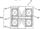
Bottom illustrates when saving locating piece unshakable in one's determination the making method of integrally formed frame in electromagnet portion.In the present embodiment shown in Figure 10~11, the iron core 20 that constitutes electromagnet portion 2 is loaded in locating piece 43a unshakable in one's determination or the locating piece 43b periphery unshakable in one's determination is assembled into electromagnet portion 2, locating piece 43a wherein unshakable in one's determination clips 1 magnet 41 and bonding 2 soft-magnetic bodies 42; Locating piece 43b unshakable in one's determination then clips 2 magnet, 41 bonding 3 soft-magnetic bodies 42.Thus, shown in Figure 10~11, the iron core 20 that coil has been installed is attracted by the magnetic field that aforementioned magnet 41 forms, to these iron core 20 location.Then this electromagnet portion 2 is disposed at the metal pattern with upper and lower mould recess.Again, inject resin, borrow at aforementioned electric magnet portion 2 outer surface moulded resins the frame 44 that the die casting resin-shaped that then is shaped becomes to this metal pattern inner chamber.Finish after the die casting, take off aforementioned locating piece 43a unshakable in one's determination, 43b.These locating piece 43a unshakable in one's determination, 43b can be used for continuous die casting and are shaped.
Following situation with regard to integrally formed frame 46 in 4 utmost points shown in Figure 12, the 4 coil type electromagnet portions 45 illustrates when saving locating piece unshakable in one's determination the making method of integrally formed frame in electromagnet portion.At first, as shown in figure 13, the iron core 20 that constitutes aforementioned electric magnet portion 45 is disposed at upper and lower mould recess central part has in the metal pattern that inserts with square core 47.Then to 45 energisings of aforementioned electric magnet portion.Thus, with aforementioned insertion with the attraction force of square core 47 and 20 electromagnetic forces unshakable in one's determination with 20 positioning and fixing unshakable in one's determination in aforementioned insertion with square core 47 in.Again, inject resin to the inner chamber of this metal pattern, by at aforementioned electric magnet portion 45 outer surface moulded resins, and the frame 46 that is shaped and forms by moulded resin.And, in the mode shown in Figure 10,11,12,13, can use the locating piece unshakable in one's determination of shape shown in Figure 3.Particularly, under the situation of Figure 12, Figure 13, as using Fig. 3 locating piece, it is easier to install to metal pattern.
Next other embodiments of electro magnetic vibration pump are described.Shown in Figure 14~16, the electro magnetic vibration pump of present embodiment is by electromagnet portion 2, vibrating member 4, vibrating reed 5, constitute with pump case 6.Wherein, electromagnet portion 2 is made of with pair of core 20 a pair of electromagnet 1 of aforementioned subtend configuration; Vibrating member 4 has aforementioned permanent magnet 3; Vibrating reed 5 is linked to aforementioned vibrating member 4 two ends; Pump case 6 is individually fixed in aforementioned electric magnet portion 2 both end sides.Make sound-proof wall 50 and frame 51 at aforementioned electric magnet portion 2 outer surfaces, wherein sound-proof wall 50 is located at the pump case 6 periphery positions that are fixed on aforementioned electric magnet portion 2 bi-side; Frame 51 is integrally formed with aforementioned 19 whiles of frame.In these sound-proof wall 50 inboard built-in aforementioned pump case 6; Clip sealing 52a at these pump case 6 sides and fixing side lid (valve housing cover) 52.This side lid 52 is made by metallic material, has high sound insulation (sound insulation).For ease of installing to the installation position, integrally formed installation leg on this side lid 52.
Under the situation of aforementioned sound-proof wall 50 inboard built-in pump case 6, be preferably in sound-proof wall 50 inboards of aforementioned pump case 6 and the side lid 52 inboard spaces 53 that form of being fixed in these sound-proof wall 50 end faces.Under the situation of not die casting sound-proof wall 50, must make by independent sound insulation housing etc. and form dual structure, and owing to form the pump case 6 in this space 53 and the dual structure of sound-proof wall 50, can relax the vibration of self-pumping portion by the air in this space 53, can be made into the small pump device that improves sound insulation.
In the present embodiment, when in aforementioned electric magnet portion 2, forming frame 51, preferably utilize the hole 38 of iron core 20 with metal pattern pin fixed iron core 20, moulded resin.And be preferably in this frame 51 bottoms integrally formed at least 1 air groove 54 simultaneously with baffler function.Having stored by this air groove 54 after the air that discharge nozzle 15 is discharged,, thereby can reduce exhaust sound from relief opening 55 exhausts.Because the filter that configuration is made by felt or polyester fibre etc. in aforementioned air 54, air by filter in the time can remove foreign material such as dust, so can discharge peace and quiet air.In addition, forming under the situation of a plurality of air grooves, wherein 1 can used as suction port filter insertion part; Other air groove can be used as the place of parts such as taking in relay, switch and uses.
Moreover, as shown in figure 17, the pump portion of being fixed in aforementioned electric magnet portion bi-side, be in the pump case 6 air suction inlet 60 with (or) be communicated with on the next door 62 of blank part 61 of suction chamber, also can built-inly be used to reduce the baffler that sucks sound with tail pipe (テ-Le パ イ プ) 63.Baffler is being installed with under the situation of tail pipe 63 on the aforementioned next door 62, preferably partial cut-out on this next door 62 is protected with cover 64 and be inserted into the tail pipe that is fixed on notch.
Bottom illustrates another embodiment of electro magnetic vibration pump.Shown in Figure 18~20, the electro magnetic vibration pump of present embodiment is the vibrating member that vibrating reed linked that replaces aforementioned vibrating reed type electro magnetic vibration pump, and makes the piston type electromagnetic oscillating column pump that uses the vibrating member 72 that forms piston 71.This piston type electromagnetic oscillating column pump, when in aforementioned electric magnet portion 73, forming frame 74, integrally formed cylinder portion 75 on this frame 74.On aforementioned vibrating member 72, disposing pair of permanent magnets 76, make this vibrating member 72 move left and right by the attraction force of electromagnet portion 73 and the restoring force of spring 77, fluid is discharged from exhaust port 80 after suction port 78,79 suctions of electromagnet portion 73 and vibrating member 72 formation.
Aforementioned vibrating member 72 is made in equidirectional mobile non-active type pump, but the present invention also is not limited thereto, and also can be: vibrating member be made of a pair of vibrating elements, becomes the active type pump that attracts repeatedly with bounce-back.
Till now, the solenoid pumps of magnet-type vibrating member has been described, but it only uses to not using magnet the electromagnet pump of soft-magnetic body vibrating members such as iron or ferro-alloy also applicable.As this electromagnet pump, utilize the attraction force of electromagnet and spring restoring force to make the reciprocal start of vibrating member.
Bottom illustrates an embodiment again of electro magnetic vibration pump.Shown in Figure 21~23, the electro magnetic vibration pump of present embodiment is made of the electromagnet portion 81 different with electro magnetic vibration pump shown in Figure 1, the vibrating member 4 with permanent magnet 3, the vibrating reed 5 that is linked to these vibrating member 4 two ends, the pump case 6 that is individually fixed in aforementioned electric magnet portion 81 both end sides.Clip sealing 7a at the side of this pump case 6 and fixed side lid (valve housing cover) 7.
Aforementioned electric magnet portion 81, electromagnet 1, a pair of minor diameter iron core 82 that is made of a pair of major diameter unshakable in one's determination 20 and the coiled wire-wound coil portion 21 of subtend configuration, the cruciform core locating piece 18 that is assembled into aforementioned a pair of major diameter unshakable in one's determination 20 and minor diameter 82 inside unshakable in one's determination are constituted, and frame 83 on its outer surface is shaped.The shape of aforementioned locating piece unshakable in one's determination 18 also is not limited thereto, and as shown in Figure 3, also can save the egative film between four bights of square hole portion 16.
In the present embodiment, owing in a single day store in recess 84, promptly suck suction chamber 8, so can reduce the suction sound by path 84a and 86a from the 87a of suction portion inhaled air.And from discharging after the air of discharging chamber 9 sucks recess 85 by path 86b and 84b, in case store in this recess 85, then promptly from discharge portion 88a discharge, so can reduce exhaust sound.The pump of present embodiment is compared with aforementioned pump with baffler function, owing to there is the recess with baffler function to be formed in the major diameter outside dimension unshakable in one's determination of electromagnet portion, so can make the pump miniaturization.
In the present embodiment, form recess 84,85,, suck sound or discharge sound so also can reduce owing in a pair of minor diameter iron core 82, at least one side's periphery position, form recess at the periphery position of aforementioned a pair of minor diameter 82 sides unshakable in one's determination.
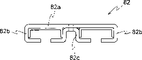
Major diameter iron core 20 shown in Figure 24 is the iron cores that become the E type with the same section of Fig. 2, it by yoke portion of foreign side 22, be disposed at the two-end part of this yoke portion of foreign side 22 side pole portion 23, dispose 23 in this side pole portion and become the center pole portion 24 of π shape to be constituted.And aforementioned minor diameter iron core 82, compare with aforementioned major diameter iron core 20, except that highly different formations identical, it by the 82a of yoke portion of foreign side, be disposed at the 82a of yoke portion of this foreign side two-end part the 82b of side pole portion, be disposed between the 82b of this side pole portion and become the 82c of center pole portion of π shape to be constituted.Yoke portion of aforementioned foreign side 22,82a and side pole portion 23,82b can be by block plates, integrally formed through pressure processing such as silicon steel plate.In the present embodiment, major diameter is unshakable in one's determination to be formed by the part assembling that plate pressure processing bending is formed with the minor diameter iron core, but the present invention also is not limited thereto, such as the major diameter iron core, shown in also can image pattern 26 like that, the silicon steel plate system stator iron core multilayer layer overlapping piece that processes from strand with the pre-configured silicon steel plate system stator multilayer layer overlapping piece unshakable in one's determination that processes in the 89b of side pole portion of the 89a of yoke portion of foreign side two-end part, with the 89c of center pole portion is made by welding etc. to be integral.In addition about the minor diameter iron core, also can be as shown in Figure 27, multilayer laminated being made of silicon steel plate system stator iron core that the pre-configured 90b of side pole portion in the 90a of yoke portion of foreign side two-end part and the 90c of the center pole portion one that is disposed at central authorities are processed.
The pump case 6 of present embodiment, shown in Figure 28~29, suction chamber 8 is formed at the above-below direction antimere with discharging chamber 9 by the next door 91 that roughly becomes X-shaped, forms blank part 92 at the left and right directions antimere by aforementioned next door 91 simultaneously.On the next door 91 that is separated out aforementioned suction chamber 8 and left and right sides blank part 92, formed and run through ditch 93.Run through the shape of ditch 93 as this, so long as can be communicated with the shape of blank part 92, not what special qualification can such as making otch ditch or hole.In addition about running through the quantity of ditch 93, the qualification that also has nothing special can suitably be selected.
In the present embodiment, link aforementioned suction chamber 8 and left and right sides blank part 92 owing to run through ditch 93 with 1 respectively, to sucking the suction sound of air, because blank part 92 can be brought into play the effect of sympathetic response shape noise elimination part, can be with the frequency f of following (1) formula to sucking the sound noise reduction.
In the formula, K is the blank part elastic constants that runs through the ditch per unit area; M is the quality that per unit area runs through ditch.Such as a pump sample, head pressure is 10 (KPa), frequency be the flow under 50Hz and the 60Hz situation be respectively 2.7 liters/minute with 26 liters/minute, as the pump designing tries that it has or not the noise level (A characteristic sound pressure level) that runs through under the ditch situation.Its result is as shown in table 1, from this table 1 as can be seen, has formed its noise level of pump case that runs through ditch and has hanged down 10 decibels approximately.
Table 1
| f (Hz) | Do not have and run through ditch (db) | The ditch of running through (db) is arranged |
| 50 | 52 | 40.5 |
| 60 | 54 | 42.0 |
Pump in the present embodiment, owing in pump case, formed blank part with baffler function, so can further reduce the suction sound.
Bottom illustrates the another embodiment of electro magnetic vibration pump.Such as, the shared electromagnet portion 81 that forms frame 83 on the outer surface, for reducing the die cast metal mold expense, the vibrating member that vibrating reed linked that replaces vibrating reed type electro magnetic vibration pump shown in Figure 21, and use has formed the vibrating member 102 of piston 101, fixing the pump case 104 that is provided with cylinder portion 103 in interior perimembranous simultaneously, fixing side lid 105 and clip sealing 105a at the pump portion side of this pump case 104.
In the present embodiment, aforementioned piston 101 separates making with piston shelf 108, also can integral production.
Shown in Figure 30~31, aforementioned pump case 104 is fixed on the frame 83 by the O shape ring 109 on the assembly department 35 that is fitted to frame 83 for sealed electrical magnet 2 inboards.On aforementioned frame 83, owing to formed recess 84,85 with baffler function, on aforementioned pump case 104, formed from the path 104a of suction chamber 110 openings of path 84a in pump case 104 of recess 84, and formed from the path 104b of discharge chamber 111 openings of path 85a in aforementioned pump case 104 of aforementioned recess 85.In the present embodiment, shown in Figure 31~34, suction chamber 110 is communicated with discharge chamber 111, the opening 112a that is formed by the next door 112 above-below direction position otch that form on interior all positions, simultaneously at these 112 left and right directions positions, next door, forms blank part 113.Thereby the pump portion of aforementioned pump case 104 is by suction chamber 110, discharge the pressing chamber 115 that chamber 111 and the ventilating hole 114 by aforementioned cylinder portion 103 be communicated with and constitute.
In aforementioned suction chamber 110 sides and discharge chamber 111 sides, shown in Figure 30 and Figure 35~36, have by the planar valve seat 116b that possesses ventilating hole 116a with such as the valve body 116 that the valve 116d of the central hole 116c that is fixed in this valve seat 116b constitutes, valve 116d direction is mutually oppositely is fitted to the ditch 117 that forms on pump case 104 inner wall parts respectively.In aforementioned pressing chamber 115, disposing the spring 118 of energizing by spring seat 119 to aforementioned vibrating member, to these spring 118 location, the lining seats of being fixed by the mounting screw 120 in the hole of inserting logical aforementioned side lid 105 121 carry out.
As aforementioned cylinder portion 103, not what special qualification, but, preferably use the easy metal of processing precision such as easy assurance concentricity and cylindricity for aforementioned piston 102 can smoothly be moved cylinder portion 103 in; In these metals, preferably use cheapness, self-lubricating property and lightweight aluminum or aluminum alloy pipe etc. are arranged.
The valve seat 116b of aforementioned valve body 116 be located at the cylinder portion 103 of pump case 104, but also integral production on this pump case 104; But under situation shown in the present embodiment,, on making, needn't process the vent that radially runs through at interior all positions, and can reduce pump case shaping cost owing to make respectively.
In the electro magnetic vibration pump of present embodiment,, formed recess with baffler function at the frame of vibrating reed type electro magnetic vibration pump shown in Figure 21; But in the present invention, be not limited thereto, frame is not had a baffler yet, such as applicable to vibrating reed type electro magnetic vibration pump shown in Figure 1 yet.Under the situation that is suitable for this pump, as shown in figure 33, on the next door 112 that is divided into aforementioned suction chamber 110 and blank part 113, form and run through ditch 130.Thus, because the outer gas that sucks is exhaust after in a single day storing in this blank part 113, can reduce exhaust sound.Perhaps, can further improve soundproof effect owing on pump, use aforementioned frame and the aforementioned pump case that runs through ditch of formation with baffler function.
According to above explanation, as according to the present invention, cost of production and improve the electro magnetic vibration pump of soundproof effect can be reduced.
Claims (23)
1. electro magnetic vibration pump, mutual magnetic action based on electromagnet portion that constitutes by one or more iron cores and magnetic, electric and magnetic oscillation by vibrating member with aforementioned magnetic, and the vibrating reed that is linked to aforementioned vibrating member is vibrated, it is characterized in that, by at aforementioned electric magnet portion outer surface moulded resin and the frame of shaping moulded resin;
Interior perimembranous in aforementioned electric magnet portion disposes the locating piece unshakable in one's determination of the electromagnet portion that is assembled into before aforementioned frame is shaped.
2. by the described electro magnetic vibration pump of claim 1, it is characterized in that, be assembled in the coiled wire-wound coil of the iron core in the aforementioned electric magnet portion, can insert aforementioned ground unshakable in one's determination die casting in advance and form.
3. by claim 1 or 2 described electro magnetic vibration pumps, it is characterized in that the integrally formed assembly department that is used to install vibrating reed on aforementioned frame.
4. by claim 1 or 2 described electro magnetic vibration pumps, it is characterized in that,, be formed with the pump case sound-proof wall that is fixed in aforementioned electric magnet portion bi-side at aforementioned frame.
5. by the described electro magnetic vibration pump of claim 3, it is characterized in that, be formed with at least 1 air groove at aforementioned frame.
6. by the described electro magnetic vibration pump of claim 4, it is characterized in that lid inboard, side inboard at aforementioned pump case sound-proof wall and that be fixed in this sound-proof wall end face is formed with the space.
7. by claim 1 or 2 described electro magnetic vibration pumps, it is characterized in that built-in baffler tail pipe in the pump case that is fixed in aforementioned electric magnet portion bi-side.
8. by claim 1 or 2 described electro magnetic vibration pumps, it is characterized in that, unshakable in one's determination and a pair of minor diameter iron core constitutes a plurality of iron cores of aforementioned electric magnet portion by highly different a pair of major diameters, in this a pair of minor diameter iron core, and the aforementioned frame formation recess at least one side's periphery position.
9. by claim 1 or 2 described electro magnetic vibration pumps, it is characterized in that,, form blank part by this next door at the left and right directions position simultaneously by the suction chamber of next door in the above-below direction position forms aforementioned pump case and discharge chamber; Be divided into to be formed with on the next door of aforementioned suction chamber and blank part and run through ditch.
10. by claim 1 or 2 described electro magnetic vibration pumps, it is characterized in that the side lid of fixing is made of metal on the side of the pump portion of the pump case that is fixed in aforementioned electric magnet portion bi-side, and cover in this side and to be formed with the installation leg.
11. by claim 1 or 2 described electro magnetic vibration pumps, it is characterized in that, replace with the vibrating member that is formed with piston and link the vibrating member that aforementioned vibrating reed is arranged; Replace the vibrating reed assembly department with the cylinder portion that forms one with electromagnet portion.
12., it is characterized in that replace with the vibrating member that is formed with piston and link the vibrating member that aforementioned vibrating reed is arranged, perimembranous is provided with cylinder portion in aforementioned pump case by claim 1 or 2 described electro magnetic vibration pumps.
13. by the described electro magnetic vibration pump of claim 12, it is characterized in that, in the suction chamber side of the pump portion of aforementioned pump case and discharge the chamber side, be equipped with the valve body that constitutes by valve seat with ventilating hole and valve respectively.
14. by the described electro magnetic vibration pump of claim 12, it is characterized in that,, form blank part by aforementioned next door at the left and right directions position simultaneously by the suction chamber of next door in the above-below direction position forms aforementioned pump case and discharge chamber; On the next door that is divided into aforementioned suction chamber and blank part, form and run through ditch.
15. the making method of an electro magnetic vibration pump, based on electromagnet portion that constitutes by one or more iron cores and the mutual magnetic action of magnetic, electric and magnetic oscillation by vibrating member with aforementioned magnetic, make the vibrating reed vibration that is linked to aforementioned vibrating member, it is characterized in that, it has: the iron core that will constitute aforementioned electric magnet portion inserts the operation of assembling electromagnet portion in the locating piece periphery unshakable in one's determination, the electromagnet portion that assembles is disposed at the operation that has the metal pattern that inserts usefulness Fang Xin at the recess central part, resin is injected this metal pattern inner chamber, operation at aforementioned electric magnet portion outer surface moulded resin.
16. the making method of an electro magnetic vibration pump, based on electromagnet portion that constitutes by one or more iron cores and the mutual magnetic action of magnetic, electric and magnetic oscillation by vibrating member with aforementioned magnetic, make the vibrating reed vibration that is linked to aforementioned vibrating member, it is characterized in that, it has: the iron core that will constitute aforementioned electric magnet portion is loaded on the operation that the locating piece periphery unshakable in one's determination that clips the bonding soft-magnetic body of magnet is assembled electromagnet portion, this electromagnet portion that assembles is disposed at the operation of metal pattern, resin is injected this metal pattern inner chamber, in the operation of aforementioned electric magnet portion outer surface moulded resin, and the die casting operation of taking off aforementioned locating piece unshakable in one's determination after finishing.
17. the making method of an electro magnetic vibration pump, mutual magnetic action based on electromagnet portion that constitutes by one or more iron cores and magnetic, electric and magnetic oscillation by vibrating member with aforementioned magnetic, make the vibrating reed vibration that is linked to aforementioned vibrating member, it is characterized in that, it has: after having assembled aforementioned electric magnet portion, the electromagnet portion that this assembling is intact is disposed at the recess central part has the operation of inserting with the metal pattern of Fang Xin, to the energising of aforementioned electromagnet portion, with the operation of positioning and fixing unshakable in one's determination, resin is injected this metal pattern inner chamber with electromagnetic attraction in aforementioned insertion usefulness Fang Xin, operation at aforementioned electric magnet portion outer surface moulded resin.
18. the making method by claim 15,16 or 17 described electro magnetic vibration pumps is characterized in that, when aforementioned electric magnet portion outer surface moulded resin, and the integrally formed assembly department that is used to install aforementioned vibrating reed.
19. by the making method of the described electro magnetic vibration pump of claim 18, it is characterized in that, integrally formed when being used to the assembly department of aforementioned vibrating reed is installed, the integrally formed pump case sound-proof wall that is fixed in aforementioned electric magnet portion bi-side.
20. by the making method of the described electro magnetic vibration pump of claim 19, it is characterized in that, integrally formed when being used to the assembly department of aforementioned vibrating reed is installed, integrally formed at least 1 air groove.
21. by the making method of the described electro magnetic vibration pump of claim 19, it is characterized in that, when the sound-proof wall of the integrally formed pump case that is fixed in aforementioned electric magnet portion bi-side, integrally formed at least 1 air groove.
22. the making method by the described electro magnetic vibration pump of claim 18 is characterized in that, a plurality of iron cores of aforementioned electric magnet portion are made of highly different a pair of major diameter iron core and a pair of minor diameter iron cores; In this a pair of minor diameter iron core, on the aforementioned frame at least 1 side's periphery position, form recess.
23. the making method by claim 15,16 or 17 described electro magnetic vibration pumps is characterized in that, replaces the vibrating member that links aforementioned vibrating reed with the vibrating member that is formed with piston, forms and integrally formed cylinder portion of electromagnet portion, replaces the vibrating reed assembly department.
Applications Claiming Priority (6)
| Application Number | Priority Date | Filing Date | Title |
|---|---|---|---|
| JP2000001006 | 2000-01-06 | ||
| JP1006/2000 | 2000-01-06 | ||
| JP227302/2000 | 2000-07-27 | ||
| JP2000227302 | 2000-07-27 | ||
| JP328537/2000 | 2000-10-27 | ||
| JP2000328537A JP3370653B2 (en) | 2000-01-06 | 2000-10-27 | Electromagnetic vibration pump and its manufacturing method |
Publications (2)
| Publication Number | Publication Date |
|---|---|
| CN1302960A CN1302960A (en) | 2001-07-11 |
| CN1271333C true CN1271333C (en) | 2006-08-23 |
Family
ID=27341988
Family Applications (1)
| Application Number | Title | Priority Date | Filing Date |
|---|---|---|---|
| CNB001380095A Expired - Fee Related CN1271333C (en) | 2000-01-06 | 2000-12-29 | Electro magnetic vibration pump and its manufacturing method |
Country Status (7)
| Country | Link |
|---|---|
| US (2) | US6533560B2 (en) |
| EP (1) | EP1114933A3 (en) |
| JP (1) | JP3370653B2 (en) |
| KR (1) | KR100793719B1 (en) |
| CN (1) | CN1271333C (en) |
| HK (1) | HK1039512A1 (en) |
| TW (1) | TW482874B (en) |
Cited By (1)
| Publication number | Priority date | Publication date | Assignee | Title |
|---|---|---|---|---|
| CN103790810A (en) * | 2012-10-31 | 2014-05-14 | 藤仓橡胶工业株式会社 | Electromagnetic diaphragm pump |
Families Citing this family (47)
| Publication number | Priority date | Publication date | Assignee | Title |
|---|---|---|---|---|
| JP4822198B2 (en) * | 2001-02-21 | 2011-11-24 | 並木精密宝石株式会社 | Actuator device for forced air supply and air battery for forced air supply |
| JP4365558B2 (en) | 2002-04-08 | 2009-11-18 | 株式会社テクノ高槻 | Electromagnetic vibration type diaphragm pump |
| US10363061B2 (en) | 2002-10-25 | 2019-07-30 | Hydrocision, Inc. | Nozzle assemblies for liquid jet surgical instruments and surgical instruments for employing the nozzle assemblies |
| GB0224986D0 (en) | 2002-10-28 | 2002-12-04 | Smith & Nephew | Apparatus |
| DE102004062300A1 (en) * | 2004-12-23 | 2006-07-13 | BSH Bosch und Siemens Hausgeräte GmbH | linear compressor |
| JP4603433B2 (en) * | 2005-07-11 | 2010-12-22 | 日東工器株式会社 | Electromagnetic reciprocating fluid device |
| JP4705433B2 (en) * | 2005-08-22 | 2011-06-22 | 東洋ゴム工業株式会社 | Active liquid-filled vibration isolator |
| US20070102233A1 (en) * | 2005-11-07 | 2007-05-10 | Eiko Electric Products Corp. | Air pumping device with silencing effect for aquarium |
| US20070217929A1 (en) * | 2006-03-17 | 2007-09-20 | Jackey Chiou | Diaphragm pumping device |
| EP1850005B1 (en) * | 2006-04-24 | 2009-10-07 | Yasunaga Air Pump, Inc. | Diaphragm pump |
| US20070258835A1 (en) * | 2006-05-05 | 2007-11-08 | Yasunaga Air Pump Inc. | Diaphragm pump |
| US7819642B2 (en) * | 2006-08-24 | 2010-10-26 | N.A.H. Zabar Ltd. | Reciprocatory fluid pump |
| JP5124219B2 (en) * | 2006-09-27 | 2013-01-23 | 日本電産テクノモータ株式会社 | Armature unit, method of manufacturing armature unit, motor and pump provided with armature unit |
| EP1905465B2 (en) | 2006-09-28 | 2013-11-27 | Smith & Nephew, Inc. | Portable wound therapy system |
| US8328538B2 (en) * | 2007-07-11 | 2012-12-11 | Gast Manufacturing, Inc., A Unit Of Idex Corporation | Balanced dual rocking piston pumps |
| GB0723855D0 (en) | 2007-12-06 | 2008-01-16 | Smith & Nephew | Apparatus and method for wound volume measurement |
| NO334755B1 (en) * | 2008-12-08 | 2014-05-19 | Gjerdrum As Ing | Pump or compressor drive device |
| US20100305402A1 (en) * | 2009-05-29 | 2010-12-02 | Magnetecs,Inc. | Method and apparatus for magnetic waveguide forming a shaped field employing a magnetic aperture for guiding and controlling a medical device |
| US20110112396A1 (en) | 2009-11-09 | 2011-05-12 | Magnetecs, Inc. | System and method for targeting catheter electrodes |
| DE102009047743A1 (en) * | 2009-12-09 | 2011-06-16 | BSH Bosch und Siemens Hausgeräte GmbH | Compressor with a carrying frame |
| GB201011173D0 (en) | 2010-07-02 | 2010-08-18 | Smith & Nephew | Provision of wound filler |
| US20120020818A1 (en) * | 2010-07-20 | 2012-01-26 | Peter Chen | Air compressor structure for paint spraying |
| CN102338071A (en) * | 2010-07-21 | 2012-02-01 | 三敏电机股份有限公司 | Improved structure applied to spray-painted air compressor |
| GB201015656D0 (en) | 2010-09-20 | 2010-10-27 | Smith & Nephew | Pressure control apparatus |
| GB201020005D0 (en) | 2010-11-25 | 2011-01-12 | Smith & Nephew | Composition 1-1 |
| WO2012069794A1 (en) | 2010-11-25 | 2012-05-31 | Smith & Nephew Plc | Composition i-ii and products and uses thereof |
| JP5849415B2 (en) * | 2011-03-22 | 2016-01-27 | シンフォニアテクノロジー株式会社 | Linear drive device and manufacturing method thereof |
| JP5389081B2 (en) * | 2011-03-22 | 2014-01-15 | 株式会社テクノ高槻 | Electromagnetic vibration type diaphragm pump |
| US8974200B2 (en) * | 2011-07-08 | 2015-03-10 | International Business Machines Corporation | Device for creating fluid flow |
| US9084845B2 (en) | 2011-11-02 | 2015-07-21 | Smith & Nephew Plc | Reduced pressure therapy apparatuses and methods of using same |
| US20150159066A1 (en) | 2011-11-25 | 2015-06-11 | Smith & Nephew Plc | Composition, apparatus, kit and method and uses thereof |
| US9427505B2 (en) | 2012-05-15 | 2016-08-30 | Smith & Nephew Plc | Negative pressure wound therapy apparatus |
| JP6013791B2 (en) * | 2012-06-12 | 2016-10-25 | 藤倉ゴム工業株式会社 | Electromagnetic diaphragm pump |
| CN102767508A (en) * | 2012-07-06 | 2012-11-07 | 上海应用技术学院 | Diaphragm type electromagnetic air pump |
| CN103089593B (en) * | 2012-11-27 | 2015-10-07 | 刘春祥 | axial magnetic diaphragm pump |
| US20160120706A1 (en) | 2013-03-15 | 2016-05-05 | Smith & Nephew Plc | Wound dressing sealant and use thereof |
| CN103184995B (en) * | 2013-04-24 | 2015-08-19 | 赵德连 | Magnetoelectric kinetic energy compressor |
| US20150147202A1 (en) * | 2013-11-27 | 2015-05-28 | Gardner Denver Thomas, Inc. | Pump having interchangeable heads |
| JP6353771B2 (en) * | 2014-11-25 | 2018-07-04 | 株式会社日立製作所 | Linear motor and compressor equipped with linear motor |
| AU2015370586B2 (en) | 2014-12-22 | 2020-07-16 | Smith & Nephew Plc | Negative pressure wound therapy apparatus and methods |
| KR20160127927A (en) * | 2015-04-28 | 2016-11-07 | 임주생 | Electromagnetic air compressor |
| CN104776007B (en) * | 2015-05-06 | 2017-09-29 | 王守福 | Opposed type permanent-magnetism electromagnetic air pump |
| US11002270B2 (en) * | 2016-04-18 | 2021-05-11 | Ingersoll-Rand Industrial U.S., Inc. | Cooling methods for electrically operated diaphragm pumps |
| CN106567821B (en) * | 2016-11-07 | 2018-10-30 | 骆金山 | Electromagnetic push-pull diaphragm pump |
| CN110005849A (en) * | 2019-04-12 | 2019-07-12 | 山东朗高计量泵科技有限公司 | For driving the electromagnetic assembly of double pump head metering pump |
| US12085066B2 (en) * | 2021-02-23 | 2024-09-10 | Ventriflo, Inc. | Pulsatile fluid pump system |
| CN113007078A (en) * | 2021-03-31 | 2021-06-22 | 中国长江电力股份有限公司 | Multifunctional fluid pumping device |
Family Cites Families (20)
| Publication number | Priority date | Publication date | Assignee | Title |
|---|---|---|---|---|
| FR1535489A (en) * | 1967-04-21 | 1968-08-09 | Improvements to DC motors without a commutator and some devices that use them | |
| JPS53140603A (en) * | 1977-05-16 | 1978-12-07 | Enomoto Maikuroponpu Seisakush | Reciprocating type electromagnetic pump |
| IT1130947B (en) * | 1980-03-10 | 1986-06-18 | De Dionigi Manlio | IMPROVEMENTS TO ALTERNATIVE ELECTROMAGNETIC PUMPS IN PARTICULAR FOR NON-VISCOUS FLUIDS |
| JPS58148646A (en) * | 1982-02-24 | 1983-09-03 | Matsushita Electric Ind Co Ltd | Manufacture of resin molded motor |
| US4877378A (en) * | 1985-12-11 | 1989-10-31 | Saggers Michael J | Vibratory diaphragm pumps |
| US4775301A (en) * | 1986-06-27 | 1988-10-04 | Cartwright Garry E | Oscillating electromagnetic pump with one-way diaphragm valves |
| JPH0694867B2 (en) * | 1986-11-26 | 1994-11-24 | 松下電工株式会社 | Electromagnetic air pump |
| US5013223A (en) * | 1987-08-20 | 1991-05-07 | Takatsuki Electric Mfg. Co., Ltd. | Diaphragm-type air pump |
| JPH0744766Y2 (en) * | 1988-11-10 | 1995-10-11 | 日東工器株式会社 | Air compressor |
| JP2531877Y2 (en) * | 1988-12-15 | 1997-04-09 | 日東工器株式会社 | Electromagnetic diaphragm pump |
| US5189782A (en) * | 1990-12-20 | 1993-03-02 | Ford Motor Company | Method of making integrally formed and tuned fuel rail/injectors |
| US5490319A (en) * | 1992-01-29 | 1996-02-13 | Ebara Corporation | Thermotropic liquid crystal polymer composition and insulator |
| JP3048490B2 (en) * | 1993-10-29 | 2000-06-05 | 株式会社テクノ高槻 | Diaphragm pump |
| US5423117A (en) * | 1994-01-11 | 1995-06-13 | Smc Corporation | Method for fabricating solenoid device for electromagnetic valves |
| JPH07259742A (en) * | 1994-03-25 | 1995-10-09 | Mitsubishi Chem Corp | Diaphragm type air pump |
| DE4439823C1 (en) * | 1994-11-08 | 1996-01-18 | Richter Siegfried Dipl Ing Fh | Mfg. process for leaf vibration springs for electric diaphragm pumps |
| AU693275B2 (en) * | 1994-11-14 | 1998-06-25 | Anton Steiger | Device for guiding and centring a machine component |
| US5567131A (en) * | 1995-04-20 | 1996-10-22 | Gorman-Rupp Industries | Spring biased check valve for an electromagnetically driven oscillating pump |
| JP2000504919A (en) * | 1996-02-12 | 2000-04-18 | チバ スペシャリティ ケミカルズ ホールディング インコーポレイテッド | Manufacturing method of magnetic core made by laminating thin plates and electromagnetic unit manufactured from this |
| US6012910A (en) * | 1997-07-28 | 2000-01-11 | The Gorman-Rupp Company | Electromagnetic oscillating pump with self-aligning springs |
-
2000
- 2000-10-27 JP JP2000328537A patent/JP3370653B2/en not_active Expired - Fee Related
- 2000-12-19 TW TW089127259A patent/TW482874B/en not_active IP Right Cessation
- 2000-12-27 KR KR1020000083081A patent/KR100793719B1/en not_active IP Right Cessation
- 2000-12-29 CN CNB001380095A patent/CN1271333C/en not_active Expired - Fee Related
-
2001
- 2001-01-02 US US09/753,156 patent/US6533560B2/en not_active Expired - Fee Related
- 2001-01-05 EP EP01300070A patent/EP1114933A3/en not_active Withdrawn
- 2001-11-12 HK HK01107932A patent/HK1039512A1/en not_active IP Right Cessation
-
2002
- 2002-12-13 US US10/318,875 patent/US6977056B2/en not_active Expired - Fee Related
Cited By (2)
| Publication number | Priority date | Publication date | Assignee | Title |
|---|---|---|---|---|
| CN103790810A (en) * | 2012-10-31 | 2014-05-14 | 藤仓橡胶工业株式会社 | Electromagnetic diaphragm pump |
| CN103790810B (en) * | 2012-10-31 | 2016-12-07 | 藤仓橡胶工业株式会社 | Eletromagnetic diaphragm pump |
Also Published As
| Publication number | Publication date |
|---|---|
| HK1039512A1 (en) | 2002-04-26 |
| US20030082056A1 (en) | 2003-05-01 |
| US20010008608A1 (en) | 2001-07-19 |
| US6977056B2 (en) | 2005-12-20 |
| JP3370653B2 (en) | 2003-01-27 |
| KR20010070364A (en) | 2001-07-25 |
| EP1114933A3 (en) | 2002-12-18 |
| JP2002106472A (en) | 2002-04-10 |
| EP1114933A2 (en) | 2001-07-11 |
| TW482874B (en) | 2002-04-11 |
| US6533560B2 (en) | 2003-03-18 |
| KR100793719B1 (en) | 2008-01-10 |
| CN1302960A (en) | 2001-07-11 |
Similar Documents
| Publication | Publication Date | Title |
|---|---|---|
| CN1271333C (en) | Electro magnetic vibration pump and its manufacturing method | |
| CN1040606C (en) | Electracoustic transducer and method of fabricating the same | |
| KR100900034B1 (en) | Electromagnetic vibrating type diaphragm pump | |
| CN1038179C (en) | Electroacoustic transducer | |
| CN1242721A (en) | Electric-mechanical-acoustic transducer and method for mfg. same | |
| JP2001073942A (en) | Linear compressor | |
| CN1121300A (en) | Loudspeaker with magnetic circuit | |
| JPWO2021149236A5 (en) | ||
| CN1140702C (en) | Linear compressor piston operation assembly and its manufacturing method | |
| CN1151702C (en) | Electromagnetic voice converter | |
| JP2002371968A (en) | Electromagnetic vibrating pump and pump unit | |
| JP2000299971A (en) | Electromagnetic drive mechanism and electromagnetic vibrating pump using the same | |
| WO2022142464A1 (en) | Stator, motor, compressor and refrigeration device | |
| KR101200586B1 (en) | Linear motor for linear compressor | |
| JP3485551B2 (en) | Electromagnetic vibration type pump | |
| CN1194171C (en) | Electromagnetic compressor and method of manufacturing the compressor | |
| CN101205897B (en) | Draining valve assembly of linear compressor | |
| CN220965141U (en) | Sound generating device and electronic equipment | |
| JP2807746B2 (en) | Vibration pump | |
| CN1244089C (en) | Electric sound transducer | |
| JP3500365B2 (en) | Electromagnet part | |
| CN1193885A (en) | Electromagnetic acoustic transducer | |
| CN115580796A (en) | Multifunctional sound production device | |
| JP2568595Y2 (en) | Permanent magnet rotor | |
| JPH0759947B2 (en) | Cylindrical electromagnetic vibration pump |
Legal Events
| Date | Code | Title | Description |
|---|---|---|---|
| C06 | Publication | ||
| PB01 | Publication | ||
| C10 | Entry into substantive examination | ||
| SE01 | Entry into force of request for substantive examination | ||
| C14 | Grant of patent or utility model | ||
| GR01 | Patent grant | ||
| C17 | Cessation of patent right | ||
| CF01 | Termination of patent right due to non-payment of annual fee |
Granted publication date: 20060823 Termination date: 20121229 |