CN1265896C - Vibrating element and vibrating wave driving device - Google Patents
Vibrating element and vibrating wave driving device Download PDFInfo
- Publication number
- CN1265896C CN1265896C CNB021024553A CN02102455A CN1265896C CN 1265896 C CN1265896 C CN 1265896C CN B021024553 A CNB021024553 A CN B021024553A CN 02102455 A CN02102455 A CN 02102455A CN 1265896 C CN1265896 C CN 1265896C
- Authority
- CN
- China
- Prior art keywords
- elastic component
- vibrating elements
- flange
- vibration
- driving device
- Prior art date
- Legal status (The legal status is an assumption and is not a legal conclusion. Google has not performed a legal analysis and makes no representation as to the accuracy of the status listed.)
- Expired - Fee Related
Links
- 238000006243 chemical reaction Methods 0.000 claims abstract description 15
- 238000006073 displacement reaction Methods 0.000 claims description 10
- 238000005452 bending Methods 0.000 abstract description 6
- 230000014509 gene expression Effects 0.000 description 12
- 230000010355 oscillation Effects 0.000 description 10
- 230000007246 mechanism Effects 0.000 description 8
- 230000008878 coupling Effects 0.000 description 4
- 238000010168 coupling process Methods 0.000 description 4
- 238000005859 coupling reaction Methods 0.000 description 4
- 238000013016 damping Methods 0.000 description 4
- 230000014759 maintenance of location Effects 0.000 description 4
- PNEYBMLMFCGWSK-UHFFFAOYSA-N Alumina Chemical compound [O-2].[O-2].[O-2].[Al+3].[Al+3] PNEYBMLMFCGWSK-UHFFFAOYSA-N 0.000 description 3
- 230000004323 axial length Effects 0.000 description 3
- 238000005516 engineering process Methods 0.000 description 3
- CNQCVBJFEGMYDW-UHFFFAOYSA-N lawrencium atom Chemical compound [Lr] CNQCVBJFEGMYDW-UHFFFAOYSA-N 0.000 description 3
- 239000000463 material Substances 0.000 description 3
- 230000013011 mating Effects 0.000 description 3
- 230000009467 reduction Effects 0.000 description 3
- 238000009434 installation Methods 0.000 description 2
- 239000002184 metal Substances 0.000 description 2
- 229910052751 metal Inorganic materials 0.000 description 2
- 238000004904 shortening Methods 0.000 description 2
- 229910001369 Brass Inorganic materials 0.000 description 1
- -1 and for example Inorganic materials 0.000 description 1
- 239000010951 brass Substances 0.000 description 1
- 229910010293 ceramic material Inorganic materials 0.000 description 1
- 230000008859 change Effects 0.000 description 1
- 125000004122 cyclic group Chemical group 0.000 description 1
- 230000003292 diminished effect Effects 0.000 description 1
- 230000005284 excitation Effects 0.000 description 1
- 230000006872 improvement Effects 0.000 description 1
- 239000007769 metal material Substances 0.000 description 1
- 238000012856 packing Methods 0.000 description 1
- 230000000644 propagated effect Effects 0.000 description 1
Images


Classifications
-
- H—ELECTRICITY
- H02—GENERATION; CONVERSION OR DISTRIBUTION OF ELECTRIC POWER
- H02N—ELECTRIC MACHINES NOT OTHERWISE PROVIDED FOR
- H02N2/00—Electric machines in general using piezoelectric effect, electrostriction or magnetostriction
-
- H—ELECTRICITY
- H02—GENERATION; CONVERSION OR DISTRIBUTION OF ELECTRIC POWER
- H02N—ELECTRIC MACHINES NOT OTHERWISE PROVIDED FOR
- H02N2/00—Electric machines in general using piezoelectric effect, electrostriction or magnetostriction
- H02N2/0005—Electric machines in general using piezoelectric effect, electrostriction or magnetostriction producing non-specific motion; Details common to machines covered by H02N2/02 - H02N2/16
- H02N2/001—Driving devices, e.g. vibrators
- H02N2/0015—Driving devices, e.g. vibrators using only bending modes
-
- H—ELECTRICITY
- H02—GENERATION; CONVERSION OR DISTRIBUTION OF ELECTRIC POWER
- H02N—ELECTRIC MACHINES NOT OTHERWISE PROVIDED FOR
- H02N2/00—Electric machines in general using piezoelectric effect, electrostriction or magnetostriction
- H02N2/10—Electric machines in general using piezoelectric effect, electrostriction or magnetostriction producing rotary motion, e.g. rotary motors
- H02N2/106—Langevin motors
Landscapes
- General Electrical Machinery Utilizing Piezoelectricity, Electrostriction Or Magnetostriction (AREA)
Abstract
This invention relates to a vibration wave driving apparatus including an electro-mechanical energy conversion element that is sandwiched and fixed between elastic members, in which a flange-shaped elastic member is provided between the electro-mechanical energy conversion element and one of the elastic members. When a driving vibration is applied to the electro-mechanical energy conversion element, a vibration element excites bending vibrations and those bending vibrations allow out-of-plane bending vibrations to be excited in the flange-shaped elastic member. Since a rotor is brought into contact with the third elastic member sandwiched between the elastic member and the electro-mechanical energy conversion element, the size of the vibration wave driving apparatus can be reduced. In addition, since a travelling wave produced by the bending vibration of the vibration element and a travelling wave produced by the out-of-plane bending vibration of the third elastic member are generated at the frictional surface of the vibration element, the output of the vibration wave driving apparatus can be improved.
Description
Invention field
The present invention relates to a kind of vibration wave driving device, more specifically, relate to a kind of structure that is used in the vibrating elements in a kind of bar shaped vibration wave driving device.
Prior art
A kind of bar shaped vibration wave driving device comprises: a vibrating elements and a piezoelectric element, and the elastic component that this vibrating elements is made by metal or similar material constitutes, and as a foundation structure, this piezoelectric element is as an electric energy-mechanical energy conversion element.By apply a kind of alternating voltage to piezoelectric element, this bar shaped vibration wave driving device produces a kind of driving vibration, for example, a kind of capable ripple or similar ripple, wherein this alternating voltage has different phase places as a kind of AC signal.
A contact contacts with a drive part pressure of elastic component by a pressing mechanism, this contact is activated the friction-driven of vibration simultaneously, thereby make vibrating elements and contact move relative to each other, wherein this driving vibration is the vibration that produces in the drive part of elastic component.
With the example of a vibration wave motor as a vibration wave driving device, in this vibration wave driving device, a vibrating elements is used as a stator herein, and a contact is used as a rotor.
The example of the vibrating elements of vibration wave motor comprises: those have a kind of like this structural vibrations element, and in this structure, an annular piezoelectric element dish is installed on the surface of an annular or dish type elastic component; Have such one type vibrating elements with those, in the type, rotatablely moving of rotor is output by an output shaft, and perhaps, in the type, rotatablely moving of rotor directly exported.
A kind of vibration wave motor so has been applied in the product, and these products are used to drive the camera lens of a camera, or the like.Cyclic type and the vibration wave motor strip type are arranged now.
Figure 10 A is the topology view of a bar shaped vibrating elements of a bar shaped vibration wave motor, and this bar shaped vibration wave motor is used to drive the camera lens of a camera.Figure 10 B has represented the mode of oscillation (represent axis direction with the z-axle, represent radial direction with the r-axle) in the axis portion of this bar shaped vibrating elements.
One first elastic component of Reference numeral 101 expressions; One second elastic component of Reference numeral 102 expressions; Piezoelectric element of Reference numeral 103 expressions.Axle spare of Reference numeral 106 expressions, this part passes first elastic component 101, piezoelectric element 103 and second elastic component 102.The end that axle part 106 is positioned at rotor 110 sides is fixed on the counterpart 109, and this counterpart 109 will be installed on the product, and the other end of axle part 106 is fixed on the nut 115.A threaded portion is formed on the other end of a part 106.Along with the change of nut 115 is tight, it is clamped and be fixed between this flange portion and this nut 115 to be placed on first elastic component 101 between a flange portion and the nut 115, piezoelectric element 103 and second elastic component 102, and wherein this flange portion is the processed part 106 that is used for fixing.The aforesaid rotor of Reference numeral 110 expressions, friction member of Reference numeral 107 expressions, this friction member is fixed on first elastic component 101, and will contact with this rotor.
When a driving signal was applied on the piezoelectric element 103, the represented flexural vibrations (in the principal curvature vibration of Figure 10 B) of Figure 10 B just were excited in this bar shaped vibrating elements, so this bar shaped vibrating elements is done oscillating motion about the z-axle substantially.Correspondingly, friction member 107 is around the z-axis rotation.
The vibrating elements that appears to a kind of like this bar shaped vibration wave driving device is reduced along its radial direction dimensionally, but along the direction of its propelling, promptly the length direction of its axis still leaves the leeway that dwindles dimensionally.
Yet when this vibrating elements is shortened simply, can cause following problem: resonant frequency increases; Vibration displacement is reduced, and will cause the reduction of friction-driven efficient, because the increase of the increase of the price of the components of drive circuit that causes of high frequency or the loss of this element internal.In addition, when the simple attenuation of this vibrating elements quilt, during with the reduction resonant frequency, the diameter of a piezoelectric element and a friction surface also are reduced simultaneously, thereby reduce the generation power and the friction torque of this piezoelectric element.Therefore, can expect that the output of this motor is also diminished.
As a kind of technology that is used to address the above problem and shorten the axial length of a bar shaped vibration wave driving device, a kind of like this technology is disclosed, specifically as shown in figure 11 in Japanese patent application No.2001-145376.
A vibrating device in the document and the something in common of a traditional product be, piezoelectric element 203 is clamped and be fixed between one first elastic component 201 and one second elastic component 202.Yet the difference of this device and traditional product is that first elastic component 201 with a friction surface is divided into an inner-diameter portion whose and an outer radius portion, and these two parts are connected one to the other to together by a thin coupling part 210.
According to this structure, even the axis of this bar shaped elastic component is shortened, because first elastic component has enough big quality, so also can access a low resonant frequency.
Yet, according to this technology, when coupling part 210 by attenuation so that resonant frequency is lowered, thereby when its rigidity was destroyed, the displacement that results from the piezoelectric element was absorbed by a slinky spring of this coupling part 210.Therefore, be difficult to driving force is delivered on the rotor effectively.Therefore, as if also there is further room for improvement.
Summary of the invention
One aspect of the present invention provides a kind of vibration wave driving device, this vibration wave driving device comprise vibratory elements and rotor, this vibrating elements has the elastic component that electric energy-the mechanical energy conversion element is fixed thereon, this rotor contacts with the friction surface of this vibrating elements, and drive rotor by the row ripple, this row ripple is to be applied on electric energy-mechanical energy conversion element and to result from the lip-deep of this vibrating elements by driving signal; Wherein: described vibrating elements comprises first elastic component, second elastic component and has the described elastic component of conduct the 3rd elastic component of described friction surface; Described the 3rd elastic component and described electric energy-mechanical energy conversion element are placed between described first elastic component and described second elastic component; Described rotor be positioned at described first elastic component near; The first row ripple and the second row ripple form described capable ripple by superposeing, so that produce circular or oval motion at the friction surface of described the 3rd elastic component, wherein, the described first row ripple is formed by flexural vibrations, these flexural vibrations with the parallel plane direction displacement that comprises as the axis of the center of rotation of described capable ripple, the described second row ripple is formed by the hyperplane flexural vibrations that result from described the 3rd elastic component.Because a rotor contacts with the 3rd elastic component that is clipped between elastic component and electric energy-mechanical energy conversion element, so the size of this vibration wave driving device can be reduced.Because a kind of ripple of going that a kind of hyperplane flexural vibrations of going ripple and the 3rd elastic component that the flexural vibrations of this vibrating elements produce produce all produces on the friction surface of this vibrating elements, so the output of this vibration wave driving device can be enhanced.
To brief description of drawings
Fig. 1 is the cutaway view of a vibrating elements, and this vibrating elements has been represented one first embodiment of the present invention.
Fig. 2 A and 2B are respectively mode of oscillation curve maps, and these curve maps are used to explain of the present invention.
Fig. 3 A and 3B are respectively curve maps, these graphical representation a mode of oscillation of a vibrating elements, this vibrating elements has represented that one of the present invention drives principle.
Fig. 4 A and 4B are respectively curve maps, these graphical representation another mode of oscillation of a vibrating elements, this vibrating elements has represented that one of the present invention drives principle.
Fig. 5 is the cutaway view of a vibrating elements, and this vibrating elements has been represented one second embodiment of the present invention.
Fig. 6 is the cutaway view of a vibrating elements, and this vibrating elements has been represented one the 3rd embodiment of the present invention.
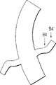
Fig. 7 A and 7B are respectively a perspective view and cutaway views of a vibrating elements, and this vibrating elements has been represented one the 4th embodiment of the present invention.
Fig. 8 is the cutaway view of a vibrating elements, and this vibrating elements has been represented one the 5th embodiment of the present invention.
Fig. 9 is the topology view of a vibration wave driving device, and this vibration wave driving device has been represented one the 6th embodiment of the present invention.
Figure 10 A is the cutaway view of a conventional strip vibration wave driving device; Figure 10 B is a curve map, this graphical representation the mode of oscillation of vibrating elements of this bar shaped vibration wave driving device;
Figure 11 is the cutaway view of a traditional vibration wave driving device, and this vibration wave driving device has the axial length of a shortening.
Detailed description of the preferred embodiment
First embodiment
Because be installed in mass member on the end of a slinky spring (coupling part 210) as a friction surface, so cause the problem of invention disclosed among the Japanese patent application No.2001-145376.Therefore, can imagine and just can address this problem separated from one another by a functor that is used to reduce resonant frequency and a functor that is used for output drive strength.
Fig. 1 has represented one first embodiment of the present invention.One first elastic component of Reference numeral 1 expression, this elastic component is processed to a cylindrical shape, and by the little material of a kind of vibration damping loss, for example brass is made.Reference numeral 5 an expression flange-shape (dish type) elastic components, this flange-shape elastic component is by ceramic material, and for example, aluminium oxide is made.
In Fig. 1, be arranged on the surface of flange-shape elastic component 5 with the contacted rubbing surface of rotor, it is relative with piezoelectric element 3 contacted surfaces with excircle.This friction surface is formed on the outer circumferential area of flange-shape elastic component 5.The thickness of flange-shape elastic component 5 that is positioned at the friction surface zone is thicklyer slightly processed, and as the core of this flange-shape elastic component 5, in this central part office, this flange-shape elastic component 5 is supported by first elastic component 1 and be fixing.Be processed to groove by the zone between the near zone that makes this core and excircle, this is the area that grinds accepting in order to reduce, thereby shortens the time of handling.In this case, as as can be seen clearly from figure 1, the near zone of the excircle of flange-shape elastic component 5 extends outwardly beyond the excircle part of first elastic component 1 and the excircle part of piezoelectric element 3, and this first elastic component 1 is adjacent with this flange-shape elastic component 5 with this piezoelectric element 3.
One group of piezoelectric element of Reference numeral 3 expressions.As this piezoelectric element group, a piezoelectric element in the middle of a kind of folded formula piezoelectric element is placed, should constitute by several elements or several sheet type piezoelectric elements by piling up by folded formula piezoelectric element with heat hardening, wherein these several elements each thereon and following both sides all have electrode, each sheet type piezoelectric element also all has electrode with following both sides thereon, by piling up and these elements of heat hardening, make it to become one.
One second elastic component of Reference numeral 2 expressions, this second elastic component is made by a kind of material with low vibration damping loss characteristic, and is identical with the situation of first elastic component 1.
This is combined as the axle spare 6 of a retention mechanism by one for first elastic component 1, second elastic component 2, flange-shape elastic component 5 and piezoelectric element 3, to form one.Axle part 6 is processed with a threaded portion at the one end, this part 6 is inserted by the end from first elastic component 1 simultaneously, thereby passed piezoelectric element 3, this threaded portion is tightened in the female thread portion of a processing in the axis centre part of second elastic component 2 then.Flange-shape elastic component 5 and piezoelectric element 3 are placed between first elastic component 1 and second elastic component 2, in this case, be used for fixing the flange portion of a part 6 and the threaded portion on the end of processing at axle spare 6 by one at processed on the mid portion of axle spare 6, above-mentioned can both be clamped and fixing.Another end parts of axle part 6 is fixed on the counterpart 9, and this part 6 supports whole bar shaped vibrating elements.In the present embodiment, this vibrating elements is processed like this, and promptly except that flange-shape elastic component 5, all parts of this vibrating elements all have identical external diameter.
Drive signal by when a unshowned drive circuit is applied on the piezoelectric element 3 when one, a principal curvature vibration just is excited in this bar shaped vibrating elements that constitutes like this, in addition, the flexural vibrations of a main circumference hyperplane are excited in flange-shape elastic component 5, and these main circumference hyperplane flexural vibrations do not comprise any circle that will become the node of this vibration.
At that time, the position of the antinode of principal curvature vibration just is disposed on the position of the center surface that breaks away from flange-shape elastic component 5, and wherein this principal curvature vibration is moved along a radial direction, and is excited by above-mentioned bar shaped vibrating elements.Here one used of " radial direction " expression is included in a direction in the plane, this plane and the straight line quadrature that passes the center separately of first elastic component 1, flange-shape elastic component 5, piezoelectric element 3 and second elastic component 2.
As the flexural vibrations that in this bar shaped vibrating elements, generate, also can use a kind of high frequent vibration, for example, second order or the vibration of three rank, and can not cause any problem.Yet, under so a kind of situation, just be necessary flange-shape elastic component 5 is placed on the position of anti-node location of an a kind of like this vibration of disengaging.
Next, explanation hereinafter will be directly at driving principle of the present invention.
People know, when hyperplane flexural vibrations are excited in a dish and are allowed to propagate, will produce a kind of circular motion or elliptic motion on the surface of this dish.
In this connection, will be in Japanese patent application No.4-91668 disclosed a kind of device is as an example that has with the device of the similar shape of the shape of the bar shaped vibrating elements of present embodiment, and this device has the mode of oscillation shown in a kind of Fig. 2 A.Yet, under a kind of like this situation of structure, promptly in this structure, the center surface 8 of flange-shape elastic component is consistent with the cardinal principle center A of the antinode of the flexural vibrations of a bar shaped vibrating elements, the situation of the mode as shown in Fig. 2 A, this flange-shape elastic component is only radially done a kind of translational motion by a principal curvature vibration.
Otherwise, when the center surface 8 of flange-shape elastic component is in the position of center A of antinode of flexural vibrations that depart from this bar shaped vibrating elements, except translational motion radially, this flange-shape elastic component can also excite a kind of rotatablely moving around an axis perpendicular to this bar shaped vibrating elements axis (this axis is orthogonal to x-axle and the z-axle among Fig. 2 B), and wherein this mode that departs from the flexural vibrations of this bar shaped vibrating elements is represented in Fig. 2 B of expression present embodiment.Therefore, when the displacement that comprises the component on the direction of propulsion with when following the inertia force of this displacement to act on the near zone of excircle of flange-shape elastic component simultaneously, this flange-shape elastic component also can produce a kind of displacement component that comprises on the direction of propulsion, i.e. hyperplane flexural deformation, vibration.In addition, because the flexural vibrations that are excited in this bar shaped vibrating elements are rotated around axis, the inertia force that acts on this flange-shape elastic component is used to excite the form of the power of these flexural vibrations to propagate on the circumference of this flange-shape elastic component with one, correspondingly, the hyperplane flexural vibrations of this flange-shape elastic component are also propagated.
When hyperplane flexural vibrations of advancing were produced on a flange-shape object, elliptic motion was just produced on this flange-shape elastic component surface, and this is a well-known phenomenon.Therefore, when the direction of rotation of the direction of rotation that makes this elliptic motion when the rotation of the flexural vibrations by this bar shaped vibrating elements and circular motion that results from this flange-shape elastic component or elliptic motion is consistent, a rotating speed that is subjected to the rotor of this flange-shape elastic member presses just is increased, thereby this motor properties is enhanced.
When this flange-shape elastic component be installed in the flexural vibrations that act on this flange-shape elastic component antinode the center below the time, rotor and the contacted position of this vibrating elements just are lowered, thus the size of whole vibration wave driving device can be reduced.
Fig. 3 A and 3B have represented a kind of mode of oscillation respectively, in this mode of oscillation, the flexural vibrations of the flexural vibrations of this bar shaped vibrating elements and this flange-shape elastic component are coupled each other, and wherein the flexural vibrations of this flange-shape elastic component do not comprise any circle that will become the node of this vibration.Fig. 4 A and 4B have represented a kind of mode of oscillation respectively, in this mode of oscillation, the flexural vibrations of the flexural vibrations of this bar shaped vibrating elements and this flange-shape elastic component are coupled each other, and wherein the flexural vibrations of this flange-shape elastic component comprise will become a circle of the node of this vibration.
All orders on the circumferencial direction all are 1 (1 ripple).
About the circular motion that produces by the refracted traveling wave of flange-shape elastic component or the direction of elliptic motion, the direction at Fig. 3 A and 3B mid point B1 and B2 place is opposite each other, the direction at Fig. 4 A and 4B mid point B3 and B4 place is opposite each other, in addition, some B3 and B3 ' locates and put B4 and direction that B4 ' locates also opposite each other.Relation between some B3 and the B3 ' and the relation between some B4 and the B4 ' all are equivalent to the relation between a pitch circle inside and outside respectively.
When driving this bar shaped driving element, the form of vibration depends primarily on the relation between the beam frequency of the hyperplane natural bending frequency of flange-shape elastic component and bar shaped driving element.Therefore, just determined the shape of this flange-shape elastic component, thereby make and produce a kind of hyperplane flexural vibrations, the direction of these hyperplane flexural vibrations is consistent with the direction of rotation of this elliptic motion in contact portion, this elliptic motion is by the generation that rotatablely moves of the flexural vibrations of this bar shaped driving element, and wherein this contact portion contacts with rotor.
Second embodiment
Fig. 5 has represented one second embodiment of the present invention.
In the vibrating elements of a vibration wave driving device of the present invention, a flange-shape elastic component 15 is by in aggregates with 11 processing of one first elastic component, piezoelectric element 13 is placed between this flange-shape elastic component 15 and one second elastic component 12, and this piezoelectric element 13 is clamped and fixing by between first elastic component 11 and second elastic component 12 with a unshowned retention mechanism simultaneously.For example, screw element or like can be used as this retention mechanism, and this retention mechanism is placed on the inside of this first and second elastic component 11 and 12, and passes piezoelectric element 3.
In the present embodiment, this vibrating elements is so constructed, and promptly the upper and lower end of this vibrating elements has the external diameter of increase, wherein processed first elastic component 11 that is used for of this part 11a by a part 11a and second elastic component 12.This makes this vibrating elements make as a whole intrinsic frequency and is reduced, thereby the vibrating elements that makes this vibrating elements and those intrinsic frequencies equal the intrinsic frequency of this vibrating elements is compared the axial length with shortening.
In addition, in the present embodiment, part 17 with wearability is installed on the lip-deep friction portion of excircle of flange-shape elastic component 15, and this friction portion is subjected to the friction of a unshowned rotor, and this friction portion is a flange-shape extension.Owing to placed this friction member 17, just need not again this flange-shape elastic component have been carried out milled processed.
The 3rd embodiment
Fig. 6 has represented one the 3rd embodiment of the present invention.
A vibrating elements of present embodiment comprises: one first elastic component 21, one second elastic component 22, a piezoelectric element 23 and a flange-shape elastic component 25, and the unshowned mechanism that tightens up, this tighten up among mechanism and first embodiment to tighten up mechanism identical.The difference of the present embodiment and first embodiment is, a ledge 25a is formed on the excircle part of flange-shape elastic component 25, and circular groove 25b is formed on the inner circumferential side with respect to ledge 25a.
Consequently, this flange-shape elastic component 25 is so constructed, and promptly has the weight of increase in its excircle end parts, and circumferential end partly has the rigidity of reduction within it simultaneously.Therefore, a hyperplane displacement just is increased in the excircle part of flange, and the excircle part of this flange contacts with a rotor, thereby the rotating speed of this rotor further increases.
The 4th embodiment
Fig. 7 A and 7B have represented one the 4th embodiment of the present invention; Fig. 7 A is the perspective view of a vibrating elements, and Fig. 7 B is the cutaway view of this vibrating elements.
Equally, in the present embodiment, flange-shape elastic component 35 and piezoelectric element 33 are clamped and be fixed between one first elastic component 31 and one second elastic component 32.The difference of present embodiment and above-mentioned those embodiment is that some circumference ledge 35a are formed on the excircle part of this flange-shape elastic component 35, and these circumference ledges 35a along the circumferential direction is separated from each other simultaneously.
Therefore, when this flange-shape elastic component 35 stood hyperplane flexural deformation, rigidity can not increase.So, can access a sizable hyperplane flexural deformation.
In addition, because the circumferential displacement component of an elliptic motion is increased, thus might increase the rotating speed of rotor, i.e. the output of motor, wherein this elliptic motion is produced by the diastrophic propagation of the hyperplane of flange-shape elastic component 35.
The 5th embodiment
Fig. 8 has represented a vibrating elements according to one the 5th embodiment of the present invention.Further improve by vibrating elements, just obtain this vibrating elements the 3rd embodiment.
A piezoelectric element 43 that is used to excite the hyperplane flexural vibrations is installed to the basal surface of a flange-shape elastic component 25.
When independent inertia force was not enough to be used as hyperplane flexural vibrations excitation force, displacement was increased by the circumferencial direction along this piezoelectric element by using extension power.As a kind of AC signal, a kind of signal that is used to drive the bar shaped vibrating elements can perhaps also can be provided another kind of AC signal by shared.
The 6th embodiment
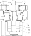
Fig. 9 is a topology view of a bar shaped vibration wave driving device, and this bar shaped vibration wave driving device has the vibrating elements of second embodiment.
As shown in the figure, in the bar shaped vibrating elements of present embodiment, one first elastic component 51, one second elastic component 52, a piezoelectric element 53 and a flange-shape elastic component 55 keep bolt/supporting pin 56 to be fixed tightly in together by a vibrating elements as fastener.In addition, the mating flanges 59 that will be engaged in the product of packing into is threaded with a part, and this part is that pin 56 is positioned at the locational part with second elastic component, 52 relative sides.An output gear 64 is installed on this mating flanges 59, around the central axis rotation of this vibrating elements.A rotor 60 is placed around first elastic component 51.This rotor 60 has been mounted a contact spring 61 and a spring box 62, and this contact spring 61 constitutes by the pressure form, is bonded and fixed on the outer circumferential sides of this rotor 60, and this spring box 62 is engaged on the inner circumferential side that is connected to this rotor 60.This spring box 62 is adjusted by its upper and lower end parts, and is fixed on the output gear 64 by its upper and lower end parts, thereby this spring box 62 can radially not move with respect to output gear 64.A spring that is used to exert pressure 63 is placed between these spring box 62 bottoms and the output gear 64.By the spring force of this spring 63, the spring terminal that contact spring 61 is fixed on the excircle part of rotor 60 contacts with the upper surface pressure of flange-shape elastic component 55.Mating flanges 59 also has the function of an additional mass, is used to prevent that vibration from keeping bolt/supporting pin 56 to reveal laterally from vibrating elements.
In the present embodiment, vibrating elements is fixed, and rotor as a contact by movable installation, this rotor contacts with this vibrating elements pressure.Yet the present invention not only is confined to this.This contact can be fixed, and vibrating elements simultaneously, is vibrated by the driving that generates in the flange-shape elastic component of vibrating elements by movable installation, this contact and this vibrating elements quilt be friction-driven relative to each other, and wherein this flange-shape elastic component stretches out with a flange forms.
Equally, in second to the 6th embodiment, though be not illustrated in the drawings, one will understand that the center surface of flange-shape elastic component is disposed on the position, this position does not conform to the position of the antinode of the flexural vibrations of bar shaped vibrating elements.
As mentioned above, the foregoing description has adopted a kind of structure, in this structure, a flange-shape elastic component with a friction surface is installed on the bar shaped vibrating elements, driving force obtains from this friction surface, in this structure, be processed with an elastic component that stretches out from this flange-shape elastic component, and resonant frequency is lowered by this spring-quality system simultaneously.Therefore, this spring can be done quite softly, thereby resonant frequency is lowered to an enough low level, that is to say, quite hour reduced when the diameter of this elastic component, resonant frequency also can be lowered to an enough low level.
In addition, when this elastic component that stretches out partly is made of metal, even when being out of shape situation about concentrating on this part, because the damping characteristic of metal material is better than the damping characteristic of piezoelectric element, so the increase of internal losses still rests in the minimum zone, has high efficiency short vibrating elements thereby can access one.
In addition, the driving force that is produced by the first row ripple can be added on the driving force that is produced by the second row ripple, and wherein the first row ripple is produced by the axis around the bar shaped vibrating elements, and the second row ripple is excited in the flange-shape elastic component.Therefore, be applied in the little signal of traditional signal, just can obtain an enough big driving force to an electric energy-mechanical energy conversion element by only applying a ratio.
In addition, because rotor can be placed around the elastic component that stretches out, the overall dimensions of motor also can be reduced.
Under the condition that does not deviate from thought of the present invention and substantive characteristics, can implement the present invention with other form.To take one thing with another all should be illustrative to the disclosed embodiments among the application, but not determinate.Scope of the present invention will show by appended claim, rather than shown by the declaratives of front, and changes all wherein involved in the institute of the appearance of the meaning that is equal to of claim and scope.
Claims (5)
1. vibration wave driving device, this vibration wave driving device comprise vibratory elements and rotor, this vibrating elements has the elastic component that electric energy-the mechanical energy conversion element is fixed thereon, this rotor contacts with the friction surface of this vibrating elements, and drive rotor by the row ripple, this row ripple is to be applied on electric energy-mechanical energy conversion element and to result from the lip-deep of this vibrating elements by driving signal; It is characterized in that,
Described vibrating elements comprises first elastic component, second elastic component and has the described elastic component of conduct the 3rd elastic component of described friction surface;
Described the 3rd elastic component and described electric energy-mechanical energy conversion element are placed between described first elastic component and described second elastic component;
Described rotor be positioned at described first elastic component near;
The first row ripple and the second row ripple form described capable ripple by superposeing, so that produce circular or oval-shaped motion at the friction surface of described the 3rd elastic component, wherein, the described first row ripple is formed by flexural vibrations, these flexural vibrations with the parallel plane direction displacement that comprises as the axis of the center of rotation of described capable ripple, the described second row ripple is formed by the hyperplane flexural vibrations that result from described the 3rd elastic component.
2. vibration wave driving device as claimed in claim 1 is characterized in that, described first elastic component and described the 3rd elastic component are processed to integral body.
3. vibration wave driving device as claimed in claim 1 is characterized in that at least one end parts of described vibrating elements has the diameter of increase.
4. vibration wave driving device as claimed in claim 1 is characterized in that, described the 3rd elastic component comprises the part of thinner thickness in the inner circumferential side with respect to described friction surface, and the thickness of this part is thinner than the part at described friction surface place.
5. vibration wave driving device as claimed in claim 1 is characterized in that, described vibrating elements also comprises another electric energy-mechanical energy conversion element, and this electric energy-mechanical energy conversion element is fixed on described the 3rd elastic component.
Applications Claiming Priority (4)
| Application Number | Priority Date | Filing Date | Title |
|---|---|---|---|
| JP013365/2001 | 2001-01-22 | ||
| JP2001013365 | 2001-01-22 | ||
| JP2002004198A JP3526298B2 (en) | 2001-01-22 | 2002-01-11 | Vibrating body and vibration wave driving device |
| JP004198/2002 | 2002-01-11 |
Publications (2)
| Publication Number | Publication Date |
|---|---|
| CN1367046A CN1367046A (en) | 2002-09-04 |
| CN1265896C true CN1265896C (en) | 2006-07-26 |
Family
ID=26608076
Family Applications (1)
| Application Number | Title | Priority Date | Filing Date |
|---|---|---|---|
| CNB021024553A Expired - Fee Related CN1265896C (en) | 2001-01-22 | 2002-01-22 | Vibrating element and vibrating wave driving device |
Country Status (6)
| Country | Link |
|---|---|
| US (1) | US6781283B2 (en) |
| EP (1) | EP1225682B1 (en) |
| JP (1) | JP3526298B2 (en) |
| KR (1) | KR100485882B1 (en) |
| CN (1) | CN1265896C (en) |
| DE (1) | DE60222035T2 (en) |
Families Citing this family (12)
| Publication number | Priority date | Publication date | Assignee | Title |
|---|---|---|---|---|
| JP3566711B2 (en) * | 2002-07-12 | 2004-09-15 | キヤノン株式会社 | Vibration wave drive |
| JP4742519B2 (en) * | 2004-05-14 | 2011-08-10 | コニカミノルタオプト株式会社 | Drive device using electromechanical transducer |
| KR100680307B1 (en) * | 2005-05-20 | 2007-02-07 | 삼성전기주식회사 | Piezoelectric vibrator and ultrasonic motor having same |
| JP4756916B2 (en) * | 2005-05-31 | 2011-08-24 | キヤノン株式会社 | Vibration wave motor |
| KR100704990B1 (en) * | 2005-08-08 | 2007-04-10 | 삼성전기주식회사 | Stator and Ceramic Tubular Ultrasonic Motor Using the Same |
| JP2012231595A (en) * | 2011-04-26 | 2012-11-22 | Canon Inc | Driving circuit for oscillation device, dust removing device, and driving circuit for oscillation device of oscillation type actuator |
| JP5932402B2 (en) * | 2012-03-07 | 2016-06-08 | キヤノン株式会社 | Vibration wave drive |
| JP6012226B2 (en) * | 2012-04-02 | 2016-10-25 | キヤノン株式会社 | Vibration wave driving device and driving circuit thereof |
| JP6184063B2 (en) | 2012-06-22 | 2017-08-23 | キヤノン株式会社 | Vibration wave driving device and electronic device |
| JP6053576B2 (en) * | 2013-03-01 | 2016-12-27 | キヤノン株式会社 | Vibration type driving device and imaging device |
| CN104113231A (en) * | 2014-06-24 | 2014-10-22 | 苏州世优佳电子科技有限公司 | Miniature ultrasonic focusing motor |
| CN105827146B (en) * | 2016-04-15 | 2018-01-19 | 南京航空航天大学 | For the vertical curved traveling wave piezoelectric vibrator and energisation mode for conveying and positioning |
Family Cites Families (27)
| Publication number | Priority date | Publication date | Assignee | Title |
|---|---|---|---|---|
| JPS60170472A (en) * | 1984-02-10 | 1985-09-03 | Canon Inc | Vibration wave motor |
| JPS61224880A (en) * | 1985-03-29 | 1986-10-06 | Canon Inc | Vibration wave motor |
| JPS61224881A (en) * | 1985-03-29 | 1986-10-06 | Canon Inc | Vibration wave motor |
| JPS61224882A (en) * | 1985-03-29 | 1986-10-06 | Canon Inc | Vibration wave motor |
| US4752711A (en) * | 1985-03-29 | 1988-06-21 | Canon Kabushiki Kaisha | Vibration wave motor |
| GB2183929B (en) | 1985-08-05 | 1989-11-15 | Canon Kk | Vibration wave motor |
| US4764702A (en) | 1985-12-30 | 1988-08-16 | Taga Electric Co., Ltd. | Ultrasonic motor device |
| US4812697A (en) * | 1986-04-09 | 1989-03-14 | Taga Electric Co., Ltd. | Ultrasonic vibrator and a method of controllingly driving same |
| JPS62262675A (en) * | 1986-05-09 | 1987-11-14 | Canon Inc | Oscillatory wave motor |
| DE3851781T2 (en) * | 1987-06-04 | 1995-02-16 | Seiko Instr Inc | Traveling wave motor. |
| EP0383309B1 (en) * | 1989-02-14 | 1997-06-04 | Canon Kabushiki Kaisha | Vibration wave motor |
| JP2874765B2 (en) * | 1989-06-19 | 1999-03-24 | キヤノン株式会社 | Vibration type motor device |
| JP2996477B2 (en) * | 1990-02-05 | 1999-12-27 | キヤノン株式会社 | Vibration wave drive |
| JP2998978B2 (en) * | 1990-08-03 | 2000-01-17 | キヤノン株式会社 | Vibration wave device and drive device |
| JP2879955B2 (en) * | 1990-08-03 | 1999-04-05 | キヤノン株式会社 | Vibration wave drive |
| JP2925272B2 (en) * | 1990-08-31 | 1999-07-28 | キヤノン株式会社 | Vibration wave motor |
| JP2803939B2 (en) * | 1992-01-23 | 1998-09-24 | キヤノン株式会社 | Vibration wave device |
| JP3167394B2 (en) * | 1992-01-29 | 2001-05-21 | キヤノン株式会社 | Vibration wave driving device and device having vibration wave driving device |
| JP3107933B2 (en) | 1992-12-03 | 2000-11-13 | キヤノン株式会社 | Vibration wave driving device and device provided with vibration wave driving device |
| JP3179601B2 (en) | 1992-12-17 | 2001-06-25 | キヤノン株式会社 | Vibration wave motor and device with vibration wave motor |
| JP3059031B2 (en) | 1993-09-22 | 2000-07-04 | キヤノン株式会社 | Vibration wave drive device and device provided with vibration wave drive device |
| US5949178A (en) | 1995-04-26 | 1999-09-07 | Canon Kabushiki Kaisha | Vibration wave driving apparatus and a vibration member, and manufacturing method of the apparatus and the member |
| JP4136037B2 (en) * | 1997-10-07 | 2008-08-20 | キヤノン株式会社 | Vibration type actuator and method for assembling vibration type actuator |
| JP3616712B2 (en) * | 1997-11-05 | 2005-02-02 | セイコーインスツル株式会社 | Ultrasonic motor and electronic equipment with ultrasonic motor |
| JP2000060152A (en) * | 1998-08-11 | 2000-02-25 | Mitsuba Corp | Ultrasonic motor |
| JP2001016875A (en) * | 1999-06-23 | 2001-01-19 | Canon Inc | Oscillatory wave drive device |
| JP2001145376A (en) | 1999-11-11 | 2001-05-25 | Canon Inc | Vibration wave derive device |
-
2002
- 2002-01-11 JP JP2002004198A patent/JP3526298B2/en not_active Expired - Fee Related
- 2002-01-17 US US10/047,108 patent/US6781283B2/en not_active Expired - Lifetime
- 2002-01-21 EP EP02001427A patent/EP1225682B1/en not_active Expired - Lifetime
- 2002-01-21 DE DE60222035T patent/DE60222035T2/en not_active Expired - Lifetime
- 2002-01-22 KR KR10-2002-0003486A patent/KR100485882B1/en active IP Right Grant
- 2002-01-22 CN CNB021024553A patent/CN1265896C/en not_active Expired - Fee Related
Also Published As
| Publication number | Publication date |
|---|---|
| DE60222035T2 (en) | 2008-06-05 |
| JP3526298B2 (en) | 2004-05-10 |
| DE60222035D1 (en) | 2007-10-11 |
| CN1367046A (en) | 2002-09-04 |
| EP1225682A2 (en) | 2002-07-24 |
| US20020096971A1 (en) | 2002-07-25 |
| KR20020062591A (en) | 2002-07-26 |
| EP1225682B1 (en) | 2007-08-29 |
| KR100485882B1 (en) | 2005-04-29 |
| JP2002291263A (en) | 2002-10-04 |
| US6781283B2 (en) | 2004-08-24 |
| EP1225682A3 (en) | 2005-07-27 |
Similar Documents
| Publication | Publication Date | Title |
|---|---|---|
| CN1265896C (en) | Vibrating element and vibrating wave driving device | |
| CN1879232A (en) | Ultrasonic lead screw motor | |
| CN1186825C (en) | Vibrating element and vibrating wave driving device | |
| CN1268442C (en) | Vibrator and vibration wave driving device with the vibrator | |
| CN103023372B (en) | The chip longitudinal-torsional ultrasound micro-motor of singlephase drive | |
| CN103001532B (en) | Chip longitudinal-torsional mode compound ultrasonic motor | |
| CN1835374A (en) | Multi-freedom ring stator supersonic dynamo | |
| CN1663057A (en) | Near-resonance electromechanical motor | |
| CN1153339C (en) | Vibration driven motor | |
| JP3059031B2 (en) | Vibration wave drive device and device provided with vibration wave drive device | |
| JPH05207761A (en) | Ultrasonic motor | |
| CN102710167A (en) | Bent oscillator stimulated rotary ultrasonic motor and electric excitation mode thereof | |
| CN1166049C (en) | Vibration drive | |
| CN101227157A (en) | Piezoelectric screw driver using Langevin vibrator structure | |
| CN101364775B (en) | Flat dual-stator thread driving ultrasonic minimized motor having thread pair pretensioning | |
| CN200959578Y (en) | Rotary standing-wave piezoelectric motor | |
| CN1258864C (en) | Ultrasonic Micromotors with Piezoelectric Columns with Conductive Shafts | |
| US8169723B2 (en) | Vibration actuator, lens barrel and camera | |
| CN102545689B (en) | Vibrational wave motor, lens barrel and camera | |
| CN1157916A (en) | Vibration actuator | |
| JPH0514512B2 (en) | ||
| Ishii et al. | An ultrasonic motor using transmission line and spiral structure driven by a Langevin transducer | |
| CN118748519A (en) | A single-phase excited and flattened mode conversion ultrasonic motor | |
| Ishii et al. | An ultrasonic motor using transmission line and horn with oblique slits driven by a Langevin transducer | |
| JPH0744856B2 (en) | Ultrasonic motor |
Legal Events
| Date | Code | Title | Description |
|---|---|---|---|
| C06 | Publication | ||
| PB01 | Publication | ||
| C10 | Entry into substantive examination | ||
| SE01 | Entry into force of request for substantive examination | ||
| C14 | Grant of patent or utility model | ||
| GR01 | Patent grant | ||
| CF01 | Termination of patent right due to non-payment of annual fee | ||
| CF01 | Termination of patent right due to non-payment of annual fee |
Granted publication date: 20060726 Termination date: 20200122 |