EP1225682B1 - Vibration wave driving apparatus - Google Patents
Vibration wave driving apparatus Download PDFInfo
- Publication number
- EP1225682B1 EP1225682B1 EP02001427A EP02001427A EP1225682B1 EP 1225682 B1 EP1225682 B1 EP 1225682B1 EP 02001427 A EP02001427 A EP 02001427A EP 02001427 A EP02001427 A EP 02001427A EP 1225682 B1 EP1225682 B1 EP 1225682B1
- Authority
- EP
- European Patent Office
- Prior art keywords
- elastic member
- vibration
- shaped elastic
- disc
- shaped
- Prior art date
- Legal status (The legal status is an assumption and is not a legal conclusion. Google has not performed a legal analysis and makes no representation as to the accuracy of the status listed.)
- Expired - Lifetime
Links
- 238000005452 bending Methods 0.000 claims description 45
- 238000006243 chemical reaction Methods 0.000 claims description 17
- 230000002093 peripheral effect Effects 0.000 claims description 12
- 238000006073 displacement reaction Methods 0.000 description 9
- 230000004323 axial length Effects 0.000 description 4
- 238000010586 diagram Methods 0.000 description 4
- 238000000034 method Methods 0.000 description 4
- 238000013016 damping Methods 0.000 description 3
- CNQCVBJFEGMYDW-UHFFFAOYSA-N lawrencium atom Chemical compound [Lr] CNQCVBJFEGMYDW-UHFFFAOYSA-N 0.000 description 3
- 230000003190 augmentative effect Effects 0.000 description 2
- 230000003247 decreasing effect Effects 0.000 description 2
- 239000000463 material Substances 0.000 description 2
- 239000002184 metal Substances 0.000 description 2
- 229910001369 Brass Inorganic materials 0.000 description 1
- 238000005299 abrasion Methods 0.000 description 1
- PNEYBMLMFCGWSK-UHFFFAOYSA-N aluminium oxide Inorganic materials [O-2].[O-2].[O-2].[Al+3].[Al+3] PNEYBMLMFCGWSK-UHFFFAOYSA-N 0.000 description 1
- 239000010951 brass Substances 0.000 description 1
- 239000000919 ceramic Substances 0.000 description 1
- 239000012141 concentrate Substances 0.000 description 1
- 238000010276 construction Methods 0.000 description 1
- 230000006866 deterioration Effects 0.000 description 1
- 238000010438 heat treatment Methods 0.000 description 1
- 239000007769 metal material Substances 0.000 description 1
- 230000001105 regulatory effect Effects 0.000 description 1
- 238000000926 separation method Methods 0.000 description 1
- 238000004904 shortening Methods 0.000 description 1
- 239000010409 thin film Substances 0.000 description 1
Images


Classifications
-
- H—ELECTRICITY
- H02—GENERATION; CONVERSION OR DISTRIBUTION OF ELECTRIC POWER
- H02N—ELECTRIC MACHINES NOT OTHERWISE PROVIDED FOR
- H02N2/00—Electric machines in general using piezoelectric effect, electrostriction or magnetostriction
-
- H—ELECTRICITY
- H02—GENERATION; CONVERSION OR DISTRIBUTION OF ELECTRIC POWER
- H02N—ELECTRIC MACHINES NOT OTHERWISE PROVIDED FOR
- H02N2/00—Electric machines in general using piezoelectric effect, electrostriction or magnetostriction
- H02N2/0005—Electric machines in general using piezoelectric effect, electrostriction or magnetostriction producing non-specific motion; Details common to machines covered by H02N2/02 - H02N2/16
- H02N2/001—Driving devices, e.g. vibrators
- H02N2/0015—Driving devices, e.g. vibrators using only bending modes
-
- H—ELECTRICITY
- H02—GENERATION; CONVERSION OR DISTRIBUTION OF ELECTRIC POWER
- H02N—ELECTRIC MACHINES NOT OTHERWISE PROVIDED FOR
- H02N2/00—Electric machines in general using piezoelectric effect, electrostriction or magnetostriction
- H02N2/10—Electric machines in general using piezoelectric effect, electrostriction or magnetostriction producing rotary motion, e.g. rotary motors
- H02N2/106—Langevin motors
Definitions
- the present invention relates to a vibration wave driving apparatus, and more particularly, to a configuration of a vibration element used in a bar-shaped vibration wave driving apparatus.
- a bar-shaped vibration wave driving apparatus includes, as a basic structure, a vibration element composed of elastic members made of metal or the like and a piezoelectric element as an electro-mechanical energy conversion element.
- the bar-shaped vibration wave driving apparatus generates a driving vibration such as a travelling wave or the like through application of an alternating voltage as an alternating signal with different phases to the piezoelectric element.
- a contact member is brought into pressure contact with a frictional surface of the elastic member through a pressurizing means and the contact member is frictionally driven by the driving vibration generated in the frictional surface of the elastic member to allow the vibration element and the contact member to be moved relative to each other.
- vibration wave motor as an example of such a vibration wave driving apparatus in which a vibration element is used as a stator and a contact member as a rotor.
- Examples of the vibration element of the vibration wave motor include those with a configuration in which a ring-shaped piezoelectric element plate is attached to one surface of a ring- or disc-shaped elastic member and those of a type in which the rotation of the rotor is taken out through an output shaft or of a type in which the rotation of the rotor is taken out directly.
- Such a vibration wave motor has been applied to products to be used for driving a camera lens and the like.
- FIG. 10A is a structural view of a vibration element of a bar-shaped vibration wave motor used for driving a camera lens.
- FIG. 10B shows a vibration mode (with the z-axis assigned to the axial direction and the r-axis assigned to the radial direction) in an axis part of the bar-shaped vibration element.
- Reference numeral 101 indicates a first elastic member; 102, a second elastic member; and 103, a piezoelectric element.
- Reference numeral 106 denotes a shaft member passing through the first elastic member 101, the piezoelectric element 103, and the second elastic member 102.
- One end of the shaft member 106 located on the side of a rotor 110 is fixed to a fitting member 109 to be attached to a product and the other end is fixed to a nut 115.
- a threaded portion is formed in the other end of the shaft member 106.
- Reference numeral 110 indicates the rotor as described above, and Reference numeral 107 denotes a friction member fixed to the first elastic element 101 to be in contact with the rotor.
- a vibration apparatus in such document is identical to a conventional product in that a piezoelectric element 203 is sandwiched and fixed between a first elastic member 201 and a second elastic member 202.
- the first elastic member 201 with a frictional surface is divided into an inner diameter portion and an outer diameter portion that are connected to each other through a thin connection part 210.
- connection part 210 when the connection part 210 is made thin to allow the resonance frequency to be lowered and its rigidity is deteriorated, the displacement generated in the piezoelectric element is absorbed by a soft spring of the connection part 210. Consequently, it is difficult to transmit the driving force to a rotor efficiently. Thus, it seems that there is still room for further improvement.
- JP 11-146669 Another piezoelectric vibration wave apparatus with an elastic member excited by a vibration generated by a piezoelectric element and driving a contact member by means of a frictional surface is disclosed in JP 11-146669 .
- One aspect of this invention is to provide a vibration wave driving apparatus including an electro-mechanical energy conversion element that is sandwiched and fixed between elastic members, wherein a third elastic member (disc shaped elastic member) is provided between the electro-mechanical energy conversion element and one of the elastic members.
- the third elastic member has a large diameter than that of the electro-mechanical energy conversion element.
- the output of the vibration wave driving apparatus can be improved.
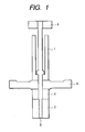
- Fig. 1 shows a first embodiment of the present invention.
- Reference numeral 1 denotes a first elastic member formed in a cylindrical shape, which is made of a material whose vibration damping loss is small, such as brass.
- Reference numeral 5 denotes a flange-shaped (disc-shaped) elastic member, which is made of ceramic, such as alumina.
- the vicinity of the outer periphery of the surface of the flange-shaped elastic member 5 located on the opposite side to an piezoelectric element 3 is a portion that comes into contact with a rotor and is formed to be slightly thicker like its center portion in which the flange or disc-shaped elastic member 5 is supported and fixed by the first elastic member 1.
- This is intended to reduce the area to be subjected to lapping process by allowing the region between the center portion and the vicinity of the outer periphery to be recessed, and thereby to reduce processing time.
- the vicinity of the outer periphery of the flange-shaped elastic member 5 extends outward beyond the outer peripheral portions of the first elastic member 1 and the piezoelectric element 3 that are adjacent to the flange-shaped elastic member 5.
- Reference numeral 3 denotes a group of piezoelectric elements.
- the group of piezoelectric elements one of a stacked type is disposed that is formed with a plurality of elements having electrodes on its both upper and lower sides or a plurality of thin-film piezoelectric members having electrodes on its both upper and lower sides stacked and hardened by heating to form one body.
- Reference numeral 2 indicates a second elastic member that also is formed of a material with a low vibration damping loss as in the case of the first elastic member 1.
- the first elastic member 1, the second elastic member 2, the flange-shaped elastic member 5, and the piezoelectric element 3 are combined to form one body by means of a shaft member 6 as a fastening means.
- the shaft member 6 with a threaded portion formed on its one end is inserted from the end portion of the first elastic member 1 to be passed through the piezoelectric element 3 and then the threaded portion is screwed together with an internal threaded portion formed in the axis center portion of the second elastic member 2.
- the flange-shaped elastic member 5 and the piezoelectric element 3 are disposed between the first elastic member 1 and the second elastic member 2 and in this state, the whole can be sandwiched and fixed by a flange portion provided for the shaft member 6 in its middle portion and the threaded portion provided at an end portion of the shaft member 6.
- the other end portion of the shaft member 6 is fixed to a fitting member 9 and supports the whole bar-shaped vibration element.
- the vibration element is formed so that all its members except the flange-shaped elastic member 5 have the same outer diameter.
- the position of the anti-node of the primary bending vibration which is displaced in a radial direction and is excited the above-mentioned bar-shaped vibration element is arranged in a position off the center surface of the flange-shaped elastic member 5.
- the "radial direction” used herein denotes a direction included in a plane orthogonal to a straight line passing through the respective centers of the first elastic member 1, the flange-shaped elastic member 5, the piezoelectric element 3, and the second elastic member 2.
- a higher-order vibration such as a second-or third-order vibration also may be used without causing any problem. In such a case, however, it is necessary to dispose the flange-shaped elastic member 5 in a position off the position of the anti-node of such a vibration.
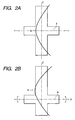
- a device having a vibration mode as shown in FIG. 2A is disclosed in Japanese Patent Application Laid-Open No. 4-91668 as one with a similar shape to that of the bar-shaped vibration element of the present embodiment.
- the flange-shaped elastic member makes only a translation motion in the radial direction by a primary bending vibration.
- the flange-shaped elastic member can excite a rotational motion about an axis perpendicular to the axis of the bar-shaped vibration element (the axis orthogonal to the x-axis and z-axis in FIG. 2B).
- the flange-shaped elastic member since the displacement including a thrust direction component and inertial force accompanying the displacement act on the vicinity of the outer periphery of the flange-shaped elastic member, the flange-shaped elastic member also can produce a vibration including the displacement component in the thrust direction, i.e. out-of-plane bending deformation.
- the inertial force as a force for exciting the bending vibration acting on the flange-shaped elastic member travels on the periphery of the flange-shaped elastic member and the out-of-plane bending vibration of the flange-shaped elastic member also travels accordingly.
- the location where the rotor and the vibration element is in contact with each other can be lowered and thereby the size of the whole vibration wave driving apparatus can be reduced.
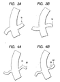
- FIGS. 3A and 3B each show a vibration mode in which a bending vibration of the bar and a bending vibration of the flange-shaped elastic member including no circle to be a node of the vibration are coupled with each other.
- FIGS. 4A and 4B each show a vibration mode in which a bending vibration of the bar and a bending vibration of the flange-shaped elastic member including one circle to be a node are coupled with each other.
- the directions at points B1 and B2 are opposite to each other in FIGS. 3A and 3B
- the directions at points B3 and B4 are opposite to each other in FIGS. 4A and 4B
- furthermore the directions at points B3 and B3' and the directions at points B4 and B4' each also are opposite to each other.
- the relationship between the points B3 and B3' and that between the points B4 and B4' each correspond to the relationship between the inside and outside of a node circle.
- the posture of vibrations largely depends on the relationship between the out-of-plane bending natural vibration frequency of the flange-shaped elastic member and the bending vibration frequency of the bar-shaped vibration element.
- the shape of the flange-shaped elastic member is determined so as to allow the generation of an out-of-plane bending vibration whose direction coincides with the rotation direction of the elliptical motion at the contact portion coming into contact with the rotor that is produced by the rotation of a bending vibration of the bar-shaped vibration element.
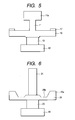
- FIG. 5 shows a second embodiment of the present invention.
- a flange-shaped elastic member 15 is formed integrally with a first elastic member 11, a piezoelectric element 13 is disposed between the flange-shaped elastic member 15 and a second elastic member 12, and the piezoelectric element 13 is sandwiched and fixed between the first elastic member 11 and the second elastic member 12 with an unshown fastening means.
- the fastening means for example, a screw member or the like may be used that is disposed inside the first and second elastic members 11 and 12 and passes through the piezoelectric element 13.
- the vibration element is configured so that its upper and lower ends have increased outer diameters by means of a portion 11a provided for the first elastic member 11 and the second elastic member 12. This allows the natural vibration frequency of the vibration element as a whole to be reduced and thereby allows the vibration element to have a shortened axial length as compared to those whose natural vibration frequency is equal to that of this vibration element.
- a member 17 having abrasion resistance is attached to a frictional portion subjected to friction with an unshown rotor on one surface of the outer peripheral portion of the flange-shaped elastic member 15 as a flange-shaped protruding portion. Since the frictional member 17 is disposed, it is no longer necessary to carry out lapping process with respect to the flange-shaped elastic member.
- FIG. 6 shows a third embodiment of the present invention.
- a vibration element of the present embodiment includes a first elastic member 21, a second elastic member 22, a piezoelectric element 23, and a flange-shaped elastic member 25 as well as an unshown fastening means as in the first embodiment.
- the present embodiment is different from the first embodiment in that a protrusion 25a is formed in the outer peripheral portion of the flange-shaped elastic member 25 and a circular groove 25b is provided on the inner peripheral side with respect to the protrusion 25a.
- the flange-shaped elastic member 25 is configured to have an increased weight at its outer peripheral end portion and lower stiffness on its inner peripheral side.
- an out-of-plane displacement is augmented in the outer peripheral portion of the flange that comes into contact with a rotor and thereby the rotational speed of the rotor further increases.
- FIGS. 7A and 7B show a fourth embodiment of the present invention
- FIG. 7A is a perspective view of a vibration element
- FIG. 7B is a cross-sectional view thereof.
- a flange-shaped elastic member 35 and a piezoelectric element 33 are sandwiched and fixed between a first elastic member 31 and a second elastic member 32.
- the present embodiment is different from those described above in that circumferential protrusions 35a are provided in the outer peripheral portion of the flange-shaped elastic member 35 and the protrusions 35a are separated from one another in the circumferential direction.
- FIG. 8 shows a vibration element according to a fifth embodiment of the present invention. This vibration element is obtained through further improvements made in the vibration element of the third embodiment.
- a piezoelectric element 43 for exciting an out-of-plane bending vibration is attached to the bottom face of a flange-shaped elastic member 25.
- a displacement is augmented using stretching force in the circumferential direction of the piezoelectric element.
- one used for driving the bar-shaped vibration element may be shared or another one may be provided.
- FIG. 9 is a structural view of a bar-shaped vibration wave driving apparatus with the vibration element of the second embodiment.
- a first elastic member 51, a second elastic member 52, a piezoelectric element 53, and a flange-shaped elastic member 55 are fastened together with a vibration element holding bolt/supporting pin 56 as a fastening member.
- a fitting flange 59 to be fitted into a product is screwed and joined with a portion of the pin 56 located on position opposite to the second elastic member 52.
- An output gear 64 is attached to the fitting flange 59 to be rotatable about the center of the axis of the vibration element.
- a rotor 60 is disposed around the first elastic member 51.
- the rotor 60 is provided with a contact spring 61 formed by press-forming that is adhesively secured thereto on its outer peripheral side and a spring case 62 that is engaged and joined therewith on inner peripheral side of the rotor 60.
- the spring case 62 is regulated by and fixed to the output gear 64 by its upper end portion so as not to be displaced relative to the output gear 64 in the radial direction.
- a spring 63 for applying pressing force is disposed between the lower end of the spring case 62 and the output gear 64. By the spring force of this spring 63, the spring end of the contact spring 61 fixed to the outer peripheral portion of the rotor 60 is in pressure contact with the upper surface of the flange-shaped elastic member 55.
- the fitting flange 59 also has a function of additional mass for preventing vibrations from leaking to the outside from the vibration element holding bolt/supporting pin 56.
- the vibration element is fixed and the rotor as a contact member that is brought into pressure contact with the vibration element is provided movably.
- the contact member may be fixed and the vibration element may be provided movably, and the vibration element and the contact member may be frictionally driven relative to each other by the driving vibration generated in the flange-shaped elastic member protruding in a flange form of the vibration element.
- the center surface of the flange-shaped elastic member is arranged in a position that does not coincide with the position of the anti-node of a bending vibration of the bar-shaped vibration element although it is not shown in the figures.
- the embodiment described above employs the configuration in which a flange-shaped elastic member with a frictional surface is provided for a bar-shaped vibration element and driving force is derived through the frictional surface as well as the configuration in which an elastic member protruding from the flange-shaped elastic member portion is provided and the resonance frequency is lowered with this spring-mass system.
- the spring can be made considerably soft so that the resonance frequency is decreased to a sufficiently low level, i.e. the resonance frequency can be decreased to a sufficiently low level even when the diameter of the elastic member is reduced considerably.
- the protruding elastic member portion is formed of metal, even in the case where distortion concentrates thereon, the increase in internal loss stays within a minimum range since damping characteristic of the metallic material is better than that of the piezoelectric element and thus a short vibration element with high efficiency can be obtained.
- driving force generated by a first travelling wave produced around the axis of the bar-shaped vibration element can be added driving force generated by a second travelling wave excited in the flange-shaped elastic member.
- driving force generated by a first travelling wave produced around the axis of the bar-shaped vibration element can be added driving force generated by a second travelling wave excited in the flange-shaped elastic member.
- the rotor can be disposed around the protruding elastic member, the overall length as the motor also is reduced.
- This invention relates to a vibration wave driving apparatus including an electro-mechanical energy conversion element that is sandwiched and fixed between elastic members, in which a flange-shaped elastic member is provided between the electro-mechanical energy conversion element and one of the elastic members.
- a vibration wave driving apparatus including an electro-mechanical energy conversion element that is sandwiched and fixed between elastic members, in which a flange-shaped elastic member is provided between the electro-mechanical energy conversion element and one of the elastic members.
Landscapes
- General Electrical Machinery Utilizing Piezoelectricity, Electrostriction Or Magnetostriction (AREA)
Description
- The present invention relates to a vibration wave driving apparatus, and more particularly, to a configuration of a vibration element used in a bar-shaped vibration wave driving apparatus.
- A bar-shaped vibration wave driving apparatus includes, as a basic structure, a vibration element composed of elastic members made of metal or the like and a piezoelectric element as an electro-mechanical energy conversion element. The bar-shaped vibration wave driving apparatus generates a driving vibration such as a travelling wave or the like through application of an alternating voltage as an alternating signal with different phases to the piezoelectric element.
- A contact member is brought into pressure contact with a frictional surface of the elastic member through a pressurizing means and the contact member is frictionally driven by the driving vibration generated in the frictional surface of the elastic member to allow the vibration element and the contact member to be moved relative to each other.
- There is a vibration wave motor as an example of such a vibration wave driving apparatus in which a vibration element is used as a stator and a contact member as a rotor.
- Examples of the vibration element of the vibration wave motor include those with a configuration in which a ring-shaped piezoelectric element plate is attached to one surface of a ring- or disc-shaped elastic member and those of a type in which the rotation of the rotor is taken out through an output shaft or of a type in which the rotation of the rotor is taken out directly.
- Such a vibration wave motor has been applied to products to be used for driving a camera lens and the like. There are annular type and bar-shaped type vibration wave motors.
- FIG. 10A is a structural view of a vibration element of a bar-shaped vibration wave motor used for driving a camera lens. FIG. 10B shows a vibration mode (with the z-axis assigned to the axial direction and the r-axis assigned to the radial direction) in an axis part of the bar-shaped vibration element.
-
Reference numeral 101 indicates a first elastic member; 102, a second elastic member; and 103, a piezoelectric element.Reference numeral 106 denotes a shaft member passing through the firstelastic member 101, thepiezoelectric element 103, and the secondelastic member 102. One end of theshaft member 106 located on the side of arotor 110 is fixed to afitting member 109 to be attached to a product and the other end is fixed to anut 115. A threaded portion is formed in the other end of theshaft member 106. With thenut 115 tightened, the firstelastic member 101, thepiezoelectric element 103, and the secondelastic member 102 disposed between a flange portion provided for theshaft member 106 and thenut 115 are sandwiched and fixed therebetween.Reference numeral 110 indicates the rotor as described above, andReference numeral 107 denotes a friction member fixed to the firstelastic element 101 to be in contact with the rotor. - When a driving signal is applied to the
piezoelectric element 103, the bending vibration (in FIG. 10B primary bending vibration) indicated in FIG. 10B is excited in the bar-shaped vibration element, whereby the bar-shaped vibration element makes a swing movement substantially about the z-axis. Accordingly, thefriction member 107 makes a circular motion around the z-axis. - It seems that the vibration element of such a bar-shaped vibration wave driving apparatus has been reduced in size in its radial direction, but there is still room for reduction in size in its thrust direction, i.e. in length of its axis.
- However, when the vibration element is simply shortened, there arise problems in that the resonance frequency increases and the vibration displacement is reduced, which causes the deterioration in efficiency of friction drive, the increase in price of a driving circuit element due to the high frequency, or the increase in loss inside the element. Further, when the vibration element is simply made thinner to lower the resonance frequency, the diameters of a piezoelectric element and a frictional surface are also reduced and thus generating force of the piezoelectric element and the friction torque also decrease. Therefore, it is conceivable that the output of the motor is made small.
- As a technique for solving the above problems and shortening the axial length of a bar-shaped vibration wave driving apparatus, there is one disclosed in
Japanese Patent Application Laid-open No. 2001-145376 - A vibration apparatus in such document is identical to a conventional product in that a
piezoelectric element 203 is sandwiched and fixed between a firstelastic member 201 and a secondelastic member 202. However, it is different from the conventional product in that the firstelastic member 201 with a frictional surface is divided into an inner diameter portion and an outer diameter portion that are connected to each other through athin connection part 210. - According to this construction, even if the axial length of the bar-shaped elastic member is shortened, a low resonance frequency can be obtained since the first vibration element has a sufficiently high mass.
- According to this technique, however, when the
connection part 210 is made thin to allow the resonance frequency to be lowered and its rigidity is deteriorated, the displacement generated in the piezoelectric element is absorbed by a soft spring of theconnection part 210. Consequently, it is difficult to transmit the driving force to a rotor efficiently. Thus, it seems that there is still room for further improvement. - Another piezoelectric vibration wave apparatus with an elastic member excited by a vibration generated by a piezoelectric element and driving a contact member by means of a frictional surface is disclosed in
JP 11-146669 - One aspect of this invention is to provide a vibration wave driving apparatus including an electro-mechanical energy conversion element that is sandwiched and fixed between elastic members, wherein a third elastic member (disc shaped elastic member) is provided between the electro-mechanical energy conversion element and one of the elastic members. The third elastic member has a large diameter than that of the electro-mechanical energy conversion element. When a driving vibration is applied to the electro-mechanical energy conversion element, a vibration element excites a bending vibration and this bending vibration allows an out-of-plane bending vibration to be excited in the third elastic member. Since a rotor is brought into contact with the third elastic member sandwiched between the elastic member and the electro-mechanical energy conversion element, the size of the vibration wave driving apparatus can be reduced. In addition, since a travelling wave produced by the bending vibrations of the vibration element and a travelling wave produced by the out-of-plane bending vibrations of the third elastic member are generated at the frictional surface of the vibration element, the output of the vibration wave driving apparatus can be improved.
-
- FIG. 1 is a cross-sectional view of a vibration element showing a first embodiment of the present invention.
- FIGS. 2A and 2B each are a vibration mode diagram used for explaining a driving principle of the present invention.
- FIGS. 3A and 3B each are a diagram illustrating a vibration mode of a vibration element showing a driving principle of the present invention.
- FIGS. 4A and 4B each are a diagram illustrating another vibration mode of a vibration element showing a driving principle of the present invention.
- FIG. 5 is a cross-sectional view of a vibration element showing a second embodiment of the present invention.
- FIG. 6 is a cross-sectional view of a vibration element showing a third embodiment of the present invention.
- FIGS. 7A and 7B are a perspective view and a cross-sectional view, respectively, of a vibration element showing a fourth embodiment of the present invention.
- FIG. 8 is a cross-sectional view of a vibration element showing a fifth embodiment of the present invention.
- FIG. 9 is a structural view of a vibration wave driving apparatus showing a sixth embodiment of the present invention.
- FIG. 10A is a cross-sectional view of a conventional bar-shaped vibration wave driving apparatus and FIG. 10B is a diagram illustrating a vibration mode of its vibration element.
- FIG. 11 is a cross-sectional view of a conventional vibration wave driving apparatus with a shortened axial length.
- The problem of the invention disclosed in
Japanese Patent Application Laid-open No. 2001-145376 - Fig. 1 shows a first embodiment of the present invention.
Reference numeral 1 denotes a first elastic member formed in a cylindrical shape, which is made of a material whose vibration damping loss is small, such as brass. Reference numeral 5 denotes a flange-shaped (disc-shaped) elastic member, which is made of ceramic, such as alumina. - In FIG. 1, the vicinity of the outer periphery of the surface of the flange-shaped elastic member 5 located on the opposite side to an
piezoelectric element 3 is a portion that comes into contact with a rotor and is formed to be slightly thicker like its center portion in which the flange or disc-shaped elastic member 5 is supported and fixed by the firstelastic member 1. This is intended to reduce the area to be subjected to lapping process by allowing the region between the center portion and the vicinity of the outer periphery to be recessed, and thereby to reduce processing time. In this case, as is apparent from FIG. 1, the vicinity of the outer periphery of the flange-shaped elastic member 5 extends outward beyond the outer peripheral portions of the firstelastic member 1 and thepiezoelectric element 3 that are adjacent to the flange-shaped elastic member 5. -
Reference numeral 3 denotes a group of piezoelectric elements. As the group of piezoelectric elements, one of a stacked type is disposed that is formed with a plurality of elements having electrodes on its both upper and lower sides or a plurality of thin-film piezoelectric members having electrodes on its both upper and lower sides stacked and hardened by heating to form one body. -
Reference numeral 2 indicates a second elastic member that also is formed of a material with a low vibration damping loss as in the case of the firstelastic member 1. - The first
elastic member 1, the secondelastic member 2, the flange-shaped elastic member 5, and thepiezoelectric element 3 are combined to form one body by means of ashaft member 6 as a fastening means. Theshaft member 6 with a threaded portion formed on its one end is inserted from the end portion of the firstelastic member 1 to be passed through thepiezoelectric element 3 and then the threaded portion is screwed together with an internal threaded portion formed in the axis center portion of the secondelastic member 2. The flange-shaped elastic member 5 and thepiezoelectric element 3 are disposed between the firstelastic member 1 and the secondelastic member 2 and in this state, the whole can be sandwiched and fixed by a flange portion provided for theshaft member 6 in its middle portion and the threaded portion provided at an end portion of theshaft member 6. The other end portion of theshaft member 6 is fixed to a fitting member 9 and supports the whole bar-shaped vibration element. In the present embodiment, the vibration element is formed so that all its members except the flange-shaped elastic member 5 have the same outer diameter. - When a driving signal is applied to the
piezoelectric element 3 from an unshown driving circuit, a primary bending vibration is excited in the bar-shaped vibration element thus formed and further a primary circumferential out-of-plane bending vibration including no circle to be a node of the vibration is excited in the flange-shaped elastic member 5. - At that time, the position of the anti-node of the primary bending vibration which is displaced in a radial direction and is excited the above-mentioned bar-shaped vibration element is arranged in a position off the center surface of the flange-shaped elastic member 5. The "radial direction" used herein denotes a direction included in a plane orthogonal to a straight line passing through the respective centers of the first
elastic member 1, the flange-shaped elastic member 5, thepiezoelectric element 3, and the secondelastic member 2. - As the bending vibration generated in the bar, a higher-order vibration such as a second-or third-order vibration also may be used without causing any problem. In such a case, however, it is necessary to dispose the flange-shaped elastic member 5 in a position off the position of the anti-node of such a vibration.
- Next, the following description is directed to the driving principle of the present invention.
- It has been known that when an out-of-plane bending vibration is excited in a disc and is allowed to travel, a circular or elliptical motion is produced at the surface of the disc.
- In this connection, a device having a vibration mode as shown in FIG. 2A is disclosed in
Japanese Patent Application Laid-Open No. 4-91668 center surface 8 of the flange-shaped elastic member coincides with the substantially center position A of the anti-node of a bending vibration of a bar as in the case of the mode shown in FIG. 2A, the flange-shaped elastic member makes only a translation motion in the radial direction by a primary bending vibration. - On the contrary, when the
center surface 8 of the flange-shaped elastic member is in a position off the center position A of the anti-node of the bending vibration of the bar-shaped vibration element whose mode is shown in FIG. 2B showing the present embodiment, besides the translation motion in the radial direction, the flange-shaped elastic member can excite a rotational motion about an axis perpendicular to the axis of the bar-shaped vibration element (the axis orthogonal to the x-axis and z-axis in FIG. 2B). Hence, since the displacement including a thrust direction component and inertial force accompanying the displacement act on the vicinity of the outer periphery of the flange-shaped elastic member, the flange-shaped elastic member also can produce a vibration including the displacement component in the thrust direction, i.e. out-of-plane bending deformation. In addition, since the bending vibration excited in the bar-shaped vibration element rotates about the axis, the inertial force as a force for exciting the bending vibration acting on the flange-shaped elastic member travels on the periphery of the flange-shaped elastic member and the out-of-plane bending vibration of the flange-shaped elastic member also travels accordingly. - It is a well-known phenomenon that the elliptical motion is produced at the flange-shaped elastic member surface when a travelling out-of-plane bending vibration is generated in a flange-shaped object. Hence, when the rotation direction of this elliptical motion is allowed to coincide with the rotation direction of a circular or elliptical motion produced in the flange-shaped elastic member by the rotation of the bending vibration of the bar-shaped vibration element, the rotational speed of a rotor pressed by the flange-shaped elastic member is increased and thereby the motor performance is improved.
- When the flange-shaped elastic member is provided below the center position of the anti-node of a bending vibration acting on the flange-shaped elastic member, the location where the rotor and the vibration element is in contact with each other can be lowered and thereby the size of the whole vibration wave driving apparatus can be reduced.
- FIGS. 3A and 3B each show a vibration mode in which a bending vibration of the bar and a bending vibration of the flange-shaped elastic member including no circle to be a node of the vibration are coupled with each other. FIGS. 4A and 4B each show a vibration mode in which a bending vibration of the bar and a bending vibration of the flange-shaped elastic member including one circle to be a node are coupled with each other.
- All the orders in the circumferential direction are 1 (1 wave).
- With respect to the direction of the circular or elliptical motion produced by the bending travelling wave of the flange-shaped elastic member, the directions at points B1 and B2 are opposite to each other in FIGS. 3A and 3B, the directions at points B3 and B4 are opposite to each other in FIGS. 4A and 4B, and furthermore the directions at points B3 and B3' and the directions at points B4 and B4' each also are opposite to each other. The relationship between the points B3 and B3' and that between the points B4 and B4' each correspond to the relationship between the inside and outside of a node circle.
- When driving the bar-shaped vibration element, the posture of vibrations largely depends on the relationship between the out-of-plane bending natural vibration frequency of the flange-shaped elastic member and the bending vibration frequency of the bar-shaped vibration element. Hence, the shape of the flange-shaped elastic member is determined so as to allow the generation of an out-of-plane bending vibration whose direction coincides with the rotation direction of the elliptical motion at the contact portion coming into contact with the rotor that is produced by the rotation of a bending vibration of the bar-shaped vibration element.
- FIG. 5 shows a second embodiment of the present invention.
- In a vibration element of a vibration wave driving apparatus of the present invention, a flange-shaped
elastic member 15 is formed integrally with a firstelastic member 11, apiezoelectric element 13 is disposed between the flange-shapedelastic member 15 and a secondelastic member 12, and thepiezoelectric element 13 is sandwiched and fixed between the firstelastic member 11 and the secondelastic member 12 with an unshown fastening means. As the fastening means, for example, a screw member or the like may be used that is disposed inside the first and secondelastic members piezoelectric element 13. - In the present embodiment, the vibration element is configured so that its upper and lower ends have increased outer diameters by means of a
portion 11a provided for the firstelastic member 11 and the secondelastic member 12. This allows the natural vibration frequency of the vibration element as a whole to be reduced and thereby allows the vibration element to have a shortened axial length as compared to those whose natural vibration frequency is equal to that of this vibration element. - Furthermore, in the present embodiment, a
member 17 having abrasion resistance is attached to a frictional portion subjected to friction with an unshown rotor on one surface of the outer peripheral portion of the flange-shapedelastic member 15 as a flange-shaped protruding portion. Since thefrictional member 17 is disposed, it is no longer necessary to carry out lapping process with respect to the flange-shaped elastic member. - FIG. 6 shows a third embodiment of the present invention.
- A vibration element of the present embodiment includes a first
elastic member 21, a secondelastic member 22, apiezoelectric element 23, and a flange-shapedelastic member 25 as well as an unshown fastening means as in the first embodiment. The present embodiment is different from the first embodiment in that aprotrusion 25a is formed in the outer peripheral portion of the flange-shapedelastic member 25 and acircular groove 25b is provided on the inner peripheral side with respect to theprotrusion 25a. - As a result, the flange-shaped
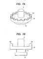
elastic member 25 is configured to have an increased weight at its outer peripheral end portion and lower stiffness on its inner peripheral side. Thus, an out-of-plane displacement is augmented in the outer peripheral portion of the flange that comes into contact with a rotor and thereby the rotational speed of the rotor further increases. - FIGS. 7A and 7B show a fourth embodiment of the present invention; FIG. 7A is a perspective view of a vibration element and FIG. 7B is a cross-sectional view thereof.
- Similarly in the present embodiment, a flange-shaped
elastic member 35 and apiezoelectric element 33 are sandwiched and fixed between a firstelastic member 31 and a secondelastic member 32. The present embodiment is different from those described above in thatcircumferential protrusions 35a are provided in the outer peripheral portion of the flange-shapedelastic member 35 and theprotrusions 35a are separated from one another in the circumferential direction. - Consequently, the stiffness is not increased when the flange-shaped
elastic member 35 is subjected to out-of-plane bending deformation. Hence, a considerable out-of-plane bending displacement is obtained. - In addition, since the circumferential displacement component of an elliptical motion produced by travel of the out-of-plane bending deformation of the flange-shaped
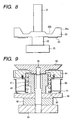
elastic member 35 is increased, it is possible to increase the rotational speed of a rotor, i.e. motor output. - FIG. 8 shows a vibration element according to a fifth embodiment of the present invention. This vibration element is obtained through further improvements made in the vibration element of the third embodiment.
- A
piezoelectric element 43 for exciting an out-of-plane bending vibration is attached to the bottom face of a flange-shapedelastic member 25. - When the inertial force alone is not sufficient to be used as the out-of-plane bending vibration exciting force, a displacement is augmented using stretching force in the circumferential direction of the piezoelectric element. As an alternating signal, one used for driving the bar-shaped vibration element may be shared or another one may be provided.
- FIG. 9 is a structural view of a bar-shaped vibration wave driving apparatus with the vibration element of the second embodiment.
- As shown in the figure, in the bar-shaped vibration element of the present embodiment, a first
elastic member 51, a secondelastic member 52, apiezoelectric element 53, and a flange-shapedelastic member 55 are fastened together with a vibration element holding bolt/supportingpin 56 as a fastening member. In addition, afitting flange 59 to be fitted into a product is screwed and joined with a portion of thepin 56 located on position opposite to the secondelastic member 52. Anoutput gear 64 is attached to thefitting flange 59 to be rotatable about the center of the axis of the vibration element. Arotor 60 is disposed around the firstelastic member 51. Therotor 60 is provided with acontact spring 61 formed by press-forming that is adhesively secured thereto on its outer peripheral side and aspring case 62 that is engaged and joined therewith on inner peripheral side of therotor 60. Thespring case 62 is regulated by and fixed to theoutput gear 64 by its upper end portion so as not to be displaced relative to theoutput gear 64 in the radial direction. Aspring 63 for applying pressing force is disposed between the lower end of thespring case 62 and theoutput gear 64. By the spring force of thisspring 63, the spring end of thecontact spring 61 fixed to the outer peripheral portion of therotor 60 is in pressure contact with the upper surface of the flange-shapedelastic member 55. Thefitting flange 59 also has a function of additional mass for preventing vibrations from leaking to the outside from the vibration element holding bolt/supportingpin 56. - In the present embodiment, the vibration element is fixed and the rotor as a contact member that is brought into pressure contact with the vibration element is provided movably. However, the present invention is not limited to this. The contact member may be fixed and the vibration element may be provided movably, and the vibration element and the contact member may be frictionally driven relative to each other by the driving vibration generated in the flange-shaped elastic member protruding in a flange form of the vibration element.
- Similarly in the second to sixth embodiments, it is to be understood that the center surface of the flange-shaped elastic member is arranged in a position that does not coincide with the position of the anti-node of a bending vibration of the bar-shaped vibration element although it is not shown in the figures.
- As described above, the embodiment described above employs the configuration in which a flange-shaped elastic member with a frictional surface is provided for a bar-shaped vibration element and driving force is derived through the frictional surface as well as the configuration in which an elastic member protruding from the flange-shaped elastic member portion is provided and the resonance frequency is lowered with this spring-mass system. Hence, the spring can be made considerably soft so that the resonance frequency is decreased to a sufficiently low level, i.e. the resonance frequency can be decreased to a sufficiently low level even when the diameter of the elastic member is reduced considerably.
- Furthermore, when the protruding elastic member portion is formed of metal, even in the case where distortion concentrates thereon, the increase in internal loss stays within a minimum range since damping characteristic of the metallic material is better than that of the piezoelectric element and thus a short vibration element with high efficiency can be obtained.
- In addition, to driving force generated by a first travelling wave produced around the axis of the bar-shaped vibration element can be added driving force generated by a second travelling wave excited in the flange-shaped elastic member. Hence, a sufficiently great driving force can be obtained through mere application of a smaller driving signal than conventional one to an electro-mechanical energy conversion element.
- Moreover, since the rotor can be disposed around the protruding elastic member, the overall length as the motor also is reduced.
- This invention relates to a vibration wave driving apparatus including an electro-mechanical energy conversion element that is sandwiched and fixed between elastic members, in which a flange-shaped elastic member is provided between the electro-mechanical energy conversion element and one of the elastic members. When a driving vibration is applied to the electro-mechanical energy conversion element, a vibration element excites bending vibrations and those bending vibrations allow out-of-plane bending vibrations to be excited in the flange-shaped elastic member. Since a rotor is brought into contact with the third elastic member sandwiched between the elastic member and the electro-mechanical energy conversion element, the size of the vibration wave driving apparatus can be reduced. In addition, since a travelling wave produced by the bending vibration of the vibration element and a travelling wave produced by the out-of-plane bending vibration of the third elastic member are generated at the frictional surface of the vibration element, the output of the vibration wave driving apparatus can be improved.
Claims (7)
- A vibration wave driving apparatus, comprising
a vibration element comprising a disc-shaped elastic member (5, 25, 35, 55) and an electro-mechanical energy conversion element (3, 23, 33, 53) fixed to the disc-shaped elastic member (5, 25, 35, 55), wherein the disc-shaped elastic member (5, 25, 35, 55) has a frictional surface, and
a rotor (60) contacting the frictional surface of the disc-shaped elastic member (5, 28, 35, 55),
wherein the electro-mechanical conversion element (3, 23, 33, 53) is arranged to excite upon application of a driving signal to it a first travelling wave on the frictional surface of the disc-shaped elastic member (5, 25, 35, 55) generated by out-of-plane bending vibrations of the disk-shaped elastic member (5, 25, 35, 55),
characterized
in that the vibration element furthermore comprises a first elastic member (1, 21, 31, 51) and a second elastic member (2, 22, 32, 52), wherein the first elastic member (1, 21, 31, 51), the disc-shaped elastic member (5, 25, 35, 55), the electro-mechanical energy conversion element (3, 23, 33, 53) and the second elastic member (2, 22, 32, 52) are arranged in the order as stated along an axial direction of the vibration element and are combined and fixed to form one body,
in that the disc-shaped elastic member (5, 25, 35, 55) has the frictional surface in the vicinity of its outer periphery, and
in that the diameter of the frictional surface is larger than the outer diameters of the first elastic member (1, 21, 31, 51) and of the electro-mechanical conversion element (3, 23, 33, 53),
wherein the disc-shaped elastic member (5, 28, 35, 55) is positioned along the axial direction of the vibration element such that the electro-mechanical conversion element (3, 23, 33, 53) furthermore excites a second travelling wave on the frictional surface of the disk-shaped elastic member (5, 25, 35, 55) generated by bending vibrations of the vibration element in a direction orthogonal to the axial direction thereof. - The vibration wave driving apparatus as set forth in claim 1, characterized in that the disc-shaped elastic member (5, 25, 35, 55) is disposed in a position that does not allow a center portion of the disc-shaped elastic member (5, 25, 35, 55) in the axial direction of the vibration element to coincide with a center (A) of an anti-node of the bending vibrations which are generated in a direction orthogonal to the axial direction of the vibration element.
- The vibration wave driving apparatus as set forth in any one of claims 1 and 2, characterized in that the disc-shaped elastic member (5, 25, 35, 55) has its frictional surface disposed on the side adjacent to the first elastic member (1, 21, 31, 51).
- The vibration wave driving apparatus as set forth in any one of claims 1 to 3, characterized in that an outer diameter of an end portion of the first elastic member (51) is formed larger than that of the opposite end portion of the first elastic member (51) which is in contact with the disc-shaped elastic member (55).
- The vibration wave driving apparatus as set forth in any one of claims 1 to 4, characterized in that the disc-shaped elastic member (25) includes a thin portion (25b) on an inner peripheral side with respect to the frictional surface.
- The vibration wave driving apparatus as set forth in claim 5, characterized in that the frictional surface of the disc-shaped elastic member (35) includes protrusions (35a) that are separated from one another in a circumferential direction.
- The vibration wave driving apparatus as set forth in any one of claims 1 to 6, characterized in that the disc-shaped elastic member (25) is provided with an additional electro-mechanical energy conversion element (43).
Applications Claiming Priority (4)
| Application Number | Priority Date | Filing Date | Title |
|---|---|---|---|
| JP2001013365 | 2001-01-22 | ||
| JP2001013365 | 2001-01-22 | ||
| JP2002004198A JP3526298B2 (en) | 2001-01-22 | 2002-01-11 | Vibrating body and vibration wave driving device |
| JP2002004198 | 2002-01-11 |
Publications (3)
| Publication Number | Publication Date |
|---|---|
| EP1225682A2 EP1225682A2 (en) | 2002-07-24 |
| EP1225682A3 EP1225682A3 (en) | 2005-07-27 |
| EP1225682B1 true EP1225682B1 (en) | 2007-08-29 |
Family
ID=26608076
Family Applications (1)
| Application Number | Title | Priority Date | Filing Date |
|---|---|---|---|
| EP02001427A Expired - Lifetime EP1225682B1 (en) | 2001-01-22 | 2002-01-21 | Vibration wave driving apparatus |
Country Status (6)
| Country | Link |
|---|---|
| US (1) | US6781283B2 (en) |
| EP (1) | EP1225682B1 (en) |
| JP (1) | JP3526298B2 (en) |
| KR (1) | KR100485882B1 (en) |
| CN (1) | CN1265896C (en) |
| DE (1) | DE60222035T2 (en) |
Families Citing this family (12)
| Publication number | Priority date | Publication date | Assignee | Title |
|---|---|---|---|---|
| JP3566711B2 (en) * | 2002-07-12 | 2004-09-15 | キヤノン株式会社 | Vibration wave drive |
| JP4742519B2 (en) * | 2004-05-14 | 2011-08-10 | コニカミノルタオプト株式会社 | Drive device using electromechanical transducer |
| KR100680307B1 (en) * | 2005-05-20 | 2007-02-07 | 삼성전기주식회사 | Piezoelectric Vibrator and Ultrasonic Motor Having Piezoelectric Vibrator |
| JP4756916B2 (en) * | 2005-05-31 | 2011-08-24 | キヤノン株式会社 | Vibration wave motor |
| KR100704990B1 (en) * | 2005-08-08 | 2007-04-10 | 삼성전기주식회사 | A stator and ceramic tube type ultrasonic motor using the same |
| JP2012231595A (en) * | 2011-04-26 | 2012-11-22 | Canon Inc | Driving circuit for oscillation device, dust removing device, and driving circuit for oscillation device of oscillation type actuator |
| JP5932402B2 (en) * | 2012-03-07 | 2016-06-08 | キヤノン株式会社 | Vibration wave drive |
| JP6012226B2 (en) * | 2012-04-02 | 2016-10-25 | キヤノン株式会社 | Vibration wave driving device and driving circuit thereof |
| JP6184063B2 (en) * | 2012-06-22 | 2017-08-23 | キヤノン株式会社 | Vibration wave driving device and electronic device |
| JP6053576B2 (en) * | 2013-03-01 | 2016-12-27 | キヤノン株式会社 | Vibration type driving device and imaging device |
| CN104113231A (en) * | 2014-06-24 | 2014-10-22 | 苏州世优佳电子科技有限公司 | Miniature ultrasonic focusing motor |
| CN105827146B (en) * | 2016-04-15 | 2018-01-19 | 南京航空航天大学 | For the vertical curved traveling wave piezoelectric vibrator and energisation mode for conveying and positioning |
Family Cites Families (27)
| Publication number | Priority date | Publication date | Assignee | Title |
|---|---|---|---|---|
| JPS60170472A (en) | 1984-02-10 | 1985-09-03 | Canon Inc | Vibration wave motor |
| JPS61224882A (en) | 1985-03-29 | 1986-10-06 | Canon Inc | Vibration wave motor |
| JPS61224880A (en) | 1985-03-29 | 1986-10-06 | Canon Inc | Vibration wave motor |
| US4752711A (en) | 1985-03-29 | 1988-06-21 | Canon Kabushiki Kaisha | Vibration wave motor |
| JPS61224881A (en) | 1985-03-29 | 1986-10-06 | Canon Inc | Vibration wave motor |
| GB2183929B (en) | 1985-08-05 | 1989-11-15 | Canon Kk | Vibration wave motor |
| US4764702A (en) | 1985-12-30 | 1988-08-16 | Taga Electric Co., Ltd. | Ultrasonic motor device |
| US4812697A (en) * | 1986-04-09 | 1989-03-14 | Taga Electric Co., Ltd. | Ultrasonic vibrator and a method of controllingly driving same |
| JPS62262675A (en) | 1986-05-09 | 1987-11-14 | Canon Inc | Oscillatory wave motor |
| DE3851781T2 (en) * | 1987-06-04 | 1995-02-16 | Seiko Instr Inc | Traveling wave motor. |
| EP0383309B1 (en) | 1989-02-14 | 1997-06-04 | Canon Kabushiki Kaisha | Vibration wave motor |
| JP2874765B2 (en) | 1989-06-19 | 1999-03-24 | キヤノン株式会社 | Vibration type motor device |
| JP2996477B2 (en) | 1990-02-05 | 1999-12-27 | キヤノン株式会社 | Vibration wave drive |
| JP2998978B2 (en) * | 1990-08-03 | 2000-01-17 | キヤノン株式会社 | Vibration wave device and drive device |
| JP2879955B2 (en) | 1990-08-03 | 1999-04-05 | キヤノン株式会社 | Vibration wave drive |
| JP2925272B2 (en) | 1990-08-31 | 1999-07-28 | キヤノン株式会社 | Vibration wave motor |
| JP2803939B2 (en) | 1992-01-23 | 1998-09-24 | キヤノン株式会社 | Vibration wave device |
| JP3167394B2 (en) | 1992-01-29 | 2001-05-21 | キヤノン株式会社 | Vibration wave driving device and device having vibration wave driving device |
| JP3107933B2 (en) | 1992-12-03 | 2000-11-13 | キヤノン株式会社 | Vibration wave driving device and device provided with vibration wave driving device |
| JP3179601B2 (en) | 1992-12-17 | 2001-06-25 | キヤノン株式会社 | Vibration wave motor and device with vibration wave motor |
| JP3059031B2 (en) | 1993-09-22 | 2000-07-04 | キヤノン株式会社 | Vibration wave drive device and device provided with vibration wave drive device |
| US5949178A (en) | 1995-04-26 | 1999-09-07 | Canon Kabushiki Kaisha | Vibration wave driving apparatus and a vibration member, and manufacturing method of the apparatus and the member |
| JP4136037B2 (en) * | 1997-10-07 | 2008-08-20 | キヤノン株式会社 | Vibration type actuator and method for assembling vibration type actuator |
| JP3616712B2 (en) * | 1997-11-05 | 2005-02-02 | セイコーインスツル株式会社 | Ultrasonic motor and electronic equipment with ultrasonic motor |
| JP2000060152A (en) * | 1998-08-11 | 2000-02-25 | Mitsuba Corp | Ultrasonic motor |
| JP2001016875A (en) * | 1999-06-23 | 2001-01-19 | Canon Inc | Oscillatory wave drive device |
| JP2001145376A (en) | 1999-11-11 | 2001-05-25 | Canon Inc | Vibration wave derive device |
-
2002
- 2002-01-11 JP JP2002004198A patent/JP3526298B2/en not_active Expired - Fee Related
- 2002-01-17 US US10/047,108 patent/US6781283B2/en not_active Expired - Lifetime
- 2002-01-21 EP EP02001427A patent/EP1225682B1/en not_active Expired - Lifetime
- 2002-01-21 DE DE60222035T patent/DE60222035T2/en not_active Expired - Lifetime
- 2002-01-22 KR KR10-2002-0003486A patent/KR100485882B1/en active IP Right Grant
- 2002-01-22 CN CNB021024553A patent/CN1265896C/en not_active Expired - Fee Related
Non-Patent Citations (1)
| Title |
|---|
| None * |
Also Published As
| Publication number | Publication date |
|---|---|
| EP1225682A2 (en) | 2002-07-24 |
| US6781283B2 (en) | 2004-08-24 |
| KR20020062591A (en) | 2002-07-26 |
| JP3526298B2 (en) | 2004-05-10 |
| KR100485882B1 (en) | 2005-04-29 |
| DE60222035D1 (en) | 2007-10-11 |
| CN1265896C (en) | 2006-07-26 |
| CN1367046A (en) | 2002-09-04 |
| EP1225682A3 (en) | 2005-07-27 |
| US20020096971A1 (en) | 2002-07-25 |
| DE60222035T2 (en) | 2008-06-05 |
| JP2002291263A (en) | 2002-10-04 |
Similar Documents
| Publication | Publication Date | Title |
|---|---|---|
| US7215063B2 (en) | Vibration element and vibration wave driving apparatus | |
| JP3059031B2 (en) | Vibration wave drive device and device provided with vibration wave drive device | |
| EP1225682B1 (en) | Vibration wave driving apparatus | |
| EP0740353B1 (en) | A vibriation wave driving apparatus and a vibration member | |
| EP0600484A1 (en) | Vibration driven motor | |
| JPH1146486A (en) | Vibration actuator and manufacture of vibration-body tightening member in the actuator | |
| JP4435695B2 (en) | Piezoelectric motor operation method and piezoelectric motor in the form of a hollow cylindrical oscillator having a stator | |
| JP2002291263A5 (en) | ||
| JP2926765B2 (en) | Ultrasonic motor | |
| JPH11164575A (en) | Oscillatory motor | |
| JP2002218774A (en) | Ultrasonic motor | |
| JP4095282B2 (en) | Vibration wave drive | |
| EP4275462B1 (en) | Mounting arrangement for piezo motor element | |
| JPH02311184A (en) | Ultrasonic motor | |
| JP2549309B2 (en) | Ultrasonic motor | |
| JP2001016875A (en) | Oscillatory wave drive device | |
| JPH01177878A (en) | Oscillatory wave motor | |
| JP3089750B2 (en) | Ultrasonic motor | |
| JPH1094274A (en) | Apparatus with vibration driver | |
| JPH11262281A (en) | Progressive-wave piezoelectric motor | |
| JPH0789746B2 (en) | Surface wave motor | |
| JPH02266877A (en) | Ultrasonic motor | |
| JPH0336972A (en) | Ultrasonic motor | |
| JP2003047263A (en) | Oscillatory wave drive | |
| JPH03190575A (en) | Ultrasonic motor |
Legal Events
| Date | Code | Title | Description |
|---|---|---|---|
| PUAI | Public reference made under article 153(3) epc to a published international application that has entered the european phase |
Free format text: ORIGINAL CODE: 0009012 |
|
| AK | Designated contracting states |
Kind code of ref document: A2 Designated state(s): AT BE CH CY DE DK ES FI FR GB GR IE IT LI LU MC NL PT SE TR |
|
| AX | Request for extension of the european patent |
Free format text: AL;LT;LV;MK;RO;SI |
|
| PUAL | Search report despatched |
Free format text: ORIGINAL CODE: 0009013 |
|
| AK | Designated contracting states |
Kind code of ref document: A3 Designated state(s): AT BE CH CY DE DK ES FI FR GB GR IE IT LI LU MC NL PT SE TR |
|
| AX | Request for extension of the european patent |
Extension state: AL LT LV MK RO SI |
|
| 17P | Request for examination filed |
Effective date: 20060127 |
|
| AKX | Designation fees paid |
Designated state(s): DE FR GB |
|
| GRAP | Despatch of communication of intention to grant a patent |
Free format text: ORIGINAL CODE: EPIDOSNIGR1 |
|
| GRAS | Grant fee paid |
Free format text: ORIGINAL CODE: EPIDOSNIGR3 |
|
| GRAA | (expected) grant |
Free format text: ORIGINAL CODE: 0009210 |
|
| AK | Designated contracting states |
Kind code of ref document: B1 Designated state(s): DE FR GB |
|
| REG | Reference to a national code |
Ref country code: GB Ref legal event code: FG4D |
|
| REF | Corresponds to: |
Ref document number: 60222035 Country of ref document: DE Date of ref document: 20071011 Kind code of ref document: P |
|
| ET | Fr: translation filed | ||
| PLBE | No opposition filed within time limit |
Free format text: ORIGINAL CODE: 0009261 |
|
| STAA | Information on the status of an ep patent application or granted ep patent |
Free format text: STATUS: NO OPPOSITION FILED WITHIN TIME LIMIT |
|
| 26N | No opposition filed |
Effective date: 20080530 |
|
| REG | Reference to a national code |
Ref country code: FR Ref legal event code: PLFP Year of fee payment: 15 |
|
| PGFP | Annual fee paid to national office [announced via postgrant information from national office to epo] |
Ref country code: GB Payment date: 20160127 Year of fee payment: 15 Ref country code: FR Payment date: 20160126 Year of fee payment: 15 |
|
| GBPC | Gb: european patent ceased through non-payment of renewal fee |
Effective date: 20170121 |
|
| REG | Reference to a national code |
Ref country code: FR Ref legal event code: ST Effective date: 20170929 |
|
| PG25 | Lapsed in a contracting state [announced via postgrant information from national office to epo] |
Ref country code: FR Free format text: LAPSE BECAUSE OF NON-PAYMENT OF DUE FEES Effective date: 20170131 |
|
| PG25 | Lapsed in a contracting state [announced via postgrant information from national office to epo] |
Ref country code: GB Free format text: LAPSE BECAUSE OF NON-PAYMENT OF DUE FEES Effective date: 20170121 |
|
| PGFP | Annual fee paid to national office [announced via postgrant information from national office to epo] |
Ref country code: DE Payment date: 20190401 Year of fee payment: 18 |
|
| REG | Reference to a national code |
Ref country code: DE Ref legal event code: R119 Ref document number: 60222035 Country of ref document: DE |
|
| PG25 | Lapsed in a contracting state [announced via postgrant information from national office to epo] |
Ref country code: DE Free format text: LAPSE BECAUSE OF NON-PAYMENT OF DUE FEES Effective date: 20200801 |