JP4095282B2 - Vibration wave drive - Google Patents
Vibration wave drive Download PDFInfo
- Publication number
- JP4095282B2 JP4095282B2 JP2001355912A JP2001355912A JP4095282B2 JP 4095282 B2 JP4095282 B2 JP 4095282B2 JP 2001355912 A JP2001355912 A JP 2001355912A JP 2001355912 A JP2001355912 A JP 2001355912A JP 4095282 B2 JP4095282 B2 JP 4095282B2
- Authority
- JP
- Japan
- Prior art keywords
- vibration
- driving device
- vibrating body
- vibration wave
- vibrating
- Prior art date
- Legal status (The legal status is an assumption and is not a legal conclusion. Google has not performed a legal analysis and makes no representation as to the accuracy of the status listed.)
- Expired - Fee Related
Links
Images


Landscapes
- General Electrical Machinery Utilizing Piezoelectricity, Electrostriction Or Magnetostriction (AREA)
Description
【0001】
【発明の属する技術分野】
本発明は振動波駆動装置、特に振動体の構造に関する。
【0002】
【従来の技術】
振動波モータ等の振動波駆動装置は、駆動振動が形成される振動体を基本的構成として有し、該振動体の駆動部に接触体が加圧接触し、前記移動体と前記接触体とが前記駆動振動により相対移動する。そして、このような振動波モータは、カメラレンズ駆動用途等への製品応用がなされており、棒状型のものと円環型のものが存在する。
【0003】
図12は現在カメラレンズ駆動用に用いられている棒状型の振動波モータの構成図を示す。図12において、aは金属製の第1の弾性体、bは金属製の第2の弾性体、cは積層型の電気−機械エネルギー変換素子としての積層圧電素子、d1はシャフト、d2はナットであり、部品aからcは該シャフトd1及びナットd2によって所定の挟持力が付与されるように締め付けられている。
【0004】
ロータgはロータ本体の振動体側に筒状の摩擦接触部材を嵌合した構成を有し、この摩擦接触部材は接触幅が小さく、かつ適度なバネ性を有する構造をしており、この摩擦接触部材の先端面が振動体の摩擦面fに接触する。また、ロータgの前記振動体とは反対側には、ロータと一緒に回転し、モータの出力を伝達するギアhの凹部(または凸部)と係合するよう凸部(または凹部)が形成されている。さらに、ギアhはモータを不図示の被取付け部に取り付けるためのフランジiにより、シャフトd1のスラスト方向に位置が固定されており、前記ロータgに加圧力を付与するための加圧バネjがこのギアとロータとの間に設けられている。
【0005】
前記積層圧電素子cは、片面側に複数の電極が形成され、電極が2つの電極群にグループ化されており、不図示の電源からそれぞれの電極群に位相の異なる交流電界を印加すると、振動体には図13(b)に示す姿態の直交する2つの曲げ振動が励振される(もう一方は紙面に垂直な方向の振動)。この印加電界の位相を調整することにより、2つの振動間に90度の時間的な位相差を与えることができる。その結果、棒状振動体の曲げ振動は振動体の軸周りに回転する。
【0006】
この結果、ロータgに接触する第1の弾性体aの上面には楕円運動が形成され、耐摩耗性を有する摩擦面fに押圧されたロータgが摩擦駆動されるため、該ロータg、ギアh、加圧バネjが一体となって回転する。
【0007】
【発明が解決しようとする課題】
電気-機械エネルギー変換素子に交流電界を印加することによって、振動体上に同形のモードの振動を時間的に適当な位相差を有して励起させ、該振動体の表面粒子に円又は楕円運動を行なわしめる振動体において、安定した性能を供給するために、性能に大きく関与する進行波ムラを減らす手法として、2つの共振周波数差Δf(=fa-fb)を10Hz≦fa-fb≦100Hzに設定していた。Δfと駆動部各所での振動波の大きさのばらつきの関係を図14示す。図14から分かるように、A相のQ値(Qa)とB相のQ値(Qb)が同じ値の場合には、Δfが増加すればするほど、振動波の大きさのばらつきが大きくなることから、2つの共振周波数差を調整するだけでは、完全に進行波ムラを無くすことができないという課題を抱えていた。
【0008】
また、世の中のニーズとして、更に性能を向上させたいという要望がある。この要望に応えるために、進行波ムラ成分の発生の要因となる駆動部各所での振動波の大きさのばらつきを小さくするために、減衰成分を意図的に調整することにより(Qa/Qbの値を調整する)、図14に示すように振動波の大きさのばらつきを小さくし、進行波ムラを抑え、性能を向上させることに努めた。
【0009】
また、2つの固有振動数に差を設ける手段として、図12の現在カメラレンズ駆動用に用いられている棒状型の振動体においては、2面取りという手法が採用されていた。
【0010】
しかし、この手法では、加工工程が煩雑になるためコストアップ要因につながり、コストが高くなるという課題があった。世の中のニーズとして、さらに安くしたいという要望がある。この要望に応えるために、給電用部材の電極パターン又は形状を非対称に構成したり、振動体の挟持面に非対称形な金属部材を挟持固定した。
【0011】
また、第1の弾性体aを回してねじ締め用のトルクをシャフトd1に伝達するために、第1の弾性体aには、シャフト軸方向に窪みを持つスリットが周方向に設けられ、このスリットにねじ締め治具を差し込んでねじ締めを行なうようにしており、このようにして形成された動剛性不均一部により2つの振動系の固有振動数に差を設けることにより、コストダウンを実現した。
【0012】
本出願に係る発明の目的は、このような点に鑑み、駆動振動のムラの原因となる駆動部各所での振動波の大きさのばらつきを小さくすることができる振動体を備えた振動波駆動装置を提供しようとするものである。
【0013】
また、本出願に係る発明の他の目的は、このような点に鑑み、駆動振動のムラの原因となる駆動部各所での振動波の大きさを自由に設定できる振動体を備えた振動波駆動装置を提供しようとするものである。
【0014】
【課題を解決するための手段】
本発明は、電気-機械エネルギー変換素子に交流電圧を印加することによって弾性体の駆動部に同形の2つの振動モードの振動を時間的に適当な位相差を有して励起させ、該位相差を有する振動の合成により該弾性体に円または楕円運動を形成する振動体、振動体に加圧接触する移動体を有する振動波駆動装置において、前記2つの振動モードにおける振動体の固有振動数に差を設けるとともに、2つの振動モードのうち固有振動数の高い振動モードにおける振動体の機械的品質係数Q値を固有振動数の低い振動モードにおける振動体の機械的品質係数Q値よりも低くしたことを特徴とする。
【0024】
ここで、固有振動数の高い方の機械的品質係数 Q 値を低くして、進行波ムラの原因となる駆動部各所での振動波の大きさのばらつきを小さくするためには、振動体に減衰性の部材を設ける構成にすればよい。
【0025】
また、給電部材の電極パターン又は形状を2つの振動モードの振動方向に関して互いに異なる構成(非対称)にしたり、2つの振動モードの振動方向に関して異なる形状を有する金属部材を配置する構成にしたりする。
【0026】
また、弾性体に、2つの振動モードにおける振動方向で弾性体の剛性に差を持たせるスリットを設けたりする構成にすればよい。
【0027】
【発明の実施の形態】
(第1の実施の形態)
図1、図2は本発明の第1の実施の形態である。
【0028】
本第1の実施の形態では、図2(a)に示すように、ディスク状弾性体eと第2の弾性体bにより電気−機械エネルギー変換素子としての積層圧電素子cを挟持固定し、圧入構造で第1の弾性体aと一体化されているシャフトd1と、第2の弾性体bの両ねじ部とを結合し、締め付けるように振動体が構成されている。
【0029】
なお、振動体を一体化するための圧入構造及び下のねじ構造部は、それぞれ、ねじ構造、テーパ構造、圧入構造、一体加工構造、キー構造、蝋付け構造等でもよい。
【0030】
本実施の形態において、積層圧電素子cは、圧電層と電極層を交互に複数層形成したもので、複数の電極層において電極が2つの電極群にグループ化されており、不図示の電源からそれぞれの電極群に位相の異なる交流電界を印加すると、振動体には図2(b)に示す姿態の直交する2つの曲げ振動が励振される(もう一方は紙面に垂直な方向の振動)。この印加電界の位相を調整することにより、2つの振動間に90度の時間的な位相差を与えることができる。その結果、棒状振動体の曲げ振動は振動体の軸周りに回転する。
【0031】
これらの振動体を励振するために、積層圧電素子cの圧電層の片面に形成される電極層は、円盤部を略4等分する形状で電極が形成され、各電極の外端の一部から延びる側面電極が圧電層の外端面に形成されている。
【0032】
積層圧電素子cは、各電極ごとに圧電層が厚さ方向に分極が施されており、中心軸に対して対向する位置にある電極は互いに逆方向に分極されている。各電極には積層圧電素子cの側面において前記側面電極が一体的に導通され、そこに給電用のリード線が半田付けにより接続されている。
【0033】
また、複数の電極層の一つには、図3に示すように、センサ相電極を有するものがある。電極3AがA相電極、電極3B1及び3B2がB相電極、電極3Sがセンサ相電極である。
【0034】
積層圧電素子の電極は振動体の屈曲変形により歪みを生じ、圧電効果により電荷を発生する。この電荷を電極Sより検出することで振動体の振動状態のモニターが行われる。この時の周波数に対するA相圧電素子の印加電圧とセンサ相の出力信号の位相差の関係(以後θA-Sと称する)は、屈曲1次振動モードで振動体を駆動すると、共振周波数frにおいて位相差θA-Sは、CW(時計周り方向)、CCW(反時計周り方向)共にπ/2[rad]となり、共振周波数より高い側の周波数では徐々にずれていく。よって、振動を与えている時にこの位相差θA-Sの値を検出することで入力の周波数と振動体の共振周波数との関係のモニターが行え、振動体の安定した駆動が行える。
【0035】
従来、安定した駆動を行うために、2つの共振周波数差Δf(=fa-fb)を10[Hz]≦fa-fb≦100[Hz]に設定し、θA-Sの値を検出し、制御を行っていた。
【0036】
本実施の形態では、さらに安定した駆動を行うため、進行波ムラの原因となる駆動部各所での振動波の大きさのばらつきを小さくするために、図1に示すように、固有振動数の高い方つまりA相の振動系の機械的品質係数Q(∝Y)を低く設定した。
【0037】
本実施の形態においては、A相の振動系における振動体に振動減衰性に優れた部材を付与または付加することにより機械的品質係数Qを低く設定した。
【0038】
図14に示すように、A相とB相のQ値、つまりQa/Qbの値を調整することにより、進行波ムラの原因となる駆動部各所での振動波の大きさのばらつきを小さくすることができる。
【0039】
(第2の実施の形態)
図4は本発明の第2の実施の形態を示す。なお、図2に示す部材と同じ部材には同じ符号を付してその説明を省略する。
【0040】
本実施の形態では、棒状振動体において、駆動部各所での振動波の大きさを自由に設定するために、第1の弾性体aとディスク状弾性体eの挟持面及び、圧電素子cの外周部、第2の弾性体bの外周部に接着剤又はゴムなどの減衰性の部材pを配置するように構成した。
【0041】
これらの減衰性の部材pは、A相曲げ方向の領域に設けられている。
【0042】
なお、図4は配置場所の一例であり、本発明は図示の場所に限定されるものではない。
【0043】
(第3の実施の形態)
図5は本発明の第3の実施の形態を示す。
【0044】
本実施の形態では、円環型振動体において、駆動部各所での振動波の大きさを自由に設定するために、振動の腹位置に接着剤又はゴムなどの減衰性の部材pを配置するように構成している。
【0045】
この振動体は、リング状弾性体aの一方の面にリング状の圧電素子cを接着したもので、リング状の圧電素子cは、振動の波長をλとすると、例えばλ/2の間隔で分極方向が互いに異なる複数の電極を2群有し、両電極群の間隔をλ/4としたものである。
【0046】
図5(b)は、面外3次の曲げ振動の時に減衰性部材を配置する位置を示した一例であり、弾性体aと圧電素子cとの間に減衰性部材pを配置しており、例えば円板状の部材の一部に減衰性部材pを設けている。なお、減衰性部材pは図示の場所に限定されるものではない。例えば減衰性部材pを櫛歯の間に設けてもよく、また櫛歯自体を減衰性部材としても良い。
【0047】
この図5(b)の場合、振動の腹に減衰性の部材pを配置していることを示している。なお、減衰性の部材pはA相の定在波振動における腹の位置に配置されているものである。
【0048】
また、弾性体aの上面には切り込みrを設けることにより、振動体の2つの固有振動数に差を設けている。
【0049】
(第4の実施の形態)
図6は本発明の第4の実施の形態である。
【0050】
本発明では、棒状振動体の固有振動数差を設ける手段として、給電用フレキ(フレキシブルプリント配線板)のパターン部(ハッチング部)におけるスリット部をA相方向に設けることで、B相方向の剛性を小さくするように構成されている。
【0051】
勿論、第1の実施の形態と同様に、2つの振動系の固有振動数に差を有し、固有振動数の高い方の振動系における機械的品質係数Q値を他方の振動系の機械的品質係数Q値よりも低く設定している。
【0052】
(第5の実施の形態)
図7は本発明の第5の実施の形態である。
【0053】
本発明では、棒状振動体の固有振動数差を設ける手段として、給電用フレキの取り出し口をB相方向に設けることで、A相方向の剛性を大きくするように構成されている。すなわち、A相方向の剛性は、フレキの取り出し方向と垂直方向にフレキの取り出し分を曲げるため、A相方向の剛性が大きくなる。
【0054】
勿論、第1の実施の形態と同様に、2つの振動系の固有振動数に差を有し、固有振動数の高い方の振動系における機械的品質係数Q値を他方の振動系の機械的品質係数Q値よりも低く設定している。
【0055】
(第6の実施の形態)
図8、図9は本発明の第6の実施の形態を示す。
【0056】
本発明では、棒状振動体の固有振動数差を設ける手段として、振動体の挟持面に、図9(a)または(b)に示すように、非対称形に構成された金属部材sを、任意の挟持面に少なくとも1つ以上挟持固定するように構成しており、例えば第1の弾性体aとディスク状弾性体eとの間、ディスク状弾性体eと圧電素子cとの間に金属部材sを設けている。なお、図8(a)は配置場所の一例であり、本発明は図示の場所に限定されるものではない。
【0057】
勿論、第1の実施の形態と同様に、2つの振動系の固有振動数に差を有し、固有振動数の高い方の振動系における機械的品質係数Q値を他方の振動系の機械的品質係数Q値よりも低く設定している。
【0058】
(第7の実施の形態)
図10は本発明の第7の実施の形態を示す。
【0059】
本実施の形態では、第1の弾性体aを回してねじ締め用のトルクをシャフトd1に伝達するために、第1の弾性体aには、シャフト軸方向に窪みを持つスリットが周方向に設けられ、このスリットにねじ締め治具を差し込んでねじ締めを行なうようにしている。図10はスリットの形状の実施の形態である。
【0060】
図10におけるスリットの形状は、(a)直線、(b)三叉路をそれぞれ示している。(a),(b)ともに中心点から放射状にスリットが延びる構成になっているが、この放射状のスリットの数は、2、3本に限定されるものではなく、第1の弾性体に剛性差を持たせるようなスリット形状になっていればよい。
【0061】
勿論、第1の実施の形態と同様に、2つの振動系の固有振動数に差を有し、固有振動数の高い方の振動系における機械的品質係数Q値を他方の振動系の機械的品質係数Q値よりも低く設定している。
【0062】
(第8の実施の形態)
図11は本発明の第8の実施の形態を示す。
【0063】
図11は上記した第1の実施の形態における振動体を用いた振動波モータの構成図の例である。
【0064】
不図示の電源から圧電素子cに時間的にπ/2の位相差を有する交流電圧を印加すると、互いに直交した2方向に2つの曲げ振動を励振する。この振動の合成により、ロータgの接触するディスク状弾性体eの上端面には円運動が形成され、耐摩耗性を有するディスク状弾性体eに押圧されたロータgは摩擦駆動される。
【0065】
d1はシャフトで、下部には振動体挟持用のねじが上部にはモータ固定体フランジiと結合用のねじが設けられている。ロータgにはロータ本体の外周部に接触用のバネkが接着等により結合され、また該ロータ本体の内周部に形成されたバネケース部lに加圧用コイルバネjが装着されている。hは出力用ギアで、ロータgとラジアル方向に相対移動せぬよう嵌合結合している。モータ固定体フランジiとギアhとの結合部はベアリングにより構成している。mは圧電素子への給電用のフレキシブル基板である。
【0066】
【発明の効果】
以上説明したように、本発明によれば、2つの振動系の固有振動数に差を設けるとともに、固有振動数の高い方の機械的品質係数Q値を低く設定する構成にすることにより、進行波ムラの原因となる駆動部各所での振動波の大きさのばらつきを小さくすることができる。
【図面の簡単な説明】
【図1】本発明に係る振動波駆動装置の第1の実施の形態における振動体の周波数-アドミタンス曲線図
【図2】本発明に係る振動波駆動装置の第1の実施の形態における振動体の断面図(a)および振動体の振動モード図(b)
【図3】図2の圧電素子を示す図
【図4】本発明に係る振動波駆動装置の第2の実施の形態における振動体の断面図
【図5】本発明に係る振動波駆動装置の第3の実施の形態における振動体の斜視図(a)、および圧電素子上面図(b)
【図6】本発明に係る振動波駆動装置の第4の実施の形態における給電部材の構成図
【図7】本発明に係る振動波駆動装置の第5の実施の形態における給電部材の構成図
【図8】本発明に係る振動波駆動装置の第6の実施の形態における振動体の断面図
【図9】(a)(b)は図8の金属部材の形状図
【図10】(a)(b)は本発明に係る振動波駆動装置の第7の実施の形態における第1の弾性体の溝の形状図
【図11】本発明に係る振動波駆動装置の第8の実施の形態を示す断面図
【図12】従来の棒状型振動波モータの断面図
【図13】(a)は図12の振動体の断面図、(b)はその振動モード図
【図14】本発明に係る振動体のΔf-振幅ムラ曲線図
【符号の説明】
aは第1の弾性体 nは支持板
a2は第3の弾性体 oは中空ボルト
bは第2の弾性体 pは接着剤又はゴム
cは電気-機械エネルギー変換素子(圧電素子) qはベアリング
d1はシャフト rは切れ込み
d2はナット sは金属部材
eはディスク状弾性体 tは電極材料
e2は第2のディスク状弾性体 uはポリイミド
fは摩擦面 3AはA相電極
gはロータ 3B1,3B2はB相電極
hはギア 3Sはセンサ相電極
iはフランジ
jはコイルバネ
kはバネ
lはバネケース
mはフレキシブル基板[0001]
BACKGROUND OF THE INVENTION
The present invention relates to a vibration wave driving device, and more particularly to a structure of a vibrating body.
[0002]
[Prior art]
A vibration wave drive device such as a vibration wave motor has a vibration body in which a drive vibration is formed as a basic configuration, and a contact body is in pressure contact with a drive unit of the vibration body, and the moving body, the contact body, Are relatively moved by the drive vibration. Such vibration wave motors are applied to products such as camera lens driving applications, and there are rod-shaped types and annular types.
[0003]
FIG. 12 shows a block diagram of a rod-shaped vibration wave motor currently used for driving a camera lens. In FIG. 12, a is a first elastic body made of metal, b is a second elastic body made of metal, c is a laminated piezoelectric element as a laminated electro-mechanical energy conversion element, d1 is a shaft, d2 is a nut The parts a to c are tightened so that a predetermined clamping force is applied by the shaft d1 and the nut d2.
[0004]
The rotor g has a configuration in which a cylindrical frictional contact member is fitted to the vibrating body side of the rotor body, and this frictional contact member has a structure with a small contact width and an appropriate spring property. The tip surface of the member contacts the friction surface f of the vibrating body. Further, on the opposite side of the rotor g from the vibrating body, a convex portion (or concave portion) is formed so as to engage with the concave portion (or convex portion) of the gear h that rotates together with the rotor and transmits the output of the motor. Has been. Further, the position of the gear h is fixed in the thrust direction of the shaft d1 by a flange i for mounting the motor to a mounting portion (not shown), and a pressure spring j for applying pressure to the rotor g is provided. It is provided between this gear and the rotor.
[0005]
The laminated piezoelectric element c has a plurality of electrodes formed on one side, and the electrodes are grouped into two electrode groups. When an AC electric field having a different phase is applied to each electrode group from a power source (not shown), The body is excited by two bending vibrations orthogonal to each other as shown in FIG. 13 (b) (the other is vibration in a direction perpendicular to the paper surface). By adjusting the phase of the applied electric field, a time phase difference of 90 degrees can be given between the two vibrations. As a result, the bending vibration of the rod-shaped vibrating body rotates around the axis of the vibrating body.
[0006]
As a result, an elliptical motion is formed on the upper surface of the first elastic body a in contact with the rotor g, and the rotor g pressed against the friction surface f having wear resistance is frictionally driven. h, the pressure spring j rotates together.
[0007]
[Problems to be solved by the invention]
By applying an alternating electric field to the electro-mechanical energy conversion element, the vibration of the same mode is excited on the vibrating body with an appropriate phase difference in time, and circular or elliptical motion is generated on the surface particles of the vibrating body. In order to provide stable performance, the two resonance frequency differences Δf (= fa-fb) should be set to 10Hz ≦ fa-fb ≦ 100Hz as a method to reduce the traveling wave unevenness that greatly affects the performance It was set. FIG. 14 shows the relationship between Δf and the variation in the magnitude of the vibration wave at each drive section. As can be seen from FIG. 14, when the Q value (Qa) of the A phase and the Q value (Qb) of the B phase are the same value, the variation in the magnitude of the vibration wave increases as Δf increases. Therefore, there was a problem that the traveling wave unevenness could not be completely eliminated only by adjusting the difference between the two resonance frequencies.
[0008]
In addition, there is a demand for further improving performance as a global need. In order to meet this demand, the attenuation component is intentionally adjusted (Qa / Qb) in order to reduce the variation in the magnitude of the vibration wave at the various locations of the drive, which causes the generation of the traveling wave unevenness component. As shown in FIG. 14, we tried to reduce the variation in the magnitude of the vibration wave, suppress the traveling wave unevenness, and improve the performance.
[0009]
In addition, as a means for providing a difference between the two natural frequencies, the two-chamfering method has been adopted in the rod-shaped vibrating body currently used for driving the camera lens in FIG.
[0010]
However, this method has a problem in that the machining process becomes complicated, leading to a cost increase factor and increasing the cost. There is a demand from the world to make it even cheaper. In order to meet this demand, the electrode pattern or shape of the power feeding member is asymmetrical, or an asymmetric metal member is clamped and fixed to the clamping surface of the vibrating body.
[0011]
Further, in order to transmit the torque for screw tightening to the shaft d1 by turning the first elastic body a, the first elastic body a is provided with a slit having a depression in the shaft axial direction in the circumferential direction. The screw tightening jig is inserted into the slit for screw tightening, and the difference in the natural frequency of the two vibration systems is realized by the dynamic rigidity nonuniformity part formed in this way, thus realizing cost reduction. did.
[0012]
In view of these points, the object of the invention according to the present application is a vibration wave drive including a vibration body that can reduce variation in the magnitude of vibration waves at various portions of the drive unit that causes drive vibration unevenness. The device is to be provided.
[0013]
In addition, another object of the invention according to the present application is to provide a vibration wave including a vibrating body that can freely set the magnitude of the vibration wave at various portions of the drive unit that causes drive vibration unevenness. A drive device is to be provided.
[0014]
[Means for Solving the Problems]
In the present invention, an alternating voltage is applied to the electromechanical energy conversion element to excite the vibrations of the same two vibration modes in the elastic body drive unit with an appropriate phase difference in time. In a vibration wave driving device having a vibrating body that forms a circular or elliptical motion on the elastic body by synthesizing vibrations having a moving body that is in pressure contact with the vibrating body , the natural frequency of the vibrating body in the two vibration modes provided with a differential, two low comb than the mechanical quality factor Q value of the vibrator in the lower vibration modes of natural frequencies of the mechanical quality factor Q value of the vibrator at high vibration mode of the natural frequency of the vibration mode It is characterized by that.
[0024]
Here, by lowering the mechanical quality factor Q value of higher natural frequency, in order to reduce variations in the magnitude of the vibration wave in the driver various locations to cause traveling wave unevenness, the vibrator it may be set to be provided with a damping member.
[0025]
Furthermore, or in the construction of arranging or in different configurations with respect to the vibration direction of the electrode pattern or shape of two vibration modes of the power supply member (asymmetric), a metal member having two different shapes with respect to the vibration direction of the vibration mode.
[0026]
Further, the elastic member may be a structure or a slit to provide the difference in rigidity of the elastic body in the vibration direction in the two vibration modes.
[0027]
DETAILED DESCRIPTION OF THE INVENTION
(First embodiment)
1 and 2 show a first embodiment of the present invention.
[0028]
In the first embodiment, as shown in FIG. 2A, a laminated piezoelectric element c as an electro-mechanical energy conversion element is sandwiched and fixed by a disk-like elastic body e and a second elastic body b, and press-fitted. The vibrating body is configured so that the shaft d1 integrated with the first elastic body a in the structure and both screw portions of the second elastic body b are coupled and tightened.
[0029]
The press-fit structure for integrating the vibrating body and the lower screw structure portion may be a screw structure, a taper structure, a press-fit structure, an integrally processed structure, a key structure, a brazed structure, or the like.
[0030]
In the present embodiment, the laminated piezoelectric element c is formed by alternately forming a plurality of piezoelectric layers and electrode layers, and the electrodes are grouped into two electrode groups in the plurality of electrode layers, and a power source (not shown) When an alternating electric field having a different phase is applied to each electrode group, two orthogonal bending vibrations of the form shown in FIG. 2B are excited in the vibrating body (the other is vibration in a direction perpendicular to the paper surface). By adjusting the phase of the applied electric field, a time phase difference of 90 degrees can be given between the two vibrations. As a result, the bending vibration of the rod-shaped vibrating body rotates around the axis of the vibrating body.
[0031]
In order to excite these vibrating bodies, the electrode layer formed on one surface of the piezoelectric layer of the multilayer piezoelectric element c is formed with an electrode having a shape that divides the disk portion into approximately four equal parts, and a part of the outer end of each electrode. Side electrodes extending from the piezoelectric layer are formed on the outer end surface of the piezoelectric layer.
[0032]
In the laminated piezoelectric element c, the piezoelectric layer is polarized in the thickness direction for each electrode, and the electrodes at positions facing the central axis are polarized in opposite directions. The side electrodes are integrally connected to each electrode on the side surface of the laminated piezoelectric element c, and lead wires for power feeding are connected thereto by soldering.
[0033]
One of the plurality of electrode layers has a sensor phase electrode as shown in FIG. The
[0034]
The electrodes of the laminated piezoelectric element are distorted by bending deformation of the vibrating body and generate electric charges by the piezoelectric effect. By detecting this charge from the electrode S, the vibration state of the vibrating body is monitored. The relationship between the applied voltage of the A-phase piezoelectric element and the phase difference between the sensor phase output signals (hereinafter referred to as θ AS ) with respect to the frequency at this time is as follows. θ AS is π / 2 [rad] for both CW (clockwise direction) and CCW (counterclockwise direction), and gradually shifts at frequencies higher than the resonance frequency. Therefore, by detecting the value of this phase difference θ AS when applying vibration, the relationship between the input frequency and the resonance frequency of the vibrating body can be monitored, and the vibrating body can be driven stably.
[0035]
Conventionally, in order to perform the stable driving, two resonance frequency difference Δf of (= fa-fb) is set to 10 [Hz] ≦ fa-fb ≦ 100 [Hz], and detects the value of theta AS, controls the I was going.
[0036]
In this embodiment, in order to perform more stable driving, in order to reduce the variation in the magnitude of the vibration wave at each part of the driving part that causes the traveling wave unevenness, as shown in FIG. The mechanical quality factor Q (∝Y) of the higher one, ie the A phase vibration system, was set low.
[0037]
In the present embodiment, the mechanical quality factor Q is set low by adding or adding a member having excellent vibration damping properties to the vibrating body in the A-phase vibration system.
[0038]
As shown in FIG. 14, by adjusting the Q value of the A phase and the B phase, that is, the Qa / Qb value, the variation in the magnitude of the vibration wave at each part of the driving unit causing the traveling wave unevenness is reduced. be able to.
[0039]
(Second Embodiment)
FIG. 4 shows a second embodiment of the present invention. In addition, the same code | symbol is attached | subjected to the same member as the member shown in FIG. 2, and the description is abbreviate | omitted.
[0040]
In the present embodiment, in the rod-shaped vibrating body, in order to freely set the magnitude of the vibration wave in each part of the drive unit, the clamping surface of the first elastic body a and the disk-shaped elastic body e and the piezoelectric element c Attenuating member p such as an adhesive or rubber is arranged on the outer peripheral portion and the outer peripheral portion of the second elastic body b.
[0041]
These damping members p are provided in the region in the A-phase bending direction.
[0042]
Note that FIG. 4 is an example of an arrangement location, and the present invention is not limited to the illustrated location.
[0043]
(Third embodiment)
FIG. 5 shows a third embodiment of the present invention.
[0044]
In the present embodiment, a damping member p such as an adhesive or rubber is disposed at the antinode position of the vibration in order to freely set the magnitude of the vibration wave at various portions of the drive unit in the annular vibrator. It is configured as follows.
[0045]
This vibrating body is obtained by adhering a ring-shaped piezoelectric element c to one surface of a ring-shaped elastic body a. The ring-shaped piezoelectric element c has an interval of λ / 2, for example, where the wavelength of vibration is λ. Two groups of electrodes having different polarization directions are provided, and the distance between both electrode groups is λ / 4.
[0046]
FIG. 5 (b) is an example showing the position where the damping member is arranged at the time of out-of-plane third-order bending vibration, and the damping member p is arranged between the elastic body a and the piezoelectric element c. For example, the attenuating member p is provided in a part of the disk-shaped member. The attenuating member p is not limited to the illustrated location. For example, the damping member p may be provided between the comb teeth, or the comb teeth themselves may be used as the damping member.
[0047]
In the case of FIG. 5 (b), it is shown that a damping member p is arranged on the antinode of vibration. The attenuating member p is disposed at an antinode in the A-phase standing wave vibration.
[0048]
Further, by providing a cut r on the upper surface of the elastic body a, a difference is provided between the two natural frequencies of the vibrating body.
[0049]
(Fourth embodiment)
FIG. 6 shows a fourth embodiment of the present invention.
[0050]
In the present invention, as a means for providing the natural frequency difference of the rod-shaped vibrator, by providing a slit portion in the pattern portion (hatched portion) of the power supply flexible cable (flexible printed wiring board) in the A-phase direction, rigidity in the B-phase direction is achieved. Is configured to be small.
[0051]
Of course, as in the first embodiment, there is a difference in the natural frequency of the two vibration systems, and the mechanical quality factor Q value in the vibration system with the higher natural frequency is the mechanical value of the other vibration system. It is set lower than the quality factor Q value.
[0052]
(Fifth embodiment)
FIG. 7 shows a fifth embodiment of the present invention.
[0053]
In the present invention, as a means for providing the natural frequency difference of the rod-shaped vibrating body, the feeding flex outlet is provided in the B-phase direction so as to increase the rigidity in the A-phase direction. That is, the rigidity in the A-phase direction is increased because the amount of the extracted flex is bent in a direction perpendicular to the direction of extracting the flex.
[0054]
Of course, as in the first embodiment, there is a difference in the natural frequency of the two vibration systems, and the mechanical quality factor Q value in the vibration system with the higher natural frequency is the mechanical value of the other vibration system. It is set lower than the quality factor Q value.
[0055]
(Sixth embodiment)
8 and 9 show a sixth embodiment of the present invention.
[0056]
In the present invention, as a means for providing the natural frequency difference of the rod-shaped vibrating body, as shown in FIG. 9 (a) or (b), an asymmetrical metal member s is arbitrarily provided on the holding surface of the vibrating body. At least one or more is clamped and fixed to the clamping surface of the metal member. For example, a metal member is interposed between the first elastic body a and the disk-shaped elastic body e and between the disk-shaped elastic body e and the piezoelectric element c. s is provided. FIG. 8 (a) is an example of an arrangement location, and the present invention is not limited to the illustrated location.
[0057]
Of course, as in the first embodiment, there is a difference in the natural frequency of the two vibration systems, and the mechanical quality factor Q value in the vibration system with the higher natural frequency is the mechanical value of the other vibration system. It is set lower than the quality factor Q value.
[0058]
(Seventh embodiment)
FIG. 10 shows a seventh embodiment of the present invention.
[0059]
In this embodiment, in order to rotate the first elastic body a and transmit the torque for screw tightening to the shaft d1, the first elastic body a has a slit having a depression in the shaft axial direction in the circumferential direction. It is provided and a screw tightening jig is inserted into the slit to perform screw tightening. FIG. 10 shows an embodiment of a slit shape.
[0060]
The shape of the slit in FIG. 10 shows (a) a straight line and (b) a three-way intersection. In both (a) and (b), the slits extend radially from the center point, but the number of the radial slits is not limited to two or three, and the first elastic body is rigid. What is necessary is just to become the slit shape which gives a difference.
[0061]
Of course, as in the first embodiment, there is a difference in the natural frequency of the two vibration systems, and the mechanical quality factor Q value in the vibration system with the higher natural frequency is the mechanical value of the other vibration system. It is set lower than the quality factor Q value.
[0062]
(Eighth embodiment)
FIG. 11 shows an eighth embodiment of the present invention.
[0063]
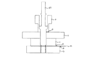
FIG. 11 is an example of a configuration diagram of a vibration wave motor using the vibrator in the first embodiment.
[0064]
When an AC voltage having a phase difference of π / 2 is applied to the piezoelectric element c from a power source (not shown), two bending vibrations are excited in two directions orthogonal to each other. As a result of this synthesis of vibration, a circular motion is formed on the upper end surface of the disk-like elastic body e with which the rotor g contacts, and the rotor g pressed against the wear-resistant disk-like elastic body e is friction-driven.
[0065]
d1 is a shaft, and a screw for sandwiching a vibrating body is provided at the lower portion, and a motor fixing member flange i and a screw for coupling are provided at the upper portion. A contact spring k is bonded to the outer periphery of the rotor body by bonding or the like to the rotor g, and a pressurizing coil spring j is attached to a spring case portion l formed on the inner periphery of the rotor body. An output gear h is fitted and coupled to the rotor g so as not to move relative to the radial direction. The coupling portion between the motor fixed body flange i and the gear h is constituted by a bearing. m is a flexible substrate for supplying power to the piezoelectric element.
[0066]
【The invention's effect】
As described above, according to the present invention, the difference between the natural frequencies of the two vibration systems is set, and the mechanical quality factor Q value of the higher natural frequency is set to be low, thereby making progress. It is possible to reduce the variation in the magnitude of the vibration wave at various portions of the drive unit that causes wave unevenness.
[Brief description of the drawings]
FIG. 1 is a frequency-admittance curve diagram of a vibrating body in a first embodiment of a vibration wave driving device according to the present invention. FIG. 2 is a vibration body in a first embodiment of a vibration wave driving device according to the present invention. Sectional view (a) and vibration mode diagram of vibrating body (b)
FIG. 3 is a diagram showing the piezoelectric element of FIG. 2. FIG. 4 is a cross-sectional view of a vibrating body in a second embodiment of the vibration wave driving device according to the present invention. The perspective view (a) of the vibrating body in 3rd Embodiment, and a piezoelectric element top view (b)
FIG. 6 is a configuration diagram of a power feeding member in a fourth embodiment of the vibration wave driving device according to the present invention. FIG. 7 is a configuration diagram of a power feeding member in the fifth embodiment of the vibration wave driving device according to the present invention. 8A and 8B are cross-sectional views of a vibrating body in a sixth embodiment of a vibration wave driving device according to the present invention. FIGS. 9A and 9B are shape diagrams of the metal member of FIG. ) (B) is a shape diagram of the groove of the first elastic body in the seventh embodiment of the vibration wave driving device according to the present invention. FIG. 11 is an eighth embodiment of the vibration wave driving device according to the present invention. FIG. 12 is a cross-sectional view of a conventional rod-shaped vibration wave motor. FIG. 13 (a) is a cross-sectional view of the vibration body of FIG. 12, and FIG. 12 (b) is its vibration mode diagram. Δf-amplitude unevenness curve of the vibrating body
a is the first elastic body n is the support plate
a2 is the third elastic body o is the hollow bolt
b is the second elastic body p is adhesive or rubber
c is electro-mechanical energy conversion element (piezoelectric element) q is bearing
d1 is shaft r is notched
d2 is nut s is metal member
e is disk-shaped elastic body t is electrode material
e2 is the second disk-shaped elastic body u is polyimide
f is
g is rotor 3B1 and 3B2 are B phase electrodes
h is
i is the flange
j is a coil spring
k is spring
l is spring case
m is flexible substrate
Claims (5)
前記2つの振動モードにおける前記振動体の固有振動数に差を設けるとともに、前記2つの振動モードのうち固有振動数の高い振動モードにおける前記振動体の機械的品質係数Q値を、固有振動数の低い振動モードにおける前記振動体の機械的品質係数Q値よりも低くしたことを特徴とする振動波駆動装置。Electro - mechanical energy conversion element two vibrations of vibration modes of the same shape is excited with a temporal phase difference to the drive portion of the elastic member by applying an AC voltage to, the synthesis of the vibration having a phase difference In a vibration wave driving device having a vibrating body that forms a circular or elliptical motion on the elastic body, and a moving body that is in pressure contact with the vibrating body ,
A difference is provided in the natural frequency of the vibrating body in the two vibration modes, and the mechanical quality factor Q value of the vibrating body in a vibration mode having a high natural frequency of the two vibration modes is expressed as a natural frequency. A vibration wave driving device characterized by being lower than a mechanical quality factor Q value of the vibrating body in a low vibration mode .
前記給電部材は、前記2つの振動モードの振動方向に関して、前記電極パターンまたは形状が互いに異なることを特徴とする請求項1または2に記載の振動波駆動装置。The vibrating member using a plurality of elastic members, the electro - and mechanical energy conversion element, the electro - a power supply member on which the electrode patterns for supplying power to mechanical energy conversion elements are formed to sandwich the fixed,
3. The vibration wave driving device according to claim 1 , wherein the power supply member has different electrode patterns or shapes from each other with respect to a vibration direction of the two vibration modes .
Priority Applications (1)
| Application Number | Priority Date | Filing Date | Title |
|---|---|---|---|
| JP2001355912A JP4095282B2 (en) | 2001-11-21 | 2001-11-21 | Vibration wave drive |
Applications Claiming Priority (1)
| Application Number | Priority Date | Filing Date | Title |
|---|---|---|---|
| JP2001355912A JP4095282B2 (en) | 2001-11-21 | 2001-11-21 | Vibration wave drive |
Publications (3)
| Publication Number | Publication Date |
|---|---|
| JP2003164171A JP2003164171A (en) | 2003-06-06 |
| JP2003164171A5 JP2003164171A5 (en) | 2005-06-30 |
| JP4095282B2 true JP4095282B2 (en) | 2008-06-04 |
Family
ID=19167532
Family Applications (1)
| Application Number | Title | Priority Date | Filing Date |
|---|---|---|---|
| JP2001355912A Expired - Fee Related JP4095282B2 (en) | 2001-11-21 | 2001-11-21 | Vibration wave drive |
Country Status (1)
| Country | Link |
|---|---|
| JP (1) | JP4095282B2 (en) |
Families Citing this family (5)
| Publication number | Priority date | Publication date | Assignee | Title |
|---|---|---|---|---|
| JP5074674B2 (en) | 2005-07-04 | 2012-11-14 | キヤノン株式会社 | Multilayer piezoelectric element and vibration wave motor |
| US9282001B2 (en) | 2007-03-05 | 2016-03-08 | Grid Net, Inc. | Policy based utility networking |
| JP6611446B2 (en) * | 2015-03-25 | 2019-11-27 | キヤノン株式会社 | Vibration type driving device and imaging device |
| JP6982228B2 (en) * | 2016-12-19 | 2021-12-17 | シンフォニアテクノロジー株式会社 | Spiral workpiece transfer device and parts feeder |
| JP6820474B2 (en) * | 2017-02-06 | 2021-01-27 | シンフォニアテクノロジー株式会社 | Work transfer device |
-
2001
- 2001-11-21 JP JP2001355912A patent/JP4095282B2/en not_active Expired - Fee Related
Also Published As
| Publication number | Publication date |
|---|---|
| JP2003164171A (en) | 2003-06-06 |
Similar Documents
| Publication | Publication Date | Title |
|---|---|---|
| US20050212385A1 (en) | Vibration element and vibration wave driving apparatus | |
| JP3823340B2 (en) | Vibration motor | |
| JPH05137355A (en) | Vibrating wave motor | |
| JP2003199376A (en) | Vibrating piece and vibration wave drive unit | |
| JP4435695B2 (en) | Piezoelectric motor operation method and piezoelectric motor in the form of a hollow cylindrical oscillator having a stator | |
| JP3526298B2 (en) | Vibrating body and vibration wave driving device | |
| JP4095282B2 (en) | Vibration wave drive | |
| US7825566B2 (en) | Ultrasonic actuator and method for manufacturing piezoelectric deformation portion used in the same | |
| JP4261894B2 (en) | Vibration type driving device | |
| US6198201B1 (en) | Vibration wave apparatus | |
| JP4026930B2 (en) | Vibration wave device and vibration wave drive device | |
| JP2001157473A (en) | Vibrator with electromechanical energy converter as vibration source, oscillating wave driver with vibrator as drive source, apparatus having oscillating wave driver and conveyor with vibrator as conveying source | |
| JPH06233557A (en) | Ultrasonic motor | |
| US9300228B2 (en) | Vibratory drive apparatus using lubricant between elastic member and piezoelectric member | |
| JPH02311184A (en) | Ultrasonic motor | |
| JP2003134858A (en) | Vibration wave drive unit | |
| JP3902955B2 (en) | Vibration body and vibration wave drive device | |
| JPH01177878A (en) | Oscillatory wave motor | |
| JP2000245175A (en) | Vibration actuator | |
| JP2005287246A (en) | Oscillator and oscillation wave motor | |
| JPH0681523B2 (en) | Vibration wave motor | |
| JP4350208B2 (en) | Vibration wave drive | |
| JP2001016875A (en) | Oscillatory wave drive device | |
| JPH07178370A (en) | Vibrator and vibrating actuator | |
| JP2004112924A (en) | Oscillatory wave drive unit |
Legal Events
| Date | Code | Title | Description |
|---|---|---|---|
| A521 | Written amendment |
Free format text: JAPANESE INTERMEDIATE CODE: A523 Effective date: 20041025 |
|
| A621 | Written request for application examination |
Free format text: JAPANESE INTERMEDIATE CODE: A621 Effective date: 20041025 |
|
| A977 | Report on retrieval |
Free format text: JAPANESE INTERMEDIATE CODE: A971007 Effective date: 20071107 |
|
| A131 | Notification of reasons for refusal |
Free format text: JAPANESE INTERMEDIATE CODE: A131 Effective date: 20071120 |
|
| A521 | Written amendment |
Free format text: JAPANESE INTERMEDIATE CODE: A523 Effective date: 20080121 |
|
| TRDD | Decision of grant or rejection written | ||
| A01 | Written decision to grant a patent or to grant a registration (utility model) |
Free format text: JAPANESE INTERMEDIATE CODE: A01 Effective date: 20080226 |
|
| A61 | First payment of annual fees (during grant procedure) |
Free format text: JAPANESE INTERMEDIATE CODE: A61 Effective date: 20080307 |
|
| FPAY | Renewal fee payment (event date is renewal date of database) |
Free format text: PAYMENT UNTIL: 20110314 Year of fee payment: 3 |
|
| R150 | Certificate of patent or registration of utility model |
Free format text: JAPANESE INTERMEDIATE CODE: R150 |
|
| FPAY | Renewal fee payment (event date is renewal date of database) |
Free format text: PAYMENT UNTIL: 20120314 Year of fee payment: 4 |
|
| FPAY | Renewal fee payment (event date is renewal date of database) |
Free format text: PAYMENT UNTIL: 20130314 Year of fee payment: 5 |
|
| FPAY | Renewal fee payment (event date is renewal date of database) |
Free format text: PAYMENT UNTIL: 20140314 Year of fee payment: 6 |
|
| LAPS | Cancellation because of no payment of annual fees |