CN1262481C - Device for recovering drinking water from condensate as well as a method and a deep-drawing die for production of said device - Google Patents
Device for recovering drinking water from condensate as well as a method and a deep-drawing die for production of said device Download PDFInfo
- Publication number
- CN1262481C CN1262481C CNB028222601A CN02822260A CN1262481C CN 1262481 C CN1262481 C CN 1262481C CN B028222601 A CNB028222601 A CN B028222601A CN 02822260 A CN02822260 A CN 02822260A CN 1262481 C CN1262481 C CN 1262481C
- Authority
- CN
- China
- Prior art keywords
- moulded piece
- extention
- deep
- zone
- mould
- Prior art date
- Legal status (The legal status is an assumption and is not a legal conclusion. Google has not performed a legal analysis and makes no representation as to the accuracy of the status listed.)
- Expired - Fee Related
Links
Images


Classifications
-
- C—CHEMISTRY; METALLURGY
- C02—TREATMENT OF WATER, WASTE WATER, SEWAGE, OR SLUDGE
- C02F—TREATMENT OF WATER, WASTE WATER, SEWAGE, OR SLUDGE
- C02F1/00—Treatment of water, waste water, or sewage
- C02F1/02—Treatment of water, waste water, or sewage by heating
- C02F1/04—Treatment of water, waste water, or sewage by heating by distillation or evaporation
- C02F1/14—Treatment of water, waste water, or sewage by heating by distillation or evaporation using solar energy
-
- B—PERFORMING OPERATIONS; TRANSPORTING
- B01—PHYSICAL OR CHEMICAL PROCESSES OR APPARATUS IN GENERAL
- B01D—SEPARATION
- B01D5/00—Condensation of vapours; Recovering volatile solvents by condensation
- B01D5/0057—Condensation of vapours; Recovering volatile solvents by condensation in combination with other processes
- B01D5/006—Condensation of vapours; Recovering volatile solvents by condensation in combination with other processes with evaporation or distillation
- B01D5/0066—Dome shaped condensation
-
- C—CHEMISTRY; METALLURGY
- C02—TREATMENT OF WATER, WASTE WATER, SEWAGE, OR SLUDGE
- C02F—TREATMENT OF WATER, WASTE WATER, SEWAGE, OR SLUDGE
- C02F2103/00—Nature of the water, waste water, sewage or sludge to be treated
- C02F2103/08—Seawater, e.g. for desalination
-
- Y—GENERAL TAGGING OF NEW TECHNOLOGICAL DEVELOPMENTS; GENERAL TAGGING OF CROSS-SECTIONAL TECHNOLOGIES SPANNING OVER SEVERAL SECTIONS OF THE IPC; TECHNICAL SUBJECTS COVERED BY FORMER USPC CROSS-REFERENCE ART COLLECTIONS [XRACs] AND DIGESTS
- Y02—TECHNOLOGIES OR APPLICATIONS FOR MITIGATION OR ADAPTATION AGAINST CLIMATE CHANGE
- Y02A—TECHNOLOGIES FOR ADAPTATION TO CLIMATE CHANGE
- Y02A20/00—Water conservation; Efficient water supply; Efficient water use
- Y02A20/124—Water desalination
- Y02A20/138—Water desalination using renewable energy
- Y02A20/142—Solar thermal; Photovoltaics
-
- Y—GENERAL TAGGING OF NEW TECHNOLOGICAL DEVELOPMENTS; GENERAL TAGGING OF CROSS-SECTIONAL TECHNOLOGIES SPANNING OVER SEVERAL SECTIONS OF THE IPC; TECHNICAL SUBJECTS COVERED BY FORMER USPC CROSS-REFERENCE ART COLLECTIONS [XRACs] AND DIGESTS
- Y02—TECHNOLOGIES OR APPLICATIONS FOR MITIGATION OR ADAPTATION AGAINST CLIMATE CHANGE
- Y02A—TECHNOLOGIES FOR ADAPTATION TO CLIMATE CHANGE
- Y02A20/00—Water conservation; Efficient water supply; Efficient water use
- Y02A20/20—Controlling water pollution; Waste water treatment
- Y02A20/208—Off-grid powered water treatment
- Y02A20/211—Solar-powered water purification
-
- Y—GENERAL TAGGING OF NEW TECHNOLOGICAL DEVELOPMENTS; GENERAL TAGGING OF CROSS-SECTIONAL TECHNOLOGIES SPANNING OVER SEVERAL SECTIONS OF THE IPC; TECHNICAL SUBJECTS COVERED BY FORMER USPC CROSS-REFERENCE ART COLLECTIONS [XRACs] AND DIGESTS
- Y02—TECHNOLOGIES OR APPLICATIONS FOR MITIGATION OR ADAPTATION AGAINST CLIMATE CHANGE
- Y02A—TECHNOLOGIES FOR ADAPTATION TO CLIMATE CHANGE
- Y02A20/00—Water conservation; Efficient water supply; Efficient water use
- Y02A20/20—Controlling water pollution; Waste water treatment
- Y02A20/208—Off-grid powered water treatment
- Y02A20/212—Solar-powered wastewater sewage treatment, e.g. spray evaporation
-
- Y—GENERAL TAGGING OF NEW TECHNOLOGICAL DEVELOPMENTS; GENERAL TAGGING OF CROSS-SECTIONAL TECHNOLOGIES SPANNING OVER SEVERAL SECTIONS OF THE IPC; TECHNICAL SUBJECTS COVERED BY FORMER USPC CROSS-REFERENCE ART COLLECTIONS [XRACs] AND DIGESTS
- Y02—TECHNOLOGIES OR APPLICATIONS FOR MITIGATION OR ADAPTATION AGAINST CLIMATE CHANGE
- Y02W—CLIMATE CHANGE MITIGATION TECHNOLOGIES RELATED TO WASTEWATER TREATMENT OR WASTE MANAGEMENT
- Y02W10/00—Technologies for wastewater treatment
- Y02W10/30—Wastewater or sewage treatment systems using renewable energies
- Y02W10/37—Wastewater or sewage treatment systems using renewable energies using solar energy
-
- Y—GENERAL TAGGING OF NEW TECHNOLOGICAL DEVELOPMENTS; GENERAL TAGGING OF CROSS-SECTIONAL TECHNOLOGIES SPANNING OVER SEVERAL SECTIONS OF THE IPC; TECHNICAL SUBJECTS COVERED BY FORMER USPC CROSS-REFERENCE ART COLLECTIONS [XRACs] AND DIGESTS
- Y10—TECHNICAL SUBJECTS COVERED BY FORMER USPC
- Y10S—TECHNICAL SUBJECTS COVERED BY FORMER USPC CROSS-REFERENCE ART COLLECTIONS [XRACs] AND DIGESTS
- Y10S203/00—Distillation: processes, separatory
- Y10S203/11—Batch distillation
-
- Y—GENERAL TAGGING OF NEW TECHNOLOGICAL DEVELOPMENTS; GENERAL TAGGING OF CROSS-SECTIONAL TECHNOLOGIES SPANNING OVER SEVERAL SECTIONS OF THE IPC; TECHNICAL SUBJECTS COVERED BY FORMER USPC CROSS-REFERENCE ART COLLECTIONS [XRACs] AND DIGESTS
- Y10—TECHNICAL SUBJECTS COVERED BY FORMER USPC
- Y10S—TECHNICAL SUBJECTS COVERED BY FORMER USPC CROSS-REFERENCE ART COLLECTIONS [XRACs] AND DIGESTS
- Y10S203/00—Distillation: processes, separatory
- Y10S203/23—Methanol
Abstract
The invention relates to a device for recovering drinking water from condensate, which is made up of a self-supporting moulded part (11) of a UV-resistant transparent plastic material, such as PET or PC. Said moulded part (11) has an open bottom surface (16) at the lower area thereof with a collecting groove (15), towards the exterior thereof, whereby said collecting groove (15) has an inside wall (18), which is orientated towards the outer surface (12) and serves at the same time as flotation aid and whereby said moulded part (11) has a pouring opening at the upper area (13) thereof. For the production of said device, a vacuum is generated in a particular deep-drawing die, not only in the region of the outer surface to be produced but also in the region of the collecting groove to be produced and said moulded part is separated from a distinct deep-drawing die piece outside of the collecting groove region.
Description
Technical field
The present invention relates to be used for reclaim the device of tap water, and make the method for this device and realize the deep-draw mould of this method from phlegma.
Background technology
The present invention especially comprises the occasion that is applicable to water, and is particularly marine, and is applicable to device on the bank, and it is phlegma that this device is used for evaporating under the influence of solar radiation water is assembled.In the general framework of this application that can expect, utilize sun power to carry out sea water desalinization and also can expect.
Removable inflatable desalination unit is well known owing to being used for marine emergency situation, this device comprises as the inflatable PVC ring of buoyancy aid and is positioned at independently conical transparent PVC thin slice on this buoyancy aid that this thin slice is as condensing surface.Phlegma accumulates between the inside of ring outside and taperer, because this thin slice taperer is also unstable dimensionally, thereby holds it in required shape by support bar.
The shortcoming that exists in this known device is that this thin slice damages easily, and is perforated especially easily.In addition, comprise that the structure of support bar bothers very much,, need assembling correctly for fear of fault.The manufacturing of single parts is relatively costly in this device, and because the flexibility of these thin slices, also has some shortcomings in the processing that this thin slice is cleaned.In addition, this thin slice can only bear limited mechanical load, and to outside weather condition, very responsive as wind and rain.At last, owing to this phlegma must be toppled over below this device, and may lose some phlegmas this moment, so the discharging of institute's accumulative phlegma is very inconvenient and existing problems.
United States Patent (USP) 3,415, disclosed a kind of folding device that water of condensation reclaims that is used in 719, this device utilizes sun power to carry out work, comprise inflatable transparent plastic body, be provided with in vivo can see through steam the gathering container as base member, be used to assemble phlegma, this device can be placed on the water body.Aforesaid drawbacks is also embodied on this device, particularly operation and dimensional stability aspect.
Disclosed a kind of device that water of condensation reclaims that is used in the document WO 00/03779, comprised a tapered cap, the lower end of this tapered cap has complete inside bending, assembles channel to form, and is used to hold the chassis that has evaporation unit.This evaporating pan is surrounded by other buoyancy ring.Except aforesaid drawbacks, this device that has the inflatable flotation ring is expensive to be made, the complex structure of evaporating pan and it is assembled into stand-by plant all need considers and formed further shortcoming.
Summary of the invention
Therefore the present invention is based on the problems referred to above provides a kind of device with aforementioned types of profiles, and the deep-draw mould of making method and this method of implementation of this device, this device has simple relatively structure, and can easily operate respectively and make, and have higher efficient with no problem ground.
According to the present invention, in order to address the above problem, the invention provides the device that is used for reclaiming tap water from phlegma, comprise
The hat self-supporting moulded piece of making by lucite PET or PC,
Described moulded piece comprises the open bottom area that is positioned at the bottom, and described open bottom area has the accumulation channel at the edge sidepiece,
Described moulded piece has pour spout on top.
The present invention also provides the manufacture method that is used for reclaiming from phlegma the device of tap water, comprises following operation steps:
(a) will have hot thin slice sealing member, thermoplastic lucite at edge side is placed on the edge side of deep-draw mould;
(b) in the zone of the circumferential surface that will form described moulded piece in described deep-draw mould and will form formation vacuum in the zone of building up channel;
(c) the described deep-draw mould of removing described moulded piece and being positioned at the zone that will form described accumulation channel from described mould; And
(d) with described moulded piece from separating at the extra-regional independent described deep-draw mould of described accumulation channel.
The present invention also provides the device that is used for reclaiming from phlegma tap water, and it is characterized in that: described device carries out deep-draw by the deep-draw mould and forms, and described deep-draw mould comprises:
Major portion wherein, is provided with cavity, is used to form the wall portion of hat moulded piece; And
Extention is used for forming described accumulation channel zone at the edge side of described moulded piece, and at least one described extention comprises aspirating hole, is used to form the accumulation channel of described moulded piece.
Preferably, the device that is used for reclaiming tap water of the present invention from phlegma, it is characterized in that: described pour spout is configured to the coaxial extension with respect to the central axis A-A of described moulded piece.
Preferably, the device that is used for reclaiming tap water of the present invention from phlegma, the described circumferential surface of described moulded piece outwards arches upward.
Preferably, the device that is used for reclaiming tap water of the present invention from phlegma, the angle of inclination of circumferential surface that wherein has the moulded piece of pyramid type or frustoconical is 30 °.
Because this device has structure of the present invention, all has certain advantage aspect making, use and utilizing.Hat thing, especially taper shape or conical butt or pyramidal moulded piece are formed as PET, PE, PP or PC by firm and material flexible.By this way, can obtain enough physical strengths and prevent the damage that causes by the object that has wedge angle.In addition, under the influence of wind-force, can not be out of shape yet.Therefore, functional integrity can't reduce like rain, wind etc. because of outside weather condition.
Because the geometrical shape of this moulded piece makes the present invention have favourable feature, that is, when this device was used on the water surface, phlegma was assembled the effect that channel has played buoyancy aid simultaneously.Therefore can omit other buoyancy aid or buoyancy ring.This device can be easily and is molded as complete parts continuously, therefore, can be with the low price manufacturing, this device especially conveniently is used for developing country.
This moulded piece does not comprise that the practical work of the bottom with evaporation section should take into account as further advantage.Therefore, this moulded piece can not cause the problem that algae and duricrust form.The cleaning of this device is simple and can come into operation immediately, and need not inflate and also do not need supporting structure.
According to another embodiment of the invention, pour spout is arranged on the top of moulded piece, is used for phlegma is poured out.By suitable placement, this pour spout can not polluted, and perhaps water can not flow out in undesirable mode yet.
According to preferred further embodiment of the present invention, this pour spout can be by screwed plug closes, therefore, feels can be used as bottle on intuitively.Simultaneously, after this device turned upside down, because the stability of this device on size design, this device also can be used as the container of assembling rainwater.
At last, be positioned at the top of moulded piece, particularly cone or pyramidal vertical another advantage that is preferably closed pour spout is that moulded piece as a whole must tilt 180 ° and pour out phlegma.That reclaims drinks the water yield even can increase easily by being present in condensing droplet on the inwall, that can pour out equally.
The further embodiment according to the present invention, molding process by being arranged on vertical each other two moulded piece, and wherein two moulded piece are suitable in bottom zone secured to one another.Therefore, obtained a so-called double-walled construction, this structure can obtain extra high efficient in the recovery of phlegma.This makes the inwall that any that can gather channel from the phlegma of outward flange drippage prematurely and outward flange extend in parallel, and can not drop onto the bottom zone of opening.The favourable aspect of another of the internal opening of projection is the infiltration that can suitably prevent the wave do not expected, and wherein this device swims on this wave.
When the inboard of the circumferential surface of apparatus of the present invention is provided with non-vaporific coating, and when the outside surface of this device can prevent to swipe, all embodiment of apparatus of the present invention can both show further advantage.
Except make simple, waste is seldom wherein only arranged in the mill, the setting of pilot hole is for unusual facility the device of being made up of two parts, particularly for the deep-draw mould, its pilot hole has two effects of lever and location or securing gear.Can be connected two moulded piece easily by caking agent or other coupling device with bacteriological protection and algae substances.
In all embodiment of apparatus of the present invention,, lauter tub can be inserted into the zone of pour spout in order to filter out silt, dust, bacterium etc.And/or be provided with the mineral substance bucket to increase mineral substance.When the hat surface, especially the cone surface supplies time-out a little, can obtain higher stability.Pour spout zone under flange is provided with porose, and this hole helps size stability, and can prevent from effectively by favourable mode to break.
In addition, according to another embodiment of the invention, in order to increase condenser zone and to obtain better cooling performance, the jut, particularly groove that outward flange can be by molding regions and/or formation or the form of fold and be increased.The effect of gathering heat in addition can obtain by the cloth that the material of the permeable steam of energy is made, and this cloth covers the downside of whole molding, and can prevent the pollution of wave wash simultaneously.In addition, be provided with other closed opening in the zone of assembling channel to be used for discharging.
In a word, by simple design, device of the present invention provides simply a kind of and operation intuitively, and the phlegma that has is assembled channel not only can provide suitable lever, but also helps floating.This device does not need to safeguard, can pile up, and just can come into operation immediately without any need for further annex or superstructure.
Because the shape of designed moulded piece, this molding can pile up safely and any problem can not occur, and simultaneously, what form like this piling up the support bar that stretches out by the pour spout from opening and very easily transport.
The manufacture method that is used for reclaiming from phlegma the device of tap water of the present invention includes special vacuum-treat, so that carry out the deep-draw operation by the sidepiece discharge outlet that is formed in the zone of assembling channel, and be used for moulded piece from assembling the extra-regional deep-draw mold separation of channel.Owing to be formed with special other discharge outlet in assembling the zone of channel, when independent deep-draw mould separated simply fully, according to required shape, the back joint portion that forms moulded piece easily was possible at the moulded piece of finishing.This method makes that the manufacturing of this device is extremely simple and efficient, especially has the device of rotational symmetry for those.
The deep-draw mould forms easily, comprise major portion and accessory constituent, this deep-draw mould is provided with in addition, be used for finishing the manufacture method that is used for reclaiming from phlegma the device of tap water provided by the invention, this deep-draw mould can molded avris has the gathering channel of constant wall thickness and constant outline.Thereby the back calmodulin binding domain CaM of moulded piece can be by molded well, otherwise the vacuum-treat in major portion zone will can not taken into full account.Be used to form the aspirating hole of assembling channel and preferably be arranged on the accessory constituent, and be connected on the extraction pipe of major portion.
According to further preferred embodiment, accessory constituent has peripheral rounded die edge, be used to form the inner edge of assembling channel, and accessory constituent preferably includes the plate washer that is used to isolate mould, and this plate washer is preferably formed the die edge in circle.
According to another embodiment of the invention, for the extraction pipe in the extention, the manufacturing of bleed plane and aspirating hole can be provided, this extention has and is divided into two-part structure.
Description of drawings
Hereinafter with reference to accompanying drawing, the present invention is carried out more detailed explanation, wherein:
Fig. 1 is the side isometric view according to first embodiment of device of the present invention;
Fig. 2 is 4 schematic representation of apparatus according to Fig. 1, and wherein these 4 devices pile up mutually in the top of each other;
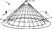
Fig. 3 shows an alternative embodiment of the invention, is used for the interpreter operation principle,
The schematic cross-section of Fig. 4 shows the situation of pouring out phlegma among the embodiment according to Fig. 3;
Fig. 5 is the view of another embodiment of device of the present invention, and wherein the black cloth of porous covers bottom zone, is used to prevent the flushing of wave, and is used to obtain bigger vaporization heat;
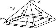
Fig. 6 is the synoptic diagram of further embodiment of the present invention;
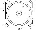
Fig. 7 is the upward view according to device shown in Figure 6;
Fig. 8 shows the synoptic diagram according to the assembling of device shown in Figure 6;
Fig. 9 to 12 shows each embodiment of the device with different geometries outer wall;
Figure 13 to 15 shows side isometric view, upward view and along the sectional view of Figure 13 center line XIII-XIII;
Figure 16 to 18 shows the various geometrical shapies of the gathering channel that is fit to pile up;
Figure 19 and 20 is synoptic diagram of manufacturing step of the embodiment of apparatus of the present invention;
Figure 21 shows the schematic sectional view that is used to make the embodiment of the deep-draw mould with rotational symmetry device of the present invention;
Figure 22 is that top left region is used for illustrating aspirating hole with the part sectioned view that certain proportion amplifies among Figure 21; And
Figure 23 to 27 shows the deep-draw mould of the application of the invention, makes each step of an embodiment of apparatus of the present invention.
Embodiment
Fig. 1 shows first embodiment that is used for reclaiming from phlegma the device of tap water of the present invention.Device 10 comprises the conical moulded piece 11 with circumferential surface 12, and this circumferential surface extends to bottom 14 from the top 13 of this moulded piece.This moulded piece 11 has rotational symmetry, and by transparent synthetic resins, forms as PET and PC.
In the bottom, intactly be formed at the edge sidepiece of moulded piece 11 to the gathering channel 15 of inner process, simultaneously, this gathering channel also is used to auxiliary floating.Assemble the bottom zone 16 of channel 15 around opening, the bottom zone of this opening forms by inwall 18 and the upper limb 17 of assembling channel 15.The inwall 18 and circumferential surface 12 approximate extensions abreast of assembling channel 15.
Be provided with relief outlet 19 in the bottom of assembling channel 15, be used for phlegma is all discharged, this relief outlet can seal by unshowned closure elements herein.Pour spout 20 is formed at the top 13 of moulded piece 11, and this pour spout comprises flange 21 and the threaded opening that is positioned at the outside, and this opening has the threaded lid 22 as closure elements.The molded formation between flange 21 and circumferential surface 12 of the whole formation portion 23 of other sidepiece, and the whole formation in top portion 23 ' is positioned on the lid, being used to increases the stability on top and is used to grasp handle, and can be used for other connection.In the simplest basic form according to device shown in Figure 1, this device only has a kind of structure of the form of piling up that roughly illustrates as Fig. 2, for the ease of transportation, after removing screwed lid 22, have very high spatial stability according to piling up of moulded piece shown in Figure 2 11, and make therefrom passing of support bar become possibility.
Fig. 2 and 3 is used for explaining in more detail the operation of an embodiment of apparatus of the present invention.With embodiment illustrated in fig. 1 different, this embodiment comprises the filter cylinder 24 in the zone that is positioned at pour spout 20, and the direction of inwall 18 towards the open bottom end zone of assembling channel extends to form peripheral protection edge 25, this protection edge is used for stopping salt and waste water, has roughly schematically illustrated this tilt state among Fig. 4.
As shown in Figure 3, this moulded piece 11 both can be placed on damp ground and also can be placed on the surface of water body.Under the influence of solar heat, the water in the open bottom end zone will evaporate, and water vapour is deposited on the internal surface of this circumferential surface 12 with the form of phlegma, and under the influence of gravity, flows to gathering channel 15 downwards along circumferential surface.When the phlegma in assembling channel 15 has accumulated to sufficient amount, catch this moulded piece 11 by the top 13 of moulded piece, and it is spun upside down, like this, make that accumulating in the water of assembling in the channel flows out by pour spout 20, wherein, has been taken away from moulded piece before the lid 22.By the oscillating motion of moulded piece, do not flow into the water of assembling the remaining phlegma in the channel 15 downwards and can be assembled easily and pour out yet.
In the embodiment shown in fig. 5, shown inwall has straight surface, and is different with the synoptic diagram of Fig. 3 and Fig. 1, and the bottom 14 of moulded piece opens up into the outside at the sidepiece at edge with suitable form, to be used to hold the additional unit of cloth.Label 26 expressions cover the black cloth on the open bottom end zone 16, and this cloth has water-permeable, and can be used to prevent the flushing of wave and obtain higher vaporization heat.
Fig. 6 and 7 is the schematic side elevation and the upward view of double-walled moulded piece 11 ', and as shown in Figure 8, this double-walled moulded piece comprises counterdie product 27 and last moulded piece 28.Last moulded piece equally forms the deep-draw element with the counterdie product, and comprises the conus portion of lower end squarish, and this conus portion is extending laterally.Counterdie product 27 has the chassis of squarish, is extruded with the complete moulded piece of a truncated cone at center chassis, and this complete moulded piece forms the inwall 18 of assembling channel 15.Just as shown in Figure 6, inwall 18 and outward flange 12 are almost near the top 13 that extends to moulded piece 11 ' abreast.In the operating process of this device, phlegma accumulate in relative broad, be formed in the gathering channel 15 between inwall 18 and the outward flange 12.Label 29 expressions are as the hole that grasps handle and be used for the continuous elongation of fastening this device.
According to shown in Figure 8, for the device shown in shop drawings 6 and 7, last moulded piece 28 is placed into counterdie product 27 central authorities, and bonding or fastening by appropriate locking latches, and pilot hole 29 aligns in two bottoms.This two moulded piece 27 and 28 also can be connected one to the other to together by fungi-proofing anti-algae tackiness agent or silicone respectively.
Fig. 9 to 12 shows the various geometrical shapies of the outer wall of moulded piece 11, and wherein the other Unitarily molded parts of this moulded piece are omitted in order to simplify all at this as flange, lever and relief outlet.According to Fig. 1, this device comprises conical moulded piece, and simultaneously according to Figure 10, circumferential surface is with the form of the hat thing outside of arching upward.The further like this stability that improved.According to structure shown in Figure 11 is another kind of possibility, and wherein circumferential surface has the shape similar in appearance to hemisphere.Pyramid structure according to the circumferential surface of Figure 12 provides regional peak use rate.
In Figure 13, schematically shown according to device shown in Figure 11, in order to increase circumferential surface and for better flowing downward of control phlegma drop, circumferential surface can increase by the zig-zag design that comprises groove.Also can adopt some other Unitarily molded director element to replace the above-mentioned groove that illustrates 30, this groove extends to bottom 14 from the top 13 of moulded piece 11.
Figure 14 shows the upward view according to device shown in Figure 13, and Figure 15 illustrates in general along the part sectioned view of the line XV-XV line among Figure 13 with the form of illustrating.
Figure 16 to 18 shows the various geometrical shapies that are used for the gathering channel that molding 11 reliably piles up with safety.In the bottom of circumferential surface 12, as shown in figure 16, be provided with peripheral molded 31, be used for taking in the part 32 of gathering channel 15 with relevant bending.
According to Figure 17, can guarantee that to side view this device can be stacked on accurate position in reliable mode according to the accommodation section of the similar mode of the embodiment of Fig. 5, be positioned on the upper end horizontal plane 34 of lower mould body because go up the lower surface 33 of molding this moment.
Figure 18 shows further embodiment, makes moulded piece 11 suitably pile up among this embodiment, and wherein inwall 18 extends in the mode parallel with circumferential surface 12, and supported as thin slice.
For the manufacturing according to device embodiment illustrated in fig. 5, Figure 19 and Figure 20 show suitable operation steps.Figure 19 is the synoptic diagram that does not have the bowl-type moulded piece of building up channel.Moulded piece 11 is provided with an opening portion 35, and this opening portion is coniform and is tapered downwards, and has the bottom part that is cut off subsequently.Just as shown in Figure 20, opening portion 35 rotates after heating or is upturned as inwall 18 subsequently.
Referring now to the embodiment of Figure 21 to 27 pair of deep-draw mould of the present invention and the manufacture method that is used for reclaiming the device of tap water from phlegma explain in more detail.Figure 21 shows the schematic sectional view of the deep-draw mould 32 with rotational symmetry, and this deep-draw mould comprises major portion 33 and extention 34.The chamber 35 of the wall portion that is used to form the hat moulded piece has been shown in major portion 33, molded (molded-in) zone 36 is as the pour spout of moulded piece, sidepiece tail pipe 37, the pumping chamber 38 that is provided with from the bottom of major portion 33 leads to extention 34, and peripheral seal member 39, the sealing part is set to the groove 40 of upside of the peripheral portion 41 of the upper end that is positioned at major portion 33.Edge section 41 extends to convex shoulder 42 places, and this convex shoulder comprises the bearing surface that is used for extention 34.Shown in Figure 19 and 20, line A-A indicate the respectively symmetry axis or the turning axle of the molding that forms.
Figure 22 is the more detailed amplification sectional view in the upper left quarter zone of deep-draw mould 32.Here, aspirating hole 43 to 45 can see especially clearly that these aspirating holes one are in the zone of the accumulation channel that forms in moulded piece.Here, aspirating hole 43 still is formed on the major portion 33, and directly leads in the annular bleed pipe 37, and simultaneously, pipe 44 and 45 leads to and be connected to extraction pipe 46 or pumping chamber 47 respectively.Because on the processing technology, extention 34 forms by main section 48 with at the lid shape ring part 49 of top closure pumping chamber 47 here.Main section 48 is provided with a die edge 50 that the periphery is rounded, and in the sectional view of Figure 22, this edge has the cross section of finger-shaped.Label 51 is illustrated in die edge and is used for peel of mould and molded plate washer (stop).This plate washer is used for after taking away from the conical funnel of mould or cavity 35 respectively moulded piece being separated from extention 34.The exterior contour of die edge 50 is circular, thereby in deep-draw operating period, under the situation of not drawing crack material, material as much as possible can be drawn in the internal space in the accumulation channel zone that will process on the moulded piece avris.
Method of the present invention is explained in more detail with reference to the synoptic diagram of Figure 23 to 27.According to zero position shown in Figure 23, in the first step operation, the hot thin slice 52 that thermoplastic lucite is made is placed on the deep-draw mould 32 that schematically illustrates, and has sealing member on the avris of this thin slice.Then, to form vacuum in the deep-draw mould 32 so that thin slice 52 moulding, according to Figure 24, thin slice 52 forms in deep-draw mould 32, then according to Figure 25, simultaneously, by the opening on the major portion 33 36 (Figure 21), and aspirating hole in the accumulation channel zone of the edge side by being formed at moulded piece and that be illustrated in Figure 22 43 is evacuated to 45.
According to Figure 26, then chilled moulded piece and extention 34 are removed from the major portion 33 of mould together, and in the end one go on foot, subsequently moulded piece is separated along plate washer 51, like this, the part 53 of moulded piece is provided on the one hand, the moulded piece of finishing 54 is provided on the other hand, these two portions all separate from extention 34.
Claims (39)
1. be used for reclaiming the device of tap water, comprise from phlegma
The hat self-supporting moulded piece of making by lucite PET or PC (11),
Described moulded piece (11) comprises the open bottom area (16) that is positioned at bottom (14), and described open bottom area has accumulation channel (15) at the edge sidepiece,
(13) have pour spout (20) to described moulded piece (11) on top.
2. device according to claim 1 is characterized in that: the described inwall (18) of described accumulation channel (15) has and the approximate part that extends in parallel of described conical circumferential surface (12).
3. device according to claim 1 and 2 is characterized in that: described accumulation channel (15) comprises the inwall (18) that has upper limb (17), and described open bottom end zone (16) forms by described inwall (18) and described upper limb (17).
4. device according to claim 1 is characterized in that: described pour spout (20) is configured to the coaxial extension of central axis A-A with respect to described moulded piece (11).
5. device according to claim 1 is characterized in that: described pour spout (20) is provided with removable lid (22).
6. device according to claim 5 is characterized in that: described lid (22) is processed into the lid with screw thread, and described lid with screw thread can be screwed into the screwed part on the described pour spout (20).
7. device according to claim 1 is characterized in that: form at least one moulding part (21,23,23 ') and be used to grasp and support.
8. device according to claim 7 is characterized in that: molded described holding part (21) is designed to flange.
9. device according to claim 1 is characterized in that: filter cylinder and/or mineral substance bucket (24) can be inserted into described pour spout (20).
10. device according to claim 1 is characterized in that: the angle of inclination of described circumferential surface (12) with described moulded piece (11) of pyramid type or frustoconical is 30 °.
11. device according to claim 1 is characterized in that: the described circumferential surface of described moulded piece (11) outwards arches upward.
12. device according to claim 1 is characterized in that: the inboard of described circumferential surface has the molded surface of expansion and/or molded director element (30), and they extend to bottom (13) from the top (14) of described moulded piece (11).
13. device according to claim 1 is characterized in that: described moulded piece body (11) is made up of two moulded piece (27,28), and described two moulded piece are fastening mutually in bottom zone separately.
14. device according to claim 13 is characterized in that: the described moulded piece (28) of going up has outward flange and chassis, and described counterdie product (27) has the inwall (18) of chassis and described channel simultaneously.
15. device according to claim 13 is characterized in that: be provided with pilot hole (29) at least one bottom.
16. device according to claim 14 is characterized in that: be provided with pilot hole (29) at least one bottom.
17. device according to claim 13 is characterized in that: the sidepiece towards the groove inwall of described straight bottom zone (16) is provided with non-vaporific coating.
18. device according to claim 14 is characterized in that: the sidepiece towards the groove inwall of described straight bottom zone (16) is provided with non-vaporific coating.
19. device according to claim 15 is characterized in that: the sidepiece towards the groove inwall of described straight bottom zone (16) is provided with non-vaporific coating.
20. device according to claim 1 is characterized in that: described open bottom end zone (16) is provided with coverture black, porous.
21., comprise following operation steps according to the manufacture method of the described device of claim 1:
(a) will have hot thin slice sealing member, thermoplastic lucite at edge side is placed on the edge side of deep-draw mould;
(b) in the zone of the circumferential surface that will form described moulded piece in described deep-draw mould and will form formation vacuum in the zone of building up channel;
(c) the described deep-draw mould of removing described moulded piece and being positioned at the zone that will form described accumulation channel from described mould; And
(d) with described moulded piece from separating at the extra-regional independent described deep-draw mould of described accumulation channel.
22. according to the described device of arbitrary claim among claim 1,2, the 4-20, it is characterized in that: described device carries out deep-draw by the deep-draw mould and forms, and described deep-draw mould comprises:
Major portion (33) wherein, is provided with the wall portion that cavity (35) is used to form the hat moulded piece; And extention (34), being used for forming described accumulation channel zone at the edge side of described moulded piece, at least one described extention (34) comprises aspirating hole (44,45), is used to form the described accumulation channel of described moulded piece.
23. device according to claim 22 is characterized in that: described cavity (35) has the molding regions that is used for pour spout.
24. device according to claim 22 is characterized in that: described extention (34) comprises at least one extraction pipe or pumping chamber (46,47), and described extraction pipe or pumping chamber are connected to described aspirating hole (44,45).
25. device according to claim 22 is characterized in that: described extention (34) comprises peripheral rounded die edge (50), is used for forming the edge of described accumulation channel.
26. device according to claim 24 is characterized in that: described extention (34) comprises peripheral rounded die edge (50), is used for forming the edge of described accumulation channel.
27. device according to claim 22 is characterized in that: described extention (34) comprises the plate washer (51) that is used for peel of mould.
28. device according to claim 24 is characterized in that: described extention (34) comprises the plate washer (51) that is used for peel of mould.
29. device according to claim 25 is characterized in that: described extention (34) comprises the plate washer (51) that is used for peel of mould.
30. device according to claim 27 is characterized in that: described plate washer (51) is gone up at the die edge (50) of described circle and is formed.
31. device according to claim 22 is characterized in that: described extention (34) has the structure that is formed by main section (48) and lid shape ring part (49) two portions (48,49).
32. device according to claim 24 is characterized in that: described extention (34) has the structure that is formed by main section (48) and lid shape ring part (49) two portions (48,49).
33. device according to claim 25 is characterized in that: described extention (34) has the structure that is formed by main section (48) and lid shape ring part (49) two portions (48,49).
34. device according to claim 26 is characterized in that: described extention (34) has the structure that is formed by main section (48) and lid shape ring part (49) two portions (48,49).
35. device according to claim 27 is characterized in that: described extention (34) has the structure that is formed by main section (48) and lid shape ring part (49) two portions (48,49).
36. device according to claim 28 is characterized in that: described extention (34) has the structure that is formed by main section (48) and lid shape ring part (49) two portions (48,49).
37. device according to claim 29 is characterized in that: described extention (34) has the structure that is formed by main section (48) and lid shape ring part (49) two portions (48,49).
38. device according to claim 30 is characterized in that: described extention (34) has the structure that is formed by main section (48) and lid shape ring part (49) two portions (48,49).
39. device according to claim 31 is characterized in that: described extention (34) has the structure that is formed by main section (48) and lid shape ring part (49) two portions (48,49).
Applications Claiming Priority (2)
| Application Number | Priority Date | Filing Date | Title |
|---|---|---|---|
| DE10155080A DE10155080A1 (en) | 2001-11-09 | 2001-11-09 | Device for drinking water from condensate |
| DE10155080.4 | 2001-11-09 |
Publications (2)
| Publication Number | Publication Date |
|---|---|
| CN1592719A CN1592719A (en) | 2005-03-09 |
| CN1262481C true CN1262481C (en) | 2006-07-05 |
Family
ID=7705188
Family Applications (1)
| Application Number | Title | Priority Date | Filing Date |
|---|---|---|---|
| CNB028222601A Expired - Fee Related CN1262481C (en) | 2001-11-09 | 2002-11-07 | Device for recovering drinking water from condensate as well as a method and a deep-drawing die for production of said device |
Country Status (15)
| Country | Link |
|---|---|
| US (1) | US7534327B2 (en) |
| EP (1) | EP1448481B1 (en) |
| JP (1) | JP2005507778A (en) |
| KR (1) | KR20040055801A (en) |
| CN (1) | CN1262481C (en) |
| AT (1) | ATE317371T1 (en) |
| AU (1) | AU2002337185B2 (en) |
| BR (1) | BR0214014A (en) |
| CA (1) | CA2466673A1 (en) |
| DE (2) | DE10155080A1 (en) |
| ES (1) | ES2261738T3 (en) |
| IL (1) | IL161806A0 (en) |
| MX (1) | MXPA04004421A (en) |
| WO (1) | WO2003040040A2 (en) |
| ZA (1) | ZA200404202B (en) |
Families Citing this family (18)
| Publication number | Priority date | Publication date | Assignee | Title |
|---|---|---|---|---|
| DE102004063447B4 (en) * | 2004-12-30 | 2009-09-10 | Hartmann + Hartmann Industriedesign U. Werbeagentur Gmbh | Device for the recovery of fresh water |
| PT2230894E (en) * | 2007-12-18 | 2013-10-17 | Holding P M M Hoff B V | Device and method for recovering moisture present in the atmosphere |
| DE202008006240U1 (en) * | 2008-05-07 | 2008-10-16 | Tashlyk, Oleksandr | Water purification method |
| AT507782B1 (en) | 2009-01-26 | 2010-08-15 | 4Elementsoe Invent Gmbh | PORTABLE, SOLAR THERMAL DEVICE FOR PRODUCING FRESH WATER FROM WASTE WATER OR SALTWATER |
| DE102009006668A1 (en) | 2009-01-29 | 2010-08-05 | Technische Universität Bergakademie Freiberg | Process and apparatus for solar evaporation of salt solutions |
| DE102009032665A1 (en) | 2009-07-09 | 2011-01-13 | Gfi-Innovationstechnologie Gmbh | Device for drinking water production |
| GB2472034A (en) * | 2009-07-22 | 2011-01-26 | Questor Group Ltd C | Solar desalination system |
| DE102009034844A1 (en) | 2009-07-27 | 2011-02-03 | Hans-Josef Friedrich | Specifically molded system for obtaining drinking water from condensate, comprises molded parts produced from complete or self-supporting transparent material with an inner collecting groove for the condensate |
| DE102009035858A1 (en) | 2009-07-31 | 2011-02-03 | Strauß, Maximilian Thomas | Mobile device, which is mounted as domed housing on heatable container, for the distillation of raw water, comprises raw water supply pipeline guided to outer side of housing from bottom to top, and upwardly opened collecting groove |
| DE102010007517A1 (en) | 2010-02-11 | 2011-08-11 | Friedrich, Hans-Josef, 84069 | Drinking water producing system, has channel collecting condensate produced during evaporation of fluid, where fluid is fragmented into water vapor and residual components by using sun, such that condensate is collected in channel |
| WO2012055431A1 (en) | 2010-10-26 | 2012-05-03 | Roland De Vicq | Sunoven and method for constructing such a sunoven |
| US9102546B2 (en) * | 2011-09-20 | 2015-08-11 | Saudi Arabian Oil Company | Apparatus for distillation of water and methods for using same |
| DE102013012948B4 (en) | 2013-07-29 | 2015-08-06 | Rudolf Krause | Mobile device for obtaining steam-distilled ultrapure water, which has an electrical conductivity below 1.0 μS |
| CN104141327B (en) * | 2014-07-23 | 2015-09-30 | 中国人民解放军第三军医大学军事预防医学院 | Sampler in the sand bed of a kind of desert |
| US10814245B2 (en) * | 2014-08-26 | 2020-10-27 | Saeed Alhassan Alkhazraji | Solar still apparatus |
| CN104353253B (en) * | 2014-11-28 | 2015-11-18 | 龚柱 | The strip preparing concentrate converges the method for designing of bar |
| KR200483566Y1 (en) * | 2015-06-02 | 2017-05-30 | 대한민국 | dewdrop collector and pot having the same |
| DE202016000867U1 (en) * | 2016-02-10 | 2017-05-11 | Henning Doyen | Condensate floating construction |
Family Cites Families (14)
| Publication number | Priority date | Publication date | Assignee | Title |
|---|---|---|---|---|
| US2865138A (en) * | 1958-12-23 | Water recovery unit and method | ||
| US2848389A (en) * | 1955-07-21 | 1958-08-19 | Bjorksten Johan | Water purifier |
| US3290230A (en) * | 1961-08-09 | 1966-12-06 | Nippon Electric Co | Solar still apparatus for extracting and collecting water from soil |
| US3336206A (en) * | 1962-10-24 | 1967-08-15 | Nippon Electric Co | Water collecting apparatus having a synthetic resin roof treated with an oxidizing agent |
| US3973602A (en) * | 1970-01-13 | 1976-08-10 | Kruse Frederick W | Funnel with signal |
| US3932080A (en) * | 1972-02-15 | 1976-01-13 | Showa Denko Kabushiki Kaisha | Apparatus for manufacture of tubular film from thermoplastic resin |
| US4036209A (en) * | 1975-06-26 | 1977-07-19 | Press Jack J | Atmospheric heat exchange method and apparatus |
| DE3015254A1 (en) | 1980-04-21 | 1981-10-22 | Kraftwerk Union AG, 4330 Mülheim | Solar heat powered desalination system - with inverted siphons joining transparent dome to condensate tank and sea-water supply |
| US4495034A (en) * | 1980-06-05 | 1985-01-22 | Frank Lucas | Waste effluent treatment and solvent recovery system |
| GB2166965B (en) | 1984-11-19 | 1988-08-10 | Minoru Sakamoto | Distillation apparatus and cooling attachment therefore |
| US4966655A (en) * | 1987-01-05 | 1990-10-30 | Wilkerson Jr William M | Plastic covered solar still |
| DE3820744A1 (en) * | 1988-06-18 | 1989-12-21 | Walter Ziegler | Apparatus for producing and utilising condensed water |
| FI106296B (en) * | 1998-11-09 | 2001-01-15 | Amsco Europ Inc Suomen Sivulii | Method and apparatus for treating water for evaporation |
| BR0107674A (en) * | 2000-01-17 | 2002-09-24 | Akzo Nobel Nv | Installation for condensing water from an aqueous liquid using a temperature gradient, device suitable for use in it, process for condensing water from an aqueous liquid using a temperature gradient, evaporation compartment hollow closed preferably seamlessly, and use of a copolyether amide |
-
2001
- 2001-11-09 DE DE10155080A patent/DE10155080A1/en not_active Withdrawn
-
2002
- 2002-11-07 BR BR0214014A patent/BR0214014A/en not_active Application Discontinuation
- 2002-11-07 US US10/493,373 patent/US7534327B2/en not_active Expired - Fee Related
- 2002-11-07 AU AU2002337185A patent/AU2002337185B2/en not_active Ceased
- 2002-11-07 CN CNB028222601A patent/CN1262481C/en not_active Expired - Fee Related
- 2002-11-07 KR KR10-2004-7007026A patent/KR20040055801A/en not_active Application Discontinuation
- 2002-11-07 EP EP02772409A patent/EP1448481B1/en not_active Expired - Lifetime
- 2002-11-07 AT AT02772409T patent/ATE317371T1/en not_active IP Right Cessation
- 2002-11-07 ES ES02772409T patent/ES2261738T3/en not_active Expired - Lifetime
- 2002-11-07 MX MXPA04004421A patent/MXPA04004421A/en active IP Right Grant
- 2002-11-07 WO PCT/EP2002/012441 patent/WO2003040040A2/en active IP Right Grant
- 2002-11-07 JP JP2003542093A patent/JP2005507778A/en not_active Withdrawn
- 2002-11-07 IL IL16180602A patent/IL161806A0/en unknown
- 2002-11-07 CA CA 2466673 patent/CA2466673A1/en not_active Abandoned
- 2002-11-07 DE DE50205802T patent/DE50205802D1/en not_active Expired - Lifetime
-
2004
- 2004-05-28 ZA ZA2004/04202A patent/ZA200404202B/en unknown
Also Published As
| Publication number | Publication date |
|---|---|
| BR0214014A (en) | 2004-10-13 |
| MXPA04004421A (en) | 2005-05-16 |
| WO2003040040A2 (en) | 2003-05-15 |
| DE50205802D1 (en) | 2006-04-20 |
| ES2261738T3 (en) | 2006-11-16 |
| WO2003040040A3 (en) | 2003-12-24 |
| IL161806A0 (en) | 2005-11-20 |
| CA2466673A1 (en) | 2003-05-15 |
| EP1448481A2 (en) | 2004-08-25 |
| CN1592719A (en) | 2005-03-09 |
| DE10155080A1 (en) | 2003-05-22 |
| AU2002337185B2 (en) | 2008-06-19 |
| US7534327B2 (en) | 2009-05-19 |
| KR20040055801A (en) | 2004-06-26 |
| EP1448481B1 (en) | 2006-02-08 |
| ATE317371T1 (en) | 2006-02-15 |
| ZA200404202B (en) | 2005-09-28 |
| JP2005507778A (en) | 2005-03-24 |
| US20050098423A1 (en) | 2005-05-12 |
Similar Documents
| Publication | Publication Date | Title |
|---|---|---|
| CN1262481C (en) | Device for recovering drinking water from condensate as well as a method and a deep-drawing die for production of said device | |
| CN1170990C (en) | Apparatus for collecting material floating on a body of water | |
| CN108350686B (en) | Method and device for collecting water | |
| JP2003506212A (en) | Water still having pervaporation membrane and method of operating the same | |
| CN205917830U (en) | Green building rain water circulation filtration device | |
| US6406619B1 (en) | Three stage sewage treatment plant | |
| CN1278312A (en) | Method and apparatus for separating floating pollutants | |
| OA11702A (en) | Solar water still. | |
| CN1205130C (en) | Coagulator | |
| JP3211250U (en) | Rainwater storage device | |
| CN2345265Y (en) | Sewage purifier | |
| US20210039018A1 (en) | Oil and aqueous phase separator | |
| CN112791465B (en) | Active sand filter | |
| CN113047410A (en) | Prefabricated pump station of sewage filth autosegregation | |
| JP6391559B2 (en) | Float collection device | |
| CN113123403A (en) | Intelligent rainwater storage well lid and implementation method thereof | |
| CN105780848A (en) | Rain and snow water collection apparatus | |
| CN214571120U (en) | Water pollution filtering and purifying device | |
| RU187399U1 (en) | Camping water purifier | |
| RU26056U1 (en) | DEVICE FOR CAPTURING FROM THE WATER RESERVOIR OF FLOATING HOLLOW ASH MICROSPHERES | |
| CN212789890U (en) | Novel pipe chute mud-water separation device | |
| CN215592647U (en) | Industrial wastewater surface oil film separator | |
| CN215479900U (en) | Novel landfill leachate nanofiltration concentrated solution treatment system | |
| RU2225475C1 (en) | Technique to collect floating hollow ash microspheres from surface of water basin and device for its implementation | |
| CN209685549U (en) | A kind of novel sludge concentration tank |
Legal Events
| Date | Code | Title | Description |
|---|---|---|---|
| C06 | Publication | ||
| PB01 | Publication | ||
| C10 | Entry into substantive examination | ||
| SE01 | Entry into force of request for substantive examination | ||
| C14 | Grant of patent or utility model | ||
| GR01 | Patent grant | ||
| CF01 | Termination of patent right due to non-payment of annual fee |
Granted publication date: 20060705 Termination date: 20151107 |
|
| EXPY | Termination of patent right or utility model |