CN1256073C - Teeth cleaning device - Google Patents
Teeth cleaning device Download PDFInfo
- Publication number
- CN1256073C CN1256073C CNB028009975A CN02800997A CN1256073C CN 1256073 C CN1256073 C CN 1256073C CN B028009975 A CNB028009975 A CN B028009975A CN 02800997 A CN02800997 A CN 02800997A CN 1256073 C CN1256073 C CN 1256073C
- Authority
- CN
- China
- Prior art keywords
- handle portion
- function element
- brush part
- data
- coil
- Prior art date
- Legal status (The legal status is an assumption and is not a legal conclusion. Google has not performed a legal analysis and makes no representation as to the accuracy of the status listed.)
- Expired - Fee Related
Links
- 238000004140 cleaning Methods 0.000 title claims abstract description 64
- 230000008878 coupling Effects 0.000 claims abstract description 27
- 238000010168 coupling process Methods 0.000 claims abstract description 27
- 238000005859 coupling reaction Methods 0.000 claims abstract description 27
- 230000005540 biological transmission Effects 0.000 claims abstract description 18
- 230000006870 function Effects 0.000 claims description 121
- 230000007246 mechanism Effects 0.000 claims description 28
- 238000004804 winding Methods 0.000 claims description 10
- 230000000694 effects Effects 0.000 claims description 9
- 230000033001 locomotion Effects 0.000 claims description 9
- 230000001939 inductive effect Effects 0.000 claims description 8
- 238000004458 analytical method Methods 0.000 claims description 7
- 238000013500 data storage Methods 0.000 claims description 7
- 230000009351 contact transmission Effects 0.000 claims description 5
- 230000002401 inhibitory effect Effects 0.000 description 31
- 238000000034 method Methods 0.000 description 12
- 230000008901 benefit Effects 0.000 description 9
- 238000001514 detection method Methods 0.000 description 9
- 229910000859 α-Fe Inorganic materials 0.000 description 8
- 238000006243 chemical reaction Methods 0.000 description 7
- 238000003860 storage Methods 0.000 description 7
- 230000002349 favourable effect Effects 0.000 description 6
- 230000014509 gene expression Effects 0.000 description 6
- 230000005611 electricity Effects 0.000 description 5
- 238000012546 transfer Methods 0.000 description 5
- 239000003990 capacitor Substances 0.000 description 4
- 238000013461 design Methods 0.000 description 4
- 230000001976 improved effect Effects 0.000 description 4
- 229920003023 plastic Polymers 0.000 description 4
- 238000005201 scrubbing Methods 0.000 description 4
- 230000008859 change Effects 0.000 description 3
- 238000010586 diagram Methods 0.000 description 3
- 238000004519 manufacturing process Methods 0.000 description 3
- 230000004044 response Effects 0.000 description 3
- XAGFODPZIPBFFR-UHFFFAOYSA-N aluminium Chemical compound [Al] XAGFODPZIPBFFR-UHFFFAOYSA-N 0.000 description 2
- 229910052782 aluminium Inorganic materials 0.000 description 2
- 230000001680 brushing effect Effects 0.000 description 2
- 239000003795 chemical substances by application Substances 0.000 description 2
- 230000003749 cleanliness Effects 0.000 description 2
- 238000005516 engineering process Methods 0.000 description 2
- 238000009434 installation Methods 0.000 description 2
- 238000012423 maintenance Methods 0.000 description 2
- 239000000463 material Substances 0.000 description 2
- 238000005259 measurement Methods 0.000 description 2
- 230000004048 modification Effects 0.000 description 2
- 238000012986 modification Methods 0.000 description 2
- 230000010355 oscillation Effects 0.000 description 2
- 230000010363 phase shift Effects 0.000 description 2
- 238000009958 sewing Methods 0.000 description 2
- GOLXNESZZPUPJE-UHFFFAOYSA-N spiromesifen Chemical compound CC1=CC(C)=CC(C)=C1C(C(O1)=O)=C(OC(=O)CC(C)(C)C)C11CCCC1 GOLXNESZZPUPJE-UHFFFAOYSA-N 0.000 description 2
- 239000000126 substance Substances 0.000 description 2
- 102100039398 C-X-C motif chemokine 2 Human genes 0.000 description 1
- 241001269238 Data Species 0.000 description 1
- 241000628997 Flos Species 0.000 description 1
- 101000889128 Homo sapiens C-X-C motif chemokine 2 Proteins 0.000 description 1
- 206010022998 Irritability Diseases 0.000 description 1
- SNIOPGDIGTZGOP-UHFFFAOYSA-N Nitroglycerin Chemical compound [O-][N+](=O)OCC(O[N+]([O-])=O)CO[N+]([O-])=O SNIOPGDIGTZGOP-UHFFFAOYSA-N 0.000 description 1
- 235000014676 Phragmites communis Nutrition 0.000 description 1
- 230000003213 activating effect Effects 0.000 description 1
- 230000004913 activation Effects 0.000 description 1
- 230000006978 adaptation Effects 0.000 description 1
- 238000013459 approach Methods 0.000 description 1
- 230000000712 assembly Effects 0.000 description 1
- 238000000429 assembly Methods 0.000 description 1
- 239000011230 binding agent Substances 0.000 description 1
- 238000004891 communication Methods 0.000 description 1
- 230000000295 complement effect Effects 0.000 description 1
- 230000009849 deactivation Effects 0.000 description 1
- 230000005684 electric field Effects 0.000 description 1
- 230000005672 electromagnetic field Effects 0.000 description 1
- 238000005538 encapsulation Methods 0.000 description 1
- 230000005284 excitation Effects 0.000 description 1
- 239000011888 foil Substances 0.000 description 1
- 230000006698 induction Effects 0.000 description 1
- 230000001788 irregular Effects 0.000 description 1
- 230000005389 magnetism Effects 0.000 description 1
- 230000004899 motility Effects 0.000 description 1
- 230000003287 optical effect Effects 0.000 description 1
- 230000002085 persistent effect Effects 0.000 description 1
- 238000003825 pressing Methods 0.000 description 1
- 230000008569 process Effects 0.000 description 1
- 230000001105 regulatory effect Effects 0.000 description 1
- 238000007789 sealing Methods 0.000 description 1
- 239000004575 stone Substances 0.000 description 1
- 125000000391 vinyl group Chemical group [H]C([*])=C([H])[H] 0.000 description 1
- 229920002554 vinyl polymer Polymers 0.000 description 1
- 238000004078 waterproofing Methods 0.000 description 1
Images


Classifications
-
- A—HUMAN NECESSITIES
- A61—MEDICAL OR VETERINARY SCIENCE; HYGIENE
- A61C—DENTISTRY; APPARATUS OR METHODS FOR ORAL OR DENTAL HYGIENE
- A61C17/00—Devices for cleaning, polishing, rinsing or drying teeth, teeth cavities or prostheses; Saliva removers; Dental appliances for receiving spittle
- A61C17/16—Power-driven cleaning or polishing devices
- A61C17/22—Power-driven cleaning or polishing devices with brushes, cushions, cups, or the like
- A61C17/221—Control arrangements therefor
-
- A—HUMAN NECESSITIES
- A61—MEDICAL OR VETERINARY SCIENCE; HYGIENE
- A61C—DENTISTRY; APPARATUS OR METHODS FOR ORAL OR DENTAL HYGIENE
- A61C17/00—Devices for cleaning, polishing, rinsing or drying teeth, teeth cavities or prostheses; Saliva removers; Dental appliances for receiving spittle
- A61C17/16—Power-driven cleaning or polishing devices
- A61C17/22—Power-driven cleaning or polishing devices with brushes, cushions, cups, or the like
- A61C17/222—Brush body details, e.g. the shape thereof or connection to handle
Abstract
The invention relates to a handle (10) of an electric teeth cleaning device comprising a coupling element (30) for mechanically coupling a brush (20), a drive (22) for the brush (20) and a control function (18) for the drive (22), said control function (18) comprising an operation locking function (36), which can be activated and deactivated by a release function (38), in particular of the brush (20). The handle (10) has a read function (44) and a coil (46) as a coupling function for the contactless transmission and reading of single or multiple data of the release function (38). The operation locking function (36) is activated or deactivated in accordance with an output signal of the read function (44).
Description
Technical field
The present invention relates to a kind of electronic device for cleaning teeth.The present invention be more particularly directed to the handle portion of this tooth-cleaning device, this handle portion has the connecting device that is used to connect various or different brush parts, is used to drive the driving mechanism of the brush part of corresponding connection, and control device.The invention still further relates to brush part, particularly the toothbrush adnexa of this handle portion.
Background technology
Scrub or the device of cleaning teeth for example the dentilave device of electric toothbrush or electricity have handle or handle portion or handle usually, various burnishers are the toothbrush adnexa for example, nozzle, tooth inner face toothbrush or brush part can be connected with this handle, handle or handle, like this, make some user can use oneself tooth-cleaning device, particularly with the burnisher of individual relating to persons.This electric toothbrush is known, for example, and referring to DE 19627752 A1 or EP 0624079 B1.
By DE 299 15 858 U1, known a kind of tooth-cleaning device, wherein each different toothbrush only can insert in the appointment jack in the pillar.So just started and be the program of this specific toothbrush design.Yet the fact shows that particularly the child is difficult to find each opening and the plug engage of inserting individual toothbrush.And because it need be provided with some different jacks, each toothbrush has corresponding itself the different plug of jack, so the pillar manufacturing is very complicated.
At United States Patent (USP) 5,184, in 959 in disclosed another device,, therefore, can be each toothbrush by shell and specify separately the time signal of scrubbing for each handle toothbrush is specified himself holding tank in the enclosure.This structure is well-designed from the viewpoint of making, but the particular data that it does not provide detection and storage user to operate about cleaning of teeth.
This tooth-cleaning device can improve in many aspects.The special problem that runs in battery-driven toothbrush is that accumulator can exhaust prematurely.For example, this can occur in situation about suitably not keeping well under the occasions such as travelling, thereby driving mechanism is unexpectedly opened.And it can also occur in handle portion not always when correctly the toothbrush adnexa is connected, like this, because handle portion lacks the compatibility, for example, the coupling part particularly may be damaged at drive area, perhaps, can not guarantee to realize suitable cleaning function owing to lack the compatibility.
And, tooth-cleaning device is that electric toothbrush comprises handle portion and attachable brush part, wherein handle portion has a switch that mechanically starts at the recess of its shell, this switch is according to circumstances covered by the waterproofing protection paillon foil, like this, when brush part was connected with handle portion, the stretching, extension of the cabinet by brush part drove the switch contact of described switch, this tooth-cleaning device about 1992 by Bausch ﹠amp; Lomb company puts goods on the market in the U.S. with the model Interplak (registered trade mark) of for example PB-6.In case the brush part that connects has started switch contact, just can be by the driving mechanism of " opening " switch connection toothbrush on the handle.May be that reason for safety provides these features because do not resemble the handle portion in many other electric toothbrushes, the driving shaft in the above-mentioned toothbrush on the direction of longitudinal axis before and after swing.The stroke of axle is very big, so that the connection switch has the danger that causes personnel to injure during the brush part that not have to connect on handle portion, because driving shaft carries out the reciprocating motion of the sewing needle on the similar sewing machine.The independent claims relevant with handle portion and brush part are completely different by the prior art.
Referring to DE 28 26 008 C2, it discloses a kind of switch that is used to activate electric toothbrush, and it has the permanent magnet that is arranged on the annular actuated components, and described annular actuated components can be arranged on the shell with moving axially.The permanent magnet conducting of annular driver part or discharge the magnetosensitive switch, reed switch relay for example, described magnetosensitive switch arrangement is in the inside of the shell of toothbrush.The annular actuated components can be folded down from the toothbrush shell, and shell and driver part are cleaned after unloading it easily.Unload actuated components and have the effect that the electric toothbrush of making can not start equally, like this, thereby prevent demolition the toothbrush of actuated components when transportation, start unexpected consume battery or accumulator voluntarily.
Yet, provide the above-mentioned feature of touring safety function to a certain degree in fact also unsuccessful, because under the Interplak scheme, need very big power make brush part be connected or break away from, to promote to be arranged on the switch contact in the handle portion with handle portion.Another problem is that switch contact is dirty, and need pay the cover cap that very big strength is made the anti-dirty or waterproof on the switch contact.But the demolition switch ring in the patent specification of DE 28 26 008 C2 wishes to play safety effect equally in travelling, but the switch ring under the demolition is easily lost and is become problem, particularly on the road, if so, even under the situation that battery or accumulator are full of, can not allow handle work.And, these are known to provide safe method almost not show the motility relevant with other comfortable function on the road, for example the running parameter of handle portion is to specific brush part self adaptation, perhaps specific collection and storage clean data or the analog of user.
Toothbrush and the manufacture method thereof used from the known a kind of DIY of EP 0 848 921 A1, wherein as the label of data storage be fastened on inseparably toothbrush originally on one's body, promptly between bristle carrier and cup-shaped retaining element.Like this, attempt utilizes tag storage to number, be connected diameter with safety criterion, maximal rate, country of origin, producer's trade mark, goods, the data relevant with for example bar code, and this bar code is read by the electronics reading system at the cashier place in DIY shop.Label can be made by aluminum or heat resistant plastic material especially, because toothbrush is under the higher temperature in use.This label obviously is aluminum or vinyl disc, and it has the surface that loads optical readable information, and is connected inseparably with brush body.Yet the shortcoming of this sign indicating number is that it has very little memory capacity, and can not programme again.But its readability is also supposed the form free access of sign indicating number with light, and this is not suitable for various application.
In addition, known have a multiple electronic article security system, and the safety label comprising for example electronic resonance circuit or soft magnetism sensor strip is fixed on the article, and by the electric field excitation on the door that is installed in the shop exit region.If article are not handed over money, just safety label still when active state, detects signal and sends warning.For example at Physikalische Blatter 57 (2001), the 5th volume, can find relevant details in the article of Gieselher Herzer " Der gro β eLauschangriff auf Ladendiebe " by 43 to 48 pages.
A kind of subsystem of these systems is called RFID (radio frequency identification) system, is applied in the contactless chip card, recently, be applied in motor vehicles lock or the receipt cabinet, under latter event, be used for according to cabinet whether empty send invoice.
These systems are known in, for example United States Patent (USP) 5812065, WO 00/42584, United States Patent (USP) 6177870, WO 00/39768, DE 199 53 651 A1 or WO 98/24527, disclosed system is used for electronic toy in the image that is equipped with transponder be equipped with swap data between the main frame of reader in the description of in the end mentioning.
Summary of the invention
An object of the present invention is to provide a kind of improved handle portion and improved brush part thereof of electronic device for cleaning teeth, it can overcome the shortcoming of prior art, develops and additional advantage is provided.Particularly, the purpose of this invention is to provide a kind of comfortable safety device, it can start other specific function and/or prevent the incorrect use of tooth-cleaning device.
The handle portion of electronic device for cleaning teeth comprises: be used for the connecting device of mechanical connection brush part, the driving mechanism of brush part, control function element with driving mechanism, described control function element comprises the work prohibiting function element that can be started or be stopped by the function element of energizing of brush part particularly, described purpose is implemented in and is that fundamentally handle portion comprises read functions element and coil, be used as the one or more of of non-contact transmission and information that reads the function of energizing or data, the output signal of response read functions element is started or hold function.The advantage of these aspect ratio prior aries is can operate them when handle portion is connected with brush part with breaking away from comfily when being connected, no longer need set up parts separately and set up separately to get and start/stop the prohibiting function element, for other the function that makes things convenient for user lays the first stone by mechanically activating toothbrush portion in handle portion.And, there is no need switching mechanism or other element to be pulled down from handle portion for realization safe functioning in travelling, please note that electronic handle portion, brush part or the analog of buying the tooth device of following term may not only refer to electric toothbrush, but also refer to other electric tooth-cleaning device, dentilave device for example, tooth inner face cleaner or analog, wherein, handle portion is used for being connected with cleaning part, described cleaning part or use, or disposable unit by specific user.In this scope, term brush part, toothbrush adnexa, plug-in type toothbrush, standby toothbrush and term cleaning part, nozzle, the equivalence of tooth inner face cleaner can be exchanged in other words.
According to one embodiment of present invention, advantageously, read out function element and/or linkage function element can be by the particularly turn-on power loss element startups of driving mechanism of turn-on power loss element of handle portion.
As long as brush part and handle portion mechanical connection, read out function element or linkage function element transmission and sense data also are easily.
In this respect, it is favourable providing the function that is coupled of Irritability ground operation.
Coil preferably is arranged near in the handle portion part that is coupled device, perhaps also can be in the zone that is coupled device itself.
The one or several circles of coil around or around the longitudinal axis of handle portion, preferably the rotation axis of the driving shaft of the drive mechanism in the handle portion also is favourable.
Can also make the rotating shaft of the winding region of coil and handle portion or longitudinal axis form angle between about 140 ° and about 40 °, preferably form the angle between 90 ° ± 10 °.
Under the situation of exception, it also is favourable that the function of energizing will be got in touch with handle portion itself, particularly is fastened in the shell of handle portion or on it.
And, by driving mechanism, might set driving shaft when rotating shaft carries out alternative at least rotatablely moving, perhaps when rotating shaft is rotated motion, and/or carry out the backswing campaign around being substantially perpendicular to the gyroaxis that rotating shaft arranges.
Advantageously, the read out function element, control function element and work prohibiting function element are the parts of ASIC (application-specific IC).Yet under some applicable cases, it also is favourable that these function element are embodied as discrete function, perhaps, as possible, just implements by the appropriate software in microcontroller or the analog.
For achieving the above object, brush part has the drivable head toothbrushes and the device that is connected, to comprise the work prohibiting function element of handle portion, driving mechanism and the electric toothbrush of connecting device with mechanical connection, the function of energizing that is used for starting or stoping prohibiting function in conjunction with brush part is characterised in that, the function of energizing of brush part comprises contactless data carrier and coil, plays the effect that is coupled of one of non-contact transmission or multinomial data.
The data medium of brush part or be coupled function element preferably the turn-on power loss element by handle portion or the turn-on power loss element related with it start, be preferably used in the connection driving mechanism.
As long as brush part and handle portion mechanical connection, data medium or linkage function element just transmit data.
It is favourable that sense is coupled function element capablely.
Coil preferably is arranged on the part of connecting device of cooperation, on the part of the brush part that perhaps is adjacent.
Coil have one or more circles around or around the longitudinal axis of brush part, the rotation axis of the axle of perhaps pegging graft in the brush part.
Rotation axis of the winding region of coil and brush part or longitudinal axis form the angle between about 140 ° and about 40 °, preferably 90 ° ± 10 °.
Preferably be associated therewith, be arranged on the brush part at special-shaped sleeve, described sleeve is contained in the tubular handle of brush part, read/transfer function element or part or the arrangements of components of carrying out this function element be connected on special-shaped sleeve or with it.And the handle of brush part also can hold the axle of pegging graft.
Contactless data carrier is configured to transponder, does not preferably have the passive transponder of self power supply.
Be provided with the transponder of data storage, preferably have the memory capacity in about 100 bit to 104 bit range with numerical data.
The invention still further relates to a kind of electronic device for cleaning teeth, it has handle portion and the brush part of the aforementioned type that interrelates.In this device, the data of transmitting between brush part and handle portion not only can comprise and are used to start the data of function of energizing, and can comprise specific data about each brush part, described particular data comprises operating parameter when being used for operate toothbrush part or handle portion, or comprises specific user's operating parameter especially.
Advantageously, numerical data is subjected to coding/control.
Further propose one or more data item and transmit to handle portion from brush part, otherwise and/or.
According to another embodiment of the invention, energy suitably transmits to brush part from handle portion, so that start passive transponder.
Preferably propose handle portion and brush part by coil inductance couple, be used for swap data or transmission data and/or transmission of power.
The advantage of system of the present invention and advantageous embodiments thereof are being summarized as follows earlier:
On the handle portion of electronic device for cleaning teeth, advantageously be provided with control device, described control device has the work inhibiting apparatus, and this work inhibiting apparatus can stop via non-contact data exchange or transfer of data by the function element of energizing on the burnisher.The former finger of such burnisher has the function element of energizing, be used for stopping by the exchange of the non-contact data between brush part and the handle portion or transfer of data the inhibiting apparatus of handle portion.Like this, these features provide the protection that prevents the tooth-cleaning device accidental switch.Burnisher in the compatibility that the function element of energizing is provided is connected with handle portion, and the prohibiting function element of handle portion can be connected the driving mechanism of handle portion when stopping thus.Under the situation or analogue of travelling, fall burnisher by folding from handle portion and can avoid unexpected connection at an easy rate.Like this, the accumulator of driver can not unexpectedly be consumed too early.For example there is no need on the switch of handle portion additional design or mechanical treatment to implement to connect locking.Advantageously can propose, particularly only when burnisher correctly is connected with handle portion, have only starting drive can stop inhibiting apparatus by burnisher.This can followingly realize: promptly the starting drive on the burnisher and the checkout gear on the starting drive on handle portion structure and adjust make have only starting drive with respect to checkout gear and even handle portion preferably predetermined towards and/or the position, the described device of energizing is only effectively.For prevent owing to plug unaccommodated toothbrush adnexa damage handle portion particularly actuating device or its be coupled and be damaged, the device of energizing can have additional coding or transmit this coded data, can distinguish burnisher by described coded data.Like this, handle portion has coding/checkout gear or separates the encoding function element, to the code detection of the burnisher of corresponding connection or separate coding.When only occurring correct coding and producing into corresponding signal, can stop inhibiting apparatus.Thereby handle portion detects each burnisher that this moment connects, and energizing according to the burnisher control driving mechanism that detects.Usually can be at predetermined interval inquiry coding.In a certain embodiments of the present invention, only when the handle portion ON of for example electric driver mechanism is switch activated, just start coding/checkout gear.This has the advantage of the current loss minimum of needed electronic component.In order to connect tooth-cleaning device, the on and off switch of user start-up control device or electro-motor as normally.Yet electro-motor or driving mechanism are not directly started by driving switch, but at first start coding and/or checkout gear, then, as long as the compatible toothbrush adnexa with suitable coding is connected with handle portion, just can start the motor of handle portion.Therefore, final, start coding and/or checkout gear with on and off switch, just start the driving mechanism of handle portion indirectly, in other words, the element of energizing that needs only brush part just can start when stopping the inhibiting apparatus of handle portion.If do not have brush part to be connected or engage with handle portion, if perhaps on handle portion, there is incompatible brush part, when the switch of starting handle part, coding and/or checkout gear will can not detect correct coding, the element of energizing that perhaps the toothbrush adnexa is provided with, this can not stop the inhibiting apparatus of handle portion, therefore, in this case, the handle portion of the toothbrush of electrical motor driven just can not carry out work.Starting one of coding and/or advantage that checkout gear brought by on and off switch is, preferably only just need be for coding and/or checkout gear supply electric current when the switch connection of handle portion or when disconnecting otherwise coding and/or checkout gear are inoperative or do not have the seedbed and work.Whether certainly, also might start coding and/or checkout gear with regular or irregular interval at the toothbrush duration of work, exist compatiblely to detect, promptly the toothbrush adnexa of correct coding also can be handled when disconnecting or disconnect like this.This preferably might correct the wrong detection to the toothbrush adnexa.If reason whatsoever, handle portion is connected by device, and brush part do not connect (having started switch), for example since interim electric fault or strong jamming field disconnect but start once more the next time of handle portion use device.When the cleaning of teeth EO, if start the driving mechanism of on and off switch once more with the disengagement lever part, this driving mechanism will directly be stopped by current the startup, if can use, remove the effect of inhibiting apparatus, therefore, when then connecting the on and off switch of handle portion once more, just can repeat described step.And coding and/or checkout gear are configured to work in the noncontact mode.Its advantage is to have avoided being folded down the dirty or wearing and tearing of the contact surface that causes and bringing interference owing to frequently loading onto.Handle portion also might comprise from the burnisher received encoded signal or stop the signal receiver of the signal of inhibiting apparatus.Handle portion also can be equipped with the signal projector that sends visit or enabling signal to the function element of energizing of burnisher, and the latter is started on energy, and feeds back to coded signal or enabling signal.Can be with passing through corresponding active or passive signal transmitter or suitable activation member, coded signal that the function element of energizing of replacement burnisher is carried out or enabling signal emission.
The coding of the element of energizing of burnisher or structure can pass through for example to adopt in the part of burnisher itself or burnisher or parts or in the device in correspondence to be implemented in the colour circle or the shaped rings of type described in the WO99/20202, and the content of the disclosure is incorporated herein by reference.
Further method comprises provides electronic checkout gear, is used to detect the electronic code of the element existence of energizing of pointing out the corresponding burnisher that connects.Burnisher sends the signal of telecommunication of not encoding or encoding to handle portion, to the signal receiver expressing information that passes thereon, thereby makes it corresponding burnisher.Handle portion is also possible, and described signal is also fed back subsequently by the burnisher coding earlier to burnisher transmission calling-on signal, and this calling-on signal is by burnisher coding or modification.Can also be provided with transmitting device or wireless device by each burnisher that connects of Electromagnetic Wave Detection.Particularly, can connect transponder to burnisher.Electromagnetic wave takes place earlier in handle portion, provides energy to general passive transponder.The transponder stored energy, and the detector in handle portion feeds back individual ID, described detector detects ID and correspondingly distinguishes burnisher and stop the prohibiting function element.
Like this, burnisher is characterised in that code device or the such element of energizing that magnetic, electricity and/or Electromagnetically-operating are provided.
Another feature can comprise provides signal receiver, with from the tooth-cleaning device received signal; And signal projector, to send encoded signals to tooth-cleaning device; Be preferably between signal receiver and the signal projector and insert code device, with signal coding receiving.The code device or the element of energizing preferably are configured to the suitable individual components of pulling down or replacing from the remainder of burnisher.Thus obtained advantage is burnisher, can be only with a form of implementation manufacturing.By the independently code device or the function element of energizing are installed, burnisher can be encoded based on individual character, and distributes to the handle portion of particular type.Yet when only requiring the touring safety function element to be provided or to detect incompatible burnisher, the code device of the element that is configured to energize can also be integrated in the burnisher.The code device or the element of energizing preferably are arranged in the zone of connection between burnisher and the handle portion or joint.What be convenient to like this encode reads, and detects the element of energizing by the recognition device on the handle portion.Particularly, the function element of energizing or code device can be integrated in the ring, and described ring is arranged in the end near the burnisher of handle portion, particularly pass through tight fit with it, and the buckle interlock thereon.The different structure of recognition device can provide separately or combination provides.On burnisher, can adopt the heteroid code device or the element of energizing.
Avoid unexpected except the protection handle portion and open and use improperly the incompatible burnisher, the coding of burnisher and can advantageously be used to carry out more function the detection of its handle portion.In this regard, can utilize handle portion to assign to control one or preferably some functions of tooth-cleaning device according to detected corresponding burnisher.Suppose that each user of handle portion has the burnisher of self, the detected coding of the burnisher of the tooth-cleaning device by the current use of the person of consulting and using, the control device of handle portion can automatically be set.Do not need user to tell current user to tooth-cleaning device by pressing button and analog.The operating parameter of device automatically adapts to each user.This produces maximum ease of use.Particularly, control device can be regulated operating parameter, and cleaning frequency for example is during cleaning speed and the cleaning or threshold value or apply the pressure limit of recommendation from the corresponding user that trend has been distinguished.Can be provided with and store various user personalities, when beginning to clean, behind the coding and definite corresponding user of the burnisher that has detected current use, use one of described user personality by control device.For this reason, coding and/or checkout gear send a corresponding signal to control device, when using electric toothbrush, for example, can reduce the operating speed of motor speed from the adult when the child person of being to use, thereby the child is used soft clean operation.In addition, but the signal that control device response coding and/or checkout gear send and changing is determined the persistent period of intervalometer according to discerning user, for example is set at 2 minutes for child's intervalometer, and for the adult, intervalometer is set at 3 minutes.Buzzer by selecting to be fit to child's tone and being fit to the adult can also change the timer signal type.Another scheme that itself provides is to be new intervalometer tune storage data in the toothbrush adnexa, and these data are transferred to handle portion from the toothbrush adnexa, also can take the circumstances into consideration to store at this handle portion.
Can also store and handle and pointing out for example automatic applied pressure of corresponding signal that sends of the interval during cleaning frequency, cleaning speed, the cleaning, between the cleaning or response detection device of specific user data in the display device.This also causes the user comfortableness to improve.
Therefore, by burnisher or its coding of consulting and using, handle portion detects, and that is to say, discerns corresponding user.Also can carry out specific function element control according to the particular type of the burnisher that uses.For example, when use has particular characteristic, for example, during the toothbrush adnexa of high or low hardness, the operating parameter of handle portion can change automatically.Equally, when dissimilar burnishers surfaces cleaning implement in the tooth for example, the gum-massaging instrument, or tongue cleaner can move another operation sequence when being connected with handle portion.Can respond the individual and/or with the removable burnisher of individual relating to persons, suitably allocate the cleaning time of speed, suggestion, actuation movement, cleaning frequency, cleaning speed, the threshold value etc. of exerting pressure.
And, by identification personal cleanliness or scrubbing tool or clear and definite substitute, and, for example, particularly the time of using in the past, might accurately determine its state of wear by measuring the historical data of this specific burnisher.When use had the burnisher of chemical addition agent, can discern definite its service life by the build date that comprises on coding.Also cleaning that can be indicating predetermined or maintenance shop every.
According to a preferred embodiment, in the handle portion of toothbrush, be provided with RFID (radio frequency identification) sensing device, to implement to energize function, sensing device refers to being arranged on the data detection device of the transponder in the brush part, and described data are transmitted in the noncontact mode.RFID sensing device and transponder or other contactless data carrier of part all have one separately and are coupled element, this can be a coil, also can be microwave antenna for example, therefore, data, clock pulses or energy be by being coupled the element exchange between these sensing devices and the contactless data carrier.Like this, by the sensing device that is also referred to as transceiver (emitter/receiver), might receive data or information from transponder.On the contrary, also might use sensing device in transponder, to write data.Like this, for example, exist and write the transponder data relevant with the user of individual brush part, or with cleaning during relevant data or be used for the probability of individual brush part, therefore, after during user uses through certain maximum cleaning, can remind user to change this brush part with new brush part.Usually, when transponder was passive, energy was transferred to transponder from sensing device, this means that transponder self does not have power supply.
Like this, to the transponder transmission of power, be used to start transponder from sensing device.Using under the situation of active transponder, mean that transponder itself has power supply, for example with minicell as battery etc., it will be appreciated, of course, that and nonessential transmission of power deactivation transponder.Preferably, under the stable condition, electronic device for cleaning teeth is provided with inductive and is coupled in other words that magnetic is coupled, and is coupled element as sensing device and transponder noncontact.In pertinent literature, this being coupled is called as inductive wireless system or inductive couplings short range devices.Under given applicable cases, operating frequency is preferably 13.56MHz.Transponder itself constitutes 1 bit or many bits transponder.Information transmitted or data are preferably carried out by the load modulation in the transponder between transponder and sensing device, for this reason, on one-period frequency or certain spike train, be switched on or switched off the load resistance in transponder, like this, in sensing device, form reaction or feedback by inductive couplings, thereby make data be transferred to sensing device from transponder, vice versa.
Put it briefly, basic thought of the present invention is expressed as follows, this also is the literal expression of claims independent claims: energize element or the function element of energizing of be used in the burnisher to quit work inhibiting apparatus or function can constitute with the simple embodiment of coding and/or checkout gear or function element, this coding and/or checkout gear or function element in the following way: the existence that promptly only can detect the replacement toothbrush in the handle portion is (1 bit information) whether.For this reason, for example, functional component can be arranged in the toothbrush, this is corresponding to the reaction part in the handle portion, be under the connection status at burnisher and handle portion, reaction part receives a preferred digital signal from functional component, and for example set inhibiting apparatus is stopped, thereby, can start handle portion and burnisher mechanism by driving mechanism.This provides the function of the simple touring safety of handle portion, when burnisher is not connected as mentioned above with its functional component, prevents handle portion work.Therefore, burnisher being thrown off connection from handle portion is exactly to start the touring safety function.And the step of interrupting the on and off switch of handle portion for example or any other device there is no need.This also helps to arrange this functional component in burnisher, under connection status, this functional component is corresponding or get in touch with the reaction part in the handle portion, the work of the handle portion of the burnisher that makes it to prevent that leukorrhagia stopping is incompatible is not because manufacturer can be installed to incompatible burnisher on the functional component that can get in touch with the reaction part of handle portion usually.This can eliminate mechanical problem and the danger of using incompatible toothbrush adnexa to bring.This represents coding and/or the checkout gear or the function of simple form, and this is the simplest relatively structure, and allows only to determine whether burnisher is connected with handle portion, perhaps the burnisher that is connected with handle portion compatibility whether.
Situation for exception can also propose functional component and typically be located in the burnisher, for example, for the end user provides transponder etc. or code device, as the stand-alone component that can independently handle, perhaps be located at handle portion originally on one's body.This method can be used for, the end user has held the handle portion of outfit work inhibiting apparatus, but have and do not possess the element of energizing or the functional component domestic are scrubbed or during burnisher, the described element of energizing is used to make the prohibiting function element of handle portion or handle to stop.In order to ensure using these, although it is compatible with the handle machinery that upgrades, but also not having the inhibiting apparatus that is suitable for being arranged in the handle portion communicates by letter, and make the typical older replaceable burnisher of its element of energizing that stops, thereby, significant method is for but element or functional component or the transponder parts as independent process of energizing are offered the end user, for the situation of these exceptions, is provided with clamp device and is used for the fastening element of energizing on handle portion.This makes, for example, the end user can directly be fastened on this energize element or functional component on the handle portion or handle that is equipped with inhibiting apparatus, outside as at the regional inside and outside shell of the reaction part of handle portion, by originally on one's body rather than on burnisher, arrange functional component at handle portion, under specific or exceptional case, stop effect to the inhibiting apparatus of handle portion.As a result, handle portion also can be operated with the compatible burnisher of machinery that also is not equipped with the functional component of energizing function element or communicating by letter with inhibiting apparatus.This scheme it is also contemplated that ought be for example because cost, be not that all cooperate the burnisher with the replacing of compatibility all will be equipped with this element of energizing, code device or functional component with handle portion or handle machinery.It will be appreciated, of course, that by the user scheme that element is fastened on handle portion of directly will energizing be a kind of exceptional case, usually, the element of energizing should be arranged on brush part or the cleaning part.
Moreover coding/checkout gear can also be configured so that and start being coupled of burnisher, can allow burnisher to have several possible difference (many bit informations).Although coding and/or checkout gear or function element such as initial description are merely able to the result that for example is/denys, promptly, the result whether compatible burnisher is connected with handle portion, a kind of coding of modification and/or checkout gear or function element but can make it to carry out touring safety function other function in addition for example by two, four or six different codings of identification burnisher.Like this, for example, it is that the toothbrush (hard bristle) of adult design still be the toothbrush of designed for children (soft bristle) that handle portion might be discerned what be connected with handle portion, whether uses tooth inner face cleaner replacement toothbrush, also can distinguish between other parameter.When feasible, the coding of respective detection can be used for driving control device selectively, is used to carry out driving mechanism, the control actuating speed, such as during the cleaning of speed or recommendation or the like.Yet, have in coding or coding and/or checkout gear or function element under the situation of probability of several (between about 2 to 10) difference, also personal cleanliness's instrument and countless commercially available burnisher all can not be picked out.Owing to the limited probability of these difference, might distinguish burnisher (child's toothbrush, the Toothbrush for adult of particular type at most, tooth inner face toothbrush, dental floss, each all constitutes the adnexa of handle portion), and between several other cleanings or Cleaning tool, find difference.
When hope detects the discrete burnisher that every kind of being made by manufacturer is fit to be connected with the handle portion of compatibility with coding and/or checkout gear or function element, just exist scope from about 10
6To about 10
12Between difference (many bit informations) probability, for this reason, typically use transponder or similar electronic installation.In this case, provide by manufacturer and the identification of each burnisher of being connected with handle portion is possible.Except the aforementioned probability of relevant simple encoding scheme, this also provides and has passed through the tools for measurement account of the history prerequisite of the ability of the degree of wear of definite burnisher more accurately.When use had the replaceable burnisher of chemical addition agent, the build date of indicating in coding makes can distinguish service life, can indicate and follow the predetermined cleaning interval or the maintenance interval of burnisher in other words.
No matter how simple and complicated the coding of burnisher and coding and/or checkout gear or function element has, by compatible especially burnisher and handle portion are broken away from, thereby prevent handle portion work, it is perfectly safe that the function element of energizing of the prohibiting function element on the handle portion is guaranteed in the touring safety function.Utilize any one in these encoding schemes, what no matter adopt is 1 bit or many bit scheme, as long as burnisher does not have coding or is not equipped with the function element of energizing in primary importance, can prevent to start handle portion equally.Do not have coding or not have outfit to energize the burnisher of function element when being connected when this with handle portion, be arranged in the reaction part in the handle portion, emitter, receptor or similarly sensing device can not with the functional component that is not arranged in the incompatible burnisher, receptor, emitter, transponder or similar device communication, therefore, though as situation compatible at burnisher but that be not connected with handle portion, in handle portion, do not identify the incompatible burnisher of existence, thereby, can not start handle portion owing to do not have the element of energizing to be provided with to stop the probability of inhibiting apparatus effect.
Basically, in the handle portion of electronic device for cleaning teeth, in the simple embodiment of the coding of burnisher or coding and/or checkout gear or function element, need only notice guaranteeing that coding in handle portion and/or checkout gear or function element can discern suitable promptly compatible burnisher and whether be connected with handle portion.If this suitable promptly compatible burnisher is not connected with handle portion, just can not start handle portion, because burnisher is not fit to stop to be positioned at the relevant element of energizing of the inhibiting apparatus of handle portion.On the contrary, when the burnisher of the compatibility that is equipped with energize function element or suitable coding is connected with handle portion, there are the suitable coding or the element of energizing if detect with checkout gear in the handle portion, be not later than the startup of the on and off switch in handle portion, just stop the effect of inhibiting apparatus, carry out work thereby can start handle portion, thereby, the driving mechanism by shank portion promote cleaning end for example the head toothbrushes of burnisher carry out work.
This respect, the invention still further relates to the method for electronic device for cleaning teeth of operation or tooth brushing device, described electronic device for cleaning teeth or tooth brushing device comprise handle portion and the burnisher that is suitable for being attached thereto or engaging, for example toothbrush adnexa or analog, handle portion is in connection status with burnisher and communicates by letter, or transmit or swap data in the noncontact mode, perhaps in handle portion, be provided with and detect burnisher and whether be connected, and/or whether the burnisher that is connected with handle portion is the burnisher device with the handle portion compatibility with handle portion.When not having burnisher to be connected, drive with the described information switch connection starting handle electricity partly that no thoroughfare is arranged in the handle portion with handle portion.This can realize by the work inhibiting apparatus in handle portion.Therefore, when burnisher is not connected with handle portion or engages, can not start handle portion, thereby, comfortable touring safety function is provided.Another of this method is characterised in that burnisher comprises the function element of energizing, the described checkout gear of function element in being arranged in handle portion of energizing signals, the notice burnisher is connected with handle portion, thereby stop the work of inhibiting apparatus, therefore, can start the work of cleaning of teeth adnexa by connecting electric drive.Yet, if burnisher is not equipped with this element of energizing, even be in connection status following time at burnisher and handle portion, the driving of handle portion can not start, because in burnisher, be provided with described energizing during element, will think to relate to burnisher and handle portion is incompatible.
Other embodiment of this method also comprises specific individual, on specific burnisher or the similar basis different cleaning instrument is connected the step that handle portion is encoded, thereby, not only to provide burnisher or compatible burnisher to be in to connect or the information of connection status not by corresponding codes/checkout gear to handle portion or handle, and to provide use burnisher type or use the individual's of burnisher information, in this case, therefore, the data of individual and/or specific burnisher can be set or be stored as to handle portion corresponding parameters or operating parameter.In the scope of description, each method is explained in detail, and belonged to method of the present invention as basic feature of the present invention to device.
Description of drawings
With reference to the accompanying drawings and in conjunction with following detailed description, can know other purpose, advantage, feature and application possibility of the present invention to embodiment.Be appreciated that describe and/or illustrated any feature, no matter use separately or, all constitute theme of the present invention, no matter the general introduction in claims or background technology part is how to be used in combination in all senses.
In the accompanying drawings,
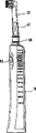
Fig. 1 is the perspective view with handle portion and electric toothbrush of the toothbrush adnexa that can be attached thereto;
Fig. 2 is the longitudinal profile sketch map of handle portion of the electric toothbrush of Fig. 1, expresses shell and is arranged in the CD-ROM drive motor with actuating device and driving shaft in the shell, the accumulator of CD-ROM drive motor and the charging assembly of accumulator;
Fig. 3 is the sketch map according to the electric toothbrush with toothbrush adnexa of another preferred embodiment of the present invention, this toothbrush adnexa have gummed thereon or integrated wherein transponder and corresponding checkout gear be used in handle portion non-contact transmission data;
Fig. 4 is the perspective view of the toothbrush of Fig. 3;
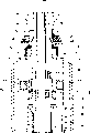
Fig. 5 is the auspicious figure in cross section of the toothbrush of similar Fig. 3 and 4, the structure of the transponder chip in the coding collar of the end that is arranged on the toothbrush adnexa is shown, with transmitting coil and receiving coil and relevant electrometric determination device in handle portion, toothbrush adnexa and handle portion are shown in and are connection status;
Fig. 6 is the perspective illustration that embodiment of handle portion of the present invention removes shell;
Fig. 7 is the perspective illustration that shell is removed in the front portion of another embodiment of handle portion;
Fig. 8 is the longitudinal sectional drawing of another embodiment of link of an embodiment of handle portion;
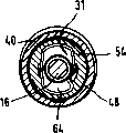
Fig. 9 is the viewgraph of cross-section of the handle portion of Fig. 7, and section roughly is arranged in the longitudinal axis that is substantially perpendicular to driving shaft or the coil region of rotation axis;
Figure 10 is the partial view of an embodiment of toothbrush adnexa, is depicted as handle wall partly cut-away in special-shaped sleeve zone;
Figure 11 is the longitudinal sectional view of the toothbrush adnexa of Figure 10;
Figure 12 is the viewgraph of cross-section of toothbrush adnexa in coil region of Figure 10, and section is arranged to basically perpendicular to longitudinal axis or rotating shaft;
Figure 13 is the special-shaped telescopic perspective illustration that the grafting axle of transponder and coil that is mounted thereon and adjacency is shown;
Figure 14 A is the perspective view with shaped rings of transponder and coil, shown in partly extract out from the shank portion of toothbrush adnexa;
Figure 14 B is the toothbrush annex map that illustrates around the coil of handle or pipe winding;
Figure 15 is the shaped rings with transponder and coil, and the side view of the grafting axle part of toothbrush adnexa;
Figure 16 is the view of the about an angle of 90 degrees of arrangement rotation of Figure 15;
Figure 17 is the cross sectional view that about 180 degree angles are rotated in the arrangement of Figure 15;
Figure 18 is the view of similar Fig. 5, and the improved structure of expression coil is provided with the coefficient of coup that ferrite improves coil; And
Figure 19 is a sketch map of representing control device with the form of block diagram, to explain the principle of described structure, this control device has reading device, electronic analysis device and as the work inhibiting apparatus of handle portion element, with transponder as the element of toothbrush adnexa, handle portion and toothbrush adnexa machinery electromagnetic ground and/or magnetically be coupled inductive.
The specific embodiment
Electric toothbrush shown in the drawings has the handle portion 10 of the closed shell 26 of band, and described shell 26 also accommodates electro-motor known in the field 22 except holding other element as shown in Figure 2; Power supply, particularly accumulator 24, and this battery is used for being connected with charging station by the charging assembly 28 that is positioned at the bottom; With control device 18, this control device 18 can comprise the printed circuit board (PCB) with microprocessor or ASIC or other electron component.Being used for being connected with handle portion 10 ends what engage is toothbrush adnexa 20 or as scrubbing or the replacement toothbrush of burnisher, this replacement toothbrush according to circumstances can be to be specific user coloud coding.Can be by connecting device 30 toothbrush adnexa 20 and handle portion 10 mechanical connections, the actuation movement of electro-motor is delivered on the head toothbrushes 14 of toothbrush adnexa 20 by the driving shaft 16 that is installed in the handle portion 10.Can comprise by the connecting device 30 that one or more parts or part constitute: tight fit or frictional fit element, so that the cleaner specifically is positioned at its suitable position; With the driving coupling, described driving coupling is delivered to the actuation movement of driver the head toothbrushes 14 of toothbrush adnexa 20.What give prominence to from the end of handle portion 10 is driving shaft 16, and described driving shaft forms rotating shaft 72, is used for being driven with rotary oscillation or rotation mode by actuating device 12 usefulness mode well known in the art by CD-ROM drive motor 22.Driving shaft 16 has coupling part 32, described coupling part 32 is used for holding the complementary coupling part that is arranged in the grafting axle 62 in the burnisher 20 by tight fit or frictional fit, thereby transmission actuation movement, the head toothbrushes 14 of toothbrush adnexa can be driven in the mode of alternately vibration, vibration for example has the angle of oscillation in the scope of ± 10 ° and ± 60 °, and frequency is in 40 to 150HZ scopes, for example, amplitude is between 0.05mm to 2mm, frequency is in the scope of about 100Hz to 400Hz etc., around rotating shaft 72 and/or swinging axle 58.Publication file WO91/07117 (05544) the applicant, WO94/12121 (05824), WO99/20202 (06210), WO98/01083 (06107), among the WO98/47444 (06176), disclose the details of mechanical connection and driver or the actuation movement or the structuring concept of handle portion and toothbrush adnexa, the content of these patent documents is incorporated herein by reference.
In order to discern the toothbrush adnexa 20 of each connection, on handle portion 10, be provided with coding/checkout gear or be used to detect the device whether function element 38 exist of energizing.Respond the signal of this device or coding/checkout gear, control device 18 or prohibiting function element make driver or electro-motor 22 can start maybe and can not start, and therefore, electro-motor 22 can according to circumstances start by ON switch 56 and carry out work.
Usually in brush part or toothbrush adnexa 20, be provided with data or information storage unit, digital information memorizer particularly, so just can carry out wireless transmission or swap data, promptly, no lead connects the ground transmission between brush part and handle portion, and data or information reader are in the handle portion or handle 10 of electric toothbrush.
Fig. 3 to 5 expression is according to an embodiment of electric toothbrush of the present invention, wireless data transmits between brush part and handle portion, wherein exist corresponding toothbrush adnexa 20 to be connected with handle portion 10, the perhaps performance of toothbrush adnexa 20 is by detection of data signal or determine.Therefore, toothbrush adnexa 20 is equipped with transponders 42, and the form that this transponder 42 can so-called intelligent label is bonded in (Fig. 4) on the toothbrush adnexa 20 by binding agent.Advantageously, transponder 42 can also comprise the colored driffractive ring 52 interior (Fig. 3 and 5) of the end that is enclosed within toothbrush adnexa 20.Detector or sensing device 44 are set in handle portion 10, be tuned to transponder 42, and not only as signal projector but also as signal receiver.Detector in handle portion 10 or sensing device 44 at first pass through coil 46 to coil 48 launching electromagnetic waves that are connected with transponder 42, so that the startup electric energy is provided for transponder 42 or its microchip.Transponder 42 stored energys, through starting and returning ID or signal or data to detector or sensing device 44 emission specific memory, this detector or sensing device 44 receive described ID signal or data, discern it by electronic analysis device 50, and to the control device 18 of handle portion 10 or the signal of inhibiting apparatus 36 emission correspondences.Coil 46 and 48 is as emitter and receiver operation.In a preferred embodiment, they are oppositely disposed in respectively holding of toothbrush adnexa 20 and handle portion 10 and go up (Fig. 5).Toothbrush adnexa 20 or its existence on handle 10 can be by ID or ID or the data identification beamed back by transponder 42.
Fig. 6 is the perspective illustration according to an embodiment of handle portion 10 of the present invention.The slave unit of handle portion 10 has band driving shaft 16 actuating devices 12, control device 18, electro-motor 22 or driver, power supply for example accumulator 24 or battery, and charging assembly 28.In the diagram of Fig. 6, removed the preferred waterproof case 26 of sealing handle portion 10.Between toothbrush adnexa 20 with head toothbrushes 14 and handle portion 10, implement to connect the mechanical connecting device 30 that engages and on driving shaft 16, have coupling part 32, on handle 10, have coupling part 34.In an embodiment of the present invention, inhibiting apparatus 36, sensing device 44 and electronic analysis device 50 are parts of control device 18, and this control device is configured to for example ASIC, and comprise microcontroller or microprocessor, when feasible, also comprise other electron component or only be discrete component circuit.Certainly can understand, if desired, electronic unit, promptly control device 18, forbid adorning 36, sensing device 4 and electronic analysis adorn 50 etc. and also can be implemented by discrete electronic component.
Being arranged on coupling part 34 times and the actuating device 12 is coil 46, and coil 46 is connected with control device 18 or sensing device 44 by the connecting line that Fig. 6 did not show, and is connected with electronic analysis device 50.In an embodiment of the present invention, coil 46 is positioned in swivel bearing 58 zones of handle portion 10, and this bearing allows driving shaft 16 to carry out specific additional drives.Described structural design details, but REFERENCE TO RELATED people's patent application WO 98/01083.
As Figure 6 and Figure 7, this figure represents to have the cephalic par of the handle portion 10 of coil 46 with the ratio of amplifying, different aspect geometric shape and position shown in it and Fig. 6, obviously coil 46 coilings basically around or the longitudinal axis 72 of encapsulation handle portion 10 rotating shaft of driving shaft 16 in other words.And, by Fig. 6 and 7 and Fig. 8 and 9 as can be known, can see coil 46 the winding plane or the coiling plane be substantially perpendicular to longitudinal axis 72 or rotating shaft arrangement.The single structure of coil 46 and arrange not only depends on the needed coefficient that is coupled between the coil 48 of the coil 46 of handle portion 10 and toothbrush adnexa 20, and depends on geometry assembled conditions in the zone on the top of handle portion 10.Therefore, obviously, the coiling zone of coil 46 can also have and for example is different from longitudinal axis 72 rectangular angles.Also might provide coil 46 in other in handle portion 10 with different shown in embodiment Fig. 6 to 9 positions.Main points be coil 46 relatively near or near the zone of the mechanical connecting device 30 of handle portion 10, consider independent assembled condition and geometric shape simultaneously.Finally, its layout must be selected to such an extent that make at toothbrush adnexa 20 and handle portion 10 suitably during mechanical connection, and the coupling of coil 46,48 or the coefficient of coup can allow data transmit between toothbrush adnexa 20 and handle portion 10.Consider the coiling zone of coil 46, it should be noted that described coiling zone selects big as far as possible, and to consider the geometric shape and the assembled condition of handle portion 10, make with the toothbrush adnexa in being coupled of the energize function element or the element 38 of energizing optimize or fully.
Also note that the embodiment according to Fig. 8 and 9, coil location is at bearing 60 places that are positioned at the axial height or the driving shaft 16 of plastic sleeve with respect to longitudinal axis or rotating shaft 72.Be positioned at this bearing 60 in the coiling zone of coil 46 or the parts of handle portion 10, for example driving shaft 16 or other case member, can constitute by ferrite, or has a composition of making by ferrite, therefore, this scheme also helps to improve and being connected of the energize element 38 or the function element of energizing of cleaning and scrubbing tool or toothbrush adnexa 20.
Figure 10, the partial view of 11 and 12 expression toothbrush adnexaes 20, it comprises other parts outside a certain embodiments of the connection end of toothbrush adnexa 20.In order more clearly to represent mechanical connection, only the display driver axle 16, and the coupling part 34 of having omitted handle portion 10.Toothbrush adnexa 20 has handle 40, data or information storage unit is housed or the energize element 38 or for example transponder 42 of function element of energizing in this toothbrush adnexa 20, and this handle 40 is constructed to elongated extensible mounting pipe.Link zone at toothbrush adnexa 20 is provided with annular groove 68, can place particularly colored driffractive ring 52 in the annular groove, and this driffractive ring is mounted in the telescopic parts in the handle 40.End in contiguous coupling part, sleeve, shaped rings 54 or analog are arranged in the handle 40, have an opening, so that pass through for axle 16, this 16 is contained in the holding in the socket 66 of the axle 62 of pegging graft.And shaped rings 54 has holds the coupling part 34 of socket 64 to hold handle portion 10.The axle 62 of pegging graft is connected with head toothbrushes 14 driven natures of toothbrush adnexa, and the actuation movement of the driving shaft 16 of handle portion 10 is passed to head toothbrushes 14.Relevant details can be referring to for example 197 45 876.9, and its disclosure is incorporated herein by reference.
Referring to Figure 10 to 12, obviously,, locate or be fixed on the outer wall of special-shaped sleeve 54 corresponding to the coil 48 of the coil on the handle portion 10 46 at the end regions of toothbrush adnexa 20.The wire winding ring of coil 48 is around the longitudinal axis 72 of toothbrush adnexa 20 or the rotation axis of the axle 62 of pegging graft.The coiling zone of coil 48 is positioned to preferably meet at right angles basically with longitudinal axis 72, but also can center on the longitudinal axis with the angle ground of 72 one-tenth on-right angles of longitudinal axis, and this is by dotted line 84 expressions.The special structure of coil 48 and arrange not only depends in handle portion 10 coefficient that is coupled with coil 46, and depend on the geometry situation of parts in toothbrush adnexa 20, it comprises the special position, angle with respect to the pivot region of longitudinal axis 72 scopes between about 40 ° and 140 ° of scopes.
Layout at the coil 48 at shaped rings 54 or sleeve place is clearly visible by the perspective illustration of Figure 13 and 14.Coil 48 preferably is arranged in the zone near the special-shaped sleeve 54 of link one side or shaped rings, and encapsulates the outer wall of special-shaped sleeve 54 with circular structure.Certainly, coil 48 also might be injection-moulded in the plastic shaped sleeve 54, perhaps is fixed on the inwall of special-shaped sleeve 54.Preferably constitute the data storage of transponder 42 or energize function element 38 or directly (Figure 14 A) or be connected with coil 48 by connecting line 70.Transponder 42 is fixed on the special-shaped sleeve 54 similarly, perhaps centers on the special-shaped sleeve 54 that is injected with plastic material on it.Element or the needed parts of transfer of data all are arranged on the loaded and unloaded parts of toothbrush adnexa 20 or wherein because all non-contact detecting are energized, it can with handle 40 interlocks, therefore, before 20 assemblings of toothbrush adnexa or final assembling, might detect the operation of energize element 38 or transponder 42 or coil 48.Figure 14 B represents another embodiment of the layout of toothbrush adnexa 20 or coil 48.In this embodiment, coil 48 is fixed on the pipe or handle 40 of toothbrush adnexa 20, preferably is fixed on its outer wall.Detailed says, in the connecting device zone of coupling or towards the lower end area of leaving head toothbrushes 14, coil is wrapped on the pipe 40.The coil-end of coil 48 is connected with the transponder shown in Figure 14 B.
Figure 15,16 and 17 expressions the energize layout of part of toothbrush adnexa 20 of functional requirement and another view of position.Shown in Figure 15 to 17, it is the peg graft part of axle 62 of the ring of representative ring, sleeve or special-shaped sleeve 54 and toothbrush adnexa 20 only.And, can see coil 48 with annular basically particularly annular configuration and be fixed on the outer wall of shaped rings 54 around special-shaped sleeve 54.Figure 15 also represents the relative position of transponder 42, connecting line 70 and coil 48.
Figure 18 represents the partial view of mechanical connection handle portion 10 and toothbrush adnexa 20.In this embodiment, coil 48 is in the end of handle 40, and transponder 42 and connecting line 70 for example are arranged on the inwall of tubular handle 40.The coil on the handle portion 10 46 than before embodiment place inwardly slightly, and be connected by connecting line 78 and control device 18 or inhibiting apparatus 36 or sensing device 44 or electronics determination unit 50.In order to improve the coefficient of coup between coil 46 and the coil 48, might in handle portion 10 and/or toothbrush adnexa 20, establish ferrite 74,76, can improve coil 46 like this, the coefficient of coup between 48, and allow that where necessary bigger predetermined gap is structurally arranged between coil 46,48.
Figure can see that also coil 46,48 centers on longitudinal axis 72 or rotation axis with its coiling thus, and preferably the coiling area arrangements of coil 46,48 must be substantially perpendicular to longitudinal axis 72.
Basically, coil 46,48 might be arranged in any position of handle portion 10 and toothbrush adnexa 20, as long as when toothbrush adnexa 20 and handle portion 10 correctly during mechanical connection, at coil 46, have suitable being coupled between 48, therefore, be arranged in the handle portion 10 control device can be arranged on toothbrush adnexa 20 in energize function element 38 or transponder 42 by electricity and/or magnetic particularly the inductance coupling communicate by letter or receive data by it.
Figure 19 represents and can form handle portion 10 and the toothbrush adnexa 20 that drives connection by mechanical connecting device 30 interconnection with block diagram.In addition, when toothbrush adnexa 20 during with handle portion 10 mechanical connections, toothbrush adnexa 20 and handle portion 10 are in by electricity, magnetic or the electromagnetism particularly transmission of inductance coupling 82 non-contact datas or the swap status of communicating by letter.The basic structure of control device 18 or sensing device 44 and energize element 38 or transponder 42 is normally known.In this article, reference book, " RFID-Handbuch; Grundlagenund praktische Anwendung induktiver kontaktloser Chip-karten " of Klaus Finkenzeller, second edition, in November, 1999, Karl Hansa Verlag Munich, ISBN 3-446-2278-7, particularly the 3rd chapter, during these disclosed contents are incorporated herein as a reference.In handle portion 10, be provided with the control device 18 of band sensing device 44, it comprises coil 46, as the capacitor of resonance circuit and the agitator that this resonance circuit is probably worked under its resonant frequency, for example in the scope between 13 and 14 megahertzes, for example at 13.56 megahertzes or also can be at 125 kilo hertzs ± 10 kilo hertzs.What be connected with this circuit arrangement is electronics determination unit 50, and the signal of this electronics determination unit sends to inhibiting apparatus 36, and if desired, the signal of this electronics determination unit amplifies by amplifier.If necessary, more signal can send to inhibiting apparatus 36 as input value.The output signal of this inhibiting apparatus 36 is used for starting or forbidding the driving of the handle portion 10 of toothbrush, this depends on when the correct mechanical connection of toothbrush adnexa 20 and handle portion 10, the function element 38 of energizing that whether detects this toothbrush adnexa 20 exists, and perhaps whether Dui Ying transfer of data takes place.
Coil 48 is arranged in brush part or the toothbrush adnexa 20 or on it, a capacitor is connected with it.These two parts form resonance circuit again, and this resonance circuit turns to the resonant frequency of the resonance circuit of sensing device 44.What be provided with equally is commutator, for example, diode, and energy storing device, for example to the capacitor of transponder 42 power supplies, transponder in the present embodiment is a passive, obtains the needed electric energy of operation transponder from coil 46 radiating electromagnetic field of high frequencies.Also microcontroller 80 might be set in transponder 42, described microcontroller to small part open and close are connected in parallel on the switching device in resonance circuit capacitor or the coil 48, and FET for example is as the load resistance of transponder resonance circuit.The clock cycle of these switch periods in 1kHz to 100kHz scope for example, for example about 5kHz, about 20kHz or about 212kHz.In clock pulse frequency during well below resonant frequency, by making the load resistance in the transponder 42 switch on and off (modulation), existence is near the transmission frequency of the resonance circuit of sensing device 44 or the sideband of resonant frequency in sensing device 44, this sideband can easily detect by for example band is logical, thereby causes improved signal to noise ratio.Also possible, the low clock pulse frequency that is preferably in the scope between the 1kHz to 50kHz uses envelope demodulator or analog to come demodulation.Under this clock pulse frequency, also might be from the data of transponder 42 to sensing device 44 transmission diversities, these data are by clock frequency or train of pulse, and pulse duty factor or pulse recurrence frequency define.Finally, by the subcarrier on the transponder 42, these approach are to transponder 42 load-modulate, because transponder 42 can simply and easily detect by known rectification method (for example having and do not have the amplitude shift keying (ASK) of sideband) to the feedback of sensing device 44.More details please refer to aforementioned RFID handbook.And, if the transponder resonance circuit does not have through load-modulate, and phase place (phase-shift keying (PSK)) or frequency (frequency keying) modulation, sensing device will carry out corresponding modify.
Below by the data that provide the embodiment that implements the favourable adapting system between toothbrush adnexa 20 and handle portion 10 for example.For obtain between data storage in the toothbrush adnexa and the data reader in the handle be suitable for be coupled coefficient, fact proved, what turn to advantage is, be connected the coil 46 that is used for wirelessly transmitting data with data reader with data storage, 48 are arranged in last 1/4th places of shell of the handle portion 10 of general 1/3rd the geometric position down of handle 40 of toothbrush adnexa 20 of link and link.When handle portion and toothbrush adnexa suitable be connected the time, two coil 46,48 positioned opposite near more obtains that needed to be coupled coefficient just easy more.Be coupled the projection that coefficient also depends on the overlapping coiling zone of two coils 46,48.Similarly, the coiling zone of coil is significant with respect to the rotation axis inclination of longitudinal axis 72 or brush part and handle portion, and the square position that this inclination departs from common optimum is no more than about 50 °.Best, the coiling of coil 46,48 around or around the longitudinal axis 72 or the rotation axis of handle portion and brush part, thereby at coil 46, obtain suitable being coupled between 48, in addition, be enabled in and select the suitable installation site of geometric shape in brush part and/or the handle portion.Coil itself can be a prior art, coiled wire-wound coil, and the typical data of coil 46 are with winding diameter line 10 ± 3 circles of about 15mm ± 3mm and the coiling thickness of about 0.1mm.In 2 μ H scopes, ohmage is in 1 ohm scope greatly for inductance.Coil 48 can be used winding diameter line 15 ± 4 circles of 9mm ± 2mm and the coiling thickness of for example 0.06mm.Then, inductance is approximately 2 μ H to about 8 μ H scopes, is preferably about 5 μ H, and the ohmage of coil is about 1 ohm to about 10 ohm scope, preferably about 4 ohm.Certainly, be appreciated that coil 46,48 can be configured to traditional coiled wire-wound coil, or as an alternative, be configured to for example to be printed on originally on one's body coiling form of flexiplast paper tinsel or transponder chip.Being coupled as between 1% to 8% of two coils 46,48 of the handle portion of mechanical connection suitably and brush part, be preferably about 5%, the coupling of coil 46,48 mainly is inductive in the present embodiment, and adopts the frequency in the MHz scope of two digits.The diameter of coil should be less than about 3mm.According to Figure 18, for the size and the geometric shape of coil, the above-mentioned data that provide for example are not suitable for ferrite 74,76.In the time can improving the coupling of coil 46,48 with this ferrite 74,76, above-mentioned data can correspondingly be revised.Particularly consider phase shift, the quality factor of transponder resonance circuit should
Between, best
So that fluctuation compliance minimum with the relative tolerance of resonant frequency.Especially, quality factor are mainly determined by the coiling thickness of coil 48.
Data or information reader 44 in the data of brush part or the information storage unit, the particularly handle of transponder 42 and electric toothbrush can obtain on market as standard component, have various widely application.Relevant details still can be referring to aforementioned RFID handbook.Certainly, also might be included in be arranged on toothbrush handle portion in specific user's integrated circuit (ASIC) in data reader 44.
Label
10 handle portions
12 transmission devices
14 head toothbrushes
16 driving shafts
18 control device, control function element (microprocessor etc.)
20 toothbrush annexes, brush part
22 electro-motors, driving mechanism
24 batteries
26 shells
28 charging assemblies
30 jockeys
31 jockeys that cooperate
32 coupling parts
34 coupling parts
36 work inhibiting apparatus, work prohibiting function element (18 parts)
38 function element of energizing
40 handles, pipe
42 transponders
44 read-out devices, read out function element (18 parts)
46 coils (handle portion)
48 coils (toothbrush annex)
50 electronic analysis devices, measurement function element (18 parts)
52 easy decylizations
54 shaped rings, special-shaped sleeve
The 56ON switch, the turn-on power loss element
58 swivel bearings, rotating shaft
60 bearings
62 grafting axles
64 admit recess (being used for 34)
66 admit recess (being used for 32)
68 annular grooves (being used for 52)
70 connecting lines
72 longitudinal axis, rotation axis
74 ferrites
76 ferrites
78 connecting lines
80 microcontrollers
82 induction couplings
84 lines
Claims (31)
1. the handle portion of an electronic device for cleaning teeth (10), comprise the connecting device (30) that is used for brush part (20) mechanical connection, the driving mechanism (22) that is used for brush part (20), with the control function element (18) that is used for driving mechanism (22), described control function element (18) comprises work prohibiting function element (36), this work prohibiting function element is started and is stopped by the function element of energizing (38), it is characterized in that, handle portion (10) comprises read out function element (44) and coil (46), one or the effect that is coupled of multinomial data that described coil plays non-contact transmission and reads the function element of energizing (38), and respond the start signal output of read out function element (44) or stop prohibiting function (36).
2. handle portion as claimed in claim 1 (10) is characterized in that, the described function element of energizing (38) is attached on the brush part (20).
3. handle portion as claimed in claim 1 or 2 (10) is characterized in that, read out function element (44) and/or be coupled function element and can pass through the turn-on power loss element (56) of handle portion (10) and start.
4. handle portion as claimed in claim 1 or 2 (10) is characterized in that, as long as brush part (20) and handle portion (10) mechanical connection, and described read out function element or be coupled function element and just transmit and read data.
5. handle portion as claimed in claim 1 or 2 (10) is characterized in that, is coupled the work of function element inductive ground.
6. handle portion as claimed in claim 1 or 2 (10) is characterized in that, coil (46) is arranged in handle portion (10) part of close connecting device (30).
7. handle portion as claimed in claim 1 or 2 (10) is characterized in that, coil (46) has one or multiturn coiling, this wire winding ring around or surround the longitudinal axis (72) of handle portion (10).
8. handle portion as claimed in claim 7 (10) is characterized in that, the rotation axis of the driving shaft (16) that the driving mechanism (22) of described wire winding ring in being subjected to handle portion (10) drives.
9. handle portion as claimed in claim 1 or 2 (10) is characterized in that, the angle between the coiling zone of coil (46) and the rotating shaft of handle portion (10) or longitudinal axis (72) form 140 ° and 40 °.
10. handle portion as claimed in claim 9 (10) is characterized in that, the angle between forming 90 ° ± 10 °.
11. handle portion as claimed in claim 1 or 2 (10) is characterized in that, the shell (26) of the function element of energizing (38) by being fastened on handle portion (10) go up or this shell in, and itself be associated with handle portion (10).
12. handle portion as claimed in claim 1 or 2 (10), it is characterized in that, can operate driving mechanism (22), driving shaft is alternately rotatablely moved around rotating shaft (72), and/or carry out oscillating motion around the swinging axle (58) that is in basically perpendicular to rotating shaft.
13. handle portion as claimed in claim 1 or 2 (10) is characterized in that, control function element (18) also comprises read out function element (44) and electronic analysis device (50), and described control function element (18) is configured to ASIC, and comprises microcontroller.
A 14. brush part (20), the connecting device (31) that it has drivable head toothbrushes (14) and cooperation is used for and handle portion (10) mechanical connection, described handle portion comprises the connecting device (30) of electric toothbrush, driving mechanism (22) and work prohibiting function element (36), the function element of energizing (38) is associated with brush part (20) to start or stop prohibiting function element (36), it is characterized in that the function element of energizing (38) of brush part (20) comprises that data medium and coil (48) play the effect that is coupled of one of non-contact transmission or multinomial data.
15. brush part as claimed in claim 14 (20) is characterized in that, the data medium of brush part (20) or be coupled the turn-on power loss element (56) of function element by handle portion (10) and start.
16. as claim 14 or 15 described brush parts (20), it is characterized in that, as long as brush part (20) and handle portion (10) mechanical connection, data medium or be coupled function element and just transmit data.
17. as claim 14 or 15 described brush parts (20), it is characterized in that, under the resonant frequency of 13.56MHz ± 10%, the work of the coupling function element inductance Radix Rehmanniae.
18. as claim 14 or 15 described brush parts (20), it is characterized in that coil (48) is arranged in the part of the device that is connected (31), perhaps in the part of close with it brush part.
19. as claim 14 or 15 described brush parts (20), it is characterized in that, a circle of coil (48) or multiturn wire winding ring around or surround the rotation axis (72) of the grafting axle (62) of the longitudinal axis (72) of brush part (20) or brush part (20).
20., it is characterized in that the angle between the coiling zone of coil (46) and the rotation axis of brush part (20) or longitudinal axis (72) form 140 ° and 40 ° as claim 14 or 15 described brush parts (20).
21. brush part as claimed in claim 20 (20) is characterized in that, forms 90 ° ± 10 ° angle.
22. as claim 14 or 15 described brush parts (20), it is characterized in that, the special-shaped sleeve (54) and the axle (62) of pegging graft are contained in the tubular handle (40), element of energizing (38) or function element be arranged in that special-shaped sleeve (54) is gone up or handle (40) upward or be attached thereto.
23., it is characterized in that contactless data carrier is made of the passive transponder (42) of the power supply that is provided with oneself as claim 14 or 15 described brush parts (20).
24. brush part as claimed in claim 23 (20) is characterized in that, the data storage that transponder (42) has numerical data.
25. brush part as claimed in claim 24 (20) is characterized in that, described data storage memory capacity is between 100 bits and 104 bits.
26. an electronic device for cleaning teeth has as arbitrary described handle portion (10) in the claim 1 to 13, described handle portion with combine as arbitrary described brush part (20) in the claim 14 to 25.
27. tooth-cleaning device as claimed in claim 26, it is characterized in that, energize the data of function element (38) except being used for starting, the data of transmitting between brush part (20) and handle portion (10) also comprise at individual brush part (20), at operating parameter, at the operation of brush part (20) or at the data of corresponding user.
28., it is characterized in that numerical data is encoded and/or the measuring ability element is controlled as claim 26 or 27 described tooth-cleaning devices.
29. as claim 26 or 27 described tooth-cleaning devices, it is characterized in that, from brush part (20) to handle portion (10) on the contrary transmission one or more information or data item and/or.
30. as claim 26 or 27 described tooth-cleaning devices, it is characterized in that, from handle portion (10) to brush part (20) transmission of power, to start passive transponder (42).
31., it is characterized in that handle portion (10) and brush part (20) are coupled by coil (46,48) inductive as claim 26 or 27 described tooth-cleaning devices, with swap data or transmission data and/or transmission of power.
Applications Claiming Priority (4)
| Application Number | Priority Date | Filing Date | Title |
|---|---|---|---|
| DE2001112601 DE10112601A1 (en) | 2001-03-14 | 2001-03-14 | Electric toothbrush handle incorporates electric drive with operation locking function activated and de-activated dependent on removal and attachment of brush head |
| DE10112601.8 | 2001-03-14 | ||
| DE10159395.3 | 2001-12-04 | ||
| DE10159395A DE10159395B4 (en) | 2001-12-04 | 2001-12-04 | Device for cleaning teeth |
Publications (2)
| Publication Number | Publication Date |
|---|---|
| CN1460011A CN1460011A (en) | 2003-12-03 |
| CN1256073C true CN1256073C (en) | 2006-05-17 |
Family
ID=26008791
Family Applications (1)
| Application Number | Title | Priority Date | Filing Date |
|---|---|---|---|
| CNB028009975A Expired - Fee Related CN1256073C (en) | 2001-03-14 | 2002-02-19 | Teeth cleaning device |
Country Status (17)
| Country | Link |
|---|---|
| EP (1) | EP1367959B1 (en) |
| JP (1) | JP4105952B2 (en) |
| KR (1) | KR100935386B1 (en) |
| CN (1) | CN1256073C (en) |
| AT (1) | ATE291884T1 (en) |
| AU (1) | AU2002250971B2 (en) |
| CA (1) | CA2409908C (en) |
| DE (1) | DE50202625D1 (en) |
| DK (1) | DK1367959T5 (en) |
| ES (1) | ES2238566T3 (en) |
| HK (1) | HK1057986A1 (en) |
| HU (1) | HU226504B1 (en) |
| MX (1) | MXPA02011606A (en) |
| PL (1) | PL199219B1 (en) |
| PT (1) | PT1367959E (en) |
| RU (1) | RU2301047C2 (en) |
| WO (1) | WO2002071972A1 (en) |
Families Citing this family (36)
| Publication number | Priority date | Publication date | Assignee | Title |
|---|---|---|---|---|
| US20030115694A1 (en) * | 2001-12-20 | 2003-06-26 | Koninklijke Philips Electronics N.V. | Toothbrush having a brushhead portion which contains a memory device for communicating with a microcontroller in a handle portion of the toothbrush or other device |
| DE10336436A1 (en) * | 2003-08-08 | 2005-03-17 | Braun Gmbh | Disposable protective cap for infrared radiation thermometer's measurement tip has body, window transmissive to infrared radiation, electric circuit whose state can be altered that becomes changed when cap used or removed |
| KR100625801B1 (en) * | 2004-10-28 | 2006-09-20 | 김남수 | Common toothbrush usable electronic toothbrush |
| DE102004062150A1 (en) * | 2004-12-23 | 2006-07-13 | Braun Gmbh | Interchangeable accessory for a small electrical appliance and method for determining the service life of the accessory |
| FR2881341B1 (en) | 2005-02-02 | 2007-05-11 | Satelec Sa | DENTAL TREATMENT APPARATUS WITH AUTOMATIC INSERT RECOGNITION |
| US7845041B2 (en) | 2005-05-03 | 2010-12-07 | Colgate-Palmolive Company | Interactive musical toothbrush |
| US8225449B2 (en) | 2005-05-03 | 2012-07-24 | Colgate-Palmolive Company | Interactive toothbrush |
| DE102006060132A1 (en) * | 2006-12-18 | 2008-06-19 | Braun Gmbh | Toothbrush and attachment for this purpose |
| DE102006060134A1 (en) * | 2006-12-18 | 2008-06-19 | Braun Gmbh | Toothbrush and attachment for this purpose |
| DE102006060133A1 (en) * | 2006-12-18 | 2008-06-19 | Braun Gmbh | Toothbrush and attachment for this purpose |
| WO2009136918A1 (en) | 2008-05-07 | 2009-11-12 | Colgate-Palmolive Company | Interactive toothbrush and removeable audio output module |
| EP2135580A1 (en) * | 2008-06-20 | 2009-12-23 | Braun Gmbh | Electric toothbrush |
| EP2410641A1 (en) | 2010-07-23 | 2012-01-25 | Braun GmbH | Linear electric motor |
| US9154025B2 (en) | 2010-07-23 | 2015-10-06 | Braun Gmbh | Personal care device |
| ES2764825T3 (en) | 2010-08-19 | 2020-06-04 | Braun Gmbh | Resonant motor unit and electrical device with resonant motor unit |
| GB201016209D0 (en) * | 2010-09-24 | 2010-11-10 | Glaxosmithkline Consumer Healthcare Gmbh | Novel device |
| DE102010053583A1 (en) * | 2010-12-06 | 2012-06-06 | Andreas Stihl Ag & Co. Kg | Hand-held implement with switchable power |
| CN103703668B (en) | 2011-07-25 | 2016-12-07 | 博朗有限公司 | Linear electro-polymer motor and the device with described linear electro-polymer motor |
| PL2550937T3 (en) | 2011-07-25 | 2014-07-31 | Braun Gmbh | Magnetic connection between a toothbrush handle and a brush head |
| EP2550938B1 (en) | 2011-07-25 | 2015-01-14 | Braun GmbH | Oral hygiene device |
| US9009901B2 (en) | 2011-09-20 | 2015-04-21 | Braun Gmbh | Oral care devices having automatic mode selection |
| WO2016004079A1 (en) * | 2014-06-30 | 2016-01-07 | Black & Decker Inc. | Battery pack for a cordless power tools |
| CN104287855A (en) * | 2014-11-05 | 2015-01-21 | 李宁宁 | Tooth wipe |
| JP6843054B2 (en) * | 2015-02-05 | 2021-03-17 | コーニンクレッカ フィリップス エヌ ヴェKoninklijke Philips N.V. | Filling process for docking and charging stations and handheld oral cleaning devices |
| JP6752564B2 (en) * | 2015-10-07 | 2020-09-09 | ロレアル | Beauty Equipment |
| US10420554B2 (en) * | 2015-12-22 | 2019-09-24 | Covidien Lp | Personalization of powered surgical devices |
| BR112018072274A2 (en) * | 2016-05-11 | 2019-02-12 | Iniziativa Centro Sud S.R.L. | oral hygiene water supply nozzle |
| EP3266410B1 (en) * | 2016-07-04 | 2020-01-01 | W & H Dentalwerk Bürmoos GmbH | Medical or dental treatment device and tool for such a treatment device |
| CN106580502A (en) * | 2016-07-14 | 2017-04-26 | 舒可士(深圳)科技有限公司 | Electric toothbrush having electronic tag and control method thereof |
| US11058525B2 (en) * | 2016-08-19 | 2021-07-13 | Koninklijke Philips N.V. | Method for detecting attachment head installation and removal |
| CN111542285A (en) | 2017-10-13 | 2020-08-14 | 皇家飞利浦有限公司 | Method and system for characterizing a user of a personal care device |
| CN107647926A (en) * | 2017-10-23 | 2018-02-02 | 爱几度(深圳)科技有限公司 | A kind of electric toothbrush and its brush, brush holder |
| CN107714328B (en) * | 2017-11-08 | 2023-09-19 | 南京康尼机电股份有限公司 | Seat device of modularized wheelchair |
| CN108776827A (en) * | 2018-05-24 | 2018-11-09 | 深圳缇铭科技有限公司 | Identify the method and system for data of brushing teeth |
| CN110617879B (en) * | 2019-10-31 | 2022-12-20 | 广州舒客实业有限公司 | Method for detecting resonance frequency of electric toothbrush and control system |
| US20240108447A1 (en) * | 2020-12-18 | 2024-04-04 | Trisa Holding Ag | Drive unit for an electric toothbrush handpiece, electric toothbrush handpiece, method for producing of an electric toothbrush handpiece, attachment brush for an electric toothbrush handpiece, and electric toothbrush |
Family Cites Families (13)
| Publication number | Priority date | Publication date | Assignee | Title |
|---|---|---|---|---|
| DE2826008C2 (en) | 1978-06-14 | 1983-06-16 | Braun Ag, 6000 Frankfurt | Switch for operating an electric toothbrush |
| DE3708801C2 (en) * | 1987-03-18 | 1996-03-14 | Medtronic Medizinisch Elektron | Dental treatment device |
| US5184959A (en) | 1991-09-30 | 1993-02-09 | Oryhon Harry W | Programmable toothbrush alarm unit |
| DE4239251A1 (en) | 1992-11-21 | 1994-05-26 | Braun Ag | Electric toothbrush with rotating bristle holder |
| US5561881A (en) * | 1994-03-22 | 1996-10-08 | U.S. Philips Corporation | Electric toothbrush |
| US5812065A (en) | 1995-08-14 | 1998-09-22 | International Business Machines Corporation | Modulation of the resonant frequency of a circuit using an energy field |
| US5943723A (en) * | 1995-11-25 | 1999-08-31 | Braun Aktiengesellschaft | Electric toothbrush |
| EP0787469A1 (en) * | 1996-02-02 | 1997-08-06 | Kabushiki Kaisha Sangi | Electronic tooth device |
| DE19627752A1 (en) * | 1996-07-10 | 1998-01-15 | Braun Ag | Electric toothbrush |
| IT1287603B1 (en) | 1996-12-19 | 1998-08-06 | S I T Societa Italiana Tecnosp | PROCEDURE FOR THE MANUFACTURE OF BRUSHES AND THE BRUSH SO MADE |
| US6177870B1 (en) | 1999-01-13 | 2001-01-23 | Sensormatic Electronics Corporation | Resonant EAS marker with sideband generator |
| US6611780B2 (en) * | 1999-06-09 | 2003-08-26 | Koninklijke Philips Electronics N.V. | System for communicating operational data between an electric toothbrush and a separate control unit |
| DE29915858U1 (en) | 1999-09-09 | 2000-01-05 | Gerhards Matthias | Toothbrush animation and control center |
-
2002
- 2002-02-19 HU HU0301569A patent/HU226504B1/en not_active IP Right Cessation
- 2002-02-19 JP JP2002570933A patent/JP4105952B2/en not_active Expired - Lifetime
- 2002-02-19 KR KR1020027016575A patent/KR100935386B1/en not_active IP Right Cessation
- 2002-02-19 ES ES02719867T patent/ES2238566T3/en not_active Expired - Lifetime
- 2002-02-19 MX MXPA02011606A patent/MXPA02011606A/en active IP Right Grant
- 2002-02-19 AT AT02719867T patent/ATE291884T1/en active
- 2002-02-19 DK DK02719867T patent/DK1367959T5/en active
- 2002-02-19 CN CNB028009975A patent/CN1256073C/en not_active Expired - Fee Related
- 2002-02-19 AU AU2002250971A patent/AU2002250971B2/en not_active Ceased
- 2002-02-19 EP EP02719867A patent/EP1367959B1/en not_active Expired - Lifetime
- 2002-02-19 DE DE50202625T patent/DE50202625D1/en not_active Expired - Lifetime
- 2002-02-19 PT PT02719867T patent/PT1367959E/en unknown
- 2002-02-19 WO PCT/EP2002/001724 patent/WO2002071972A1/en active IP Right Grant
- 2002-02-19 PL PL357380A patent/PL199219B1/en not_active IP Right Cessation
- 2002-02-19 CA CA2409908A patent/CA2409908C/en not_active Expired - Fee Related
- 2002-02-19 RU RU2002133226/14A patent/RU2301047C2/en not_active IP Right Cessation
-
2004
- 2004-02-06 HK HK04100790A patent/HK1057986A1/en not_active IP Right Cessation
Also Published As
| Publication number | Publication date |
|---|---|
| MXPA02011606A (en) | 2003-05-14 |
| JP4105952B2 (en) | 2008-06-25 |
| DK1367959T3 (en) | 2005-06-13 |
| EP1367959A1 (en) | 2003-12-10 |
| DK1367959T5 (en) | 2006-08-21 |
| KR20030081004A (en) | 2003-10-17 |
| EP1367959B1 (en) | 2005-03-30 |
| HUP0301569A2 (en) | 2003-08-28 |
| DE50202625D1 (en) | 2005-05-04 |
| PT1367959E (en) | 2005-06-30 |
| WO2002071972A1 (en) | 2002-09-19 |
| CN1460011A (en) | 2003-12-03 |
| HU226504B1 (en) | 2009-03-02 |
| PL357380A1 (en) | 2004-07-26 |
| CA2409908C (en) | 2011-05-10 |
| CA2409908A1 (en) | 2002-11-20 |
| ATE291884T1 (en) | 2005-04-15 |
| AU2002250971B2 (en) | 2006-10-26 |
| JP2004518511A (en) | 2004-06-24 |
| ES2238566T3 (en) | 2005-09-01 |
| HK1057986A1 (en) | 2004-04-30 |
| PL199219B1 (en) | 2008-08-29 |
| KR100935386B1 (en) | 2010-01-06 |
| RU2301047C2 (en) | 2007-06-20 |
Similar Documents
| Publication | Publication Date | Title |
|---|---|---|
| CN1256073C (en) | Teeth cleaning device | |
| US8683637B2 (en) | Dental cleaning device | |
| US8671493B2 (en) | Dental cleaning device | |
| US20100319145A1 (en) | Transmitting data between a toothbrush and a terminal | |
| US7979939B2 (en) | Dental cleaning device | |
| US7385498B2 (en) | Wristband reader apparatus for human-implanted radio frequency identification device | |
| MXPA03007237A (en) | Device for cleaning teeth. | |
| CN112401789A (en) | Cleaning system | |
| CN114794985B (en) | Rolling brush identification method, device, equipment and readable storage medium | |
| JP2011125441A (en) | Housing container containing living body information acquiring apparatus |
Legal Events
| Date | Code | Title | Description |
|---|---|---|---|
| C06 | Publication | ||
| PB01 | Publication | ||
| C10 | Entry into substantive examination | ||
| SE01 | Entry into force of request for substantive examination | ||
| C14 | Grant of patent or utility model | ||
| GR01 | Patent grant | ||
| CF01 | Termination of patent right due to non-payment of annual fee |
Granted publication date: 20060517 Termination date: 20200219 |
|
| CF01 | Termination of patent right due to non-payment of annual fee |