CN1254832C - Modular selection button - Google Patents
Modular selection button Download PDFInfo
- Publication number
- CN1254832C CN1254832C CNB008041784A CN00804178A CN1254832C CN 1254832 C CN1254832 C CN 1254832C CN B008041784 A CNB008041784 A CN B008041784A CN 00804178 A CN00804178 A CN 00804178A CN 1254832 C CN1254832 C CN 1254832C
- Authority
- CN
- China
- Prior art keywords
- shell
- driving member
- stop
- stopping element
- operating mechanism
- Prior art date
- Legal status (The legal status is an assumption and is not a legal conclusion. Google has not performed a legal analysis and makes no representation as to the accuracy of the status listed.)
- Expired - Lifetime
Links
- 230000007246 mechanism Effects 0.000 claims description 67
- 230000000284 resting effect Effects 0.000 claims description 37
- 239000002131 composite material Substances 0.000 claims description 16
- 238000006073 displacement reaction Methods 0.000 claims description 16
- 238000013461 design Methods 0.000 claims description 15
- 238000007639 printing Methods 0.000 claims description 6
- 230000001154 acute effect Effects 0.000 claims description 3
- 230000015572 biosynthetic process Effects 0.000 claims description 2
- 230000005540 biological transmission Effects 0.000 abstract 2
- 230000006835 compression Effects 0.000 description 12
- 238000007906 compression Methods 0.000 description 12
- 230000000694 effects Effects 0.000 description 7
- 238000005520 cutting process Methods 0.000 description 5
- 230000008901 benefit Effects 0.000 description 4
- 230000008859 change Effects 0.000 description 4
- 239000000039 congener Substances 0.000 description 3
- 238000012423 maintenance Methods 0.000 description 3
- 230000009471 action Effects 0.000 description 2
- 238000011161 development Methods 0.000 description 2
- 238000010586 diagram Methods 0.000 description 2
- 238000007599 discharging Methods 0.000 description 2
- 230000006872 improvement Effects 0.000 description 2
- RSIWALKZYXPAGW-NSHDSACASA-N 6-(3-fluorophenyl)-3-methyl-7-[(1s)-1-(7h-purin-6-ylamino)ethyl]-[1,3]thiazolo[3,2-a]pyrimidin-5-one Chemical compound C=1([C@@H](NC=2C=3N=CNC=3N=CN=2)C)N=C2SC=C(C)N2C(=O)C=1C1=CC=CC(F)=C1 RSIWALKZYXPAGW-NSHDSACASA-N 0.000 description 1
- 230000003321 amplification Effects 0.000 description 1
- 238000013459 approach Methods 0.000 description 1
- 238000000354 decomposition reaction Methods 0.000 description 1
- 238000005516 engineering process Methods 0.000 description 1
- 238000009434 installation Methods 0.000 description 1
- 238000000034 method Methods 0.000 description 1
- 238000000465 moulding Methods 0.000 description 1
- 238000003199 nucleic acid amplification method Methods 0.000 description 1
- 230000008569 process Effects 0.000 description 1
- 230000017105 transposition Effects 0.000 description 1
Images


Classifications
-
- H—ELECTRICITY
- H01—ELECTRIC ELEMENTS
- H01H—ELECTRIC SWITCHES; RELAYS; SELECTORS; EMERGENCY PROTECTIVE DEVICES
- H01H19/00—Switches operated by an operating part which is rotatable about a longitudinal axis thereof and which is acted upon directly by a solid body external to the switch, e.g. by a hand
- H01H19/02—Details
- H01H19/03—Means for limiting the angle of rotation of the operating part
-
- H—ELECTRICITY
- H01—ELECTRIC ELEMENTS
- H01H—ELECTRIC SWITCHES; RELAYS; SELECTORS; EMERGENCY PROTECTIVE DEVICES
- H01H11/00—Apparatus or processes specially adapted for the manufacture of electric switches
- H01H11/0006—Apparatus or processes specially adapted for the manufacture of electric switches for converting electric switches
- H01H11/0018—Apparatus or processes specially adapted for the manufacture of electric switches for converting electric switches for allowing different operating parts
-
- H—ELECTRICITY
- H01—ELECTRIC ELEMENTS
- H01H—ELECTRIC SWITCHES; RELAYS; SELECTORS; EMERGENCY PROTECTIVE DEVICES
- H01H19/00—Switches operated by an operating part which is rotatable about a longitudinal axis thereof and which is acted upon directly by a solid body external to the switch, e.g. by a hand
- H01H19/54—Switches operated by an operating part which is rotatable about a longitudinal axis thereof and which is acted upon directly by a solid body external to the switch, e.g. by a hand the operating part having at least five or an unspecified number of operative positions
- H01H19/60—Angularly-movable actuating part carrying no contacts
- H01H19/63—Contacts actuated by axial cams
-
- H—ELECTRICITY
- H01—ELECTRIC ELEMENTS
- H01H—ELECTRIC SWITCHES; RELAYS; SELECTORS; EMERGENCY PROTECTIVE DEVICES
- H01H19/00—Switches operated by an operating part which is rotatable about a longitudinal axis thereof and which is acted upon directly by a solid body external to the switch, e.g. by a hand
- H01H19/54—Switches operated by an operating part which is rotatable about a longitudinal axis thereof and which is acted upon directly by a solid body external to the switch, e.g. by a hand the operating part having at least five or an unspecified number of operative positions
- H01H19/60—Angularly-movable actuating part carrying no contacts
- H01H19/635—Contacts actuated by rectilinearly-movable member linked to operating part, e.g. by pin and slot
- H01H19/6355—Contacts actuated by rectilinearly-movable member linked to operating part, e.g. by pin and slot using axial cam devices for transforming the angular movement into linear movement along the axis of rotation
-
- H—ELECTRICITY
- H01—ELECTRIC ELEMENTS
- H01H—ELECTRIC SWITCHES; RELAYS; SELECTORS; EMERGENCY PROTECTIVE DEVICES
- H01H11/00—Apparatus or processes specially adapted for the manufacture of electric switches
- H01H11/0006—Apparatus or processes specially adapted for the manufacture of electric switches for converting electric switches
- H01H2011/0043—Apparatus or processes specially adapted for the manufacture of electric switches for converting electric switches for modifying the number or type of operating positions, e.g. momentary and stable
-
- H—ELECTRICITY
- H01—ELECTRIC ELEMENTS
- H01H—ELECTRIC SWITCHES; RELAYS; SELECTORS; EMERGENCY PROTECTIVE DEVICES
- H01H27/00—Switches operated by a removable member, e.g. key, plug or plate; Switches operated by setting members according to a single predetermined combination out of several possible settings
- H01H27/06—Key inserted and then turned to effect operation of the switch
Abstract
The invention relates to a modular selection button for actuating contact elements. Said button comprises a housing (6), spring-loaded switching lugs (81) and according to requirements a control switch (10), a rotary knob (11) or a key-operated switch (2) as a rotating actuator, in addition to one of several transmission members (4; 4'; 5; 5'), which transmits the movement from the actuator (10; 11; 2) to the switching lugs (81) via switching cam elements (42; 52). Stops and counter-stops which are fixed and displaceable respectively with respect to the housing (6) form various stop elements that can be used to select the number of switching positions and actuation modes. The various stops are configured on the housing (6), on the key-operated actuator (2) and on the second stop slides (92) that are to be inserted into the housing (6). The various counter-stops are configured in the control switch (10), in the rotary knob (11) and on the transmission members (4; 4'; 5; 5').
Description
Technical field
The present invention relates to a kind of upperseat concept that requires according to independent patent power in order to control the modular selection button (modulare Wahltaste) of contact element.
Background technology
According to file DE-C2-35 41 390, having recognized has a kind of like this selector button that has a rotatable operating mechanism (Handhabe), a driving member and some stops.Be essentially columniform driving member and be connected on the operating mechanism according to antitorque requirement, have a closure, in a control curved surface that axially works and a stop flange, and be positioned in the shell.The effect of stop is to limit rotational angle together with stop flange, and is arranged in the locating snap ring, and one of them ring is arranged in the enclosure according to not replaceable and not rotatable requirement.The track that one section circular arc is arranged between stop, this section track constitute different angles from the locating snap ring to the locating snap ring, and respectively have a stop flange to cooperate with it.Control curved surface forms the shoulder that protrudes on the outer surface of driving member, at least and with the control push rod co-operating of a contact element.The control push rod arranges that in the enclosure the effect of spring relatively is can be axially movable, and determines the contact push rod of control contact element.Which control push rod of two control push rods is moved in the rotation direction decision of operating mechanism (Handhabe).The rotation of the operating mechanism (Handhabe) that limits by corresponding locating snap ring, determine the quantity of presumable switching position on the one hand, promptly two or three switching positions determine maneuverability pattern on the other hand, maneuverability pattern is touch-tone when rotating 45 °, and is promptly monostable; When rotating 90 ° is snap-in, promptly bistable.Its shortcoming is that in order to change maneuverability pattern, the user must take selector button apart could change locating snap ring.
Summary of the invention
According to this above, basic task of the present invention is, simplifies the process that changes maneuverability pattern, increases the quantity of flexible program.
First solution of the present invention provides a kind of modular selection button in order to the control contact element, comprising:
A shell;
A push-key, knob or coordinate are as rotating operating mechanism;
A driving member that is connected on the operating mechanism un-rotatably and settles in the enclosure, this driving member is supporting a control curved surface that can axially work;
By with respect to shell fixing stop with can form, in order to limit the stopping element of operating mechanism rotational angle with the check shelves that operating mechanism rotates;
At least one places in the shell un-rotatably and can head on the control push rod that spring element carries out displacement, this control push rod concurs through an end face that is symmetrically formed and control curved surface forward, wherein, control curved surface and end face are designs like this, that is: when reaching the regulation rotational angle of relative resting position, driving member is stuck on the control push rod; Wherein,
Driving member is designed to disc, and overleaf bolster to the control curved surface element of space out;
When snapping onto the turned position with respect to the described operating mechanism of resting position, described stopping element is as the stopping element of each rotation direction:
When disposing three switching positions: use the first cover stopping element, form by No. 1 stop in the shell and No. 1 check shelves in the operating mechanism;
And in configuration during two switching positions: use the second cover stopping element, form by No. 2 stop in the shell and No. 2 check shelves on the driving member;
When arriving the turned position with respect to the resting position button, described stopping element is as the stopping element of each rotation direction: use the 5th cover stopping element, by adopting the mode of snapping in to insert No. 2 stop slide plate of shell and No. 4 check shelves on the driving member are formed, wherein, in the angular interval between No. 2 stop surfaces of No. 2 stop slide plates and No. 4 check shelves on the rotation direction less than the angular interval between the first or second cover stopping element.
First solution according to task that the present invention carries, adopt the disc structure by driving member with the control curved surface element that protrudes at the back side, and by first cover, second cover that forms continuous maintenance and the 5th cover stopping element that can form as required, not only for the type of the operating mechanism of intending adopting, and for maneuverability pattern, all exist diversified possibility.As rotating operating mechanism (Handhabe), can adopt these effective executive components of congener of push-key (Knebel), knob or this class A of geometric unitA.Selector button can dispose two or three switching positions, adopts snap-in or touch-tone maneuverability pattern on the other hand simultaneously.Needn't pull down selector button, selector button can turn to the button maneuverability pattern by inserting or pull out No. 2 stop slide plates overleaf by snap-in maneuverability pattern program in simple mode, and vice versa.
Second solution of the present invention provides a kind of composite type in order to the control contact element and selects button, comprising:
A shell;
A rotating operating mechanism;
A driving member that is connected on the operating mechanism un-rotatably and settles in the enclosure, this driving member is supporting a control curved surface that can axially work;
By with respect to shell fixing stop with can form, in order to the stopping element of the rotational angle that limits operating mechanism with the check shelves that operating mechanism rotates;
At least one places in the shell un-rotatably and can head on the control push rod that spring element carries out displacement, this control push rod concurs through end face and the control curved surface that a symmetry is shaped forward, wherein, control curved surface and end face are designs like this, that is: when reaching the regulation rotational angle of relative resting position, driving member is stuck on the control push rod; Wherein,
Operating mechanism is a key-operated device;
Driving member is designed to disc, and overleaf bolster to the control curved surface element of space out;
When snapping onto the turned position with respect to resting position, described stopping element is as the stopping element of each rotation direction:
When the key that can extract on the turned position is on the turned position: use the 3rd cover stopping element, form by No. 3 stops and No. 3 check shelves on driving member fixing with respect to shell;
When the key that can not extract on the turned position is on the turned position: use the quadruplet stopping element, snap in by available that mode is inserted No. 1 stop in the shell that opens wide at the back side from behind and No. 4 check shelves on the driving member are formed, wherein, in the angular interval between No. 1 stop surface of No. 2 stop slide plates and No. 4 check shelves on the rotation direction less than the angular interval between the 3rd cover stopping element;
When arriving the turned position with respect to the resting position button, described stopping element is as the stopping element of each rotation direction: use the 5th cover stopping element, form by No. 4 check shelves that No. 2 stop slide plate that can adopt the mode of snapping in to insert shell replaces on No. 1 stop slide plate and the driving member, wherein, on the rotation direction before No. 2 stop surfaces of No. 2 stop slide plates are positioned at No. 1 stop slide plate of No. 1 stop slide plate.
Second solution according to task that the present invention carries, adopt the disc structure by driving member with the control curved surface element that protrudes at the back side, and by forming the 3rd cover of continuous maintenance and the quadruplet that can constitute as required or the 5th cover stopping element, maneuverability pattern exists diversified possibility.As rotating operating mechanism (Handhabe), the slightly high or lower slightly key-operated device of cost will be adopted.Selector button can dispose two or three switching positions, and adopts snap-in or touch-tone maneuverability pattern simultaneously.In addition, snap-in maneuverability pattern will be further improved, and be in the key of turned position or as can discharging on resting position, or be maintained fixed, and in other words, on the turned position or can pull out, or can not pull out.Needn't pull down selector button, selector button can be in simple mode by inserting, pull out or exchange No. 1 or No. 2 stop slide plates turning to the button maneuverability pattern by snap-in maneuverability pattern program overleaf, and vice versa; Perhaps under snap-in maneuverability pattern, be maintained fixed mode but turn to key by key delivery mode program, vice versa.
The 3rd solution of the present invention provides a kind of composite type in order to the control contact element and selects button, comprising:
A shell;
A rotating operating mechanism;
A driving member that is connected on the operating mechanism un-rotatably and settles in the enclosure, this driving member is supporting a control curved surface that can axially work;
By with respect to shell fixing stop with can form, in order to the stopping element of the rotational angle that limits operating mechanism with the check shelves that operating mechanism rotates;
At least one places in the shell un-rotatably and can head on the control push rod that spring element carries out displacement, this control push rod is forward through an end face that is symmetrically formed and control curved surface synergy, wherein, control curved surface and end face are designs like this, that is: when reaching the rotational angle of relative resting position regulation, driving member is stuck on the control push rod; Wherein
Driving member is designed to disc, and overleaf bolster to the control curved surface element of space out;
When snapping onto the turned position with respect to the described operating mechanism of resting position, described stopping element is as the stopping element of each rotation direction:
And during with a push-key, knob and congener as operating mechanism,
When disposing three switching positions: use the first cover stopping element, form by No. 1 stop in the shell and No. 1 check shelves in the operating mechanism,
And in configuration during two switching positions: use the second cover stopping element, form by No. 2 stop in the shell and No. 2 check shelves on the driving member,
But with a key-operated device during as operating mechanism,
When the key that can extract on the turned position can be on the turned position: use the 3rd cover stopping element, form by No. 3 stops and No. 3 check shelves on driving member fixing with respect to shell;
And when when the key that can not extract on the turned position is on the turned position: use the quadruplet stopping element, snap in by available that mode is inserted No. 1 stop in the shell that opens wide at the back side from behind and No. 4 check shelves on the driving member are formed, wherein, be slightly less than angular interval between the 3rd cover stopping element in the angular interval between No. 1 stop surface of No. 2 stop slide plates and No. 4 check shelves on the rotation direction;
When arriving the turned position with respect to the resting position button, described stopping element is as the stopping element of each rotation direction: use the 5th cover stopping element, replace No. 2 stop slide plates of No. 1 stop slide plate and No. 4 check shelves on the driving member are formed by adopting the mode of snapping in to insert one of shell, wherein, on the rotation direction before No. 2 stop surfaces of No. 2 stop slide plates are positioned at No. 1 stop slide plate of No. 1 stop slide plate.
The 3rd solution according to task that the present invention carries, adopt the disc structure by driving member with the control curved surface element that protrudes at the back side, and be set to the 3rd cover and the quadruplet that can constitute as required or the 5th cover stopping element by forming first of continuous maintenance, not only for the type of the operating mechanism of intending adopting (Handhabe), and for maneuverability pattern, all exist diversified possibility.As rotating operating mechanism (Handhabe), will adopt these effective executive components of congener of push-key (Knebel), knob or this class A of geometric unitA or cost to omit high or lower slightly key-operated device.Selector button can dispose two or three switching positions, and adopts snap-in or touch-tone maneuverability pattern simultaneously.In addition, when adopting key-operated device, snap-in maneuverability pattern can also further improve, be in the key of turned position or as on resting position, can discharging, or be maintained fixed, in other words, on the turned position or can pull out, or can not pull out.Needn't pull down selector button, selector button can be in simple mode by inserting, pull out or exchange No. 1 or No. 2 stop slide plates turning to the button maneuverability pattern by snap-in maneuverability pattern program overleaf, and vice versa; Perhaps under snap-in maneuverability pattern, turn to key by the separable mode program of key and be maintained fixed mode, vice versa.Like this, the 3rd solution itself combines whole feature and advantage of the second and the 3rd solution.
The present invention can further do following useful development, that is: design in advance is furnished with No. 1 or No. 2 strip stop slide plates of retainer, wherein, and in order to constitute corresponding stop surface, compare with No. 1 stop slide plate, the difference of No. 2 stop slide plates only is that a kerf is forwardly arranged.
The present invention can further do the development of following practicality, that is: design paired separately control push rod and No. 1, No. 2 or No. 3 stops in advance, and can insert No. 1 or No. 2 stop slide plates.In this case, to three switching positions of selector button configuration the time, adopt No. 1 driving member, be equipped with control curved surface element and No. 4 paired check shelves of minute surface symmetry respectively, be proved to be to suit; Different therewith is, to two switching positions of selector button configuration the time, then suitablely adopt No. 2 driving members, be equipped with paired control curved surface element to No. 2 paired check shelves, wherein paired element diagonal angle is respectively arranged and asymmetric arrangement, promptly forms the form of displacement from the side.
During to two switching positions of selector button configuration, in order to guarantee a clear and definite resting position, a useful improvement is the 6th cover stopping element.
The invention has the advantages that push-key (Knebel), knob or similar executive component can pass through rib shape and groove shape segment and driving member and be rigidly connected.Another advantage results from when adopting two switching positions, in this case, compares with shell, and operating mechanism (Handhabe) can be connected with driving member on two binding sites at least.For example make the operating mechanism can be selectively or the turned position of realizing a vertical resting position and a relative vertical generation angular displacement, the resting position and the turned position that the symmetric angle displacement takes place on the contrary of perhaps realizing a vertical relatively generation angular displacement.
For printing opacity fracture of driving member configuration can make selector button be suitable for using light-emitting component.
Interrelate with key-operated device, another useful improvement of the present invention is, spring lock is as the shell optional feature, this combines un-rotatably by a shrouding and shell, can be rigidly connected by means of the lock core and the driving member of key turns, and the 3rd cover stopping element is to work between fixing spring lock and driving member.
Description of drawings
Below, introduce further details of the present invention and advantage in conjunction with embodiment with annexed drawings set forth.In the accompanying drawing:
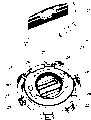
Fig. 1 is the decomposition diagram of the whole selector button of the present invention; And individually represent with the ratio of another perspective view and amplification respectively according to Fig. 1;
Fig. 2 is a shell;
Fig. 3 is push-key (Knebel);
Fig. 4 is key-operated device;
Fig. 5 is No. 1 driving member; And
Fig. 6 is No. 2 driving members.
Embodiment
The concrete parts of all three solutions of the whole modular selection button of the present invention (modulare Wahlttaste) in Fig. 1, have been expressed, that is: a push-key (Knebel) 10, a knob 11 and a key-operated device 2 as rotary manipulation mechanism (Handhabe), a front locating snap ring 3, No. 1 driving member 4, No. 2 driving members 5, No. 1 driving member 4 of a distortion ', No. 2 driving members 5 of a distortion ', a shell 6, a control push rod 81, the control push rod respectively is with a compression spring 82, and No. 1 stop slide plate 91 and No. 2 stop slide plates 92.
On selector button according to the present invention's first solution, be provided with push-key (Knebel) 10 or button 11 as required, front locating snap ring 3, be provided with as required No. 1 or No. 2 driving members 4 or 5, shell 6, one or two is furnished with the control push rod 81 of compression spring 82 separately, as required not if be provided with one or two No. 2 stop slide plates 92.
On selector button, be provided with key-operated device 2 according to the present invention's second solution, front locating snap ring 3, be provided with as required or No. 2 driving members 4 ' or 5 ' No. 1 of distortion, shell 6, one or two is furnished with the control push rod 81 of compression spring 82 separately, as required not if be provided with one or two No. 1 or No. 2 stop slide plates 91 or 92.
On selector button according to the present invention's the 3rd solution, be provided with push-key (Knebel) 10 or button 11 or key-operated device 2 as required, front locating snap ring 3, be provided with as required No. 1 or No. 2 driving members 4 or 5 or No. 1 of distortion or No. 2 driving members 4 ' or 5 ', one or two is furnished with the control push rod 81 of compression spring 82 separately, as required not if be provided with one or two No. 1 or No. 2 stop slide plates 91 or 92.
Because three solutions have many features and act on all is identical, the feature and the effect of corresponding two or whole three solutions are described together below.
Two control push rods 81 insert shell 6 from the back side, and wherein, 83 guiding of their two outer edge separately and fixation are surrounded by the guide plate 61 of two wide spacings in the inside of cylindrical shell 6 (Fig. 2) basically.Spiral compression spring 82 is bearing in respectively between No. 2 bearings 62 in control No. 1 bearing 84 on the push rod 81 and the shell 6, thereby control push rod 81 can pass through compression spring 82 and load towards the operating mechanism direction.No. 3 bearings 85 that are positioned at No. 1 bearing 84 opposites on control push rod 81 limit along operating mechanism (Handhabe) direction by the motion of stop to the back side of No. 2 bearings 62.Discoidal driving member 4,4 ', 5 or 5 ' will insert shell 6 from the front.After operating mechanism (Handhabe) 10,11 or 2 installs on the shell 6, put front locating snap ring 3 through operating mechanism (Handhabe) 10,11 or 2, and be clamped on the shell 6 in the front by means of general clamping element.Like this, make operating mechanism (Handhabe) 10,11 or 2 with permanent fastening linking to each other of shell, can't come off, simultaneously, push-key (Knebel) 10 or knob 11 are being with a back side guiding collar 13 to turn.On the contrary, it is not rotatable that 2 of key-operated devices are being with a back side fixed card ring 27, and is embedded in the gathering sill 65 of outer casing frontispiece.Stop slide plate 91 and 92 is designed to bar shaped, and there is radially the fastener 93 that protrudes at its rear portion, insert between two blocks of narrow fixed guide plates 61 from behind after, fasten in the contrary fastener 64 of shell 6 corresponding window-shaped.No. 1 driving member 4 and No. 2 driving members 5 are provided with a printing opacity fracture 45 or 55 (Fig. 5 and Fig. 6) at the middle part, the light source that this printing opacity fracture allows to utilize the back side to link to each other with selector button throws light on to push-key (Knebel) 10 or knob 11.Driving member 4,4 ', 5 or 5 ' be furnished with lip ring 40 at periphery, be used for preventing that moisture from entering the inside of selector button, and between movable members, keep the tolerance equilibrium.
According to Fig. 1 and Fig. 5 or Fig. 6, No. 1 driving member 4 or 4 ' and No. 2 driving members 5 or 5 ' the back side 41 or 51 on respectively be provided with two control curved surface elements 42 and 52 that axially protrude, this control curved surface element concurs by this way with the end face 86 of control push rod 81 in the front, that is: rotate driving member 4,4 ', 5 or 5 ' when leaving its resting position, control push rod 81 moves the contact element of not expressing in the control diagram backward facing to the effect of compression spring 82.On push-key (knebel) 10 and knob 11, be provided with opposed overleaf rib shape segment 12 (Fig. 3), when lifting push-key (knebel) 10 or knob 11, this rib shape segment embeds opposed groove shape segment 43 on No. 1 driving member 4 fronts 44 of respective design rigidly, or embeds the groove shape segment 53 on driving member 5 fronts 54 No. 2.Whereby, the rotational motion of push-key (knebel) 10 or knob 11 be passed to No. 1 or No. 2 driving members 4 or 5 on.
According to Fig. 1 and Fig. 4, key-operated device 2 is made of spring lock 22 key 21 and, and this spring lock is rigidly fixed on the shrouding 23, so can not rotate.Shrouding 23 has two arris lugs 24 on its collar 27, shell 6 on top has the groove 63 of respective design in the edge zone, and shrouding 23 utilizes this groove location to be installed in exactly in the shell 6 in the one side.The back side under the synergy of No. 1 stop 66, guarantees that the spring lock that shrouding 23 can not be inconjunction with in the shell 6 rotates along the opposed depression 29 of diametric(al) on the collar 27 in shell 6 gathering sills 65.Two strip structures 26 can be arranged overleaf with the lock core 25 of key turns, when key-operated device 2 is placed on the shell 6, this strip structure rigidly No. 1 of embedding distortion or No. 2 driving members 4 ' or 5 ' front 44 ' or 54 ' go up respective design grooves 43 ' or 53 ' in.Like this, the rotational motion of key 21 will be delivered to or No. 2 driving members 4 No. 1 of distortion ' or 5 '.
((knebel) 10 or knob 11 are during as operating mechanism (Handhabe), and selector button can dispose three switching positions, in other words, can dispose a middle part resting position and each clockwise direction and turned position counterclockwise using push-key.In an embodiment, use among Fig. 1 and Fig. 5 and show out driving member No. 1, its control curved surface element 42 is opposed symmetrically in an acute angle.In resting position, the central authorities of control curved surface element 42 between two control push rods 81.In a direction or when on another direction, rotating push-key (knebel) 10 or knob 11, always have a control curved surface element to head on the compression spring 82 of affiliated control push rod 81 in two control curved surface elements 42, it loads to the inclined plane 87 of an end face that always adjoins 86.If there is not the stop slide plate to inject, in 42 draw-in groove 88 scopes of relevant control curved surface element with control push rod 81 end faces 86 under its curved surface peak dot 46 arrival.Selector button rests on this jammed turned position, till making it leave this position by conscious operation.In order to limit the angle of rotation on the both direction, predesignated the first cover stopping element.The first cover stopping element is formed along the opposed No. 1 check shelves 14 of diametric(al) along opposed No. 1 stop 66 of diametric(al) and two by two, wherein, No. 1 stop 66 is designed to lug shape, be outwardly directed to along radial direction in the gathering sill 65 of shell 6, No. 1 check shelves then are designed to the guiding collar 13 upper edge radial directions bow-shaped section inwardly at push-key (knebel) 10 or knob 11, simultaneously, the side 67 that not only radially changes but also change vertically of No. 1 stop 66 concurs with the side 15 of corresponding No. 1 check shelves 14.
By No. 2 stop slide plates 92 are inserted in the shell 6, formed the 5th cover stopping element, this cover stopping element is effective when the resting position of rotating before selector button leaves the first cover stopping element.The 5th cover stopping element is by constituting along opposed two No. 2 stop surfaces 95 of diametric(al) and two No. 4 check shelves 47, wherein, No. 2 stop surfaces 95 are by anterior formation the in the narrow limit relative with rotation direction of No. 2 stop slide plates 92 of respective design, No. 4 check shelves 47 are then in the axial withdrawal spacing, symmetry is opposed in an acute angle, be arranged on the back side 41 of No. 1 driving member 4, simultaneously, No. 2 stop surfaces 95 and the check shelves 47 that angular displacements take place with respect to control curved surface element 42 are not only radially but also the arris face 471 common same-actions that rise that change vertically.Control curved surface element 42 in this case like this, the rotational angle of selector button is restricted, to such an extent as to no longer can make the scope of draw-in groove 88 of the end face 86 of the control push rod 81 of its curved surface peak dot 46 under entering.In this case, selector button is shown as the button maneuverability pattern on two turned positions, because after releasing operation mechanism (Handhabe) 10 and 11, selector button is by effect and the inclined plane 87 of control push rod 81 and the effect of working in coordination of control curved surface element 42 of compression spring 82, leave the turned position voluntarily, turn back to resting position.
When using push-key (knebel) 10 or knob 11 as operating mechanism (Handhabe), selector button also can dispose two switching positions, in other words, can dispose a resting position and a clockwise direction turned position.In the present embodiment, will use Fig. 1 and Fig. 6 table to go out driving member 5 No. 2, its control curved surface element 52 is opposed, unusually along the diameter transposition, i.e. and 180 ° of displacements.In resting position, adjoin on the inclined planes 87 of two control push rods 81 that always go before when control curved surface element 52 and rotation.When rotating push-key (knebel) 10 or knob 11, each of two control curved surface elements 52 heads on its compression spring 82 and loads to the inclined plane 87 of affiliated control push rod 81 correspondences.If there is not the stop slide plate to inject, in 52 draw-in groove 88 scopes of relevant control curved surface element with control push rod 81 end faces 86 under its curved surface peak dot 56 arrival.So just blocked the turned position.In order to limit rotational angle, provide the second cover stopping element in advance.The second cover stopping element is formed along the opposed No. 2 check shelves 59 of diametric(al) along opposed No. 2 stops 68 of diametric(al) and two by two, wherein, No. 2 stops 68 occur as the end face of two fan-shaped depressions 69 that form in shell 6 along diametric(al) in the clockwise direction, No. 2 check shelves 59 are then in the axial withdrawal spacing, opposed along diametric(al), on the back side 51 of No. 2 driving members 5, form, and radially be arranged in the outside of control curved surface element 52 fronts respectively, simultaneously, No. 2 stops 68 and No. 2 check shelves 59 corresponding preceding arris 591 synergies in rotational direction.Act on the resting position that just can reach by the effect of compression spring 82 and the inclined plane 87 of control push rod 81 with working in coordination of control curved surface element 52, selector button has disposed the 6th cover stopping element.This cover stopping element is made up of No. 4 stops 70 that always occur as the end face of fan-shaped depression 69 in the counterclockwise direction and No. 2 check shelves 59, and wherein, the corresponding arris 592 afterwards of No. 4 stops 70 and No. 2 check shelves 59 concurs.
In order to realize the button maneuverability pattern, will be inserted in the shell 6 by No. 2 stop slide plates 92, formed the 5th cover stopping element again, this cover stopping element plays a role when the resting position of rotating before selector button leaves the second cover stopping element.In this case, the 5th cover stopping element is made up of No. 2 stop surfaces 95 and No. 4 check shelves 57 on No. 2 unique moving slide plates 92, these No. 4 check shelves are in the axial withdrawal spacing, on the back side 51 of No. 2 driving members 5, form, wherein, No. 2 stop surfaces 95 not only radially but also at the arris face 571 that axially changes are acting synergistically with the check shelves 57 that angular displacement takes place with respect to control curved surface element 52.Control curved surface element 52 like this, the rotational angle of selector button is restricted, to such an extent as to no longer can make its curved surface peak dot 56 enter the scope of draw-in groove 88 of the end face 86 of relevant control push rod 81.
Push-key (knebel) 10 has been equipped with the rib shape segment 12 of some, and its quantity has surpassed the quantity of groove shape segment 53 on No. 2 driving members 5.Therefore, push-key (knebel) 10 can utilize No. 2 driving members 5 to be admitted to two different cooperation positions selectively.A horizontal installation site that has disposed the selector button of two switching positions, push-key (knebel) 10 occupies the turned position that angular displacement takes place a vertical resting position (0 °) and and this position (for example+30 °) on a cooperation position, on the contrary, on another each cooperation position, then occupy a resting position (for example-15 °) and one turned position of symmetry (for example+15 °) with it with respect to vertical line generation angular displacement.
Using under the situation of key-operated device 2 as operating mechanism (Handhabe), selector button also can dispose three switching positions.In the present embodiment, with use No. 1 driving member 4 of represented distortion among Fig. 1 ', on its control curved surface element 42 and No. 4 check shelves 47 and No. 1 driving member 4 recited above situation identical.Under the situation that does not snap in slide block, also can realize snap-in maneuverability pattern, will reach full rotational angle in this case, allow to discharge or extract the key 21 that is on the turned position.In order on both direction, to determine full rotational angle, be provided with the 3rd cover stopping element.This cover stopping element by two along opposed No. 3 stops 28 of diametric(al) and two along the opposed No. 3 check shelves 48 of diametric(al) ' form, wherein, No. 3 stop 28 designs as bow-shaped section, axial orientation is on the back side of fixing spring lock 22, No. 3 check shelves 48 ' then be designed to lug shape, radial inward be oriented in No. 1 driving member 4 of distortion ' front 44 ' on, simultaneously, the side 481 of No. 3 stops 28 side 281 of not only radially changing but also changing vertically and No. 3 check shelves 48 ' accordingly ' concur.
In this case, distortion No. 1 driving member 4 ' No. 4 check shelves 47 constitute in order to realize the 5th cover stopping elements of button maneuverability pattern with No. 2 stop surfaces 95 that are inserted into No. 2 stop slide plates 92 in the shell 6 are common.Because rotational angle is restricted, can not extract key 21 on the turned position.
Replace inserting No. 2 stop slide plates 92 by inserting No. 1 stop slide plate 91, to form the quadruplet stopping element, this cover stopping element is when key executor 2 leaves resting position, both the rotation direction before the 3rd cover stopping element worked, and the rotation direction in the 5th cover stopping element back mentioned above works again.Therefore, though realized snap-in maneuverability pattern again, because rotational angle still is restricted, key 21 still can not be pulled out on the turned position, because it just will be fixed when the full rotational angle that does not reach in spring lock 22.The quadruplet stopping element by No. 1 driving member 4 of opposed No. 1 stop surface 94 and distortion ' No. 4 check shelves 47 form, wherein, No. 1 stop surface 94 is made of on the surface at rear portion the otch 97 of the front portion that is positioned at No. 1 stop slide plate 91 and narrow limit 96 corresponding rotation direction opposition.Two stop slide plate 91 minute surfaces are symmetrical in its narrow limit 96 as symmetry axis, are otch 97 with the main distinction of No. 2 stop slide plates 92.Have in two stop slide plates 91 a stop slide plate at its rear portion with No. 1 cutting 99 as identification code, No. 2 cuttings 71 below this No. 1 cutting and the shell 6 interior contrary fasteners 64 are consistent, so that guarantee each piece stop slide plate of No. 1 stop slide plate 91 of two minute surface symmetries are arranged on the tram in the shell 6.
When using key-operated device 2 as operating mechanism (Handhabe), selector button also can dispose two switching positions.In the present embodiment, with use No. 2 driving members 5 showing out distortion among Fig. 1 ', the situation with No. 2 driving members 4 mentioned above is identical in design with No. 4 check shelves 57 for 52, No. 2 check shelves 59 of its control curved surface element.On the turned position, under the situation that does not snap in slide block, also can discharge key 21.When snapping in the turned position, still be subjected to the restriction of the 3rd cover stopping element with the motion that can discharge key 21, this cover stopping element by No. 3 stops 28 that had on the spring lock 22 and No. 2 driving members 5 of distortion ' front 54 ' on No. 3 check shelves 58 ' form that form, No. 1 driving member 4 that these No. 3 check shelves are equivalent to be out of shape ' No. 3 check shelves 48 '.Here, the restriction on resting position is to be caused by the 6th cover stopping element that is included in No. 4 stops 70 in the shell 6 and No. 2 check shelves 59.
By having only No. 1 a stop slide plate 91 to be inserted in the shell 6, with No. 2 driving members 5 of distortion ' the synergy of No. 4 check shelves 57 under, formed the quadruplet stopping element again, this cover stopping element with the synergy of spring lock 22 under, key 21 is fixed on the turned position that snaps in.
Here, the restriction to rotational motion under the button maneuverability pattern also can be caused by the 5th cover stopping element, and this cover stopping element is made up of No. 2 stop slide plates 92 and No. 4 check shelves 57.
The present invention is not limited to form of implementation recited above, but also is included in the form of implementation that has same purpose on the original idea of the present invention.Can also adopt a kind of operating mechanism (Handhabe) with same purpose, to replace described operating mechanism (Handhabe), for example, employing has the action bars of corresponding moulding on end face, this action bars from the front directly with No. 1 that is out of shape or No. 2 driving members 4 ' or 5 ' groove 43 ' or 53 ' cooperate, and can break away from this groove again.Under the situation of three switching positions of selector button configuration, in order only to realize snap-in or button maneuverability pattern in a corresponding rotation direction (key can discharge or be maintained fixed in case of necessity), also might use No. 1 stop slide plate 91 own separately, No. 2 stop slide plate 92 itself, or be used in combination No. 1 and No. 2 stop slide plates 91 and 92.Can also implement regulation approach of the present invention by only using a single control push rod 81 to simplify certain purposes.In order to alleviate the burden of reliability, can also only design No. 1, No. 2 and No. 3 stops 66,68 and 28.
The code name list:
10 push-keys (knebel)
11 knobs, 56 curved surface peak dots
57 No. 4 check shelves of 12 rib shape segments
13 guiding collars, 571 arris faces
59 No. 2 check shelves of 14 No. 1 check shelves
15 sides, 591 front arris
2 key-operated device 592 rear arris
No. 2 driving members of 21 keys 5 ' distortion
22 spring locks, 53 ' groove
23 shroudings, 54 ' front
58 ' No. 3 check shelves of 24 lugs
25 lock cores, 6 shells
26 strip structures, 61 guide plates
62 No. 2 bearings of 27 fixed card rings
28 No. 3 stop 63 grooves
281 sides, 64 contrary fasteners
29 depressions, 65 gathering sills
66 No. 1 stops of 3 front locating snap rings
4 No. 1 driving member 67 sides
68 No. 2 stops of 40 lip rings
41 back sides, 69 depressions
70 No. 4 stops of 42 control curved surface elements
71 No. 2 cuttings of 43 groove shape segments
44 positive 81 control push rods
45 printing opacity fractures, 82 compression springs
46 curved surface peak dots, 83 outer edge
84 No. 1 bearings of 47 No. 4 check shelves
85 No. 3 bearings of 471 arris faces
No. 1 driving member 86 end faces of 4 ' distortion
43 ' groove, 87 inclined planes
44 ' positive 88 draw-in grooves
91 No. 1 stop slide plates of 48 ' No. 3 check shelves
The 92 No. 2 stop slide plates in 481 ' side
5 No. 2 driving member 93 fasteners
94 No. 1 stop surfaces in 51 back sides
95 No. 2 stop surfaces of 52 control curved surface elements
53 groove shape segments, 96 narrow limits
54 positive 97 otch
55 printing opacity fractures, 98 narrow limits
99 No. 1 cuttings
Claims (15)
1. in order to the modular selection button of control contact element, comprise
A shell (6);
A push-key (10) or knob (11) are as rotating operating mechanism;
One is connected the driving member (4,5) that operating mechanism (10,11) is gone up and settled un-rotatably in shell (6), this driving member is supporting a control curved surface that can axially work;
By with respect to shell (6) fixing stop with can form, in order to limit the stopping element of operating mechanism (10,11) rotational angle with the check shelves that operating mechanism (10,11) rotates;
At least one places in the shell (6) un-rotatably and can head on the control push rod (81) that spring element (82) carries out displacement, this control push rod concurs through an end face that is symmetrically formed (86) and control curved surface forward, wherein, control curved surface and end face (86) are designs like this, that is: when reaching the regulation rotational angle of relative resting position, driving member (4,5) is stuck on the control push rod (81);
It is characterized in that,
Driving member (4,5) is designed to disc, and overleaf (41,51) bolster to the control curved surface element (42,52) of space out;
With respect to the described operating mechanism of resting position (10,11) when snapping onto the turned position, described stopping element is as the stopping element of each rotation direction:
When disposing three switching positions: use the first cover stopping element, form by No. 1 check shelves (14) in No. 1 stop (66) in the shell (6) and the operating mechanism (10,11);
And when two switching positions of configuration: use the second cover stopping element, form by No. 2 stops (68) in the shell (6) and No. 2 check shelves (59) on the driving member (5);
When arriving the turned position with respect to the resting position button, described stopping element is as the stopping element of each rotation direction: use the 5th cover stopping element, by adopting the mode of snapping in to insert No. 2 stop slide plates (92) of shell (6) and No. 4 check shelves (47,57) on the driving member (4,5) are formed, wherein, on the rotation direction in No. 2 stop surfaces (95) of No. 2 stop slide plates (92) and the angular interval between No. 4 check shelves (47,57) less than the angular interval between the first or second cover stopping element (66,14,68,59).
2. composite type according to claim 1 is selected button, it is characterized in that, No. 2 stop slide plates (92) are designed to bar shaped, on the anterior narrow limit (98) relative of described stop slide plate (92), be provided with stop surface (95) with operating mechanism (10,11) rotation direction, there is fastener (93) at its rear portion, in the corresponding contrary fastener (64) that snaps in shell (6).
3. composite type according to claim 1 is selected button, it is characterized in that, in shell (6), be provided with two identical control push rods (81) radially relative, longitudinal extension, be provided with two No. 1 identical and No. 2 stops (66,68), No. 2 stop slide plates (92) also are provided with two identical contrary fasteners (64).
4. select button in order to the composite type of control contact element, comprise
A shell (6);
A rotating operating mechanism (2);
One is connected un-rotatably that operating mechanism (2) is gone up and the driving member of arrangement shell (6) in (4 ', 5 '), and this driving member is supporting a control curved surface that can axially work;
By with respect to shell (6) fixing stop with can form, in order to the stopping element of the rotational angle that limits operating mechanism (2) with the check shelves that operating mechanism (2) rotates;
At least one places in the shell (6) un-rotatably and can head on the control push rod (81) that spring element (82) carries out displacement, this control push rod concurs with control curved surface through the end face (86) that a symmetry is shaped forward, wherein, control curved surface and end face (86) are designs like this, that is: when reaching the regulation rotational angle of relative resting position, driving member (4 ', 5 ') is stuck on the control push rod (81);
It is characterized in that,
Operating mechanism is a key-operated device (2);
Driving member (4 ', 5 ') is designed to disc, and overleaf (41,51) bolster to the control curved surface element (42,52) of space out;
With respect to the described operating mechanism of resting position (2) when snapping onto the turned position, described stopping element is as the stopping element of each rotation direction:
When the key that can extract on the turned position (21) is on the turned position: use the 3rd cover stopping element, form with respect to No. 3 check shelves on driving member (4 ', 5 ') of fixing No. 3 stops (28) of shell (6) and (48 ', 58 ') by one;
When the key that can not extract on the turned position (21) is on the turned position: use the quadruplet stopping element, snap in No. 4 check shelves (47,57) that mode inserts on No. 1 stop (91) in the shell (6) that opens wide at the back side and the driving member (4 ', 5 ') from behind and form by available, wherein, on the rotation direction in No. 1 stop surface (94) of No. 2 stop slide plates (91) and the angular interval between No. 4 check shelves (47,57) less than the angular interval between the 3rd cover stopping element (28,48 ', 28,58 ');
When arriving the turned position with respect to the resting position button, described stopping element is as the stopping element of each rotation direction: use the 5th cover stopping element, form by No. 4 check shelves (47,57) that No. 2 stop slide plates (92) that can adopt the mode of snapping in to insert shell (6) replace on No. 1 stop slide plate (91) and the driving member (4 ', 5 '), wherein, No. 1 stop slide plate (94) that is positioned at No. 1 stop slide plate (91) at No. 2 stop surfaces (95) of No. 2 stop slide plates (92) on rotation direction before.
5. composite type according to claim 4 is selected button, it is characterized in that, in shell (6), be provided with two identical control push rods (81) radially relative, longitudinal extension, be provided with two identical No. 3 stops (28), also be provided with two identical contrary fasteners (64) with No. 2 stop slide plates (91,92) No. 1.
6. select button in order to the composite type of control contact element, comprise
A shell (6);
A rotating operating mechanism (10,11,2);
One is connected on the operating mechanism (10,11,2) and in shell (6) un-rotatably
In the driving member (4,4 ', 5,5 ') settled, this driving member is supporting a control curved surface that can axially work;
By with respect to shell (6) fixing stop with can form, in order to the stopping element of the rotational angle that limits operating mechanism (10,11,2) with the check shelves that operating mechanism (10,11,2) rotates;
At least one places in the shell (6) un-rotatably and can head on the control push rod (81) that spring element (82) carries out displacement, this control push rod is forward through an end face that is symmetrically formed (86) and control curved surface synergy, wherein, control curved surface and end face (86) are designs like this, that is: when reaching the rotational angle of relative resting position regulation, driving member (4,4 ', 5,5 ') is stuck on the control push rod (81);
It is characterized in that,
Driving member (4,4 ', 5,5 ') is designed to disc, and overleaf (41,51) bolster to the control curved surface element (42,52) of space out;
With respect to the described control member of resting position (10,11,2) when snapping onto the turned position, described stopping element is as the stopping element of each rotation direction:
And with a push-key (10) or knob (11) during as operating mechanism,
When disposing three switching positions: use the first cover stopping element, form by No. 1 check shelves (14) in No. 1 stop (66) in the shell (6) and the operating mechanism (10,11),
And when two switching positions of configuration: use the second cover stopping element, form by No. 2 stops (68) in the shell (6) and No. 2 check shelves (59) on the driving member (5),
But with a key-operated device (2) during as operating mechanism,
When the key that can extract on the turned position (21) can be on the turned position: use the 3rd cover stopping element, form with respect to No. 3 check shelves on driving member (4 ', 5 ') of fixing No. 3 stops (28) of shell (6) and (48 ', 58 ') by one;
And when when the key that can not extract on the turned position (21) is on the turned position: use the quadruplet stopping element, snap in No. 4 check shelves (47,57) that mode inserts on No. 1 stop (91) in the shell (6) that opens wide at the back side and the driving member (4 ', 5 ') from behind and form by available, wherein, be slightly less than angular interval between the 3rd cover stopping element (28,48 ', 28,58 ') in No. 1 stop surface (94) of No. 2 stop slide plates (91) and the angular interval between No. 4 check shelves (47,57) on the rotation direction;
When arriving the turned position with respect to the resting position button, described stopping element is as the stopping element of each rotation direction: use the 5th cover stopping element, form by No. 4 check shelves (47,57) that can adopt the mode of snapping in to insert on one of shell (6) No. 2 stop slide plates (92) that replace No. 1 stop slide plate (91) and the driving member (4,4 ', 5,5 '), wherein, No. 1 stop slide plate (94) that is positioned at No. 1 stop slide plate (91) at No. 2 stop surfaces (95) of No. 2 stop slide plates (92) on rotation direction before.
7. select button according to claim 4 or 6 described composite types, it is characterized in that, No. 1 and No. 2 stop slide plates (91,92) are designed to bar shaped, at described stop slide plate (91,92) the anterior narrow limit (96,98) relative with operating mechanism (10,11,2) rotation direction is provided with stop surface (94,95), there is fastener (93) at its rear portion, in the corresponding contrary fastener (64) that snaps in shell (6); No. 1 stop slide plate (91) relative with No. 2 stop slide plates (92) forwardly is provided with a kerf (97) to form No. 1 stop surface (94).
8. composite type according to claim 6 is selected button, it is characterized in that, in shell (6), be provided with two identical control push rods (81) radially relative, longitudinal extension, be provided with two No. 1, No. 2 identical and No. 3 stops (66,68,28), also be provided with two identical contrary fasteners (64) with No. 2 stop slide plates (91,92) No. 1.
9. select button according to any described composite type in the claim 3,5 and 8, it is characterized in that, be that three switching positions have been stipulated No. 1 driving member (4,4 '), on its back side (41), two control curved surface elements (42) and rotate respectively around an acute angle degree with two axial withdrawal spacings of angular shift take place described control curved surface element (42) No. 4 check shelves (47) make the in addition displacement mutually of symmetry of formation.
10. select button according to any described composite type in the claim 3,5 and 8, it is characterized in that, be that two switching positions have been stipulated No. 2 driving members (5,5 '), on its back side (51), two control curved surface elements (52) become No. 2 check shelves (59) of 180 ° of degree layouts and two axial withdrawal spacings to be arranged in the outside of control curved surface element (52) front.
11. composite type according to claim 10 is selected button, it is characterized in that, has stipulated the 6th cover stopping element for resting position, forms along opposed No. 4 stops of diametric(al) (70) and No. 2 check shelves (59) in shell (6) by two.
12. select button according to claim 1 or 6 described composite types, it is characterized in that, be arranged in the rib shape segment (12) on the operating mechanism that is designed to push-key (10) or knob (11) overleaf, with the groove shape segment (43,53) that is arranged in the front on the driving member (4,5), can realize that each other rigidity cooperates.
13. composite type according to claim 12 is selected button, it is characterized in that, operating mechanism (10,11) has two cooperation positions that angular shift takes place mutually at least with No. 2 driving members (4,5).
14. select button according to claim 1 or 6 described composite types, it is characterized in that driving member (4,5) is provided with a printing opacity fracture (45,55).
15. select button according to claim 4 or 6 described composite types, it is characterized in that when using a key-operated device (2) as operating mechanism, a spring lock (22) is connected with shell (6) un-rotatably by a shrouding (23); The strip structure (26) at rotating lock core (25) back side embeds in the front groove (43 ', 53 ') of a driving member that is out of shape with respect to driving member (4,5) (4 ', 5 ') rigidly; No. 3 stops (28) are arranged in the back side of spring lock (22), and No. 3 check shelves (48 ', 58 ') are arranged in the front of the driving member (4 ', 5 ') of described distortion.
Applications Claiming Priority (2)
| Application Number | Priority Date | Filing Date | Title |
|---|---|---|---|
| DE19962291A DE19962291A1 (en) | 1999-12-23 | 1999-12-23 | Modular selection key for operating contact elements key, has rotating button or key operator as a turnable grip and transmission links for transferring motion from the grip |
| DE19962291.4 | 1999-12-23 |
Publications (2)
| Publication Number | Publication Date |
|---|---|
| CN1341264A CN1341264A (en) | 2002-03-20 |
| CN1254832C true CN1254832C (en) | 2006-05-03 |
Family
ID=7933998
Family Applications (1)
| Application Number | Title | Priority Date | Filing Date |
|---|---|---|---|
| CNB008041784A Expired - Lifetime CN1254832C (en) | 1999-12-23 | 2000-12-13 | Modular selection button |
Country Status (12)
| Country | Link |
|---|---|
| US (1) | US6872905B2 (en) |
| EP (1) | EP1155426B1 (en) |
| JP (1) | JP2003518716A (en) |
| CN (1) | CN1254832C (en) |
| AT (1) | ATE356418T1 (en) |
| CZ (1) | CZ302093B6 (en) |
| DE (2) | DE19962291A1 (en) |
| ES (1) | ES2283336T3 (en) |
| HU (1) | HU227266B1 (en) |
| PL (1) | PL198076B1 (en) |
| PT (1) | PT1155426E (en) |
| WO (1) | WO2001048769A1 (en) |
Families Citing this family (24)
| Publication number | Priority date | Publication date | Assignee | Title |
|---|---|---|---|---|
| US7161253B2 (en) * | 2003-08-06 | 2007-01-09 | Briggs & Stratton Corporation | Portable power source |
| PL1697953T3 (en) | 2003-12-17 | 2007-09-28 | Schneider Electric Ind Sas | Luminous turning button |
| FR2864334B1 (en) * | 2003-12-17 | 2007-04-06 | Schneider Electric Ind Sas | BRIGHT TURN BUTTON |
| FR2864333B1 (en) * | 2003-12-17 | 2007-03-30 | Schneider Electric Ind Sas | BRIGHT TURN BUTTON |
| FR2882463B1 (en) * | 2005-02-24 | 2007-03-30 | Schneider Electric Ind Sas | TURN BUTTON WITH LOCK |
| EP2019400B1 (en) * | 2007-07-23 | 2013-03-27 | Eurotec Engineering Ltd. | Key operated switch with touch and locking function |
| JP4589414B2 (en) * | 2008-01-30 | 2010-12-01 | 株式会社東海理化クリエイト | Disconnect switch device for industrial vehicles |
| DE102013105165B4 (en) | 2013-05-21 | 2015-05-28 | R. Stahl Schaltgeräte GmbH | Actuating attachment for actuating a button and / or switch |
| FI125669B (en) * | 2013-08-15 | 2016-01-15 | Abloy Oy | cylinder lock |
| JPWO2015151882A1 (en) * | 2014-04-03 | 2017-04-13 | 株式会社東海理化電機製作所 | Switch device |
| CN106816333A (en) * | 2015-11-27 | 2017-06-09 | 浙江正泰电器股份有限公司 | Operation of push-button switch mechanism |
| CN109690717B (en) * | 2016-09-08 | 2020-05-15 | 松下知识产权经营株式会社 | Rotary input device |
| CN107726650B (en) * | 2017-11-13 | 2024-04-09 | 浙江格莱智控电子有限公司 | Control instrument for solar water heater not prone to failure |
| CN107702359B (en) * | 2017-11-13 | 2024-04-09 | 浙江格莱智控电子有限公司 | Safe and reliable's control instrument for solar water heater |
| CN107993865A (en) * | 2017-12-08 | 2018-05-04 | 苏州特铭精密科技有限公司 | A kind of double button chute-type pressing knob assembling devices |
| CN107962382B (en) * | 2017-12-08 | 2019-05-03 | 苏州特铭精密科技有限公司 | A kind of dual-purpose chute-type pressing knob assembly device |
| CN108032079B (en) * | 2017-12-08 | 2019-06-07 | 苏州特铭精密科技有限公司 | A kind of double key chute-type pressing knob knob pedestal assembly devices |
| CN107863262A (en) * | 2017-12-08 | 2018-03-30 | 苏州特铭精密科技有限公司 | A kind of single-button chute-type pressing knob assembling device |
| CA3041498A1 (en) | 2018-04-27 | 2019-10-27 | Cascades Canada Ulc | Locking assembly for a dispenser and dispenser |
| CN108615641A (en) * | 2018-05-09 | 2018-10-02 | 浙江天正电气股份有限公司 | a kind of rotary switch |
| CN108766825B (en) * | 2018-05-12 | 2023-11-24 | 惠州市德赛西威汽车电子股份有限公司 | Vehicle-mounted knob assembly |
| CN110676089B (en) * | 2019-09-24 | 2022-01-04 | 深圳供电局有限公司 | Electric equipment operation program lock and operation method thereof |
| CN113035629A (en) * | 2019-12-24 | 2021-06-25 | 菲尼克斯亚太电气(南京)有限公司 | Rotary switch with light guide and different gears |
| CN114695002B (en) * | 2022-04-08 | 2023-10-24 | 中国第一汽车股份有限公司 | Knob type switch for automobile |
Family Cites Families (8)
| Publication number | Priority date | Publication date | Assignee | Title |
|---|---|---|---|---|
| US3517570A (en) * | 1968-08-07 | 1970-06-30 | Honeywell Inc | Multi-position rotary actuating mechanism |
| GB1299727A (en) * | 1968-12-20 | 1972-12-13 | Telemeccanica Elettrica Ohg Ri | Rotary selector switch |
| US4175220A (en) * | 1977-12-07 | 1979-11-20 | Westinghouse Electric Corp. | Convertible selector switch |
| DE2903066C3 (en) * | 1979-01-26 | 1981-07-09 | Siemens AG, 1000 Berlin und 8000 München | Command switch with rotary drive |
| DE3412518A1 (en) * | 1984-04-04 | 1985-10-24 | Klöckner-Moeller Elektrizitäts GmbH, 5300 Bonn | Control key with rotating drive |
| CH666765A5 (en) * | 1985-02-08 | 1988-08-15 | Sprecher & Schuh Ag | OPERATING DEVICE FOR A SWITCH WITH A ROTATABLE HANDLE. |
| DE3521155A1 (en) * | 1985-06-13 | 1986-12-18 | Brown, Boveri & Cie Ag, 6800 Mannheim | Operating element for an explosion-proof switch |
| US4737608A (en) * | 1987-07-10 | 1988-04-12 | Illinois Tool Works Inc. | Convertible rotary switch |
-
1999
- 1999-12-23 DE DE19962291A patent/DE19962291A1/en not_active Withdrawn
-
2000
- 2000-12-13 CN CNB008041784A patent/CN1254832C/en not_active Expired - Lifetime
- 2000-12-13 AT AT00983305T patent/ATE356418T1/en active
- 2000-12-13 EP EP00983305A patent/EP1155426B1/en not_active Expired - Lifetime
- 2000-12-13 WO PCT/EP2000/012638 patent/WO2001048769A1/en active IP Right Grant
- 2000-12-13 PT PT00983305T patent/PT1155426E/en unknown
- 2000-12-13 ES ES00983305T patent/ES2283336T3/en not_active Expired - Lifetime
- 2000-12-13 JP JP2001548402A patent/JP2003518716A/en active Pending
- 2000-12-13 CZ CZ20013002A patent/CZ302093B6/en not_active IP Right Cessation
- 2000-12-13 PL PL349277A patent/PL198076B1/en unknown
- 2000-12-13 DE DE50014135T patent/DE50014135D1/en not_active Expired - Lifetime
- 2000-12-13 HU HU0200094A patent/HU227266B1/en not_active IP Right Cessation
- 2000-12-13 US US09/914,139 patent/US6872905B2/en not_active Expired - Lifetime
Also Published As
| Publication number | Publication date |
|---|---|
| PL198076B1 (en) | 2008-05-30 |
| ES2283336T3 (en) | 2007-11-01 |
| DE50014135D1 (en) | 2007-04-19 |
| EP1155426A1 (en) | 2001-11-21 |
| US6872905B2 (en) | 2005-03-29 |
| EP1155426B1 (en) | 2007-03-07 |
| CZ302093B6 (en) | 2010-10-06 |
| CN1341264A (en) | 2002-03-20 |
| DE19962291A1 (en) | 2001-06-28 |
| WO2001048769A1 (en) | 2001-07-05 |
| CZ20013002A3 (en) | 2001-11-14 |
| PT1155426E (en) | 2007-06-06 |
| JP2003518716A (en) | 2003-06-10 |
| HUP0200094A2 (en) | 2002-05-29 |
| HU227266B1 (en) | 2010-12-28 |
| US20030150701A1 (en) | 2003-08-14 |
| ATE356418T1 (en) | 2007-03-15 |
| PL349277A1 (en) | 2002-07-15 |
Similar Documents
| Publication | Publication Date | Title |
|---|---|---|
| CN1254832C (en) | Modular selection button | |
| CN1153880C (en) | Electromechanical cylinder lock | |
| CN1947957A (en) | Handheld rotary tool | |
| CN1416583A (en) | Emergency shutdown key | |
| CN101076641A (en) | System and method for configuring key | |
| CN1685295A (en) | Control unit for electric household appliance | |
| CN101337346A (en) | Vibrating hand machine tool with an arresting switch for the motor switch | |
| CN1296741C (en) | Focusing device | |
| CN104251079B (en) | A kind of mechanical code lock | |
| CN1490487A (en) | Variable coding cylinder lock head with side lever | |
| CN2853837Y (en) | Thread changing mechanism of circular knitting machine | |
| CN1416584A (en) | Emergency shutdown key system | |
| CN1317941A (en) | Hair plaiting device and its auxiliary device | |
| CN1519451A (en) | Lock possessing helical key passage and the key | |
| JP2014524641A (en) | Anti-theft lamp | |
| CN1775611A (en) | Protection device of cylinder lock for vehicle | |
| CN1578611A (en) | Swivel hinge and portable terminal using the same | |
| CN1383146A (en) | Tray discharger and tray clamping mechanism | |
| CN1905327A (en) | Rotation stopping device and geared motor | |
| JP2009095902A (en) | Hammering tool | |
| KR200483274Y1 (en) | Led lighting apparatus with controlling the direction of illumination | |
| CN1148769C (en) | Turned electric parts capable of generating click effect | |
| CN1175443C (en) | Emergency shutdown key | |
| WO2007070277A3 (en) | Masking to prevent overexposure and light spillage in microarray scanning | |
| CN1177856A (en) | Step-by-step motor |
Legal Events
| Date | Code | Title | Description |
|---|---|---|---|
| C10 | Entry into substantive examination | ||
| SE01 | Entry into force of request for substantive examination | ||
| C06 | Publication | ||
| PB01 | Publication | ||
| C14 | Grant of patent or utility model | ||
| GR01 | Patent grant | ||
| CX01 | Expiry of patent term | ||
| CX01 | Expiry of patent term |
Granted publication date: 20060503 |