The specific embodiment
The primary member of safety band rewinder 20 of the present invention comprises that a framework 22 and turns round bar/reel assembly 300, and as shown in figure 13, one section seat safety belt strap is reeled around this assembly.Fig. 1-the 4th, the various views of retractor framework 22.This retractor framework preferably comprises mould to be annotated and to form and glass fiber-reinforced thermoplastic plastic, and this thermoplastic plastic ties up to have weight density and be at least glass fibres 50% to about 70%, about 10 millimeters long in the nylon resin.Also can utilize carbon or aramid fibre to come fortified resins, this resin can be acetal or phenol, rather than nylon.Perhaps, in some application scenario, it is the glass fibre 2-3 millimeter, short that thermoplastic plastic also can adopt length.
Framework 22 has a base portion 24 and at least one installs feature portion, such as bottom fabricated section 60.As shown in the figure, this bottom fabricated section need not to adopt bolt or other fastener that separates that retractor is installed.This fabricated section is anchored retractor on an installation surface or structure, on car post or seat spare.Main body 24 be shaped as basic quadrangle, it has an inner chamber or the cavity 26 that has an open top 28, between erecting stage, the various retractor members such as spool are received in the inner chamber by this open top.
This main body comprises first or spring side 30 and second or mechanism side 32.Multiple pillar or Crossware is the whole combinations in two sides, so that intensity is provided, prevents to distort and guarantee the suitable orientation of framework and member thereof.Wherein some Crossware constitutes a trailing flank 34, this trailing flank with respect to its about the installation site of car post towards outside; Other Crossware then constitutes a leading flank 36, this leading flank with respect to its about the installation site of car post towards the lining.If retractor is installed in the mode of putting upside down, then the design meeting of this front and back sides changes to some extent.Each side 30 and 32 top 31 are roughly rectangular, and they are combined by the front and back pillar on top or Crossware 40a and 40b, to constitute an open top 28.The bottom 33 curved shapes of the left and right sides are so that allow frame assembled when being rectangle than the bottom in the littler space.The rear side of each bottom 33 and trailing flank 34 or outer ledge 42 are than front portion or inside edge 44 and leading flank 36 bending more.
The lower knuckle outer ledge 42 of the left and right sides by the integrally formed bottom that only constitutes the trailing flank 34 that extends along the part of every outer ledge 42 after lateral brace or Crossware 46 be connected.In Fig. 1, pillar 46 is spaced apart with upper strut 40a and fabricated section 60.Side 30 also is connected by long lower front side pillar or a Crossware 48 that constitutes the leading flank 36 (referring to Fig. 2) that extends along the edge 44 of each frame facet with 32.This pillar 48 is spaced apart with pillar 40b, and extends downward fabricated section 60, also constitutes the antetheca 62 of fabricated section.
Framework 22 comprises a middle lower portion pillar 66 of the bottom 33 that connects side 30 and 32.This center stanchion 66 is basically perpendicular to the bottom 74 of fabricated section and extends.When the fabricated section pressurized of bottom, pillar 66 helps these power is assigned on integrally formed frame facet 30 and 32.First rear wall of the bottom formation fabricated section 60 of center stanchion 66 or back are to wall 72.Pillar 48 and 66 is near be integrated the fabricated section (shown in the label among Fig. 3 49), so that the intensity of this part of crossing fabricated section of reinforcement is provided.
From Fig. 1-4, can see the details of fabricated section 60.This fabricated section is and has bottom 74 and the upwardly extending all walls in this bottom or side basket or hook-shaped certainly.One of them of these walls is formed by the wall 72 of the bottom of center stanchion 66.Laterally wall or side 76a and 76b are formed by the utmost point lower part of side 30 and 32.Following wide second back is connected side 76a, 76b to wall 78 with the bottom.The various members of fabricated section 60 constitute a structure container cavity 80.The shape of this cavity 80 has been shown among Fig. 3 and 4.One hook is formed on wall 72,78 and bottom 74, this hook with and mounting structure 90 such as B or C shape car post or seat mount spare the part 98 or the insert 100 that are associated be complementary, shown in Fig. 5 a.If need not structure support in some application scenario, then can remove wall 76a and 76b, this will make fabricated section 60 more be hook-shaped.Framework 22 can comprise in the bottom that is integrally formed in cavity 80 or the delivery orifice 77 at the infall of side 36 and pillar 66 and/or pillar 252 and the place, bottom of side 34, as shown in figs. 1 and 3.
Installation surface 90 is formed with first opening 92 that its size is enough to hold retractor framework 22, shown in Fig. 5 c.For retractor, quite generally be recessed in the opening of mounting structure 90.Fig. 5 a is the view of seeing towards the inside in compartment from the outside of vehicle, and it shows the rear side or the hidden side of B shape car post.Fig. 5 b shows the section drawing of the retractor framework that is arranged in B shape car post 90.The spool of not shown retractor and other member.Fig. 5 c be arranged in structure 90 retractor 20 towards outer block diagram.In the present invention, mounting structure comprises second opening 94 of a part that is enough to hold fabricated section 60.The intermediate structure part 96 of this structure 90 is spaced apart with two openings 92 and 94.The centre portion 96 of this car post can be formed with an available mounting portion 98 that extends in the opening 94.If you are using, the shape of this part 98 is preferably consistent with the shape of the cavity 80 of fabricated section 60, so that it is easy to closely be contained in this cavity.In preferred embodiment of the present invention, shown in Fig. 5 b, the depth d of the cavity 80 of fabricated section 60 is about 4 millimeters.If this size greater than the thickness of the mounting portion 98 of mounting structure 90, then adopts an insert 100 to tremble (rattle) to prevent the retractor framework on installation surface.The car post is normally formed by sheet metal.Insert 100 can or adopt the fastener that separates to be connected on the centre portion 96 of structure 90, so that it is reinforced by welding.Insert 100 can be a form metal, granulated metal or the cast metal part that has outstanding top 102.The cavity 80 of the profile on this top 102 and fabricated section 60 or the shape of hook are complementary.
Shown in Fig. 5 b, if adopt, top 102 and mounting portion 98 closely are assemblied in the cavity 80.The combination thickness of top 102 and parts 98 preferably equates with the depth d of cavity or hook.If structure 90 does not have parts 98 or not after top 102, then the thickness on top 102 suitably increases.Fig. 5 d shows another kind of situation of the present invention, and its cavity 80 is filled up by elastomeric material 104, perhaps includes elastomeric material 104, and this elastomeric material remains on top 102 on the appropriate location firmly, and is used as vibration damping and denoiser.
In preferred embodiment, be inserted in opening 92 and 94 being connected with the seat retractor 20 safety belt strap, that assembled on it.This retractor 20 is moved up, till parts 98 or insert 100 accurately are positioned at the cavity 80 of fabricated section 60.Then, utilize a top fabricated section that the top of retractor 20 is fixed on the compatible portion of vehicle structure 90.This top fabricated section can prevent that retractor from rotating, thereby guarantees that retractor suitably aligns.In fact, upwards all power of effect all is absorbed at bottom fabricated section 60 places.
See also Fig. 6 a and Fig. 5 a-5d.Fig. 6 a shows the top fabricated section 160 that fastens and remain on the upper strut 40b.Because of its snapping feature, so no longer need the fastener that separates.This top fabricated section 160 comprises the frame shape part 162 that is fastened on the lower openings on the top of main body 24 around pillar 40b.The inside of this part 162 is hollow, and it forms an integral type opening or belt strap guide portion 169.Shown in imaginary line, seat belt 350 extends from retractor spool (not shown among Fig. 6 a), and stretches out by belt strap guide portion 169.The side of top fabricated section 160 is formed with snapping feature portion 167 and/or 167a, this feature portion be positioned at that pillar 40b goes up and/or the complementary snapping feature 167a of portion (shown in Fig. 5 b) that is positioned on the top of frame facet 30 and 32 is complementary.Being configured in of this type of snapping feature portion is known in the art.Top fabricated section 160 comprises by what integral type reinforcing member or rib spare 165 were supported and extends upward arm 164 and the finger 166 that extends back of this arm spare 164 certainly.This finger 166 is contained in the opening 95 in mounting structure or the car post 90.The position of arm spare 164 and height will change along with the variation of the shape of mounting structure 90.This arm spare 164 suitably is provided with finger with respect to structure 90.As shown in the figure, this finger 166 is a smooth rectangle, so opening 95 is also roughly rectangular, and this finger is with respect to the setting (being vertical as shown in the figure) of arm spare 164 angular orientation with about 5-10 degree.This smooth finger 166 is also rotated around a horizontal axis, so that align with being provided with of opening 95.The shape variableization of finger, it comprises star or circle etc.Under the sort of situation, the shape of opening 95 should be corresponding with the shape of finger.Finger 166 can comprise that also one buckles into or self-locking feature portion 168.In Fig. 6 b, this self-locking feature portion 168 comprise can with the one group of deformable tab or the spine of coupling opening interlocking in the structure 90.In preferred embodiment, the top fabricated section also can be plastic product.
Before retractor being installed on installation surface or the structure 90, at first first spool with retractor is installed on this support before being connected to top fabricated section 160 on the framework.The seat safety belt strap that is wound on the spool is stretched out from the belt strap guide portion 169 that is formed in the top fabricated section 160.Then, bottom fabricated section 60 is arranged in the opening 94, wherein top 102 is arranged in cavity or hook 80.Under situation suitably in place on the mounting structure 90, opening 95 is passed through in finger 166 pushings at bottom fabricated section 60.Because finger 166 is bent downwardly, the top of retractor framework will remain on the appropriate location.Perhaps, if finger comprises self-locking feature portion 168, then with 168 pushings of this self-locking feature portion by after the opening 95 of a shape complementarity, they provide a kind of and have been press-fitted or lock and join, thereby the sheetmetal of mounting structure 90 is interposed between the back of tab 168 and extension arm 164.
Top fabricated section 160 also can form the part as the retractor framework.This fabricated section 160 can adopt multiple shape, and can be positioned on a plurality of positions on the framework.The integrally formed fabricated section 166a that has above-mentioned curved configuration or self-locking feature portion can extend from spring and/or mechanism's housing, shown in Fig. 2 and 5c.This fabricated section 166a also can be by a relevant opening, pack into such as 95 etc.In another kind of embodiment, as shown in Figure 3, top fabricated section 160b also can be the whole extendible portion on frame facet or its front or rear surface.
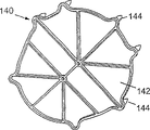
In Fig. 1,2 and 7, frame facet 30 and 32 comprises a corresponding opening 120,122 respectively, and the various parts of reel assembly are packed into by this opening.Frame facet 30 also comprises integrally formed wall 124, and this wall constitutes a spring cup or a cavity, and constitutes the part of spring housing 126.The shape of this wall 140 is roughly rounded.Be formed on the frame facet 30, in the wall 124 be a spring holding element 127 that is used to engage the outer end 128 of back-roll (rewind) spring 130 (as shown in Figure 8).This spring holding element 127 also is provided with at interval with wall 124, shown in the label in Fig. 1 and 8 129, so that spring therefrom passes through.Fig. 8 shows the planar view of frame facet 30, wall 124 and spring 130, and the outer end 128 of its medi-spring is contained in the spring holding element 127.One spring axostylus axostyle (arbor) 337 is connected in the inner of spring 130.
Wall 124 is formed with around what this wall 124 distributed and a plurality of first is press-fitted fastening feature portion 132.These first are press-fitted feature portion and have integrally formed path hole, and these pore volumes are received the coupling finger 144 of spring compressor cover piece 140.
Spring compressor cover piece 140 has been shown among Fig. 9 a and the 9b.It is suitably in place on the wall 124 of framework 22 that Fig. 7 shows this cap member 140.Because the cause at overlapping junction surface 125 can be improved the airtight quality between cap member and the wall 124.Frame material about 20, the high coefficient of curvature of 700Mpa (drying when molded) can improve leak free stability, and prevents constant outside caused distortion of pressure and distortion that reason back-roll spring 130 is produced on wall 124.This spring compressor cover piece comprise have a plurality ofly be press-fitted feature portion, such as sheet material, body or the cap body portion 142 of a substantially flat of finger 144.Though at length do not illustrate among the figure, the cross-sectional plane of each finger is trilobal.Finger 144 wherein each is inserted in the corresponding snapping feature portion 132 be connected so that spring compressor cover piece 140 is press-fitted with wall 124.
As mentioned above, side 32 comprises an opening 122.In the illustrated embodiment, the diameter of this opening 122 is greater than the diameter of opening 120.Opening 120 and 122 relative size will be along with the variations of the feature portion of reel assembly and are changed.Frame facet 32 comprises a rising edge 150 that can prevent that locking wheel (as shown in figure 13) and associated components from rubbing on smooth frame facet 32 on its outside face 121 and around opening 122.The inside face 123 of frame facet 32 comprises a wall section 151a around opening 122, one and diagonally extending, and this wall section provides one to be used for closely the fixer (stand-off) of the flange (but Fig. 7 is not shown) of retractor spool at interval.The inside face 123 of wall side 30 comprises a similar wall section 151b around opening 120.Edge 150 reduced and locking wheel between friction.Shown in Fig. 2 and 7, side 32 is formed with a whole wall 170 that extends of a part that constitutes mechanism's housing 190.This wall 170 also comprises and is similar to parts 132, is used for receiving member 172 that mechanism's cap member 180 is fixed thereon.Shown in Figure 10 a, 10b and 7, this mechanism's cap member 180 comprises a sheet material or body part 182 and all outstanding finger 184.This sheet material 182 and wall 170 form an overlapping junction surface 188, and it can prevent that dust or other material from entering into by cap member 180 and wall 170 formed mechanism side housings 190.This cap member 180 is made by sound-absorbing material, such as polypropylene or similar material.
Frame facet 32 comprises the recess 200 near the bottom of wall 170.Outward extending from this recess 200 is an available small tabs 202.On this recess, do not establish any through hole, enter into retractor so that prevent dirt.Recess 200 holds the part (not shown among Fig. 2) of vehicle inertia sensor.If use, tab 202 plays the effect of a block, and it adjoins the part of vehicle sensors housing, and prevents this housing shifted laterally.The wall 170 of contiguous recess 200 comprises two groove 204a and 204b (as shown in Figure 2), and the projection of the shape complementarity on these two grooves and the inertial sensor is complementary, and puts in place so that this sensor can slide in wall 170.In case wall 170 is covered by cap member 190, can only enter housing 190 by opening 122.This cap member gently is pressed on the vehicle sensors housing, so that it is held in place.This class formation that combines with mechanism housing cap member 180 reduces to minimum with the opening in the framework of proximity sense, thus sensor is isolated from the outside.
Graphic retractor 20 comprises an one-sided lockout mechanism.The present invention also can use in the bilateral locking mode, wherein adopts two locking wheels, and these two locking wheels are positioned on the relative both sides of framework, the inside face of contiguous usually frame facet, near opening 120,122.In order to lock retractor, adopt a rotating locking pawl, this ratchet moves to the gear teeth of locking wheel and contacts.As be known in the art, locking pawl rotates around a pin.U.S. Patent number 5,904,371, disclosed wherein a kind of ratchet and lockout mechanism in U.S. Patent number 5,511,741 or the U.S. Patent number 4,564,154.In the present invention, the Unitarily molded parts that become side 32 of the cylindrical pin shown in Fig. 2 and 11a.This pin has a substrate 210a, and the diameter of this substrate is greater than top cylindrical part 210b.This pin is designed to: can respond the size of the latching force that is produced and specially crooked in determining the collision process of energy level.
Figure 11 a is the another kind of block diagram of framework 22, and it also shows the locking pawl 220 on the pin 210.This locking pawl 220 as shown in the figure with the gear teeth 232 locking meshes of locking wheel 230.Retractor 20 comprises a cam type mechanism, and such as known rotatable locking ring 310, this cam mechanism moves to locking pawl 220 with locking wheel 230 from a freedom or unlocked position and is meshed.This locking pawl 220 can comprise a cam follower pin 231.Locking ring rotates around a retractor shaft portion under belt strap sensor or vehicle sensors influence in a known way.The locking cup comprises the cam of the form of common employing cam path, so that hold cam pin 231.Along with locking ring rotates, it moves locking pawl, so that the tooth mesh and the disengaging of itself and locking wheel 230.In retractor of the present invention, also can adopt other lockout mechanism.As shown in the figure, locking pawl 220 comprises two the locking teeth 222a and the 222b of wherein two gear teeth of the gear teeth 232 of engaging lock fixed wheel.So antagonistic force is just absorbed by two groups (rather than one group) coupling tooth.Though pawl teeth is designed to mesh simultaneously the locking teeth of coupling,, then may not can take place to mate simultaneously if the production tolerance who is adopted (tolerance) scope is wide.In these cases, one of them tooth will mesh, and may cause damaging.In another embodiment of the present invention, the body 223 of locking pawl is formed with a recess 225 (shown in Figure 11 b), and this recess can make pawl body crooked under the effect of load.Cause lower detent tooth 222b will initial assault locking wheel if constitute the production tolerance of framework, locking pawl and locking wheel, then after this initial locking mesh phenomenon takes place, locking pawl 220 is slight curving, and another tooth 222a is meshed with another tooth of locking wheel.This design has been guaranteed: when retractor is in crash scenario, two locking teeths of locking pawl will mesh.A benefit of this kind structure is that ratchet can be made by the lower cost materials such as zine pressure casting.
Locking pawl 220 comprises and is used as axle bush and around the circular port of the substrate 210a of pin 210.
The geometric configuration of locking pawl and locking wheel is designed to: when locking pawl is meshed with locking teeth, shown in Figure 11 a, all components of the antagonistic force that is produced in condensation course will be arranged in the whole zone that is made of arrow 240.
Framework 22 also comprises integrally formed ratchet and pin supporting device 250.This supporting device 250 comprises integrally formed Crossware or pillar 252, shown in Fig. 1,3,5b and 11a.Pillar 252 is formed on the inboard of pillar or Crossware 46, and connects side 30,32.This pillar 252 comprises 32 extremity pieces 254 that stretch out from the side.This mechanism 250 also comprises a curvilinear figure supporting member 256.One end 256a of this curvilinear figure supporting member 256 extends from the inboard of wall 170, so that the increased intensity and the sharing part of the load are provided.The other end of this curvilinear figure supporting member 256 or side 256b vertical extent pass the extension extremity piece 254 of pillar 252.
When retractor was locked, ratchet and locking wheel were taked the orientation shown in Figure 11 a.When power increases to a confirmable energy level when above, they tend to make pin 10 to distort, and the bottom of ratchet are moved to the curvilinear figure part 256 of supporting device 250 contact.So these reaction load or power are passed to the protrusion end 254 of pillar 252, are passed to pillar 252 thus, and are assigned on frame facet 30 and 32.Like this, plastic frame just can absorb the power that is produced by collision.
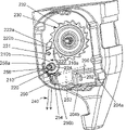
Figure 12 shows the vehicle inertia sensor 270 in the recess 200 that is contained in groove 204a, 204b and framework 22.This sensor 270 comprises the housing 272 with two masts or protruding 274a and 274b.Each projection comprises a neck or narrow 276 and an end.Each mast is contained among corresponding groove 204a, the 204b.Sensor 270 comprises the area supported 277 of the lower end 278 that holds inertial mass 279.The top 280 of inertial mass 279 is indents, and it holds the extendible portion 282a that responds to ratchet 282.This ratchet 282 is pivotally mounted on the supporting member 283, and this supporting member can be the extendible portion of housing 272, such as parallel alar part 273.In some was installed, ratchet 282 can be configured to make it to contact with a tooth of ratchet-gear wheel, and in this case, the shape of the end of ratchet is made dentation, so that the tooth of engagement ratchet-gear wheel.As shown in the figure, retractor 20 comprises second ratchet 290 of being located at ratchet 282 tops.This ratchet 290 comprises a tooth 292.As shown in the figure, inertial mass is a kind of humanoid inertial mass on one's feet.When vehicle encounters exceeds the deceleration of predetermined restriction, humanoid inertial mass overturning on one's feet, and the tooth of sensor pawl 282 is risen, so that for example being moved to, ratchet 290 contacts with the ratchet-gear wheel of belt strap sensor or locking ring.Moving of this action starting locking cup, however make locking pawl move to tooth 232 locking meshes with locking wheel 230.
Figure 13 is the spool of the retractor that supported by framework 22 and the cross sectional drawing of Shaft assembly 300.Figure 13 also shows roughly the same framework among its orientation and Fig. 7.This assembly 300 comprises by total by the represented spool that axis mechanism supported 302 of label 304.In this embodiment, this axis mechanism 304 comprises a locking wheel sub-component 310, and this sub-component comprises the ducted body 312 that wherein has spline wedge 314.One large-diameter portion divides 316 to be bearing on the opening or axle bush 122 of framework, and locking wheel 230 comprises a plurality of locking teeths 232 as mentioned above.This locking wheel 230 comprises that one is provided with the axis of a cylinder 305 of spline wedge, and toothed ratchet-gear wheel 306 is fixed on this axis of a cylinder by a pin 308.This axis of a cylinder comprises an aperture 305a, and this aperture holds and is used in a known way the pin 308 that all parts with the belt strap sensor are fixed together.The various toothed members 309 of belt strap sensor are contained in ratchet-gear wheel 306 in a known way.Locking ring 310 can rotate around axis of a cylinder 305.In this illustrated embodiment, axis mechanism 304 also can be formed by an available bar 320 of turning round.This is turned round bar and has first end 324, and this first end has a plurality of spline wedges 326 of the spline wedge 314 of engaging lock fixed wheel sub-component 310.Turn round bar 320 and comprise a centre portion 330 and second end 333.This second end 333 is formed with the spline wedge 334 that meshes the spline wedge 336 in the hollow hole 337 that is formed on spool 302.Locking wheel sub-component 310 together rotates with the end 324 of turning round bar, and spool 302 moves rotationally with the end 333 of turning round bar simultaneously.This is turned round bar 320 and can be replaced by not submissive metal shaft part.In this case, this not submissive metal shaft part can form the integral part as locking wheel sub-component 310.The outside of body 312 also can be formed with the spline wedge, so that provide extra supporting to spool 302.
In fitting process, spool 302 is inserted by the open top of framework, then will wherein be inserted with the locking wheel sub-component 310 of turning round bar and be inserted in the hole 337 then by opening 122.This end 332 of turning round bar is contained among the spring axostylus axostyle 337a, and this spring axostylus axostyle is arranged in the opening 120 of framework, and is fixed on the spring 130.
As shown in Figure 8, terminal 333 have two recess 340a and 340b, are contained in these two recesses around the protruding 341a of the formed coupling of cup-shaped inner fovea part and the 341b of spring axostylus axostyle.As shown in figure 13, spring axostylus axostyle 337 comprises at least one groove 342, in order to hold the inner of rewinding spring 130.One section seat safety belt strap 350 is wound on the spool 302.A folded part or a little pin that the utilization of one end (not shown) of this belt strap is wedged in the groove 352 are fixed in the groove 352 of spool.This spool 302 can comprise flange 302a and the 302b that radially extends, and when being wound on the spool with convenient belt strap 390, guides this belt strap.
Embodiment shown in Figure 13 adopts one to turn round bar.This is turned round bar and represents a class energy absorbing or dissipation safety band rewinder, and this retractor comprises one or morely turns round bar and one or more distortion axle bush, and the seat safety belt strap with variable elongation characteristics.These energy absorbing retractors are shared such performance, and promptly the antagonistic force at spool place is limited by the energy absorbing energy level of turning round bar, distortion axle bush or variable elongation belt strap.The energy level of the power of impact on locking pawl also is restricted similarly.For example, for a representative type was turned round the bar retractor, the energy level of power should be about 4-12Kn.Though in preferred embodiment of the present invention, plastic frame will together use with the energy absorption mechanism of some kind, because causes such as their caused load limit factors, the application of plastic frame might not be like this.The present invention can together use with these energy absorption mechanism or without this type of energy absorption mechanism.Turning round bar can be replaced by a traditional axle.
Figure 14 shows another embodiment of the present invention, wherein has the mechanism's wall 170 that is formed with inwall 170a and outer wall 170b, constitutes a space 171 between inwall and outer wall.Not necessarily want continuously in this space 171, but can be divided into plurality of sections by the part in the fastener 132.Outer wall 170b can intactly seal inwall and fastener 132, and can be by segmentation or not segmentation or unlimited fully, so that a continual space 171 is provided.As previously mentioned, wall or, in this case, inner and outer wall is all airtight by 190 of mechanism's cap member.Space 171 has reduced the energy level by the noise that all movable parts sent of vehicle sensors and belt strap sensor.By using sound-absorbing material 173 filling spaces 171 such as light foam material or intensive thixotropic materials can further reduce noise.The body of cap member 190 can be formed into hollow form, and is filled with sound-absorbing material, so that further improve the noise reduction quality of retractor.
In Figure 15, hook-shaped bottom fabricated section 160b is formed into an opening 160b.One threaded fasteners is fixed on the bottom in space on the installation surface 90.
The present invention has reduced number of components, has increased dimensional control, and has reduced the change in size in the retractor, thereby has improved Performance And Reliability.By utilizing one and forming the various feature portion of the parts of framework simultaneously, can control the orientation of each member more accurately.In addition,, can no longer need manufacturing process is taked the mistake proofing measure by forming retractor with many integrally formed elements, this be because these feature portions can be in integrally formed framework the cause of orientation automatically and suitably.