CN1237294C - Device for controlling flowing media - Google Patents
Device for controlling flowing media Download PDFInfo
- Publication number
- CN1237294C CN1237294C CNB008063702A CN00806370A CN1237294C CN 1237294 C CN1237294 C CN 1237294C CN B008063702 A CNB008063702 A CN B008063702A CN 00806370 A CN00806370 A CN 00806370A CN 1237294 C CN1237294 C CN 1237294C
- Authority
- CN
- China
- Prior art keywords
- cone
- valve disc
- gate valve
- axis
- worktable
- Prior art date
- Legal status (The legal status is an assumption and is not a legal conclusion. Google has not performed a legal analysis and makes no representation as to the accuracy of the status listed.)
- Expired - Fee Related
Links
- 238000007789 sealing Methods 0.000 claims abstract description 84
- 238000005520 cutting process Methods 0.000 claims description 19
- 238000000034 method Methods 0.000 claims description 18
- 238000012545 processing Methods 0.000 claims description 16
- 239000000463 material Substances 0.000 claims description 14
- 238000004519 manufacturing process Methods 0.000 claims description 9
- 239000012530 fluid Substances 0.000 claims description 5
- 230000000694 effects Effects 0.000 description 13
- 238000006243 chemical reaction Methods 0.000 description 5
- 230000033001 locomotion Effects 0.000 description 5
- 238000010586 diagram Methods 0.000 description 4
- 238000006073 displacement reaction Methods 0.000 description 4
- 238000005452 bending Methods 0.000 description 3
- 238000013461 design Methods 0.000 description 3
- 230000011218 segmentation Effects 0.000 description 3
- 230000009977 dual effect Effects 0.000 description 2
- 230000002349 favourable effect Effects 0.000 description 2
- 230000005484 gravity Effects 0.000 description 2
- 230000002045 lasting effect Effects 0.000 description 2
- 238000003801 milling Methods 0.000 description 2
- 241000040710 Chela Species 0.000 description 1
- 239000000654 additive Substances 0.000 description 1
- 230000000996 additive effect Effects 0.000 description 1
- 238000004364 calculation method Methods 0.000 description 1
- 230000006835 compression Effects 0.000 description 1
- 238000007906 compression Methods 0.000 description 1
- 238000000205 computational method Methods 0.000 description 1
- 238000005336 cracking Methods 0.000 description 1
- 238000009826 distribution Methods 0.000 description 1
- 229910001651 emery Inorganic materials 0.000 description 1
- 238000007667 floating Methods 0.000 description 1
- 231100001261 hazardous Toxicity 0.000 description 1
- 230000010354 integration Effects 0.000 description 1
- 230000004807 localization Effects 0.000 description 1
- 238000003754 machining Methods 0.000 description 1
- 238000012423 maintenance Methods 0.000 description 1
- 238000012856 packing Methods 0.000 description 1
- 238000003672 processing method Methods 0.000 description 1
- 230000001737 promoting effect Effects 0.000 description 1
- 230000000630 rising effect Effects 0.000 description 1
- 238000000926 separation method Methods 0.000 description 1
- 230000003068 static effect Effects 0.000 description 1
- 238000006467 substitution reaction Methods 0.000 description 1
- 238000013519 translation Methods 0.000 description 1
- XLYOFNOQVPJJNP-UHFFFAOYSA-N water Substances O XLYOFNOQVPJJNP-UHFFFAOYSA-N 0.000 description 1
Images


Classifications
-
- F—MECHANICAL ENGINEERING; LIGHTING; HEATING; WEAPONS; BLASTING
- F16—ENGINEERING ELEMENTS AND UNITS; GENERAL MEASURES FOR PRODUCING AND MAINTAINING EFFECTIVE FUNCTIONING OF MACHINES OR INSTALLATIONS; THERMAL INSULATION IN GENERAL
- F16K—VALVES; TAPS; COCKS; ACTUATING-FLOATS; DEVICES FOR VENTING OR AERATING
- F16K1/00—Lift valves or globe valves, i.e. cut-off apparatus with closure members having at least a component of their opening and closing motion perpendicular to the closing faces
- F16K1/16—Lift valves or globe valves, i.e. cut-off apparatus with closure members having at least a component of their opening and closing motion perpendicular to the closing faces with pivoted closure-members
- F16K1/18—Lift valves or globe valves, i.e. cut-off apparatus with closure members having at least a component of their opening and closing motion perpendicular to the closing faces with pivoted closure-members with pivoted discs or flaps
- F16K1/22—Lift valves or globe valves, i.e. cut-off apparatus with closure members having at least a component of their opening and closing motion perpendicular to the closing faces with pivoted closure-members with pivoted discs or flaps with axis of rotation crossing the valve member, e.g. butterfly valves
- F16K1/222—Shaping of the valve member
-
- F—MECHANICAL ENGINEERING; LIGHTING; HEATING; WEAPONS; BLASTING
- F16—ENGINEERING ELEMENTS AND UNITS; GENERAL MEASURES FOR PRODUCING AND MAINTAINING EFFECTIVE FUNCTIONING OF MACHINES OR INSTALLATIONS; THERMAL INSULATION IN GENERAL
- F16L—PIPES; JOINTS OR FITTINGS FOR PIPES; SUPPORTS FOR PIPES, CABLES OR PROTECTIVE TUBING; MEANS FOR THERMAL INSULATION IN GENERAL
- F16L55/00—Devices or appurtenances for use in, or in connection with, pipes or pipe systems
- F16L55/10—Means for stopping flow from or in pipes or hoses
Abstract
The invention relates to a shut-off flap for pipelines, with a flap disc which is pivotable relative to an axis of rotation in a housing and which, in the sealing position, closes the throughflow through the housing in the region of a seal. The particular feature of the shut-off valve according to the invention is that the flap disc (32) is self-closing in both flow directions.
Description
Affiliated field
The present invention relates to a kind of pressure chamber that is used for, container or pipeline by gate valve particularly, comprise a valve disc that can be positioned at the rotation axis swing of housing relatively, this valve disc is on sealing station, in the scope of seal arrangement, from two opposite flow directions, will end by the fluid of described housing, described valve disc is eccentric, promptly have one and be arranged on seal arrangement center line rotation axis in addition, and this rotation axis particularly extends by the main axis by gate valve.
Background technique
In the pipeline of transport flow medium, fluid ends by valve, guiding valve or gate valve.Gate valve is because its structure length is obviously short and small, so preferably adopted.
The simplest structure of gate valve is to have a rotatingshaft of arranging along the valve disc center line.Known structural type also has eccentric, and wherein rotatingshaft and valve disc are spaced apart.This structure can be improved the sealing function of valve disc usually, does not interrupt because the seal arrangement of valve disc can not be extended the rotatingshaft of enclosure interior.Described rotatingshaft is usually located at the front or the back of valve disc.Rotation axis or rotatingshaft also can be positioned at the central authorities of valve disc front in addition, and crossing with the main shaft by gate valve, thereby also crossing with the main axis of pipeline usually.
So-called two eccentric gate valve is arranged in addition.Except described off-centre, rotation axis or rotatingshaft also are arranged on outside the main axis in the type, that is to say, apart from main axis a very little distance are arranged.This structure can realize closing automatically effect, perhaps realizes positive closing on a flow direction.Then can produce a disadvantageous lasting cracking pressure on another flow direction, so also a lasting and very high closing force must must be arranged, this closing force has corresponding very high driving moment.Particularly under the pipeline pressure condition with higher, can produce leakage point if things go on like this, thereby make and ductedly can't realize non-hazardous operation by side.
Summary of the invention
From above background, task of the present invention is that a kind of gate valve that ends that improves sealing effect that has is provided.Another task is to use littler driving moment just.
For this reason, the invention provides a kind of pressure chamber that is used for, container or pipeline by gate valve particularly, comprise a valve disc that can be positioned at the rotation axis swing of housing relatively, this valve disc can be on sealing station, in the scope of seal arrangement, from two opposite flow directions, will end by the fluid of described housing, described valve disc is eccentric, promptly has a rotation axis of not putting beyond the seal arrangement center line, and this rotation axis particularly extends by the main axis by gate valve, it is characterized in that, the position around sealing surface DF of described seal arrangement is as follows: the described sealing surface DF of a. is a conical surface portion section, its bus is determined sealing surface DF with respect to the angle by the gate valve main axis, b. described bus intersects at vertex of a cone place, its position is determined in the following manner: b1. seal arrangement center line and main axis intersect vertically, b2. the relative seal arrangement center line of rotation axis (run-on point 46) separates a distance (off-centre) layout, particularly be positioned on the main axis, and extend perpendicular to seal arrangement center line and main axis, b3. determine an O-ring with rotation axis (run-on point 46) as the center of circle, its diameter is less than the nominal width DN of pipeline, perhaps less than the effective internal diameter that is positioned at by gate valve inside, the intersection point of b4. described O-ring and seal arrangement center line is denoted as A and C, O-ring is denoted as B with the intersection point of straight line by A and run-on point, wherein B is positioned at the opposite of the some A that crosses center line, b5. described O-ring is denoted as S0 at the tangent line of an A and the intersection point of straight line B-C, b6. line segment A-B passes along tangent line, overlaps with S0 up to A; B after the passing then represents vertex of a cone S1, and perhaps line segment A-S0 section along the line A-B passes, and overlaps with B up to A; S0 after the passing then represents vertex of a cone S1.
A kind of improvement of the present invention makes valve disc close automatically on two flow directions.That is to say that the last section of closing movement obtains promoting by the synthetic work pressure that acts on the valve disc, and has nothing to do with flow direction.In the simplest situation, this effect can realize that it is on operating position by the valve disc that central authorities are provided with, on two flow directions, the area of rotation axis both sides varies in size, and wherein bigger area is pressed diagonal with respect to rotation axis and arranged that less area also is like this.This device that can not realize of seeming can be by the specific thicknesses of valve disc and in the scope of side, from rotation axis apart from maximum, the obtaining of inclination around sealing surface.The side of seal arrangement has one along the main axis direction with along diametric spatial depth.Can realize two different area relations on the flow direction along the diametric degree of depth exactly.In the face of valve disc one side of a flow direction, be divided into left surface and right surface by rotatingshaft.For producing closing force, must there be difference on this surface.For a valve disc of observing from flow direction, it turns right when closing, if the left surface just can produce a positive closing effect greater than right surface.Same condition also is applicable to the opposite side of valve disc on another flow direction.Can also pass through the laterally inclined mode of sealing surface, make the described left valve disc surface of a side that is positioned at greater than the right valve disc surface that is positioned at opposite side (being the surface on opposite).
The preferred annular seal that adopts particularly is arranged on the Sealing on the valve disc circumference, it when valve disc is closed, can be pressed on around sealing surface on.Wherein can produce a belt stress, pressure is evenly distributed on the circumference, thereby produce good ring packing effect.
The inclination of described sealing surface can be to some extent on the opposed edges of side, and perhaps integral loop forms around ground, to obtain a kind of so-called valve seat awl or taper.Described valve disc also can adopt eccentric structure, and promptly its rotation axis is positioned at beyond valve disc or the affiliated seal arrangement center line.Also can be implemented in two positive closings on the flow direction on this structure principle.
A kind of favourable structure is that rotation axis is positioned on the main axis or with it and intersects.Can simplify structure like this by gate valve.Power that is produced and moment almost are symmetrical.
When using the structure of valve seat awl, preferably adopt bigger valve seat cone angle, the frictional force when reducing closure.The valve seat awl is to determine by the position of the position of valve seat axis of cone line or cone axis and the vertex of a cone.The selection or the calculation method of valve seat awl are to occur the jammed situation of valve disc in sealing area.Favourable structure of the present invention be a kind of valve seat awl with geometry in particular as mentioned above by gate valve.
Here the significant starting point of institute's foundation is, the vertex of a cone and rotating center are positioned at the not homonymy of seal arrangement center line.And the closing direction of valve disc produces as follows, is positioned at the opposite of the vertex of a cone of crossing main axis when promptly valve disc is on its open position.
As described in first section in this specification, eccentric or two eccentric structure forms are known.The structural type that gate valve can be realized a kind of off-centre of ending with feature of the present invention, rotation axis wherein particularly intersects with main axis, the action of valve disc can realize on two sense of rotation, and for two its driving moments of flow direction be significantly smaller than known up to now all by gate valve.This also is applicable to the valve disc structure that has around sealing surface, and for example having one almost is arbitrarily thin around spring ring on flow direction.Though this valve disc no longer can auto-closing, yet only needs very little holding torque valve disc can be remained on the position of closing.Open the driving moment of valve disc, equally also be significantly smaller than known by gate valve.The size of the drive unit of valve disc is also dwindled widely than existing device.This is particularly conducive to the gate valve of fast opening and closing.
A reason of being convenient to open by gate valve is, used the floating spring circle as on the valve disc around Sealing.This spring ring can be placed in the interior conical valve seat around sealing surface of gate valve casing.Spring ring is pressed in the conical valve seat of conical surface more muchly, for example be pressed into by the pressure difference of valve disc both sides or by driving moment, then the reaction force that produces owing to the pressure spring circle (force compensating) or the moment of reaction are just big more, and this reaction force or moment make valve disc be easy to open.The selection mode of the angle of conical surface is, can not produce stuck or do not have self-locking.
The invention still further relates to the method for different manufacturings at last by gate valve.Specifically relate to the processing of the sealing surface on valve disc and the housing.Described in practice seal arrangement is made of the corresponding Sealing around on sealing surface and other each parts that is arranged on valve disc or the housing.The processing and the sealing surface of described Sealing are similar.Described Sealing preferably is set on valve disc.
On the one hand, for on described housing, processing the geometrical shape of seal arrangement, housing is fixed on the rotating worktable, its orientation type on worktable is, the rotation axis of worktable is the cone axis of sealing surface simultaneously, and remove the material of the housing in the sealing surface scope, worktable rotation simultaneously along cone generatrices with a rotary cutter with processing line.
On the other hand, for on described valve disc, processing the geometrical shape of seal arrangement, valve disc is fixed on the rotating worktable, its orientation type on worktable is, the rotation axis of worktable is the cone axis of sealing surface simultaneously, and remove the material of valve disc with a rotary cutter with processing line along cone generatrices, perhaps remove the sealing member material that has on the valve disc, worktable rotation simultaneously.
And on the one hand, for on described housing, processing the geometrical shape of seal arrangement, housing is fixed on the rotating worktable, perhaps be fixed on the rotating machine with a chuck indirectly, its orientation type is, the rotation axis of worktable or working machine tool is the cone axis of sealing surface simultaneously, and remove the material of housing with a cutting tool with cutting edge by the rotation of worktable or working machine tool, and described cutting tool with cutting edge moves along cone generatrices.
On the other hand, for on described valve disc, processing the geometrical shape of seal arrangement, valve disc is fixed on the rotating worktable, perhaps be fixed on the working machine tool with a chuck indirectly, its orientation type is, the rotation axis of worktable or working machine tool is the cone axis of sealing surface simultaneously, and remove the material of valve disc by the rotation of worktable or working machine tool with a cutting tool with cutting edge, perhaps remove the sealing member material on the valve disc, and described cutting tool with cutting edge is to move along cone generatrices towards the direction of vertex of a cone S0 or return.
Brief description of drawings
The present invention is further illustrated for contrast accompanying drawing illustrated embodiment below.
Fig. 1 represents the sectional view of a center by gate valve,
Fig. 2 represents the sectional view of an off-centre by gate valve, and has marked a specific flow direction,
Fig. 3 represents the gate valve that ends shown in Figure 2, has opposite flow direction,
Fig. 4 to Fig. 6 represents three different views by gate valve, i.e. the plan view of a streamwise, and a vertical sectional view and a horizontal cross, the latter is similar to Fig. 1 to Fig. 3,
Fig. 7 represents a horizontal cross by gate valve, comprises the auxiliary line that is used for determining valve seat awl or seal arrangement geometrical shape,
Fig. 8 represents the diagrammatic sketch corresponding to Fig. 7, and has other auxiliary line,
An enlarged view of Fig. 9 presentation graphs 8,
Figure 10 presentation function general view, promptly one is ended the horizontal cross of gate valve and the revolving table of a numerical control machine tool (CNC lathe),
Figure 11 represents that the housing by gate valve shown in Figure 10 is clamped on the revolving table,
Figure 12 represents that valve disc shown in Figure 10 is clamped on the revolving table,
Figure 13 represents the similar diagrammatic sketch with Figure 10, but has used another kind of different slightly processing,
Figure 14 representation class is similar to the diagrammatic sketch of Figure 11,
Figure 15 table is similar to the diagrammatic sketch of Figure 12,
Figure 16 to Figure 19 is expressed as the geometric diagram of determining required size on the structure and doing,
Figure 20 table by gate valve when closure, around the seal ring scope in the active force that occurs,
Figure 21 represents the cross section of seal ring,
Figure 22 represents the another kind of diagram of the active force that occurs among Figure 20,
Figure 23 is corresponding to Figure 21,
Figure 24 is similar to Fig. 8 and Figure 16, is used for the computational methods of vertex of a cone S1 and seal valve seat elliptical shape so that another kind to be described,
Figure 25 represents a projection that is used to further specify elliptical shape,
Figure 26 represents the fluid cross-section figure in gate valve, is used to illustrate the power and the moment that are occurred,
Figure 27 representation class is similar to the diagrammatic sketch of Fig. 9 and Figure 17, is used to further specify elliptical shape.
Preferred embodiment
At first the some important basic conception by gate valve 10 of the present invention is described in conjunction with Fig. 1.Valve disc 11 is arranged in the housing 12 with center rotating shaft line 13.Do not draw among the figure and be positioned at the pipeline at the place ahead and rear.
A sealing seat that is positioned at housing 12 represents with label 14, it have around sealing surface 15.A corresponding sealing surface that is positioned at valve disc 11 scopes is represented with label 16.In practice, also a plurality of diaphragm seals can be set here or in housing.
Described main axis 17 by gate valve 10 is parallel to flow direction 18,19 and extends, and in the present embodiment by rotation axis 13.Say that exactly main axis 17 passes through a plane center of gravity of valve disc 11 as the axis of streamwise.Usually main axis also is a conduit axis.
In the present embodiment, the direction along arrow 23 when valve disc 11 is opened turns right, and the direction along arrow 24 turns left when closure.
Structure by gate valve 10 can allow valve disc 11 forced closed on two flow directions 18,19.When flow direction was arrow 18, valve disc right side 25 was stressed, and under 19 effects of opposite flow direction, valve disc left side 26 is stressed.The both sides 25,26 of valve disc can be divided into the side surface 27,28 and 29,30 that is oppositely arranged, and division wherein is that the position by main axis 17 produces.Be that closing force is because the surfaces 29 of different sizes and 30 produce under 18 the situation at flow direction.Side surface 29 since the cause of the sealing surface 16 that is in tilted layout greater than side surface 30.This relation is just opposite on the surface 26 that is positioned at the opposite.Under opposite flow direction 19 effect, also can be above it owing to the surfaces 27 of different sizes and 28 and correspondingly produce closing force.
Above-described pass ties up to can be from slightly different observing by gate valve 31 of structure once more among Fig. 2 and Fig. 3.Here different with Fig. 1 is direction of rotation.Valve disc 32 turns right when closing, and sees arrow 33, turns left during unlatching, sees arrow 34.Different flow directions represents that with arrow 35 and 36 housing represents that with label 37 main axis represents that with label 38 the seal arrangement center line is represented with label 39.40 usefulness A1 and A2 represent that 41 usefulness A3 and A4 represent in the left side to the label of the side surface of different sizes on the right side.Same with embodiment illustrated in fig. 1 the same, the closing force here also occurs on two flow directions.
Different with Fig. 1 is, the valve disc 11 among Fig. 2 and Fig. 3 has a so-called conical valve seat, has on the housing 37 mutually the diaphragm seal 44 of corresponding layout on the sealing surface 42,43 aimed at taper and valve disc 32 circumference.The imaginary line stretcher of described sealing surface 42,43 on figure plane intersects at unillustrated valve disc 32 left sides among the figure, and the top of main axis 38, thereby constitutes a taper.Can produce in a circumferential direction one around sealing surface DF, it is a conical surface portion section.An oblique line 45 that passes seal arrangement center line 39 and main axis 38 is expressed the axis of this cone.
With by gate valve 10 different be, by gate valve 31 a little (dual) off-centre is arranged, its rotating center 46 abuts against main axis 38 next doors.Throw of eccentric is that rotating center 46 to the distance of main axis 38 will be selected very for a short time, thereby because the distribution of area can produce closing force on two flow directions.In the present embodiment, this distance is less than half of the sealing surface degree of depth TD of diaphragm seal 44.Wherein TD sees shown in Figure 1 along the direction perpendicular to the seal arrangement center line 39 of main axis 38.
What Fig. 4 to Fig. 6 represented is a three-view diagram by the gate valve practical structures.What relate to also is a kind of structure eccentric gate valve identical with Fig. 2 and Fig. 3.So adopted identical label.The bearing 50,51. that can see rotatingshaft 47, pipe flange 48,49 in addition and be used for rotatingshaft 47 can be clear that at Fig. 5, and sealing surface has only very little inclination in top circumference area 52 or lower circumference district 53 relative main axiss 38 when rotatingshaft 47 is vertical.Between the side circumference area of this circumference area and band sealing surface 42,43, must adopt to seamlessly transit.In fact zone 52,53 also mutually structures in an angle, it is equivalent to Fig. 2 and " conical valve seat " shown in Figure 3.
Contrast Fig. 7 to Fig. 9 is illustrated in more detail to the structure of " conical valve seat " and the angular dependence of sealing surface 42,43 or circumference area 52,53 below.Wherein end the structure of gate valve based on Fig. 4 to Fig. 6.So adopted identical label.
A pipeline to be closed has a nominal diameter DN.Valve disc 32 will have slightly little diameter certainly.In the present embodiment, this valve disc is different with Fig. 4 to Fig. 6 is to be center arrangement (only single off-centre because rotation axis is arranged on beyond the seal arrangement center line), and its rotating center 46 is by main axis 38.Main axis also is a conduit axis simultaneously.O-ring 55 is that the intersection point A by the seal arrangement center line 39 and the sealing surface 42,43 that must constitute forms around rotating center 56.In this process, diameter is known in the scope of sealing surface 42,43, can be used as initial conditions and uses.Required design only be that the taper of sealing surface is pointed to.
Straight line by rotating center 46 and intersection point A defines the intersection points B that is positioned at the opposite automatically.Be positioned at intersection point A opposite and, on O-ring 55, obtain an intersection point C along seal arrangement center line 39.
Can constitute auxiliary line i.e. the tangent line T1 of the O-ring 55 by some A and the straight line G1 by some B and C according to an A, B, C.This straight line T1 and G1 intersect at a S0.
By an A being overlapped line segment A-B translation with some S0 along tangent line T1, some B then defines a new some S1.From this S1, can draw by circular cone line K1 and the K2 of an A and C.Described circular cone line K1 and K2 define the scope (bus) of cone, and it defines the angle by the conical valve seat of gate valve 31 or sealing surface 42,43 simultaneously, and the angle that defines affiliated seal element on valve disc 32.
The result makes to produce one between a S1 and the main axis 17,38 apart from a, and it equals valve disc 32 radius r
K3 times.
Cone axis K
A Pass valve disc 32 from point of intersection S 1, and between an intersection point 56 of rotating center 46 and main axis 38 and seal arrangement center line 39.Described cone axis K
AThe position is gate valve obtains closure effect on two flow directions a supplementary condition.
In the drawings, housing 37 have around sealing surface, valve disc 32 has diaphragm seal 44.In fact this element also can exchange, and for example makes valve disc 32 have smooth sealing surface.
Following explanation with reference to Figure 10 to Figure 15 is seen in the manufacturing of sealing surface or diaphragm seal group and processing.Wherein valve disc 32 adopts single eccentric manner to arrange that its rotating center 46 is positioned on the main axis 38.
Figure 10 to Figure 12 expresses the manufacture method of valve seat awl.What wherein Figure 10 represented is the function overview, and valve disc 32 and housing 37 have drawn.In fact two parts can separately be made, and see Figure 11 and Figure 12.
Fig. 11 expression housing 37 clamps with an auxiliary device 60 on a specific angular orientation.Angle [alpha] is main axis 38 and cone axis K
AAngle.This axis also is the rotation axis D of following described rotary work-table 61 simultaneously
A
Processing is carried out on a so-called CNC milling machine center.Revolving table 61 usefulness B axles are represented.In course of working, around sealing surface the 42, the 43rd, the 62 pairs of housings 37 of cutter by high speed rotating process.Rotary work-table 61 is done relatively slow rotation simultaneously, and in conjunction with the axial motion of cutter 62 along arrow 66.Importantly cutter 62 will accurately be aimed at the cone generatrices of being calculated, and housing 37 will be realized accurate localization by auxiliary device 60 simultaneously.
As shown in figure 12, valve disc 32 has diaphragm seal 44.Its external diameter equally also must match with valve seat awl or taper bus.Valve disc 32 will be fixed on the rotary work-table 61 by another auxiliary device 67 for this reason, and processes housing 37 with cutter 62 according to aforementioned manner, but will process from the outside.Corresponding is that axis 65 is positioned at outside the taper bus (circular cone line K1, K2) therewith.Add the rotation of man-hour by worktable 61, observer's housing 37 and valve disc 32 will produce oscillating motion relatively.Spatially be positioned at the surface of the cone of being calculated around sealing surface.Because the cause of geometrical relationship, resulting sealing surface has elliptical shape.
Another kind of slightly different processing method sees that Figure 13 is to shown in Figure 15.Figure 13 expresses the general view of all parts as Figure 10.
Figure 14 represents the processing of housing 37.Different with Figure 11 is that a not rotary cutter 68 with cutting edge 69 is arranged here.Housing 37 also is fixed on the auxiliary device 60.The latter is clamped on the chela 70 of chuck.Add man-hour housing 37 and rotate, and cutter 68 only is parallel to cone generatrices along the direction of arrow and moves, and sees arrow 71 around cone axis KA (being rotation axis DA simultaneously).
The manufacturing of the profile in valve disc 32 scopes is processed equally from the outside, is similar to Figure 12.
Except the above manufacture method, also can adopt additive method, for example laser beam machining or water jet cutting.
Contrast Figure 16 to Figure 19 illustrates the calculating of design data below.Employed index and variable are distinguished by the above.Design to provide by the pendulum radius R of gate valve and rotation axis to sealing plane (WAU) apart from a.
R draws from the requirement to nominal width.A draws (material is selected, and pressure requires or the like) from static stiffness.Rotation axis passes through conduit axis.
Definition: R=line segment MU comprises line segment MV and MW certainly
A=line segment MA
Determining of structure required size:
Angle α determines:
Angle β determines:
Angle γ determines:
Equation (III)
Line segment UW determines:
By line segment W Ω determining to a Ω:


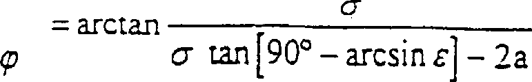
For carrying out the calculating of back, must determine the position of some φ:
By separation Ω, the right angle auxiliary triangle shape that φ and Γ constitute equates with the triangle area that some U, V and W constitute.
So have: line segment φ Γ=2a
Line segment Γ Ω=UW=2 UA (seeing equation IV)
Therefore line segment T φ is had:
Tφ= WΩ- φΓ= WΩ-2a
Equation (VI)
At this moment, the size of cone angle and position can be determined by following formula:
Equation (VII)
Angle η determines:

Equation (VIII)
So taper angle theta is:
Equation (IX)
The position of tap web is described with angle ρ:

Use the relation of running shaft apart from a and radius R: ε=a/R
Can obtain the representation of above equation (I) to a kind of simplification of (X):
In addition, if replace 2a tan[arccos (a/R) with symbol σ],
The following simplification that then can obtain equation I to X is expressed;
Equation (I) α=arccos ε
Equation (II) β=arcsin ε
Equation (III) γ=90 °-arcsin ε
Equation (IV) UW=σ
Equation (V) W Ω=σ tan[90 °-arcsin ε]
Equation (VI) T φ=σ tan[90 °-arcsin ε]-2a
Equation (VII)
Equation (VIII)

Equation (IX)

Equation X
Contrast Figure 20 to Figure 23 is illustrated the power when gate valve is closed below.Valve disc has the Sealing of diaphragm seal 44 shapes, sees Fig. 2 and Fig. 3.For simplicity, in Figure 20 to Figure 23, only express a unique spring ring 71.This spring ring can constitute the Sealing of valve disc separately, perhaps constitutes the diaphragm seal group with other thin seal rings.Below the Sealing of hypothesis valve disc does not adopt the shape of relative thin, thus only be provided with one around bearing or groove in the spring ring 71 that floats.
When gate valve is closed, spring ring 71 lean against gate valve casing around on the seal valve seat.Because the rotating closed motion shown in the arrow 72 has stronger pressure in side regions 73,74 effects, it is because the taper of seal valve seat produces, and is roughly suitable with the rising of clinoplain.
Do not have inside power effect in top circumference area 52 and lower circumference district 53 because spring ring 71 herein and rotation axis (rotating center 46) intersect.Correspondingly produced the pressure of outside effect of spring ring 71 as reaction force in this circumference area 52,53.So spring ring 71 is coupled to close seat automatically.The elasticity of the power that is produced by spring ring 71 is evenly distributed or is transmitted.Wherein importantly the arrangement of spring ring 71 will make it perpendicular to flow direction registration or bias motion can take place.
Figure 22 represents the diagram of the power that produced.Compressed circle 75 defines different power with the skew of its relative spring ring 71 external diameters.By the pressure maximum of external action to the spring ring 71, then mainly is the reaction force that therefrom produce in upper and lower circumference area 52,53 in side regions 73,74.This power yes outwardly the effect.
Contrast Figure 24 and Figure 25 are described the elliptical shape of valve disc or sealing seat below.As mentioned above, sealing seat, promptly in the gate valve casing 37 around sealing surface be have vertex of a cone S1 cone-part.Because vertex of a cone S1 is not on the main axis 38,, and has the shape of an ellipse so affiliated conic section and cone axis KA form an angular length that is not equal to 90 degree.So around sealing surface two diameters are arranged, be equivalent in the mathematics oval size commonly used, i.e. a major diameter 2a and a minor diameter 2b.Major diameter 2a wherein in Figure 24 corresponding to the line segment between the A to C.Minor diameter 2b is corresponding to the height of valve disc 32, and it is to be obtained by the straight line 76 perpendicular to cone axis KA by a p, and wherein this vertical line and main axis 38 intersect at the intersection point 56 of seal arrangement center line 39.Straight line 76 and the bus K1 of described cone and intersection point s and the t of K2 as can also be seen from Figure.Minor diameter 2b equates with distance along the some s to t of straight line 76.
As shown in figure 24, some S1 is positioned on the parallel lines 77 of main axis 38, and wherein the distance between parallel lines 77 and the main axis 38 equals the valve disc radius r
k3 times of (r
kDistance between=56 to C).The position of some S1 on parallel lines 77 is to obtain by the tangent line 78 of O-ring 55 at a B (or the some V among Figure 16 to 18).Therefore rotating center 46 is apart from seal arrangement center line 39 (by the offset of gate valve) far away more, and then the some S1 on the parallel lines 77 just gets over left towards the direction of seal arrangement center line 39 and moves.
Can draw elliptical shape according to Figure 25 around sealing surface.Cone with vertex of a cone Z and bus Z1, Z2 has a cone axis ZA, and it also is a cone angle simultaneously
 Angular bisector.The point H that half is highly located by cone and directly intersect at intersection point H1, H2 in conic section of cone axis ZA and bus Z1 and Z2.Affiliated inclination conic section marks with two-wire.This part is made of the segmentation D1 and the D2 of two equal in length, and both length is a.Some H between segmentation D1 and the D2 is not positioned on the cone axis, but separates a distance with the intersection point p of cone axis.Distance between some H and the p is the size of offset, and it can adopt oval computation rule to draw.Oval throw of eccentric accurately is
, and digital offset ε is ε=e/a.
According to the diverse location in beveled cone cross section, some H can have bigger or less distance apart from cone axis ZA.Wherein in Figure 25, there are some conic sections to draw from a ZS.Can find out the height of the ellipse of the conic section by a H in addition.This ellipse has height 2b, and it equals the distance between the H1 to H2.Some H among Figure 25 and p are corresponding to point 56 and p among Figure 24.Clear for representing, segmentation D1 and D2 have also drawn among the figure.
Characteristics by gate valve of the present invention are, adopt relatively thin spring ring or seal ring, so and the existing gate valve that ends compare, its control moment is less relatively.Theoretically, when seal ring is infinitely thin, but beginning is described and the active force of auto-closing or maintenance automatically will can not produce.Because gate valve adopts symplex structure, rotation axis to be positioned on the main axis 38=single offset, so the power that acts on threshold dish both sides by different pressure obtains balance.It is less relatively to be used for the required control moment of valve disc open and close.So the size of drive unit also can correspondingly reduce.
When gate valve was closed, because a little bending appears in the different pressures of valve disc both sides on valve disc, the maximum value of amount of bow appeared at half eminence certainly, is along the X-axis line in Figure 26.Because the layout of crooked and above-mentioned conical valve seat can make seal ring or spring ring 71 produce a lateral displacement.But this lateral displacement is minimum, only needs a little to increase required control moment.Contrast Figure 26 and resulting formula is illustrated perpendicular to the effective torque of closed valve disc after to spring ring 71 displacements below.This explanation also is applicable to thick seal ring or diaphragm seal group and thus in the different moments of valve disc double side acting.In following formula, have:
Wherein y=f (x) (XI)
Wherein y=f (x) (XII)
(XIII.)
(XIV.)
∑Mi=0=M
1-(M
2+ΔM) (XV.)
ΔM=M
1-M
2 (XVI.)
Wherein (0 °≤≤180 °) and
And
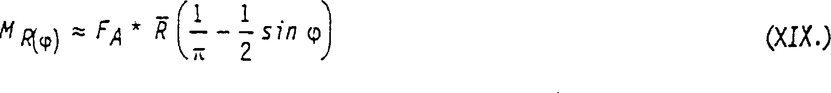
Equation (XIX.) has been described the general type of the bending moment that produces among Figure 20 on spring ring 71 circumference, its relative horizontal angle with radius R is relevant, this bending moment be since around the conical valve seat of sealing surface DF when valve disc is closed, the lateral parts pressurized causes.FA represents useful effect power.
 Numerical value be arranged in the right hurdle of following table, corresponding to the arrow shown between circle 75 of the compression among Figure 22 and
 spring ring 71 circumference.Equation (XIX.) has provided moment M
R ()Quite accurate numerical value, condition is that b/a is between 0.9 to 1.
The subordinate list of Figure 20 and Figure 22
| φ | φ | sinφ | (1/π-sinφ) |
| 0 | 180 | 0 | 0.318 |
| 10 | 170 | 0.087 | 0.231 |
| 20 | 160 | 0.171 | 0.147 |
| 30 | 150 | 0.250 | 0.068 |
| 40 | 140 | 0.321 | -0.003 |
| 50 | 130 | 0.383 | -0.065 |
| 60 | 120 | 0.433 | -0.115 |
| 70 | 110 | 0.470 | -0.152 |
| 80 | 100 | 0.492 | -0.174 |
| 90 | 90 | 0.5 | -0.182 |
At last, Figure 27 also expresses spring ring 71 and is installed in situation on the valve disc 32.Spring ring 71 is fixed in the circular groove 79, and this groove is to constitute by valve disc 32 and a retaining ring 80 that is connected on the valve disc with screw, and the external diameter of retaining ring is slightly smaller than the external diameter of spring ring 71.Be positioned at this retaining ring 80 opposites, promptly the opposite side at spring ring is provided with a seal ring 82, and it is positioned at the axial groove 81 of valve disc 32, so the medium that is ended by valve disc 32 can not flow through inner spring ring 71.
Figure 27 also comprises a special way.The oval E that is drawn represents a conic section, and it is positioned at the be hit by a bullet right side of spring coil 71 of figure, along straight line L
RArrange.In this embodiment, oval E by main axis 38 in two, described main axis is by rotating center 46 and point 56.If replace it with the conic section that is positioned at spring ring 71 left sides, the intersection point between the bisectrix of then corresponding conic section line (not shown) and affiliated ellipse just is positioned at a P
L, in Figure 27, it is denoted as little cross.
Around the conical seat of sealing surface DF be parameter explication by vertex of a cone S1, and drawn said main cone shape here.Conical seat based on other cones is not all right.This cone also is possible, more near main axis 38, simultaneously also more near seal arrangement center line 39, sees Figure 24 compared with its vertex of a cone of S1.This is positioned at situation within the main cone body especially for the vertex of a cone, promptly between bus K1 and K2.
In above-described embodiment, be to adopt circular cone all the time as cone.In fact also can adopt the cone of other shapes, for example its conic section that is used to produce around sealing surface is circle.Generally speaking, the bus perpendicular to the conic section of cone axis should have complete projection does not promptly have recessed part.Importantly valve disc only has an off-centre, and rotation axis has a very little distance (very little dual off-centre) at most apart from main axis, thereby different flow directions is only produced very little torque difference.
Claims (15)
1. be used for the pressure chamber, container or pipeline by gate valve (10) particularly, comprise that can be positioned at a housing (12 relatively, 37) Nei rotation axis (13,46) Bai Dong valve disc (11,32), this valve disc can be on sealing station, to end by the fluid of described housing (12,37) from two opposite flow directions in the scope of seal arrangement, described valve disc (32) is eccentric, promptly have one and be arranged on seal arrangement center line (39) rotation axis (46) in addition, and this rotation axis particularly extends by the main axis by gate valve, it is characterized in that the position around sealing surface DF of described seal arrangement is as follows:
A. described sealing surface DF is a conical surface portion section, its bus (K1 K2) determines sealing surface DF with respect to the angle by gate valve main axis (17,38),
B. described bus is located to intersect at the vertex of a cone (S1), and its position is determined in the following manner:
B1. seal arrangement center line (39) intersects vertically with main axis (38),
B2. the relative seal arrangement center line (39) of rotation axis (run-on point 46) separates a distance (off-centre) layout, and particularly be positioned on the main axis (38), and extend perpendicular to seal arrangement center line and main axis,
B3. determine an O-ring (55) with rotation axis (run-on point 46) as the center of circle, its diameter is less than the nominal width DN of pipeline, perhaps less than being positioned at by the inner effective internal diameter of gate valve (31),
B4. described O-ring (55) and filling of seal arrangement center line (39) a little are denoted as A and C, and the intersection point of O-ring (55) and the straight line by A and run-on point (46) is denoted as B, and wherein B is positioned at the opposite of the some A that crosses center line,
B5. described O-ring (55) is denoted as S0 at the tangent line (T1) of an A and the intersection point of straight line B-C,
B6. line segment A-B passes along tangent line (T1), overlaps with S0 up to A; B after the passing then represents vertex of a cone S1,
Perhaps line segment A-S0 section along the line A-B passes, and overlaps with B up to A; S0 after the passing then represents vertex of a cone S1.
2. as claimed in claim 1 by gate valve, it is characterized in that described valve disc (11,32) is closed automatically on two flow directions, and, valve disc (11,32) is on operating position, on two flow directions for this reason, rotation axis (13,46) area of both sides varies in size, and presses the diagonal positioned opposite than large size with than the small size homogeneous phase for rotation axis (13,46).
3. the gate valve that ends as claimed in claim 1 is characterized in that described valve disc (11,32) is around rotation axis (13,46) swing, and described axis particularly extends by conduit axis by the main axis (17,38) by gate valve.
4. as claimed in claim 1 by gate valve, it is characterized in that, described seal arrangement have one be positioned at valve disc (11,32) and/or be positioned on the housing (12,37) around sealing surface (15,16,42,43), the sealing face is a conical surface portion section.
5. as claimed in claim 1 by gate valve, it is characterized in that the described conical surface has a vertex of a cone (S1), it is positioned at described main axis (17,38) by gate valve in addition, particularly separates one greater than described valve disc (11,32) radius r with main axis
KDistance.
6. as claimed in claim 5 by gate valve, it is characterized in that the described vertex of a cone (S1) is a=3r apart from main axis (17,38) apart from a
K, a wherein is in perpendicular to the direction of rotation axis (13,46) and perpendicular on the direction of gate valve main axis (17,38).
7. as claimed in claim 1 by gate valve, it is characterized in that the rotation axis (13 of described valve disc (11,32), 46) not with main axis (17,38) inregister is passed a distance and be perpendicular to main axis, and this distance is less than or equal to sealing surface (15,16,42,43) perpendicular to the maximum depth T on main axis (17, the 38) direction
DHalf.
8. the gate valve that ends as claimed in claim 1 is characterized in that the described vertex of a cone is not to be positioned on the S1, but more near main axis (38), simultaneously also more near seal arrangement center line (39).
9. the gate valve that ends as claimed in claim 1 is characterized in that the described vertex of a cone is not to be positioned on the S1, but between the bus K1 and K2 under the S1.
As in the claim 1 to 9 as described in any one by gate valve (10,31) manufacture method, it is characterized in that, for at described housing (12,37) process the geometrical shape of seal arrangement on, housing is fixed on the rotating worktable (61), its orientation type on worktable is, the rotation axis of worktable (DA) is the cone axis (KA) of sealing surface simultaneously, and remove the material of the housing (37) in the sealing surface scope, worktable (61) rotation simultaneously along cone generatrices with a rotary cutter (62) with processing line (64).
11. method as claimed in claim 10 is characterized in that, described rotary cutter (62) moves along cone generatrices (K1) towards vertex of a cone direction, and returns.
12. as in the claim 1 to 9 as described in any one by the manufacture method of gate valve, it is characterized in that, for at described valve disc (11,32) process the geometrical shape of seal arrangement on, valve disc is fixed on the rotating worktable (61), its orientation type on worktable is, the rotation axis of worktable (DA) is the cone axis (KA) of sealing surface simultaneously, and remove the material of valve disc (32) along cone generatrices with a rotary cutter (62) with processing line (64), perhaps remove the sealing member material that has on the valve disc, worktable rotation simultaneously.
13. method as claimed in claim 12 is characterized in that, described rotary cutter (62) moves along cone generatrices (K1) towards vertex of a cone direction, and returns.
14. as in the claim 1 to 9 as described in any one by gate valve (10,31) manufacture method, it is characterized in that, for at described housing (12,37) process the geometrical shape of seal arrangement on, housing is fixed on the rotating worktable, perhaps use a chuck (70) to be fixed on the rotating machine indirectly, its orientation type is, the rotation axis of worktable or working machine tool (DA) is sealing surface (42 simultaneously, 43) cone axis (KA), and remove the material of housing (37) with a cutting tool (68) with cutting edge (69) by the rotation of worktable or working machine tool, and described cutting tool (68) with cutting edge (69) moves along cone generatrices (K1).
15. as in the claim 1 to 9 as described in any one by the manufacture method of gate valve, it is characterized in that, for on described valve disc (32), processing the geometrical shape of seal arrangement, valve disc is fixed on the rotating worktable, perhaps use a chuck (70) to be fixed on the working machine tool indirectly, its orientation type is, the rotation axis of worktable or working machine tool (DA) is sealing surface (42 simultaneously, 43) cone axis (KA), and remove the material of valve disc (32) by the rotation of worktable or working machine tool with a cutting tool (68) with cutting edge (69), perhaps remove the sealing member material on the valve disc, and described cutting tool (68) with cutting edge (69) is to move along cone generatrices towards the direction of vertex of a cone S0 or return.
Applications Claiming Priority (2)
| Application Number | Priority Date | Filing Date | Title |
|---|---|---|---|
| DE19918128.4 | 1999-04-21 | ||
| DE19918128A DE19918128A1 (en) | 1999-04-21 | 1999-04-21 | Shut-off valve for pressurized containers or pipe lines has valve plate which closes automatically in both directions of flow |
Publications (2)
| Publication Number | Publication Date |
|---|---|
| CN1349597A CN1349597A (en) | 2002-05-15 |
| CN1237294C true CN1237294C (en) | 2006-01-18 |
Family
ID=7905385
Family Applications (1)
| Application Number | Title | Priority Date | Filing Date |
|---|---|---|---|
| CNB008063702A Expired - Fee Related CN1237294C (en) | 1999-04-21 | 2000-04-20 | Device for controlling flowing media |
Country Status (21)
| Country | Link |
|---|---|
| US (1) | US6702257B1 (en) |
| EP (1) | EP1169588B1 (en) |
| KR (1) | KR100699751B1 (en) |
| CN (1) | CN1237294C (en) |
| AT (1) | ATE261074T1 (en) |
| AU (1) | AU761816B2 (en) |
| CA (1) | CA2370996C (en) |
| CZ (1) | CZ295345B6 (en) |
| DE (2) | DE19918128A1 (en) |
| DK (1) | DK1169588T3 (en) |
| ES (1) | ES2215647T3 (en) |
| HK (1) | HK1045555B (en) |
| MX (1) | MXPA01010626A (en) |
| NO (1) | NO320240B1 (en) |
| PL (1) | PL194564B1 (en) |
| PT (1) | PT1169588E (en) |
| RS (1) | RS49748B (en) |
| RU (1) | RU2243435C2 (en) |
| SK (1) | SK285116B6 (en) |
| WO (1) | WO2000065261A1 (en) |
| ZA (1) | ZA200108574B (en) |
Families Citing this family (32)
| Publication number | Priority date | Publication date | Assignee | Title |
|---|---|---|---|---|
| WO2004018911A1 (en) * | 2002-08-14 | 2004-03-04 | Nord-Micro Ag & Co. Ohg | Butterfly valve for controlling a gas pressure |
| DE10251385A1 (en) * | 2002-11-01 | 2004-05-13 | Siemens Ag | Valve |
| JP2004183711A (en) * | 2002-11-29 | 2004-07-02 | Asahi Organic Chem Ind Co Ltd | Seat ring for butterfly valves |
| ITNO20030001U1 (en) * | 2003-01-14 | 2004-07-15 | Pettinaroli Flii Spa | BALL VALVE WITH PARTICULAR FEATURE OF PERCENTAGE INCREASE OF THE FLOW, OBTAINABLE IN THE MANEUVERING ARC OF 90 °, FROM THE CLOSING POSITION TO THE OPENING POSITION. |
| DE10310744A1 (en) * | 2003-03-10 | 2004-11-11 | Siemens Ag | Part of a throttle valve assembly |
| DE202004001919U1 (en) * | 2004-02-09 | 2005-06-23 | Kutzner + Weber Gmbh | Shut-off device for a gas pipe |
| KR100666136B1 (en) * | 2006-03-08 | 2007-01-09 | 백완기 | Variable air volume control apparatus |
| US20090152270A1 (en) * | 2007-12-12 | 2009-06-18 | Thomas George Crowe | Orientation system for a closure |
| FR2933469B1 (en) * | 2008-07-01 | 2013-01-11 | Valeo Sys Controle Moteur Sas | VALVE BODY ASSEMBLY AND SEAL ASSEMBLY, VALVE BODY ASSEMBLY, SEAL BODY AND PIPE, SEAL FOR ASSEMBLY |
| DE102008047187B4 (en) * | 2008-09-15 | 2014-06-05 | Audi Ag | Machine with a partial circuits having reliable coolant circuit |
| CZ20667U1 (en) | 2009-12-16 | 2010-03-22 | Technology Center, S.R.O. | Shutting-down flap body |
| FR2954443B1 (en) * | 2009-12-23 | 2012-05-18 | Valeo Sys Controle Moteur Sas | VALVE FOR USE, IN PARTICULAR, TO BE IMPLANTED IN AN AIR INTAKE CIRCUIT OF A THERMAL ENGINE |
| FR2954442B1 (en) * | 2009-12-23 | 2012-10-26 | Valeo Sys Controle Moteur Sas | VALVE FOR USE, IN PARTICULAR, TO BE IMPLANTED IN AN AIR INTAKE CIRCUIT OF A THERMAL ENGINE |
| AU2013387637A1 (en) * | 2012-04-25 | 2014-12-11 | Qtrco, Inc | Double-offset butterfly valve |
| RU2492383C1 (en) * | 2012-08-20 | 2013-09-10 | Армен Арамаисович Оганесян | Rotary lock |
| US20160201660A1 (en) * | 2013-08-30 | 2016-07-14 | Dongguan Richtek Electronics Co.,Ltd. | A fluid cylinder |
| JP5759646B1 (en) * | 2013-12-25 | 2015-08-05 | 愛三工業株式会社 | Double eccentric valve, double eccentric valve manufacturing method |
| DE112014006032T5 (en) * | 2013-12-25 | 2016-09-22 | Aisan Kogyo Kabushiki Kaisha | Double eccentric valve |
| US9897214B2 (en) * | 2015-11-04 | 2018-02-20 | Honeywell International Inc. | Off-set and sine-wave shaped butterfly plate to reduce aero-torque and reduce actuator size |
| JP6768427B2 (en) * | 2016-06-01 | 2020-10-14 | 愛三工業株式会社 | Double eccentric valve |
| CN106523719A (en) * | 2016-11-29 | 2017-03-22 | 陈曙光 | Concave plate three-eccentric center butterfly valve |
| CN106870864A (en) * | 2017-04-25 | 2017-06-20 | 姜丽莉 | A kind of pipe flow speed control structure |
| WO2019211505A1 (en) * | 2018-05-02 | 2019-11-07 | Metso Flow Control Oy | A valve and a closure member |
| EP3567287B1 (en) * | 2018-05-07 | 2021-03-03 | Gregor Gaida | Quintuple asymmetrically constructed butterfly valve |
| CN113490808A (en) * | 2019-02-28 | 2021-10-08 | 株式会社开滋 | Valve body of double-eccentric butterfly valve and double-eccentric butterfly valve |
| JP6959953B2 (en) * | 2019-03-26 | 2021-11-05 | Ckd株式会社 | Butterfly valve |
| RU194385U1 (en) * | 2019-08-15 | 2019-12-09 | Акционерное общество "Машиностроительный завод "Армалит" | DISC SHUTTER WITH TRIPLE ECCENTRICITY |
| US11953113B2 (en) | 2020-02-14 | 2024-04-09 | Crane Chempharma & Energy Corp. | Valve with unobstructed flow path having increased flow coefficient |
| US11946557B2 (en) | 2020-02-14 | 2024-04-02 | Crane Chempharma & Energy Corp. | Valve with unobstructed flow path having increased flow coefficient |
| US11841089B2 (en) * | 2020-02-14 | 2023-12-12 | Crane Chempharma & Energy Corp. | Valve with unobstructed flow path having increased flow coefficient |
| RU202691U1 (en) * | 2020-09-08 | 2021-03-03 | Общество с ограниченной ответственностью "Управляющая компания "НБМ" | Butterfly valve with triple eccentricity |
| KR102268251B1 (en) * | 2020-12-10 | 2021-06-23 | 한국유니콤밸브주식회사 | Butterfly valve with quintuple offset structure |
Family Cites Families (8)
| Publication number | Priority date | Publication date | Assignee | Title |
|---|---|---|---|---|
| US3945398A (en) | 1973-06-29 | 1976-03-23 | Henry Masheder | Check valves |
| SE383402B (en) * | 1973-10-15 | 1976-03-08 | Saab Scania Ab | SPRINKLE VALVE |
| GB1536837A (en) | 1977-04-05 | 1978-12-20 | Kamyr Valves | Butterfly valve |
| DE2945963A1 (en) | 1979-11-14 | 1981-05-21 | Helmut 4630 Bochum Behrens | DOUBLE ECCENTRIC BUTTERFLY VALVE |
| US4480815A (en) * | 1982-11-19 | 1984-11-06 | Saab-Scania Aktiebolag | Sealing device for valves |
| FR2554539B1 (en) * | 1983-11-07 | 1986-01-31 | Verdelet Alain | IMPROVED BUTTERFLY VALVE |
| SE456112C (en) * | 1987-01-02 | 1996-04-11 | Somas Ventiler | Butterfly Valve |
| JP3108353B2 (en) | 1995-12-19 | 2000-11-13 | 宮入 一弘 | Butterfly valve |
-
1999
- 1999-04-21 DE DE19918128A patent/DE19918128A1/en not_active Withdrawn
-
2000
- 2000-04-20 PT PT00925234T patent/PT1169588E/en unknown
- 2000-04-20 EP EP00925234A patent/EP1169588B1/en not_active Expired - Lifetime
- 2000-04-20 ES ES00925234T patent/ES2215647T3/en not_active Expired - Lifetime
- 2000-04-20 WO PCT/EP2000/003645 patent/WO2000065261A1/en active IP Right Grant
- 2000-04-20 KR KR1020017013331A patent/KR100699751B1/en not_active IP Right Cessation
- 2000-04-20 DK DK00925234T patent/DK1169588T3/en active
- 2000-04-20 MX MXPA01010626A patent/MXPA01010626A/en active IP Right Grant
- 2000-04-20 US US09/959,370 patent/US6702257B1/en not_active Expired - Fee Related
- 2000-04-20 PL PL00351504A patent/PL194564B1/en unknown
- 2000-04-20 AU AU44023/00A patent/AU761816B2/en not_active Ceased
- 2000-04-20 RS YUP-736/01A patent/RS49748B/en unknown
- 2000-04-20 CZ CZ20013659A patent/CZ295345B6/en not_active IP Right Cessation
- 2000-04-20 AT AT00925234T patent/ATE261074T1/en not_active IP Right Cessation
- 2000-04-20 SK SK1466-2001A patent/SK285116B6/en not_active IP Right Cessation
- 2000-04-20 CN CNB008063702A patent/CN1237294C/en not_active Expired - Fee Related
- 2000-04-20 CA CA002370996A patent/CA2370996C/en not_active Expired - Fee Related
- 2000-04-20 RU RU2001131355/06A patent/RU2243435C2/en not_active IP Right Cessation
- 2000-04-20 DE DE50005518T patent/DE50005518D1/en not_active Expired - Fee Related
-
2001
- 2001-10-18 ZA ZA200108574A patent/ZA200108574B/en unknown
- 2001-10-19 NO NO20015127A patent/NO320240B1/en unknown
-
2002
- 2002-09-26 HK HK02107055.5A patent/HK1045555B/en not_active IP Right Cessation
Also Published As
| Publication number | Publication date |
|---|---|
| AU4402300A (en) | 2000-11-10 |
| KR20020019904A (en) | 2002-03-13 |
| CN1349597A (en) | 2002-05-15 |
| HK1045555B (en) | 2006-09-29 |
| AU761816B2 (en) | 2003-06-12 |
| KR100699751B1 (en) | 2007-03-27 |
| SK285116B6 (en) | 2006-06-01 |
| WO2000065261A1 (en) | 2000-11-02 |
| DE19918128A1 (en) | 2000-10-26 |
| PL351504A1 (en) | 2003-04-22 |
| ZA200108574B (en) | 2003-01-20 |
| NO20015127L (en) | 2001-10-19 |
| ATE261074T1 (en) | 2004-03-15 |
| EP1169588B1 (en) | 2004-03-03 |
| CZ295345B6 (en) | 2005-07-13 |
| CA2370996C (en) | 2005-11-15 |
| ES2215647T3 (en) | 2004-10-16 |
| RU2243435C2 (en) | 2004-12-27 |
| CA2370996A1 (en) | 2000-11-02 |
| PT1169588E (en) | 2004-07-30 |
| MXPA01010626A (en) | 2003-09-04 |
| HK1045555A1 (en) | 2002-11-29 |
| DK1169588T3 (en) | 2004-07-12 |
| PL194564B1 (en) | 2007-06-29 |
| NO20015127D0 (en) | 2001-10-19 |
| DE50005518D1 (en) | 2004-04-08 |
| SK14662001A3 (en) | 2002-06-04 |
| RS49748B (en) | 2008-04-04 |
| EP1169588A1 (en) | 2002-01-09 |
| CZ20013659A3 (en) | 2002-04-17 |
| YU73601A (en) | 2003-02-28 |
| NO320240B1 (en) | 2005-11-14 |
| US6702257B1 (en) | 2004-03-09 |
Similar Documents
| Publication | Publication Date | Title |
|---|---|---|
| CN1237294C (en) | Device for controlling flowing media | |
| CN1335799A (en) | A polishing machine and method | |
| CN101829945B (en) | Main and auxiliary combined type air bag polishing tool | |
| CN105081945A (en) | Polishing device for inner wall of stainless steel pipe fitting | |
| CN101029626A (en) | Systems and methods for damping a displacement of a wind turbine tower | |
| CN103264169B (en) | Portable tank inner flange end face processing machine | |
| CN110052793B (en) | Machining method of butterfly valve body structure | |
| CN107855900A (en) | A kind of two station composite polycrystal-diamond class polishing machines | |
| WO2023005257A1 (en) | Floating non-contact ultrasonic reinforced flexible sub-aperture polishing apparatus and method | |
| CN110091125B (en) | Method for machining water line of sealing surface of air duct flange of compressor for pipeline | |
| CN104942663B (en) | Hyperbolic disk grinding crowned roller processing unit (plant) and processing method under ultrasonication | |
| CN1277654C (en) | Lapping apparatus and lapping method | |
| CN106863022A (en) | The vacuum suction positioning tool and machining eyeglass method of aspherical lens processing | |
| CN105228795B (en) | Lens holding apparatus | |
| CN105547634A (en) | Annular gap ejector | |
| CN105252408B (en) | A kind of hole inwall grinding and polishing fixture | |
| CN202001754U (en) | Double-spherical-surface pipe joint | |
| CN115194648B (en) | Air floatation main shaft for wafer thinning | |
| CN1237277C (en) | Vortex compressor | |
| CN211589773U (en) | Sand valve for water jet cutting machine | |
| CN104690303B (en) | A kind of lathe device for polishing inner hole of workpiece and its application method | |
| CN204628084U (en) | A kind of compressor and spiral case thereof | |
| CN206588730U (en) | A kind of silicon chip falls small radian fillet frock | |
| CN216859390U (en) | Sand feeding mechanism for water jet cutter | |
| CN202943528U (en) | Lubricating supporting point of bearing super-refined machine capable of eliminating supporting point mark |
Legal Events
| Date | Code | Title | Description |
|---|---|---|---|
| C06 | Publication | ||
| PB01 | Publication | ||
| C10 | Entry into substantive examination | ||
| SE01 | Entry into force of request for substantive examination | ||
| C14 | Grant of patent or utility model | ||
| GR01 | Patent grant | ||
| C17 | Cessation of patent right | ||
| CF01 | Termination of patent right due to non-payment of annual fee |
Granted publication date: 20060118 |