CN1237235C - Oscillation control device of oscillation type hydraulic digging machine - Google Patents
Oscillation control device of oscillation type hydraulic digging machine Download PDFInfo
- Publication number
- CN1237235C CN1237235C CNB031597556A CN03159755A CN1237235C CN 1237235 C CN1237235 C CN 1237235C CN B031597556 A CNB031597556 A CN B031597556A CN 03159755 A CN03159755 A CN 03159755A CN 1237235 C CN1237235 C CN 1237235C
- Authority
- CN
- China
- Prior art keywords
- revolution
- angle
- detector
- working rig
- signal
- Prior art date
- Legal status (The legal status is an assumption and is not a legal conclusion. Google has not performed a legal analysis and makes no representation as to the accuracy of the status listed.)
- Expired - Fee Related
Links
Images


Classifications
-
- E—FIXED CONSTRUCTIONS
- E02—HYDRAULIC ENGINEERING; FOUNDATIONS; SOIL SHIFTING
- E02F—DREDGING; SOIL-SHIFTING
- E02F3/00—Dredgers; Soil-shifting machines
- E02F3/04—Dredgers; Soil-shifting machines mechanically-driven
- E02F3/28—Dredgers; Soil-shifting machines mechanically-driven with digging tools mounted on a dipper- or bucket-arm, i.e. there is either one arm or a pair of arms, e.g. dippers, buckets
- E02F3/36—Component parts
- E02F3/42—Drives for dippers, buckets, dipper-arms or bucket-arms
- E02F3/43—Control of dipper or bucket position; Control of sequence of drive operations
- E02F3/435—Control of dipper or bucket position; Control of sequence of drive operations for dipper-arms, backhoes or the like
-
- E—FIXED CONSTRUCTIONS
- E02—HYDRAULIC ENGINEERING; FOUNDATIONS; SOIL SHIFTING
- E02F—DREDGING; SOIL-SHIFTING
- E02F9/00—Component parts of dredgers or soil-shifting machines, not restricted to one of the kinds covered by groups E02F3/00 - E02F7/00
- E02F9/08—Superstructures; Supports for superstructures
- E02F9/10—Supports for movable superstructures mounted on travelling or walking gears or on other superstructures
- E02F9/12—Slewing or traversing gears
- E02F9/121—Turntables, i.e. structure rotatable about 360°
- E02F9/123—Drives or control devices specially adapted therefor
-
- E—FIXED CONSTRUCTIONS
- E02—HYDRAULIC ENGINEERING; FOUNDATIONS; SOIL SHIFTING
- E02F—DREDGING; SOIL-SHIFTING
- E02F9/00—Component parts of dredgers or soil-shifting machines, not restricted to one of the kinds covered by groups E02F3/00 - E02F7/00
- E02F9/26—Indicating devices
Landscapes
- Engineering & Computer Science (AREA)
- Mining & Mineral Resources (AREA)
- Civil Engineering (AREA)
- General Engineering & Computer Science (AREA)
- Structural Engineering (AREA)
- Mechanical Engineering (AREA)
- Operation Control Of Excavators (AREA)
- Component Parts Of Construction Machinery (AREA)
- Servomotors (AREA)
- Fluid-Pressure Circuits (AREA)
Abstract
Provided is a swing control device for a swinging hydraulic shovel enabling an operating machine to easily move to a digging position and enabling the shovel to easily assume an attitude for digging an offset groove. The swing control device for the swinging hydraulic shovel including an upper structure 3 rotatably mounted on top of a lower structure 2 and driven to revolve by a revolution drive means 29 driving it according to the operation of a revolving operation means 32 and the operating machine 4 which is driven to swing by a swinging drive means 17 driving it according to the operation of a swinging operation means 30, includes a rotational angle detector 19 for detecting the rotational angle [theta] of the upper structure 3; a display 44; and a controller 40 which computes the amount of offset of the rear end of the operating machine 4 in the horizontal direction of a vehicle body according to a rotational angle signal [theta] input from the rotational angle detector 19 and displays the result of the computation on the display 44.
Description
Technical field
The present invention relates to the oscillating control device that a kind of leading section at the top revolving body has the swing type hydraulic excavator of the Work machine that the base end part that swings can be installed
Background technology
The evacuation works on ground, urban district increases in recent years, in wall ditching and road kerb engineering etc., general all can be at the hydraulic crawler excavator of the arm-type working rig of swing lifting that excavates of deviation post etc. construct (such as, Japanese kokai publication hei 10-18339 communique) to the left and right from the wide center of car body by having.
The arm-type working rig of swing lifting in the past drives working rig integral body by the rocking bracket that is supported the working rig base end part by the oscillating oil cylinder wobble drive and swings.The swing by making up this working rig and the revolution of top revolving body, make the working rig front end position of bucket displacement to the left and right (such as, with reference to second page and Fig. 2 of Japanese kokai publication sho 63-206535 communique).Under the situation of swing lifting arm-type working rig, because the working rig more arm-type than the displacement lifting with parallel linkage is light, so it is fast to have an operating speed, car body good stability, the advantage that workload is many.
But, in above-mentioned technology in the past, have the problem of the following stated.That is, in the digging operation of pipeline engineering etc., make vehicle alternately intermittently move (normally retreating) and excavate and discharge the earthwork repeatedly, so scraper bowl must be turned back to continually the position of excavation.But, in swing oil pressure type digging machine in the past, excavate the position because to be the mode that adopts range estimation with the scraper bowl of working rig front end move to, therefore the location all is general, makes the precision of ditching very low.In addition, excavate the position even power shovel is moved to more accurately, if but the driving plane of working rig tilt for the excavation plan line of ditch, also can depart from excavation plan line and make the ditch deflection of excavating.In order to carry out and plan line consistent excavation, need expertly take the driving plane of the working rig posture consistent (after, be called ' to ditch skew excavation posture ') with the car body direction of travel, this operator for lack of experience is difficult to accomplish.
Summary of the invention
The present invention is conceived to above-mentioned problem, and its objective is provides a kind of working rig that makes to move to the excavation position easily, and can easily take the oscillating control device with the swing type hydraulic excavator that excavates to ditch skew excavation posture.
In order to achieve the above object, first of the oscillating control device of swing type hydraulic excavator of the present invention, have: be installed in the top of lower running body and top revolving body that device for revolving and driving rotatable, that driven by the operation of correspondence revolution operating means is turned round driving and the base end part that can swing and the oscillatory gearing mechanism that is driven by the operation of corresponding swinging operating device be installed by the working rig of wobble drive at the leading section of top revolving body; Be provided with: the angle of revolution detector that detects the angle of revolution of top revolving body; Display; According to being presented at controller on the display to the present side-play amount of car body left and right directions and with operation result from the cardinal extremity of the angle of revolution signal of angle of revolution detector input, the described working rig of computing.
Constitute by this, on display, show the present side-play amount of working rig cardinal extremity, therefore, can more correctly carry out the revolution of the excavation position of corresponding side-play amount and move, and operation is become easily, improve operating efficiency by affirmation to displaying contents.
In addition, also can be in oscillating control device, have the pendulum angle detector of the pendulum angle that detects working rig, and controller computing angle of revolution and pendulum angle is poor, and operation result is presented on the display.According to this formation, owing to show the poor of angle of revolution and pendulum angle, so operate rotation or swing by this difference is become zeroly, posture is excavated in to ditch be offset consistent with the fore-and-aft direction of lower running body of driving plane that can easily form working rig.For this reason, make the side-play amount of working rig cardinal extremity consistent with desirable amount, and by confirming that displaying contents can more accurate and more easily carry out the operation of excavating posture to the ditch skew with this, so can improve the precision of the ditch digging operation of skew, simultaneously, also can improve operating efficiency.
The second of the oscillating control device of swing type hydraulic excavator of the present invention is in the oscillating control device of the swing type hydraulic excavator with top revolving body and working rig, has: the angle of revolution detector that detects the angle of revolution of top revolving body; Detect the pendulum angle detector of the pendulum angle of working rig; Set the stop position setting device of the stop position of revolution driving and wobble drive; According to from the angle of revolution signal of angle of revolution detector input, from the pendulum angle signal of pendulum angle detector input and the setting value of setting by the stop position setting device, computing and output stop position, make the controller of the command signal that device for revolving and driving and oscillatory gearing mechanism stop respectively in setting value.
According to this formation, no matter be manual operation or control automatically, can be at the stop position that revolution drives and wobble drive is set, stopping revolution respectively drives and wobble drive, therefore by setting desirable excavation position or casting position, make excavation or casting operation become easy at same position.In addition, set as above-mentioned stop position, can increase substantially operating efficiency to ditch skew digging operation by excavating posture to the ditch skew.
And, in oscillating control device, the stop position setting device, have the loader that display and indication stop position store, controller is according to the angle of revolution signal from the input of angle of revolution detector, the present side-play amount to the car body left and right directions of the cardinal extremity of computing working rig, and operation result is presented on the display, simultaneously, the angle of revolution detector in the time of also loader can being stored indication and the detected value of pendulum angle detector store as setting value.That is, by confirming displaying contents, the good revolution move operation of the precision of the excavation position of corresponding desirable side-play amount becomes easily, takes desirable to ditch skew excavation posture thus easily.Thus, this being excavated the rotary position of posture and swing position to ditch skew stores as stop position and becomes easy.Thus, no matter manual operation or control automatically, the machine that stops operation in the excavation position of the desirable side-play amount of correspondence, therefore the operation of the ditch of skew excavation becomes easily, can improve operating efficiency.
The 3rd of the oscillating control device of swing type hydraulic excavator of the present invention is in the oscillating control device of the swing type hydraulic excavator with top revolving body and working rig, has: the angle of revolution detector that i) detects the angle of revolution of top revolving body; Ii) detect the pendulum angle detector of the pendulum angle of working rig; Iii) detect the revolution operating means operational ton detector of the operational ton of revolution operating means; The iv) swinging operating device operational ton detector of the operational ton of wobble detection operating means; V) according to from the operational ton signal of revolution operating means operational ton detector input and from the operational ton signal of any one party of the operational ton signal of swinging operating device operational ton detector input, from the angle of revolution signal of angle of revolution detector input and from the pendulum angle signal of described pendulum angle detector input, keep the driving plane posture consistent of working rig with the fore-and-aft direction of lower running body, simultaneously, but the controller of command signal of device for revolving and driving and oscillatory gearing mechanism is controlled in computing and output simultaneously.
According to this formation, by operation to any one party of revolution operating means and swinging operating device, that can keep that the fore-and-aft direction of the driving plane of working rig and lower running body is consistent excavates posture to the ditch skew, and, can move to desirable deviation post operation task machine easily back into row commentaries on classics driving and wobble drive.And then when working rig moves, so working rig can not have big waving to side, the car body left and right sides, so needn't worry working rig and wall or the collision of other traffick, it is easy that operator's operation becomes.
In addition, in oscillating control device, constitute oscillatory gearing mechanism and/or device for revolving and driving with the oil pressure actuation gear, and have: the operation valve of the flow of the pressure oil that respective operations amount control oil pressure actuation gear is supplied with; Can control operation the proportion magnetic valve of controlled pressure of operation valve; Controller can be by outputing to proportion magnetic valve and the flow of control operation valve with command signal.Constitute according to this, need not go to constitute control system by special device, adopt general proportion magnetic valve to drive the oil pressure actuation gear and constitute, therefore become low-cost apparatus.
Description of drawings
Fig. 1 is the lateral view of the swing type hydraulic excavator of the embodiment of the invention 1.
Fig. 2 is the vertical view of the swing type hydraulic excavator of embodiment 1.
Fig. 3 is the key diagram of the swing mechanism of embodiment 1.
Fig. 4 is the key diagram of the lateral sulcus digging operation of embodiment 1.
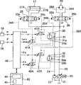
Fig. 5 is the gyroscopic drive system of embodiment 1 and the block diagram of wobble drive system.
Fig. 6 is the output characteristics figure of the controller of embodiment 1.
Fig. 7 is the gyroscopic drive system of embodiments of the invention 2 and the block diagram of wobble drive system.
Fig. 8 is the output characteristics figure of the controller of embodiment 2.
Fig. 9 is the job description figure of the alternate manner of embodiment 2.
Figure 10 is the output characteristics figure of controller of the alternate manner of embodiment 2.
Figure 11 is the job description figure of the another way of embodiment 2.
The specific embodiment
Below, with reference to accompanying drawing embodiment is elaborated.And, all around and all directions up and down, unless otherwise specified, all mean be install oscillating control device of the present invention the swing type hydraulic excavator all around and up and down.
Adopt Fig. 1~Fig. 6 that embodiments of the invention are described.As Fig. 1 and shown in Figure 2, hydraulic crawler excavator 1 is provided with: the working rig 4 of the leading section that have the lower running body 2 of left and right sides crawler unit, the top revolving body 3 that can be installed with freely to rotate on the top of lower running body 2, is installed in top revolving body 3.Carrying driver's cabin 5 in the anterior left side of top revolving body 3 and be equipped with counterweight 6 in the rearward end of top revolving body 3.As the rear portion of the top revolving body 3 of the hydraulic crawler excavator 1 of the little rotary type in rear, be can be in maximum back-end radius the drum of rotating basic semicircle.
Working rig 4, have base end part and can free rough ground be installed in the rocking arm 12 of boom 11 on the rocking bracket 10, leading section that base end part is installed in boom 11 free to rotately, the scraper bowl 13 of the instrument of using as operation, its base end part is installed in the leading section of rocking arm 12 free to rotately.Working rig 4 also have the boom oil cylinder 14 that is installed between rocking bracket 10 and the boom 11, be installed in the rocking arm oil cylinder 15 between boom 11 and the rocking arm 12 and be installed in rocking arm 12 and scraper bowl 13 between bucket cylinder 16, by the telescopic drive of these oil cylinders 14,15,16, drive working rig 4.
Support to rocking bracket 10 as the boom 11 of the base end part of working rig 4, as shown in Figure 3, can be on the Support bracket 8 that is installed in the leading section that is arranged at top revolving body 3 by the pin 9 of above-below direction with freely swinging on the left and right directions.And, by the telescopic drive of the oscillating oil cylinder 17 of installation between leading section from the pull lever 10a that is provided with to the right side of rocking bracket 10 (upside of Fig. 3) that give prominence to and top revolving body 3, drive working rig 4 with rocking bracket 10 swings.
Leading section at top revolving body 3, be installed with can wobble detection carriage 10 waving angle, be the pendulum angle sensor 18 of pendulum angle α of the left and right directions of working rig 4, the angle of revolution sensor 19 (with reference to Fig. 1) of the angle of revolution θ that detects top revolving body 3 is installed in the bottom of top revolving body 3.Each angular transducer 18,19 is such as with the potentiometer position being the main body formation.In addition, in the present embodiment, angle of revolution θ is a positive-angle with turn clockwise (right rotation) from the front, the place ahead of lower running body 2, and pendulum angle α is a positive-angle with the inhour rotation (left side swing) from the front, the place ahead of top revolving body 3.
As mentioned above, hydraulic crawler excavator 1 is the swing type hydraulic excavator with the arm-type working rig 4 of swing lifting.Therefore, such as shown in Figure 4, by only with pendulum angle α 0 direction wobble drive working rig 4 and roughly equally rotate with the angle of revolution θ 0 of the right opposite and to drive top revolving body 3 left with angle [alpha] 0 with swaying direction, the front position of working rig 4 can be offset to the right mobilely from the wide center of car body, make to become easy along the ditching operation on the wall limit on car body right side.
As shown in Figure 5, motor 20 as the oil pump 21 of the variable capacity type of drive source rotation and the discharge side that produces the oil pump 22 of controlled pressure, is distinguished connecting line 23,24.Pipeline 23 and swinging operation valve 25, revolution operation valve 26 and not shown other operation valves (such as, boom operation valve, rocking arm operation valve etc.) connect, the pressure oil that oil pump 21 is discharged offers these operation valves.Swinging operation valve 25 connects oscillating oil cylinder 17 by pipeline 27A, the 27B of primary side.Revolution operation valve 26 connects rotary motor 29 by pipeline 28A, the 28B of primary side.
In control piper 34A, 34B, 35A, 35B, command signal i α A, i α B, i θ A, i θ B proportion magnetic valve 41A, 41B, 42A, the 42B to drive of origin self-controller 40 is installed respectively.In control 40, connect pendulum angle sensing 18 and angle of revolution sensor 19, controller 40 is according to from the swing α angle signal of pendulum angle sensor 18 and from the angle of revolution signal θ of angle of revolution sensor 19, for carry out computing and output to the command signal i of proportion magnetic valve 41A, 41B, 42A, 42B α A, i α B, i θ A, i θ B.
On controller 40, connect monitor plate 43, and carry out the reception and the transmission of various signals between the control 40.Monitor plate 43 has display 44 and loader 45.On display 44, demonstration is the side-play amount of direction to the left and right from the wide center of car body of the cardinal extremity (oscillation center) of the working rig 4 of calculating based on angle of revolution θ, with the various quantity of states of poor (being the driving plane angulation of car body fore-and-aft direction and working rig 4) of angle of revolution θ and the angle of oscillation α vehicle that is initial state and setting value etc.On loader 45, be provided with multiple switch, can carry out the switching of input, change and the work pattern (manual mode, set stop mode, Automatic Control pattern etc.) of the setting values such as switching, stop position of the displaying contents of display 44.
As example, present angle of revolution θ n and pendulum angle α n are stored as the setting value (θ 0, α 0) of stop position by loader 45 setting value input contents.Promptly, operation swinging operation pull lever 32 and swinging operation pedal 30, set desirable side-play amount with manual mode in advance, to top revolving body 3 and working rig 4 location, by be arranged on the configuration switch (not shown) of the regulation on the loader 45 in this position operation, present angle of revolution θ n and pendulum angle α n are also stored as setting value (θ 0, α 0).Below, for with angle of revolution θ 0 when excavating and the pendulum angle α 0 of being offset shown in Figure 4 as the storage of stop position setting value, and the output characteristics that work pattern is switched to the controller 40 under the situation of ' setting value stop mode ' describes with reference to Fig. 6.
Excavate moving of position and the working rig 4 between the casting position of dump truck, drive by common revolution and carry out.When working rig being returned the excavation position, the operator of excavator drives top revolving body 3 by the relief portion 33b of revolution operation pull lever 32 operation control valves 33 to right-hand rotation.Shown in Fig. 6 (a), being position θ 1 to the set positions before the predetermined angular d θ from setting angle of revolution θ 0, so to the command signal i θ B of the proportion magnetic valve 42B of the controlled pressure that can control right-hand rotation, if angle of revolution θ is more approaching than position θ 1, it then is 100% output signal (the opening amount of proportion magnetic valve 42B is a standard-sized sheet), set angle of revolution θ 0 along with approaching from position θ 1, corresponding angle of revolution θ, lowering gradually from 100% is m%, in setting angle of revolution θ, as the characteristic that becomes 0% from m%.Here, m%, even be scram revolution operation valve 26, swing is stopped suddenly, also can not produce the slower swing speed ω θ 0 of sense of discomfort degree to the operator, such as the output that is about 10%, predetermined angular d θ is even be set to the enough angular ranges when maximum, till decelerating to swing speed ω θ 0 as speed of gyration ω θ.For left side swing, be set to the command signal i θ A of proportion magnetic valve 42A output and have same characteristic (not shown).
Moving of working rig 4 can have wobble drive to carry out.Therefore, shown in Fig. 6 (b), beginning to be made as position alpha 1 to predetermined angular d α position nearby from setting pendulum angle α 0, with the controlled pressure of controllable right swing to the command signal i α B of proportion magnetic valve 41B, if pendulum angle α is nearer than position alpha 1, it then is 100% output signal (the opening amount of proportion magnetic valve 41B is a standard-sized sheet), and along with approach setting pendulum angle α 0 from position alpha 1, it is n% that the corresponding pendulum angle α of institute lowers gradually from 100%, in setting pendulum angle α, as the characteristic that becomes 0% from n%.Here, for n%, even scram swinging operation valve 25, swing is stopped suddenly, also can not produce the slower swing speed ω α 0 of sense of discomfort degree to the operator, such as the output that is about 5%, predetermined angular d α, even be set to when swing speed ω α is maximum, decelerate to the enough angular ranges till the swing speed ω α 0.For left side swing, will be set at same characteristic (not shown) to the command signal i θ A of proportion magnetic valve 41A output.
Command signal i α A, the i α B, i θ A, the i θ B that send owing to the controller 40 from ' setting value stop mode ' are above-mentioned output characteristics, so reduce gradually from predetermined angular d θ controlled pressure nearby, controlled pressure cut off at angle of revolution θ 0 as the angle of revolution θ 0 of the setting value of stop position.Thus, even the operator continues operation revolution pull lever 32, revolution drives also can slow down at the angle of revolution θ 0 as setting value and stops.Equally, reduce gradually, controlled pressure is cut off at pendulum angle α 0 from predetermined angular d α controlled pressure nearby as the pendulum angle α 0 of the setting value of stop position.Thus, even the operator continues operation swinging operation pedal 30, wobble drive also can be slowed down at the pendulum angle α 0 as setting value and be stopped.
The effect of present embodiment then, is described.The offset orientation operation of manual mode becomes easy.Promptly, present ' side-play amount ' of cardinal extremity of expression working rig 4 on display 44, thus, the rotation amount of movement to the excavation position of corresponding side-play amount is not obtained by range estimation, but can confirm by numeric representation, make the rotation of manual mode move and correctly carry out and operation easily.And, on display 44, show the poor of angle of revolution θ and pendulum angle α, make this difference become zero by rotation or swing, can the driving plane of working rig 4 is consistent with the car body direction of travel.That is, confirm displaying contents, and the engineering from posture to the ditch skew that excavate that obtains smart height becomes easy.
And, by ' side-play amount ' difference consistent with desirable amount, that make demonstration that makes demonstration is zero, can with by ' excavating posture ' to the ditch skew with the scraper bowl 13 of working rig 4 with excavate position consistency (correctly with the driving plane of working rig 4 with excavate plan on the line consistent).Thus, making the high ditch of required precision excavate also is easy to carry out.And needn't adopt special device for the formation of control system, as long as adopt proportion magnetic valve 41A, 41B, 42A, 42B and potentiometer (pendulum angle sensor 18, angle of revolution sensor 19) to constitute, become low-cost device with versatility.
And, by work pattern being switched to ' setting value stop mode ', even the operator continues operation, but, revolution stops by separately setting value (θ 0, α 0) because driving with wobble drive, so get rid of after the native sand, working rig 4 and each identical operation driving plane unanimity can be made that the dredge operation in same place becomes easy.Certainly, the casting position can be set, and at this moment, the casting operation in same place also becomes easy.Also can set together and excavate position and casting position.
Store as the setting value of stop position by angle of revolution θ and pendulum angle α desirable ' excavating posture ' to the ditch skew, can stop with same ' excavating posture ' to the ditch skew at every turn, make that the ditch digging operation consistent with the car body direction of travel becomes easily, increased substantially operating efficiency.And then, according to the control that stops of ' setting value stop mode ', be stopping after the predetermined angular deceleration nearby, so the impact when stopping is little, can not cause sense of discomfort, can not produce native sand and drop the operator, operability is fine.
Next adopts Fig. 7 and Fig. 8 that embodiments of the invention 2 are described.To the same symbol of formation employing similarly to Example 1, and omit its explanation.In embodiment 1, it is the example that adopts by the drive system of the oil pressure control type of the control valve 33 of the control valve 31 of swinging operation pedal 30 operations and 32 operations of revolution operation pull lever, and in embodiment 2, be to adopt the drive system applications of automatically controlled standard of detector of operational ton of the operational ton of electricity consumption wobble detection operating pedal 30 respectively and revolution operation pull lever 32 in example of the present invention.
As shown in Figure 7, controller 50, according to from the amount of pedal operation signal δ α of the pedal operation quantity sensor 53 of the operational ton of wobble detection operating pedal 30 and from the pendulum angle signal alpha of pendulum angle sensor 18, command signal i α A, the i α B of subtend set proportion magnetic valve 51A, 51B output on control piper 55A, the 55B of the operating portion 25a, the 25b that connect swinging operation valve 25 respectively and oil pump 22, carry out computing and output.And, controller 50, according to from the amount of pedal operation signal δ θ of the pull lever operational ton sensor 54 of the operational ton that detects revolution operation pull lever 32 and the angle of revolution signal θ of angle of revolution sensor 19, command signal i θ A, the i θ B of proportion magnetic valve 52A, the 52B output that subtend is provided with on control piper 56A, the 56B of the operating portion 26a, the 26b that connect revolution operation valve 26 respectively and oil pump 22 carry out computing and output.
When common operation, controller 50, output and the proportional substantially command signal i α of swing amount of pedal operation δ α A, i α B and with the proportional substantially command signal i θ of revolution action bars operational ton δ θ A, i θ B.On the other hand, command signal i α A, i α B, i θ A, i θ B from the controller 50 of ' setting value stop mode ' is exported for stop position setting value (θ 0, α 0), are output characteristics as shown in Figure 8.Promptly, command signal i α A, i α B, be with the proportional substantially swing instruction of swing amount of pedal operation δ α a reference value s α A, s α B on, multiply by the value (with reference to Fig. 8 (a)) that has with at the gain characteristic k of output characteristics identical characteristics illustrated in fig. 6 α A, k α B.Command signal i θ A, i θ B, be with the proportional substantially revolution instruction of revolution action bars operational ton δ θ a reference value s θ A, s θ B on, multiply by the value (with reference to Fig. 8 (b)) that has with at the gain characteristic k of output characteristics identical characteristics illustrated in fig. 6 θ A, k θ B.
Thus, in the drive system of the automatically controlled standard of embodiment 2, also can obtain same action effect under the situation with the drive system of the oil pressure control type of embodiment 1, and, in the drive system of the automatically controlled standard of standard, owing to append pendulum angle sensor 18 and angle of revolution sensor 19, can constitute the expression that can control side-play amount, the oscillating control device that stops of setting value, obtain control device very cheaply.
In addition, the invention is not restricted to the embodiments described, can increase some change and correction within the scope of the invention.Such as, as near the output characteristics the setting value, be to be the example explanation with the characteristic that linearity reduces, even but nonlinear, and if have to setting value characteristic decrescence, also can be the characteristic of curve, broken line shape.Thus, the impact the during speed change that can make when slowing down beginning etc. becomes very little, can improve operator's operating environment.
The setting value of stop position as ' setting value stop mode ' storage, be so that present angle of revolution θ n and pendulum angle α n are saved as the explanation that example is carried out as setting value (θ 0, α 0), also angle of revolution θ that can wish from loader 45 inputs and storage and pendulum angle α (θ under desired situation from posture to the ditch skew that excavate=α).In addition, the also side-play amount that can wish from loader 45 input, angle of revolution θ and the pendulum angle α that transfer pair should side-play amount also stores.At this moment, tens word button and data storage switch can be set, in ' data setting pattern ', as long as the data of storing and setting value (θ 0, α 0) as the switch of loader 45.Perhaps, also can be after the data that stored the side-play amount of wishing, according to the distance of the centre of gyration, obtain storage after angle of revolution θ 0 that should side-play amount and the pendulum angle α 0.
As the setting value that stores with ' setting value stop mode ', as shown in Figure 9, store two deviation post h1, h2, when the excavation position is returned in casting later on, can alternately stop at position h1, h2.Thus, for the ditch wideer, can carry out high-precision excavation at an easy rate than the width of scraper bowl 13.
In embodiment 2, for example, generate automatically by controller 50 and command signal i α A as shown in figure 10, i α B, i θ A, i θ B that output moves to setting value (θ 0, α 0) and stops the present arbitrarily rotary position θ n from the casting position etc. and swing position α n with ' Automatic Control pattern '.At this moment, as long as move with the speed that is predetermined.Like this, the operator need not operate swinging operation pedal 30 and revolution operation pull lever 32, only by then working rig 4 being moved to desirable excavation position from the optional position to pressing of (can turning round operation pull lever 32 or swinging operation pedal 30) such as firing switcies set on the loader 45 as starting signal, make processing ease, can improve operation.
And then, in embodiment 2, drive and the operation of the facility (revolution operation pull lever 32 or swinging operation pedal 30) of the driving operation of any one party of wobble drive by rotation, driving with the either party is ' master ', the opposing party's driving is ' assisting ', often keep that ' angle of revolution θ=pendulum angle α ' can add as movable operation machine 4 and drives ' excavating the posture mode to ditch skew ' function of control.In addition, at this moment, from ' state of angle of revolution θ ≠ pendulum angle α ', with this function mobile operating machine 4, as shown in figure 11, after the either party by rotation driving and wobble drive moved to ' θ=α ', the control of keeping ' θ=α ' got final product.That is, working rig 4 to right-hand when mobile, like that, such as the state from a P1 such ' θ>α ', can be at first moved to by left wobble drive and keeps ' θ=α ' after ' θ=α ' and move shown in Figure 11 (a).From the state of a P2 such ' θ<α ', can be at first drive, move to ' θ=α ' by right-hand rotation after, keep ' θ=α ' and move.And, when working rig 4 is moved left to the right, shown in Figure 11 (b) like that, from the state of a P3 such ' θ>α ', can be at first by left side revolution drive move to ' θ=α ' after, keep ' θ=α ' and move.From the state of a P4 such ' θ<α ', can be at first move to ' θ=α ' by right wobble drive after, keep ' θ=α ' and move.
Thus, even the driving plane of revolution, working rig 4 also can be always and the direction of car body walking be consistent (can always keep ' excavating posture to the ditch skew '), therefore working rig 4 can not have big waving to the car body left and right directions, needn't worry working rig 4 and wall or the collision of other traffick.By ' side-play amount ' of this ' to ditch skew excavation posture pattern ' expression is consistent with desirable amount, can make the scraper bowl 13 and excavation position consistency of working rig 4 easily, improve operating efficiency.
Also can replace the oil pump 22 that the generation controlled pressure is set, and reducing valve is set on pipeline 23, come controlled pressure.Also can on controller 40,50, connect adjuster, adjust the value of the angle d θ, d α, m%, n% etc. of output characteristics by operator's custom with switch, potentiometer.And angular transducer the 18, the 19th is counted the explanation that example is carried out with current potential, but is not limited to potentiometer, also can use encoder.Oscillatory gearing mechanism also is not limited to oil cylinder 17, also can be hydraulic motor, electro-motor, electronic cylinder etc.Equally, device for revolving and driving also is not limited to hydraulic motor 29, also can be electro-motor.When using electro-motor, electronic cylinder, can be by department's clothes amplifier control rate on controller.
As described above, according to the present invention, owing on display, show the side-play amount of the cardinal extremity of working rig, by confirming displaying contents, can be correctly and easily carry out the revolution that ditch to corresponding side-play amount excavates the position and move.Owing on display, show the poor of angle of revolution and pendulum angle,, can enhance productivity so, can easily take be offset to ditch consistent of driving plane of working rig to excavate posture with the fore-and-aft direction of car body by confirming displaying contents.In addition, even the operator continues operation, revolution drives and wobble drive also can stop in the position of hope respectively, so that the excavation in same place becomes is easy.And then, set as above-mentioned stop position by excavating posture to the ditch skew, can easily working rig be moved to from the casting position to the ditch skew and excavate posture, increased substantially the efficient of the ditch digging operation of deviation post.And, if automatically carry out the operation of moving and stopping, making operation easier to above-mentioned stop position to press operation, operating efficiency improves more.
Claims (7)
1. the oscillating control device of a swing type hydraulic excavator, have: the top and the device for revolving and driving (29) rotatable, that driven by the operation of correspondence revolution operating means (32) that are installed in lower running body (2) are turned round the top revolving body (3) that drives, with base end part that can swing and the oscillatory gearing mechanism (17) that is driven by the operation of corresponding swinging operating device (30) are installed by the working rig of wobble drive (4) at the leading section of described top revolving body (3), it is characterized in that having:
Detect the angle of revolution detector (19) of the angle of revolution θ of described top revolving body (3);
Display (44);
According to angle of revolution signal θ from described angle of revolution detector (19) input, the present side-play amount to the car body left and right directions of the cardinal extremity of the described working rig of computing (4), and operation result is presented at controller (40) on the described display (44).
2. the oscillating control device of swing type hydraulic excavator as claimed in claim 1 is characterized in that: also have the pendulum angle detector (18) of the pendulum angle α that detects described working rig (4),
Described controller (40) computing angle of revolution θ and pendulum angle α's is poor, and operation result is presented on the described display (44).
3. the oscillating control device of a swing type hydraulic excavator, have: the top and the device for revolving and driving (29) rotatable, that driven by the operation of correspondence revolution operating means (32) that are installed in lower running body (2) are turned round the top revolving body (3) that drives, with base end part that can swing and the oscillatory gearing mechanism (17) that is driven by the operation of corresponding swinging operating device (30) are installed by the working rig of wobble drive (4) at the leading section of described top revolving body (3), it is characterized in that having:
Detect the angle of revolution detector (19) of the angle of revolution θ of described top revolving body (3);
Detect the pendulum angle detector (18) of the pendulum angle α of described working rig (4);
Set the stop position setting device (43) of the stop position of revolution driving and wobble drive;
According to from the angle of revolution signal θ of described angle of revolution detector (19) input, from the pendulum angle signal alpha of described pendulum angle detector (18) input and the setting value of setting by described stop position setting device (45) (θ 0, α 0), computing and output at the stop position of described setting value (θ 0, α 0), make the controller (40) of the command signal (i θ A, i θ B, i α A, i α B) that described device for revolving and driving (29) and described oscillatory gearing mechanism (17) stop respectively.
4. the oscillating control device of swing type hydraulic excavator as claimed in claim 3 is characterized in that: described stop position setting device (43) has the loader (45) of display (44) and the storage of indication stop position,
Described controller (40), according to angle of revolution signal θ from described angle of revolution detector (19) input, the present side-play amount to the car body left and right directions of the cardinal extremity of the described working rig of computing (4), and operation result is presented on the described display (44), described loader (45) will store described angle of revolution detector (19) when indicating and the detected value of described pendulum angle detector (18) stores as described setting value (θ 0, α 0) simultaneously.
5. the oscillating control device of a swing type hydraulic excavator, have: the top and the device for revolving and driving (29) rotatable, that driven by the operation of correspondence revolution operating means (32) that are installed in lower running body (2) are turned round the top revolving body (3) that drives, with base end part that can swing and the oscillatory gearing mechanism (17) that is driven by the operation of corresponding swinging operating device (30) are installed by the working rig of wobble drive (4) at the leading section of described top revolving body (3), it is characterized in that having:
Detect the angle of revolution detector (19) of the angle of revolution θ of described top revolving body (3);
Detect the pendulum angle detector (18) of the pendulum angle α of described working rig (4);
Detect the revolution operating means operational ton detector (54) of the operational ton δ θ of described revolution operating means (32);
Detect the swinging operating device operational ton detector (53) of the operational ton δ α of described swinging operating device (30);
According to from the operational ton signal δ θ of described revolution operating means operational ton detector (54) input and from any one operational ton signal of the operational ton signal δ α of described swinging operating device operational ton detector (53) input, from the angle of revolution signal θ of described angle of revolution detector (19) input and the pendulum angle signal alpha of importing from described pendulum angle detector (18), keep the driving plane of described working rig (4) and the consistent posture of fore-and-aft direction of described lower running body (2), and command signal (the i θ A that controls described device for revolving and driving (29) and described oscillatory gearing mechanism (17) is simultaneously also exported in computing, i θ B, i α A, i α B) controller (50).
6. as the oscillating control device of any described swing type hydraulic excavator in the claim 3~5, it is characterized in that:
Constitute described oscillatory gearing mechanism (17) by oil pressure actuation gear (17), and have:
Respective operations amount, control supply with described oil pressure actuation gear (17) pressure oil flow operation valve (25) and
The proportion magnetic valve of the controlled pressure of the described operation valve of controllable operation (25) (41A, 41B);
Described controller (40) by described command signal (i α A, i α B) is outputed to described proportion magnetic valve (41A, 41B), is controlled the flow of described operation valve (25).
7. as the oscillating control device of any described swing type hydraulic excavator in the claim 3~5, it is characterized in that:
Constitute described device for revolving and driving (29) by oil pressure actuation gear (29), and have:
Respective operations amount, control supply with described oil pressure actuation gear (29) pressure oil flow operation valve (26) and
The proportion magnetic valve of the controlled pressure of the described operation valve of controllable operation (26) (42A, 42B); Described controller (40) is controlled the flow of described operation valve (26) by described command signal (i θ A, i θ B) is outputed to described proportion magnetic valve (42A, 42B).
Applications Claiming Priority (2)
| Application Number | Priority Date | Filing Date | Title |
|---|---|---|---|
| JP2002280161A JP3929039B2 (en) | 2002-09-26 | 2002-09-26 | Swing control device for swing hydraulic excavator |
| JP2002280161 | 2002-09-26 |
Publications (2)
| Publication Number | Publication Date |
|---|---|
| CN1497105A CN1497105A (en) | 2004-05-19 |
| CN1237235C true CN1237235C (en) | 2006-01-18 |
Family
ID=32274928
Family Applications (1)
| Application Number | Title | Priority Date | Filing Date |
|---|---|---|---|
| CNB031597556A Expired - Fee Related CN1237235C (en) | 2002-09-26 | 2003-09-24 | Oscillation control device of oscillation type hydraulic digging machine |
Country Status (3)
| Country | Link |
|---|---|
| JP (1) | JP3929039B2 (en) |
| KR (1) | KR20040027349A (en) |
| CN (1) | CN1237235C (en) |
Families Citing this family (18)
| Publication number | Priority date | Publication date | Assignee | Title |
|---|---|---|---|---|
| JP4712625B2 (en) * | 2006-07-04 | 2011-06-29 | 日立建機株式会社 | Swing control device for swing type hydraulic excavator |
| KR101104027B1 (en) | 2006-11-22 | 2012-01-06 | 현대중공업 주식회사 | The Swing Control Method of Boom_swing Excavator by The Proximity Sensors |
| CN102051895B (en) * | 2009-11-05 | 2012-08-08 | 北汽福田汽车股份有限公司 | Travelling control device and method for excavator |
| CN102060243B (en) * | 2011-01-20 | 2013-06-19 | 上海三一科技有限公司 | Wireless remotely-controlled deviation-checking device for crawler-type counterweight trolley and control method thereof |
| CN102556143B (en) * | 2012-02-08 | 2014-08-13 | 三一重工股份有限公司 | Method and device for controlling travelling direction of engineering mechanical equipment |
| JP5941014B2 (en) * | 2013-04-26 | 2016-06-29 | 日立建機株式会社 | Double arm working machine |
| CN103306329B (en) * | 2013-05-28 | 2016-04-13 | 上海三一重机有限公司 | A kind of hydraulic shear micro-control control system based on excavator and method and excavator |
| JP6190297B2 (en) * | 2014-03-17 | 2017-08-30 | 川崎重工業株式会社 | Operating device |
| US10344454B2 (en) | 2014-06-06 | 2019-07-09 | Cnh Industrial America Llc | System for coordinating the direction of travel of a hydraulic machine with the operator's position |
| JP6345080B2 (en) * | 2014-10-30 | 2018-06-20 | 日立建機株式会社 | Work machine turning support device |
| JP6716358B2 (en) * | 2016-06-21 | 2020-07-01 | 株式会社小松製作所 | Work vehicle, work management system, and work vehicle control method |
| CN110325687B (en) * | 2017-02-24 | 2022-06-14 | 住友重机械工业株式会社 | Shovel, shovel control method, and portable information terminal |
| JP6962743B2 (en) * | 2017-08-23 | 2021-11-05 | 大成建設株式会社 | Turn control system for work vehicles |
| JP6962841B2 (en) * | 2018-03-22 | 2021-11-05 | ヤンマーパワーテクノロジー株式会社 | Turning work vehicle display system |
| CN109407563A (en) * | 2018-12-26 | 2019-03-01 | 北京百度网讯科技有限公司 | The control system and its control method of unmanned engineering machinery |
| JP7423399B2 (en) * | 2020-04-17 | 2024-01-31 | 株式会社小松製作所 | Work system and control method |
| JP2023171009A (en) | 2022-05-20 | 2023-12-01 | 株式会社小松製作所 | Work machine and swing angle information detection device |
| CN114960800B (en) * | 2022-06-21 | 2024-03-29 | 徐州徐工挖掘机械有限公司 | Deflection adjusting system and method |
-
2002
- 2002-09-26 JP JP2002280161A patent/JP3929039B2/en not_active Expired - Fee Related
-
2003
- 2003-09-18 KR KR1020030064889A patent/KR20040027349A/en not_active Application Discontinuation
- 2003-09-24 CN CNB031597556A patent/CN1237235C/en not_active Expired - Fee Related
Also Published As
| Publication number | Publication date |
|---|---|
| CN1497105A (en) | 2004-05-19 |
| JP2004116108A (en) | 2004-04-15 |
| KR20040027349A (en) | 2004-04-01 |
| JP3929039B2 (en) | 2007-06-13 |
Similar Documents
| Publication | Publication Date | Title |
|---|---|---|
| CN1237235C (en) | Oscillation control device of oscillation type hydraulic digging machine | |
| CN1234943C (en) | Oscillating controller for oscillating hydraulic dredger | |
| JP7171798B2 (en) | Excavator, system for excavator, and method for controlling excavator | |
| KR102126772B1 (en) | Working machine | |
| CN1863971A (en) | Multi-function work machine | |
| WO2015186201A1 (en) | Excavating machinery control system and excavating machinery | |
| CN108779614A (en) | Work machine | |
| CN201003175Y (en) | Small angle slewing equipment for small-sized digger | |
| JP6585532B2 (en) | Small excavator | |
| WO2019012701A1 (en) | Work machine and control method of work machine | |
| CN1210570A (en) | Controller of construction machine | |
| WO2018174084A1 (en) | Construction machinery | |
| CN1306122C (en) | Controller for oscillating hydraulic bucket shovelling machine | |
| CN1179805A (en) | Link device for hydraulic shovel | |
| CN116635593A (en) | Engineering machinery | |
| CN115210430A (en) | Hydraulic excavator | |
| WO2023276421A1 (en) | Construction machine | |
| WO2022215414A1 (en) | Excavation system | |
| WO2023149104A1 (en) | Work machine and method for controlling work machine | |
| KR0112411Y1 (en) | Counterweight control device of the dredgers | |
| CN118119749A (en) | Engineering machine and control method for engineering machine | |
| JPH06264464A (en) | Power shovel | |
| JP2024005170A (en) | Construction machine | |
| KR950002127B1 (en) | Control method of leveling work for excavator | |
| JPH0549772B2 (en) |
Legal Events
| Date | Code | Title | Description |
|---|---|---|---|
| C06 | Publication | ||
| PB01 | Publication | ||
| C10 | Entry into substantive examination | ||
| SE01 | Entry into force of request for substantive examination | ||
| C14 | Grant of patent or utility model | ||
| GR01 | Patent grant | ||
| C19 | Lapse of patent right due to non-payment of the annual fee | ||
| CF01 | Termination of patent right due to non-payment of annual fee |