CN1204448C - Improved back transmission electrophoresis display - Google Patents
Improved back transmission electrophoresis display Download PDFInfo
- Publication number
- CN1204448C CN1204448C CNB011450533A CN01145053A CN1204448C CN 1204448 C CN1204448 C CN 1204448C CN B011450533 A CNB011450533 A CN B011450533A CN 01145053 A CN01145053 A CN 01145053A CN 1204448 C CN1204448 C CN 1204448C
- Authority
- CN
- China
- Prior art keywords
- epd
- display device
- electrophoretic display
- box
- color
- Prior art date
- Legal status (The legal status is an assumption and is not a legal conclusion. Google has not performed a legal analysis and makes no representation as to the accuracy of the status listed.)
- Expired - Fee Related
Links
Images


Classifications
-
- G—PHYSICS
- G02—OPTICS
- G02F—OPTICAL DEVICES OR ARRANGEMENTS FOR THE CONTROL OF LIGHT BY MODIFICATION OF THE OPTICAL PROPERTIES OF THE MEDIA OF THE ELEMENTS INVOLVED THEREIN; NON-LINEAR OPTICS; FREQUENCY-CHANGING OF LIGHT; OPTICAL LOGIC ELEMENTS; OPTICAL ANALOGUE/DIGITAL CONVERTERS
- G02F1/00—Devices or arrangements for the control of the intensity, colour, phase, polarisation or direction of light arriving from an independent light source, e.g. switching, gating or modulating; Non-linear optics
- G02F1/01—Devices or arrangements for the control of the intensity, colour, phase, polarisation or direction of light arriving from an independent light source, e.g. switching, gating or modulating; Non-linear optics for the control of the intensity, phase, polarisation or colour
- G02F1/165—Devices or arrangements for the control of the intensity, colour, phase, polarisation or direction of light arriving from an independent light source, e.g. switching, gating or modulating; Non-linear optics for the control of the intensity, phase, polarisation or colour based on translational movement of particles in a fluid under the influence of an applied field
- G02F1/166—Devices or arrangements for the control of the intensity, colour, phase, polarisation or direction of light arriving from an independent light source, e.g. switching, gating or modulating; Non-linear optics for the control of the intensity, phase, polarisation or colour based on translational movement of particles in a fluid under the influence of an applied field characterised by the electro-optical or magneto-optical effect
- G02F1/167—Devices or arrangements for the control of the intensity, colour, phase, polarisation or direction of light arriving from an independent light source, e.g. switching, gating or modulating; Non-linear optics for the control of the intensity, phase, polarisation or colour based on translational movement of particles in a fluid under the influence of an applied field characterised by the electro-optical or magneto-optical effect by electrophoresis
-
- G—PHYSICS
- G02—OPTICS
- G02F—OPTICAL DEVICES OR ARRANGEMENTS FOR THE CONTROL OF LIGHT BY MODIFICATION OF THE OPTICAL PROPERTIES OF THE MEDIA OF THE ELEMENTS INVOLVED THEREIN; NON-LINEAR OPTICS; FREQUENCY-CHANGING OF LIGHT; OPTICAL LOGIC ELEMENTS; OPTICAL ANALOGUE/DIGITAL CONVERTERS
- G02F1/00—Devices or arrangements for the control of the intensity, colour, phase, polarisation or direction of light arriving from an independent light source, e.g. switching, gating or modulating; Non-linear optics
- G02F1/01—Devices or arrangements for the control of the intensity, colour, phase, polarisation or direction of light arriving from an independent light source, e.g. switching, gating or modulating; Non-linear optics for the control of the intensity, phase, polarisation or colour
- G02F1/165—Devices or arrangements for the control of the intensity, colour, phase, polarisation or direction of light arriving from an independent light source, e.g. switching, gating or modulating; Non-linear optics for the control of the intensity, phase, polarisation or colour based on translational movement of particles in a fluid under the influence of an applied field
- G02F1/1675—Constructional details
- G02F1/1679—Gaskets; Spacers; Sealing of cells; Filling or closing of cells
-
- G—PHYSICS
- G02—OPTICS
- G02F—OPTICAL DEVICES OR ARRANGEMENTS FOR THE CONTROL OF LIGHT BY MODIFICATION OF THE OPTICAL PROPERTIES OF THE MEDIA OF THE ELEMENTS INVOLVED THEREIN; NON-LINEAR OPTICS; FREQUENCY-CHANGING OF LIGHT; OPTICAL LOGIC ELEMENTS; OPTICAL ANALOGUE/DIGITAL CONVERTERS
- G02F1/00—Devices or arrangements for the control of the intensity, colour, phase, polarisation or direction of light arriving from an independent light source, e.g. switching, gating or modulating; Non-linear optics
- G02F1/01—Devices or arrangements for the control of the intensity, colour, phase, polarisation or direction of light arriving from an independent light source, e.g. switching, gating or modulating; Non-linear optics for the control of the intensity, phase, polarisation or colour
- G02F1/13—Devices or arrangements for the control of the intensity, colour, phase, polarisation or direction of light arriving from an independent light source, e.g. switching, gating or modulating; Non-linear optics for the control of the intensity, phase, polarisation or colour based on liquid crystals, e.g. single liquid crystal display cells
- G02F1/133—Constructional arrangements; Operation of liquid crystal cells; Circuit arrangements
- G02F1/1333—Constructional arrangements; Manufacturing methods
- G02F1/1343—Electrodes
- G02F1/134309—Electrodes characterised by their geometrical arrangement
- G02F1/134363—Electrodes characterised by their geometrical arrangement for applying an electric field parallel to the substrate, i.e. in-plane switching [IPS]
-
- G—PHYSICS
- G02—OPTICS
- G02F—OPTICAL DEVICES OR ARRANGEMENTS FOR THE CONTROL OF LIGHT BY MODIFICATION OF THE OPTICAL PROPERTIES OF THE MEDIA OF THE ELEMENTS INVOLVED THEREIN; NON-LINEAR OPTICS; FREQUENCY-CHANGING OF LIGHT; OPTICAL LOGIC ELEMENTS; OPTICAL ANALOGUE/DIGITAL CONVERTERS
- G02F1/00—Devices or arrangements for the control of the intensity, colour, phase, polarisation or direction of light arriving from an independent light source, e.g. switching, gating or modulating; Non-linear optics
- G02F1/01—Devices or arrangements for the control of the intensity, colour, phase, polarisation or direction of light arriving from an independent light source, e.g. switching, gating or modulating; Non-linear optics for the control of the intensity, phase, polarisation or colour
- G02F1/165—Devices or arrangements for the control of the intensity, colour, phase, polarisation or direction of light arriving from an independent light source, e.g. switching, gating or modulating; Non-linear optics for the control of the intensity, phase, polarisation or colour based on translational movement of particles in a fluid under the influence of an applied field
- G02F1/1675—Constructional details
- G02F1/1679—Gaskets; Spacers; Sealing of cells; Filling or closing of cells
- G02F1/1681—Gaskets; Spacers; Sealing of cells; Filling or closing of cells having two or more microcells partitioned by walls, e.g. of microcup type
-
- G—PHYSICS
- G02—OPTICS
- G02F—OPTICAL DEVICES OR ARRANGEMENTS FOR THE CONTROL OF LIGHT BY MODIFICATION OF THE OPTICAL PROPERTIES OF THE MEDIA OF THE ELEMENTS INVOLVED THEREIN; NON-LINEAR OPTICS; FREQUENCY-CHANGING OF LIGHT; OPTICAL LOGIC ELEMENTS; OPTICAL ANALOGUE/DIGITAL CONVERTERS
- G02F2201/00—Constructional arrangements not provided for in groups G02F1/00 - G02F7/00
- G02F2201/12—Constructional arrangements not provided for in groups G02F1/00 - G02F7/00 electrode
-
- G—PHYSICS
- G02—OPTICS
- G02F—OPTICAL DEVICES OR ARRANGEMENTS FOR THE CONTROL OF LIGHT BY MODIFICATION OF THE OPTICAL PROPERTIES OF THE MEDIA OF THE ELEMENTS INVOLVED THEREIN; NON-LINEAR OPTICS; FREQUENCY-CHANGING OF LIGHT; OPTICAL LOGIC ELEMENTS; OPTICAL ANALOGUE/DIGITAL CONVERTERS
- G02F2203/00—Function characteristic
- G02F2203/09—Function characteristic transflective
Abstract
This invention relates to an electrophoretic display comprising isolated cells of well-defined shape, size and aspect ratio which cells are filled with charged pigment particles dispersed in a solvent, a backlight and optionally a background layer. The display may have the traditional up/down switching mode, an in-plane switching mode or a dual switching mode.
Description
The technical field of the invention
The present invention relates to a kind of back transmission electrophoresis display, this back transmission electrophoresis display comprise the shape that has clearly definition, size, with the barrier box of aspect ratio, described box is filled with the electrically charged particle that is scattered in the dielectric solvent, and this back transmission electrophoresis display has backlight.
The present invention can have traditional on/following switch mode, in-plane-switching mode or dual switch mode.
Background technology related to the present invention
Electrophoretic display device (EPD) (EPD) is based on a kind of non-emanative device that influence is suspended in the electrophoresis making of the electrically charged granules of pigments in the colored dielectric solvent.This electrophoretic display device (EPD) was proposed first in 1969.This class display generally includes relatively and puts, separated plate electrode.Usually, a battery lead plate at least wherein brings in to see it is transparent by observation.This kind passive electrophoretic display device (EPD) needs (to observe end) respectively at the top and the electrode drive of the row of bottom and row shows.By contrast, for the active type electrophoretic display device, EDD, need thin film transistor (TFT) array on the base plate and the common and patternless transparent conductor plate on the top view substrate.Electrophoretic fluid is made up of the electrically charged granules of pigments of painted dielectric solvent and dispersion, is sealed between two battery lead plates.
When between two electrodes, applying a voltage difference, because the pole plate of band opposite polarity attracts to make granules of pigments to this pole plate migration.Therefore, the color (by the decision of pole plate selective charge) that is presented on the transparent panel can be the color of solvent or the color of granules of pigments.Make particle move in the other direction the reversal of poles meeting of plate, thus also with color inversion.Different intermediate color (gray scale) is determined by the transition density of pigment of transparent polar plate, and can obtain by control voltage and duration of charging.
U.S. Patent No. 6,184,856 have disclosed a kind of transmission-type electrophoretic display device (EPD), the substrate that has wherein used backlight, chromatic filter and had two transparency electrodes.This electrophoresis cartridge plays the light valve effect.Gathering under the state (colleted state), this particle horizontal zone coverage that is used for box of arranging minimizes, and makes bias light pass through this box.In distributed state (distributed state), this particle horizontal zone that is used for pixel of arranging is covered, and bias light disperseed or absorbs.Yet employed bias light and filter can consume lot of energy in this device, for mancarried device, are unfavorable as PDA (personal digital assistant device) and e-book.
Record the electrophoretic display device (EPD) of different pixels or box structure in the prior art, for example, partition type electrophoretic display device (EPD) (M.A.Hopper and V.Novotny, IEEE Trans.Electr.Dev., Vol.ED 26, No.8, pp.1148-1152 (1979)) and the electrophoretic display device (EPD) (United States Patent (USP) the 5th, 961 of microcapsule method preparation, No. 804 and the 5th, 930, No. 026), and these prior aries have problem as described below separately.
In the electrophoretic display device (EPD) of partition type (partition-type), have several subregions between two electrodes, so that its space is divided into little unit, avoid undesirable particle migration (for example precipitation).Yet, can in following situation, encounter problems: form subregion, seal this fluid with this display of fluid filled, in display and keep the different colours suspension separated from one another.
The electrophoretic display device (EPD) of this microencapsulation has the microcapsules of primarily two-dimensional to be arranged, and wherein each microcapsules contains the electrophoresis component of being made up of dielectric medium fluid and electrically charged granules of pigments suspension (visually with the contrast of dielectric medium solvent).These microcapsules normally prepare in aqueous solution, in order to obtain useful contrast, its average particle size particle size relatively large (50-150 micron).The bulky grain size can cause relatively poor anti-scratch performance and have the slower response time for given voltage, this be since large capsule need be between between two opposite electrodes big gap.Moreover the hydrophilic outer shell of the microcapsules that prepare in aqueous solution is for high humility and temperature conditions sensitivity.If microcapsules are embedded in a large amount of polymer substrates to get rid of these shortcomings, then the use of this matrix can cause elongated and/or contrast of response time to reduce.For improving its switching rate, often need to use charge control agent in this class electrophoretic display device (EPD).Yet the Microencapsulation Method in the aqueous solution has limited the kind of spendable charge control agent.Other shortcomings about the microcapsules system comprise lower resolution and relatively poor color representation ability.
Recently, at the isonomic U.S. Patent application No.09/518 that submits on March 3rd, 2000,488, the U.S. Patent No. of submitting to January 11 calendar year 2001 09/759,212, the U.S. Patent No. of submitting on June 28th, 2,000 09/606,654, and in the U.S. Patent No. of submitting to February 15 calendar year 2001 09/784,972, disclosed the electrophoretic display technology of improvement, in the lump as a reference in this.The electrophoretic display device (EPD) of this improvement comprise the shape that has clearly definition, size, with the barrier box of aspect ratio, and this box is filled with the electrically charged granules of pigments that is dispersed in the solvent.This electrophoretic fluid is isolated and is sealed in each little shape cup.
In fact, this little shape cup structure can make the preparation form of electrophoretic display device (EPD) more flexible, realizes efficient roll-to-roll continuous manufacture process.This display can prepare on the continuous net-shaped conducting film as ITO/PET, for example, (1) radiation curable component is coated on the ITO/PET film, (2) prepare little shape cup structure with little mold pressing or photoetch method, (3) with electrophoresis liquid filling and this little shape cup of sealing, (4) being stacked in this with other conductive film layers will be on little shape cup of sealing, and (5) cut into required size or form with this display device and are used for assembling.
An advantage of this electrophoretic display device (EPD) design is that this little shape wall of cup is actually a kind of built-in sept that the top and bottom substrate is kept a fixed range.The mechanical property of little shape cup display and structural intergrity are better than the display of any prior art significantly, comprise the display that those use the spacer particles manufacturing.In addition, the display with the preparation of little shape cup all has desirable mechanical property, comprises when display bending, the reliable display performance that had when winding up or being subjected to the pressure form from for example touch screen application.The use of little shape cup technology has also been saved needs the edge sealed binder, and this edge sealed binder can limit and limit the display pannel size in advance, and has limited the display fluid that pre-determines in the zone.Display fluid in the conventional display device for preparing with edge seal bond agent method, when cutting in any manner or hole display device, this fluid can leak fully.The display device of this damaged will no longer have any function.Opposite, the demonstration fluid in the display device for preparing with the miniature cup technology is then sealed and be isolated from each box.Almost this miniature cup display can be cut into virtually any size, and not can because of show fluid in the zone of action loss and damage the risk of display device performance.In other words, this miniature cup structure can make the manufacturing disposal route form of display device flexible, and wherein this method can very big sheet specification be carried out display device and exported production continuously, and this sheet display device can cut into any required specification.When with the fluid filled electrophoresis cartridge of the different qualities of for example different colours, switching rate, the miniature cup of this isolation or the box structure particular importance that seems.If no miniature cup structure will prevent that fluid from mixing mutually or avoiding being subjected to the cross effect influence of operating period is very difficult in adjacent domain.
The invention summary
Watch reflective electrophoretic display device (EPD), need external light source.Because surface and light source administrative reason, for the application of observing in the dark, the back transmission electrophoresis display that is equipped with back light source system is better than having the reflective electrophoretic display device (EPD) of photosystem in eve usually.Yet the appearance of optical scatter in the electrophoretic display device (EPD) box greatly reduces the effectiveness of back light source system.For the electrophoretic display device (EPD) of traditional type, it all is difficult obtaining high-contrast in bright and dark surrounds.
The present invention relates to a kind of back transmission electrophoresis display that uses the miniature cup technology.This electrophoretic display device (EPD) comprises a plurality of by the box that comprises that the electrophoretic fluid that is scattered in the electrically charged granules of pigments in dielectric solvent or the solvent mixture is filled and divide the sealant that forms to seal by the low seal group of the more described electrophoretic fluid of proportion with miniature cup preparation, described box is separated by the limit wall of light-transmissive, and has backlight.With electrically charged particles filled this box that is scattered in the dielectric solvent.Wherein these a plurality of boxes comprise the box of different size and shape.
For the application of observing in dark surrounds, this miniature cup structure can make backlight arrive the observer through miniature wall of cup effectively.Therefore, for the user who watches back transmission electrophoresis display, even low intensive backlight also is enough.Can use the photoelectric cell sensor of adjusting backlight intensity, with the power consumption of further this type of electrophoretic display device (EPD) of reduction.
This electrophoretic display device (EPD) can have traditional on/following switch mode, in-plane-switching mode or dual switch mode.
Have traditional on/display of following switch mode or dual switch mode in, a top transparent electrode plate, bottom electrode plate are arranged, and a plurality of box that is closed in the isolation between two battery lead plates.In having the display of in-plane-switching mode, this box is sandwiched between top transparent insulator layer and the bottom electrode plate.
The box of this isolation is isolated by printing opacity box wall.This backlight is then below bottom electrode plate.This display also can have a background layer on back light source system, pass the light of this display with control.This background layer is preferably grey in use.Background layer under back light source system also can be used to improve contrast.
The top that also scatterer can be added to back transmission electrophoresis display is to strengthen visual effect.
Brief Description Of Drawings
Figure 1A is the side view of electrophoretic display device (EPD) of the present invention;
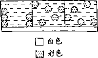
Figure 1B is the vertical view of electrophoretic display device (EPD) of the present invention;
Fig. 1 C is the side view that the present invention has the electrophoretic display device (EPD) of in-plane-switching mode;
Fig. 1 D is the side view that the present invention has the electrophoretic display device (EPD) of dual switch mode;
Fig. 2 represents to use the miniature cup preparation of the conducting film of ultraviolet light polymerization component coating to the ultraviolet radiation graph exposure;
Fig. 3 represents to make the process flow diagram of black/white electrophoretic display or other monochromatic electrophoretic display;
Fig. 4 a-4h is a process flow diagram of making full-color electrophoretic display device (EPD);
Fig. 5 A-5F diagram has the display of in-plane-switching mode; And
Fig. 6 A-6C illustrates the display with dual switch mode.
Detailed Description Of The Invention
Definition
Unless definition is arranged in patent specification in addition, otherwise at this all technology term all Use according to the common habitual definition of using and understanding of those skilled in the art.
Term " little shape cup " refers to utilize little mold pressing and graph exposure method, then carries out molten The cup-shaped recess of agent development made.
In this manual, term " box " refers to by the formed independence of a sealing miniature cup Unit. This box is filled out with the electrically charged granules of pigments that is dispersed in solvent or the solvent thing Fill.
When this miniature cup of explanation or box, term " has clearly defined " to refer to that this is miniature Cup or box have according to the predetermined clear and definite shape of the special parameter of this method, size, with in length and breadth Ratio.
Term " in length and breadth than " is the vocabulary known to general in the electrophoretic display device (EPD). At this specification In, the degree of depth that refers to this miniature cup is to width or the degree of depth ratio to diameter.
Term " isolation " refers to seal the electrophoresis cartridge of the indivedual sealing of layer, so that in a box Electrophoretic fluid can't be transferred in other boxes.
Detailed description of preferred embodiment
Shown in Figure 1A, electrophoretic display device (EPD) 100 of the present invention comprises a top clear 101, one bottom electrode plate 102, and is closed in the barrier box layer 103 between two battery lead plates.This top clear 101 is nesa coatings, for example is used for the ITO on the PET of traditional/following switch mode or dual switch mode, or is used for the transparent insulator layer of in-plane-switching mode.
Have clearly definition shape, size, with the box 103a of aspect ratio, 103b, and 103c, this box is filled with the electrically charged particle 104 that is scattered in the dielectric solvent 105.The box of this isolation is sealed with sealant 106.The top clear that generally includes adhesive phase is covered on the box of sealing.Backlight 107 places under the bottom electrode flaggy 102.This backlight can be on the edge of display, through scattering light pipe irradiation display pannel.This display optionally has a background layer 108 for 107 times at bottom electrode flaggy 102 or back light source system.
Figure 1B is the schematical top view of box.As shown in the figure, the edge of each box limits by separator vertical edges wall 109.This limit wall extends between top clear 101 and bottom electrode plate 102.It is perpendicular to illustrate this limit wall and top clear and bottom electrode plate among Figure 1A, it should be understood that this limit wall can tilt, with the preparation (the described knockout course of for example following chapters and sections I (a)) that helps box.In the present invention, this limit wall is made by light transmissive material.
Have traditional on/display of following switch mode in, top clear 101 is battery lead plate or film.
In having the display of in-plane-switching mode (Fig. 1 C), top clear 101 is insulator substrates, and bottom electrode plate has comprised electrode 110a, 110b in the face, and the bottom electrode 111 that is separated between the electrode and by groove 112 in two faces.Alternatively, this bottom layer can only have switching electrode and a bottom electrode that has groove betwixt in the face.
In having the display of dual switch mode (Fig. 1 D), top layer 101 has comprised transparent top electrode 116 (not shown).This bottom electrode plate on the left side has electrode 113a in the face, has a bottom electrode 114 and the interior electrode 113b of face on the right.Groove 115 with electrode in bottom electrode and the face separately.Alternatively, this bottom electrode plate can only have electrode and a bottom electrode (not shown) that has groove betwixt in the face.
I. the preparation of miniature cup
Miniature cup generally can be by the preparation of little mold pressing or photoetch method, as the U.S. Patent application No.09/518 that submits on March 3rd, 2000, and 488 and the U.S. Patent application No.09/784 that submits to February 15 calendar year 2001, described in 972.
I. (a) utilizes little die pressing to prepare the miniature cup array
The preparation of punch
Punch can for example after diamond cut technology or photoresist processing, be followed etching or plating with any suitable method preparation.The illustrative examples of punch as shown in Figure 2.Available any suitable method is made the master module of punch, for example electroplates.Adopt when electroplating, spraying one deck is generally the seed thin metal layer of 3000 dusts, for example inconel on a glass substrate.Then be coated with, and carry out radiant exposure, for example ultraviolet light (UV) with one deck photoresist layer.One mask is placed between this ultraviolet light and the photoresist layer.The exposure area hardening of this photo anti-corrosion agent material.Clean with appropriate solvent then and remove the zone of not exposing to the sun.The curing photoresist that keeps is carried out drying, and spraying plating one deck seed thin metal layer once more.Main mould is prepared the ready electrotyping process that carries out in back.The typical material that is used for electroforming is a nickel cobalt (alloy).In addition, this main mould can be made by nickel, as photo-optics Instrumentation Engineering teacher association journal volume 1663, " the continuous making of flash plating optical medium " (" Continuousmanufacturing of thin cover sheet optical media " among the pp.324 (1992), SPIE Proc.) illustrated in, adopt electroforming or electroless nickel deposition.The base plate of this mould is usually between about 50 to 400 microns.Also can use other little engineering to make this main mould, comprise that electron beam writes, dry-etching, chemical etching, laser writes or laser interference, " precision optics reproduction technology " (" Replicationtechniques for micro-optics " as the publication of photo-optics Instrumentation Engineering teacher association journal, SPIE Proc.) volume 3099, explanation among the pp.76-82 (1997).In addition, this mould can use plastics, pottery, metal, utilizes the light processing and fabricating.
Zhi Bei punch has about 3 to 500 microns projection usually like this, is preferably between about 5 to 100 microns, is preferably about 10 to 50 microns.Punch can be the form of band, roller, sheet.For continuous manufacturing, be preferably the mould of band shape or cylinder shape.Before coating UV-cured resin composition, can handle mould with release agent, to help knockout course.
The formation of miniature cup
Can make miniature cup with batch technology or continuous roller to roller technology.Disclose as the unsettled U.S. Patent application of submitting to February 15 calendar year 2001 09/784,972, this patented claim provides continuously, the manufacturing technology of low-cost, high production, with the compartment of using in manufacturing electrophoresis or the LCD (LCD).Before the coating UV-cured resin, mould can adopt release agent to help the demoulding to handle.For further improving release method, can be with on conducting film, being coated with a backing coating or adhesion-promoting layer in advance, to improve the bonding force between body and the miniature cup.
Can first degasification before the dispensing UV-cured resin, and can optionally comprise solvent.This solvent (if any) can easily evaporate.UV-cured resin can be dispensed on the punch in any suitable manner, for example is coated with, drips, topples over etc.Dispensing device can be movable type or fixed.For manufacturing have traditional on/display of following switch mode or dual switch mode, on conducting film, be coated with UV-cured resin.The conducting film embodiment that is fit to is included in the transparent conductor (ITO) on the plastic base, and these plastics are polyethylene terephthalate (polyethylene terephthalate), poly-naphthoic acid ethyl ester (polyethylenenaphthate), aromatic poly amide (polyaramid), polyimide, poly-cyclenes, polysulfones (polysulfone) and polycarbonate.Can exert pressure if necessary, guaranteeing that suitable joint is arranged between resin and the plastics, and the thickness of control miniature cup base plate.Can use laminated cylinder, vacuum model, pressue device or any other kindred organization to exert pressure.If punch is metal and opaque, then the plastic base typical case to go up for being used for for the actinic radiation of cured resin be transparent.On the contrary, punch can be transparent and plastic base is opaque for actinic radiation.For the model feature is transferred on the transfer sheet well, conducting film must have the good adhesion to UV-cured resin, and resin should have the good demolding performace for mold surface.
For manufacturing has the display of in-plane-switching mode, can in the mold pressing step, use transparent insulator substrate.The transparent insulator substrate that is fit to comprises polyethylene terephthalate (polyethylene terephthalate), poly-naphthoic acid ethyl ester (polyethylene napthate), aromatic poly amide (polyaramid), polyimide, poly-cyclenes, polysulfones (polysulfone) and polycarbonate.
The ultraviolet light polymerization component that is used to prepare miniature cup can comprise the acrylate or the methacrylate of multivalence, the vinyl of multivalence comprises the epoxide of vinyl benzene, vinyl silanes, vinyl ether, multivalence, the propylene of multivalence, and comprises the oligomer of crosslinking functionality or polymkeric substance or the like.Be preferably multi-functional acrylate and oligomer thereof.The composition of multi-functional epoxide and multi-functional acrylate is also very useful, can reach desired physical and mechanical properties.Usually also can add the crosslinkable oligomer of giving bending resistance, for example amido ethyl formate acrylate or polyester acrylate are to improve the bending resistance of mold pressing miniature cup.Composition can comprise polymkeric substance, oligomer, monomer and adjuvant, perhaps has only oligomer, monomer and adjuvant.The glass transition temperature of this class material (Tg) scope is usually from-70 ℃ to about 150 ℃ approximately, preferably from-20 ℃ to about 50 ℃ approximately.The process typical case of little mold pressing carries out being higher than under the glass transition temperature.Can use the indwelling substrate of the heating that the punch that heated or mould push down, to control the temperature and pressure of little mold pressing.This punch can break away from from the miniature cup that forms in this UV-cured resin during ultraviolet light photopolymerization or afterwards.
I. (b) prepares miniature cup with the light engraving method
Selectively, the available light engraving method prepares the miniature cup of display.Fig. 2 represents to prepare miniature cup with graph exposure method.
Shown in Fig. 2 A and 2B, available any known method is coated radiation curing material 21a on the conducting film 22 of one predetermined pattern, utilize 26 pairs of ultraviolet lights of a mask (maybe can select other forms of radiation, electron beam etc.) exposure, to form the wall 21b consistent with the mask projection figure, thereby preparation miniature cup array, wherein the conducting film 22 of this predetermined pattern is on plastic base 23.
In the photomask shown in Fig. 2 A 26, darkened boxes 24 representatives are to employed radiopaque zone, and radiation transparent region is then represented in the space 25 between this darkened boxes.This ultraviolet light passes through these open area 25 radiation on this radiation curing material 21a.
Shown in Fig. 2 B,, then remove unexposed zone (zone of opacity 24 by this mask 26 is hidden), and form this miniature cup 27 with appropriate solvent or developer through exposed areas 21b meeting hardening.This solvent or developer are selected from the preparation that is generally used for dissolving or disperseing radiation curing material, as butanone, toluene, acetone, isopropyl acetone etc.Though the conducting film 22 accurate alignments of 24 pairs of predetermined patterns of miniature cup pattern of photomask 26 in figure A2 are unessential for the application of general low resolution.
Selectively, can finish exposure under conducting film/substrate by photomask is placed.Under this situation, this conducting film/substrate must be transparent for the radiation wavelength that is used for exposing.
For manufacturing has the display of in-plane-switching mode, can use transparent insulator substrate to replace this conducting film.The transparent insulator substrate that is fit to comprises polyethylene terephthalate, poly-naphthoic acid ethyl ester, aromatic poly amide (polyaramid), polyimide, poly-cycloolefin, polysulfones, polycarbonate etc.
Usually, this miniature cup can be an arbitrary shape, and its size and shape can change.In a system, this miniature cup can have roughly the same size and dimension.Yet,, can make the different mixing miniature cup of shape and size in order to make the optical effect maximization.For example, can have different shapes or size with green miniature cup or blue miniature cup with the red miniature cup that disperses thing to fill.In addition, pixel can be made up of the miniature cup of the different colours of different numbers.For example, a pixel can be made up of a plurality of little green miniature cups, a plurality of big red miniature cup and a plurality of little blue miniature cup.Three kinds of colors needn't be of similar shape and number.
The opening of this miniature cup can be circle, square, rectangle, sexangle or any other shape.Interval region between the opening is preferably smaller, so that when keeping desirable engineering properties, obtains higher color saturation and contrast.Therefore, other shape of honeycomb aperture efficiency (for example circular) opening is better.
The size of each miniature cup can be about 10
2To about 1 * 10
6Between the square micron, preferred about 10
3To about 1 * 10
5Square micron.The degree of depth of this miniature cup is about 5 to about 200 microns, preferred about 10 to about 100 microns.This opening is about 0.05 to about 0.95, preferred about 0.4 to about 0.9 with the ratio of the total area.
The preparation of II suspension/dispersion thing
Be filled in suspension in the miniature cup and comprise that having electrically charged granules of pigments is scattered in wherein dielectric solvent, and be subjected to electric field influence and the particle that moves.This suspension selectively comprises the colorant of interpolation, its can or can in electric field, not move.This disperses thing to prepare according to the known method of technical field, and for example United States Patent (USP) the 6th, 017, No. 584, the 5th, 914, No. 806, the 5th, 573, No. 711, the 5th, 403, No. 518, the 5th, 380, No. 362, the 4th, 680, No. 103, the 4th, 285, No. 801, the 4th, 093, No. 534, the 4th, 071, No. 430, the 3rd, 668, No. 106, and as IEEE Trans.Electron Device, ED-24, the record in 827 (1977), and J.Appl.Phys.49 (9), 4820 (1978).
This suspension medium preferably has low viscosity and specific inductive capacity about 2 to about 30, for high particle mobility, is preferably about 2 to about 15.The embodiment of suitable dielectric solvent includes hydrocarbons such as decahydronaphthalenes (DECALIN), 5-ethylidene-2-norborene, fat oil, sweat oil; Aromatic hydrocarbonses such as toluene, dimethylbenzene, phenyl dimethylbenzene ethane, dodecyl benzene and alkyl naphthalene; Perfluorodecalin, perfluor toluene, perfluor dimethylbenzene, dichloride benzotrifluoride (dichlorobenzotrifluoride), 3,4,5 tri-chlorination-benzotrifluoride (3,4,5-trichlorobenzotrifluoride), halogenated solvent such as chlorine five fluorine-based benzene (chloropentafluoro-benzene), two chlorononanes, pentachlorobenzene; Perfluoro solvent from the 3M company of Sao Paulo, the Minnesota State (St.Paul), for example FC-43, FC-70 and FC-5060; Rein in the low-molecular-weight halogen-containing polymkeric substance of the TCI America company of state, hilllock Portland (Portland) from Russia, for example poly(perfluoropropene) base ether (poly (perfluoropropylene oxide); From the polychlorotrifluoroethylene poly (chlorotrifluoroethylene) of the Halocarbon Product company of New Jersey River Edge, for example halocarbon oil (Halocarbon oil); Perfluorinate poly alkyl ether (perfluoropolyalkylether) is for example from the Galden of Ausimont company or from Krytox Oils and the grease K-fluid series of Delaware State DuPont.In a preferred embodiment, use polychlorotrifluoroethylene as dielectric solvent.In another preferred embodiment, use poly(perfluoropropene) base ether as dielectric solvent.
This contrast colorant can be dyestuff or pigment.Nonionic azo and anthraquinone dye are useful especially.The example indefiniteness ground of useful dyestuff comprises: the oil red EGN (Oil Red EGN) that PylamProducts company in Arizona State produces, tonyred (SudanRed), the Sudan's indigo plant (Sudan Blue), solvent blue (Oil Blue), Macrolex Blue, solvent blue 35 (Solvent Blue 35), the PylamSpirit of Arizona State Pylam Products company is black and Fast Spirit is black, the Sudan black B of Aldrich company (Sudan Black B), the Thermoplastic Black X-70 of BASF AG, and the anthraquinone blue of Aldrich company, anthraquinone Huang 114, anthraquinone is red 111,135, anthraquinone green 28.For the situation of insoluble pigment, be used for making the colorific granules of pigments of medium also can be scattered in this dielectric media.These coloured particles are preferably uncharged.If it is charged being used at the colorific granules of pigments of medium, then it is preferably with the electric charge opposite with this electrically charged granules of pigments.If two kinds of granules of pigments have identical electric charge, then it should have different electric density or different electrophoresis rate travels.Under any circumstance, the dyestuff or the pigment that are used to produce medium color must have chemical stability, and with suspension in other component compatibility.
The first color pigments particle of this electric charge is preferably white, and this granules of pigments can be organic or inorganic pigment, for example titania.
If use the color pigment particle, can adopt phthalocyanine blue (phthalocyanine blue), phthalocyanine green (phthalocyanine green), diarylide yellow (diarylide yellow), diaryl AAOT Huang (diarylide AAOT Yellow), quinacridone (quinacridone), azo (azo), rhodamine (rhodamine), perylene pigment (perylene pigment series) from the Sun chemical company; From hansa yellow G (the Hansa yellow G) particle of Kanto chemical company, and the carbon of Fisher company dim (CarbonLampblack).The sub-size of submicron particle preferably.This particle should have acceptable optical characteristics, should not expanded by dielectric solvent or softening, and should be chemically stable.Under normal condition of work, the suspension that is produced also must be stablized and energy antisolvent precipitation, emulsification or condense.
This granules of pigments can itself have electric charge, maybe can use charge control agent to make it obviously charged, or obtains electric charge when being suspended in the dielectric solvent.Suitable charge control agent is that the present technique field is known; They can be polymerization or non-polymeric character, also can be ionization or nonionicization, comprise ionic surface active agent, gasoloid o-tolidine (Aerosol OT) for example, neopelex, metallic soap, polybutylene succinimide, maleic anhydride multipolymer, vinylpyridine copolymer, nvp copolymer (for example from International Special Products Ganex), (methyl) acrylic copolymer, N, N-dimethyl amido ethyl (methyl) ethyl acrylate (N, N-dimethylaminoethyl (meth) acrylate) multipolymer.Fluorinated surfactant is particularly useful as charge control agent in the perfluocarbon solvent.These have comprised the FC fluorinated surfactant, for example from FC-170C, FC-171, FC-176, FC430, FC431 and the FC-740 of 3M company, and the Zonyl fluorinated surfactant, for example from Zonyl FSA, FSE, FSN, FSN-100, FSO, FSO-100, FSD and the UR of Dupont company.
Suitable charged pigment disperses that thing can comprise grinding by any known method manufacturing, mills, ball milling, airflow milling (microfluidizing) and ultrasonic technology.For example, the granules of pigments of fine-powder form is added in this suspended solvents, formed potpourri is through ball milling or grind a few hours, and highly the dry colour powder of reunion is ground into initial particle.Though be not preferable methods, in mechanical milling process, the dyestuff or the pigment that are used for producing the suspending medium color can add this suspension to.
Can to eliminate the precipitation or the emulsification of granules of pigments, make its proportion consistent by using suitable polymkeric substance with this particle microencapsulation with the proportion of dielectric solvent.Available chemistry or physical method are finished the microencapsulation of granules of pigments.Typical encapsulation process comprises interfacial polymerization, in-situ polymerization, is separated, cohesion, electrostatic applications, spray drying, fluidized bed coating and solvent evaporation.
The filling of III miniature cup and sealing
This filling is on the books with the United States Patent (USP) 09/518,488 and 09/784,972 of the homologous series application that the process of sealing is mentioned in front, and its disclosure content is incorporated herein by reference.
Can finish the sealing of miniature cup with several different methods.A kind of preferable methods is that the uv-curable component that will include multi-functional acrylate, acrylic acid oligomer and light trigger is dispersed in the electrophoretic fluid that includes electrically charged granules of pigments and dyed dielectric solvent.This uv-curable component and this dielectric solvent are immiscible, and its proportion is lower than this dielectric solvent and granules of pigments.These two kinds of components (ultraviolet light polymerization component and electrophoretic fluid) are radially mixed in the mixer fully at one, and adopt accurate coating machinery devices such as Myrad rod, gravure plate, wing, fluting coating or the coating of cracking, be applied to immediately on this miniature cup.Unnecessary fluid strikes off with scraper or similar device.For a spot of Weak solvent or solvent mixture, for example isopropyl alcohol, methyl alcohol or other aqueous solution solvents can be used to clean residual electrophoretic fluid on the partition wall top surface of this miniature cup.Volatile organic solvent can be used to control the viscosity and the spreadability of this electrophoretic fluid.To dry through the miniature cup of filling then, and this ultraviolet light polymerization component floats to the top of this electrophoretic fluid.By float at this floating ultraviolet light polymerization layer to the surface top during or afterwards, with its curing, seal this miniature cup.Ultraviolet light or visible light, infrared ray, and other forms of radiation such as electron beam may be used to this miniature cup is solidified and sealing.In addition, heat or moisture also can be used for this miniature cup is solidified and sealing, if suitable, can use heat or moisture-curable component.
Preferred dielectric solvent group (have desirable density, and acrylate monomer and oligomer are had desirable difference in solubility) is halocarbon hydride and derivant thereof.Surfactant can be in order to viscosity and the wetting state that improves interface between this electrophoretic fluid and the encapsulant.Useful surfactant comprises that FC surfactant, the Zonyl fluorinated surfactant of DuPont company, fluorinated acrylic ester, fluorinated methyl acrylate, the fluorine of 3M company replace the long-chain carboxylic acid and the derivant thereof of long-chain alcohols, perfluor replacement.
In addition, if this sealing precursor is compatible with dielectric solvent at least in part, then electrophoretic fluid and sealing precursor can be coated miniature cup successively.Like this, can be by coating one deck thermoset precursors thing thin layer (this precursor is that radiation, heat, moisture or interfacial reaction are curable), and it is solidified in the miniature cup surface through filling, to finish seal process.
Can use volatile organic solvent to adjust the viscosity and the thickness of this protective seam.When volatile solvent is used for protective seam, preferably with the not miscible volatile solvent of this dielectric solvent.The homologous series U.S. Patent application No.09/874 that submits to June 4 calendar year 2001 in 391, has disclosed thermoplastic elastomer, as preferred encapsulant.Can use as the integrality and coating quality of adjuvants such as silica dioxide granule and surfactant to improve film.
Carry out ultraviolet light polymerization after the interfacial polymerization, very favourable for seal process.Form a thin separate layer by interfacial polymerization, make electrophoretic layer and being inhibited mutual the mixing significantly between the outer coating.Then finish sealing, be preferably ultraviolet radiation or other optical radiation by the back curing schedule.For further reducing the degree of mixing mutually, preferably the proportion of outer coating layer is starkly lower than the proportion of electrophoretic fluid.Available volatile organic solvent is adjusted the viscosity and the thickness of coating.Outside volatile solvent is used for during coating layer, preferably with the not miscible volatile solvent of this dielectric solvent.This two step coating processes are dissolved in thermoset precursors principle shape particularly suitable at least in part to used dyestuff.
IV. the preparation of monochromatic electrophoretic display
By this technology of flowchart text shown in Figure 3.All miniature cups all use the suspension of homochromy component to fill.This technology can be continuous roll-to-roll technology, comprises the following steps:
1. one deck ultraviolet light polymerization component 30 is coated on the continuous web 31 and (optionally used a kind of solvent).If use solvent, then this solvent volatilizees soon.According to the switch mode of concrete application and display, this continuous web 31 can be plastic base, and predetermined pattern is arranged on plastic base or do not have the conducting film of predetermined pattern.
2. be higher than under the glass transition temperature, carrying out mold pressing with 32 pairs of ultraviolet light polymerization components of a preformed punch 30.
With this mould by 30 demoulding of ultraviolet light polymerization layer, preferably utilize ultraviolet photoetching make the sclerosis of this component during or afterwards.
4. fill the miniature cup array of making 33 with the charged pigment dispersion liquid in the colored dielectric solvent 34.
5. with the isonomic U.S. Patent application No.09/518 that submits on March 3rd, 2000,488, the U.S. Patent application No.09/759 that submits to January 11 calendar year 2001,212, the U.S. Patent application No.09/606 that submits on June 28th, 2000,654, the U.S. Patent application No.09/784 that submits to February 15 calendar year 2001,972, and the U.S. Patent application No.09/874 that submits to June 4 calendar year 2001, the method for being narrated in 391 seals miniature cup.
The sealing method is included in the dielectric solvent and adds at least a thermoset precursors thing (this thermoset precursors thing be do not hold mutually and have than this solvent and granules of pigments with this solvent be low proportion), then optionally utilize as ultraviolet radiation or heat or moisture, in between this thermoset precursors thing separation period or afterwards, the thermoset precursors thing is solidified.In addition, can be by on this electrophoretic fluid surface, directly being coated with and sclerosis sealing component sealing miniature cup.
U.S. Patent application No.09/874, in 391, having disclosed thermoplastic elastomer is preferred encapsulant.The example of useful thermoplastic elastomer comprises ABA and (AB) two blocks, three blocks and the segmented copolymer of n type, and wherein A is styrene, α-Jia Jibenyixi, propylene or norborene; B is butadiene, isoprene, ethene, propylene, butylene, dimethyl siloxane or allyl sulfides; A and B can not be in same chemical formulas.This numeral n 〉=1 is preferably 1-10.Useful especially is two blocks of styrene or α-Jia Jibenyixi, three blocks and segmented copolymer, for example SB (poly-(styrene-b-butadiene)), SBS (poly-(styrene-b-butadiene-b-styrene)), SIS (poly-(styrene-b-isoprene-b-styrene)), SEBS (poly-(styrene-b-ethylene/butylene-b-styrene)), poly-(styrene-b-dimethyl siloxane-b-styrene), poly-(α-Jia Jibenyixi-b-isoprene), poly-(α-Jia Jibenyixi-b-isoprene-b-α-Jia Jibenyixi), poly-(α-Jia Jibenyixi-b-allyl sulfides-b-α-Jia Jibenyixi), poly-(α-Jia Jibenyixi-b-dimethyl siloxane-b-α-Jia Jibenyixi).Can use the integrality and coating quality of additive to improve film as silica dioxide granule and surfactant.
6. with another continuous web 36 that comprises electrode or conductor region band of pre-coating adhesive phase 37, cover on the electrophoresis cartridge array of sealing, wherein this adhesive phase can be contact adhesive, hotmelt or radiation-curing binders.
Can carry out back curing to the bonding agent that covers, utilize for example heat or ultraviolet light 38, the either side by web is cured.Can cut 39 to finished product after covering step.Selectively, cover step and the miniature cup through sealing can be cut into suitable size before.
Also can utilize the process of the conductive film figure exposure of coating one deck thermoset precursors thing, and unexposed area be removed, substitute the preparation method of aforesaid miniature cup easily with appropriate solvent.
About the manufacturing of display with in-plane-switching mode, can be before little mold pressing or graph exposure, coating thermoplastic or thermoset precursors thing substitute and are coated on the conducting film on transparent insulator substrate.
V. the preparation of multiple colour electrophoretic display
Can be used in the U.S. Patent application No.09/518 that submitted on March 3rd, 2000,488, the U.S. Patent application No.09/879 that submits to June 11 calendar year 2001, method in 408 the common lineage case, preparation comprises the sealing miniature cup of the electrophoretic fluid of different colours, this method comprises that (1) is layered in a positivity action dry film photoresist on the Manufactured miniature cup, wherein this photoresist includes a kind of carrier of removing at least, (the Worcester of Saint-Gobain company for example, MA) PET-4851, the phenolic aldehyde positive photoresist Microposit S1818 of Shipley company, and the potpourri of the Carboset 515 of the Nacor72-8685 of National Starch company and BF Goodrich company-a kind of alkaline development glue-line; (2) by this photoresist is carried out graph exposure, removable carrier film is removed, and with diluted Microposit 351 developers of for example Shipley company this positive photoresist is developed, optionally open this miniature cup of some; (3) fill the miniature cup that this has been opened with the dyestuff or the pigment of the electrophoretic fluid that contains electrically charged Chinese white (titania) particle and this first primary colors; And (4) according to the method for making in the monochrome display, with this miniature cup sealing through filling.These extra steps can repeat, so that make second and the three primary colors electrophoretic fluid miniature cup of filling.
More particularly, the multiple colour electrophoretic display prepares according to step shown in Figure 4:
1. thermoset precursors thing layer 40 is coated on the conducting film 41.
2. under the temperature of the glass transition temperature that is higher than this thermoplasticity or thermoset precursors thing layer, utilize preformed punch (not shown) that this thermoplasticity or thermoset precursors thing layer are carried out mold pressing.
With mould from thermoplasticity or thermoset precursors thing pull-up mould, preferably by hardening by cooling, or by radiation, heat or moisture carry out crosslinked sclerosis during or carry out afterwards.
4. a positive dry film photo anti-corrosion agent material is covered on the formed miniature cup array 42, wherein this photo anti-corrosion agent material includes an adhesive phase 43, positive photoresist material 44 and removable plasticity screening glass (not shown) at least.
5. this positive photoresist material is carried out graph exposure (Fig. 4 c) with ultraviolet light, visible light or other forms of radiation, remove screening glass, develop in the exposure area and open miniature cup.The purpose of step 4 and step 5 is this miniature cup in the presumptive area is opened (Fig. 4 d).
6. fill this miniature cup with the electrically charged Chinese white 45 that is scattered in the dielectric solvent through opening, wherein this dielectric solvent comprises the dyestuff or the pigment of this first primary colors at least, and immiscible and have than this solvent and the low thermoset precursors thing 46 of granules of pigments proportion with this solvent.
This thermoset precursors thing separate and form one swim in the superficial layer on this liquid phase top during or afterwards, by being solidified, this thermoset precursors thing (preferably passes through ultraviolet radiation, method by heat or moisture is taken second place) this miniature cup sealing, thus formation contains the sealing electrophoresis cartridge (Fig. 4 e) of the electrophoretic fluid of this first primary colors.
8. can repeat above-mentioned steps 5 to 7, thereby produce the clearly box (Fig. 4 e, 4f and 4g) of definition that includes the different colours electrophoretic fluid in zones of different.
9. precoating is furnished with the predetermined pattern of an adhesive phase 48 second nesa coating, 47 alignments, be covered in this on electrophoresis cartridge array of sealing, wherein this adhesive phase 48 can be a contact adhesive, hotmelt, heat, moisture or radiation-curing binders.
10. with this bonding agent sclerosis.
In above-mentioned step 4, can directly positive photoresist be coated on the miniature cup, to substitute dry film positivity effect photo anti-corrosion agent material is covered in miniature cup.Before coating on the miniature cup or covering photo anti-corrosion agent material, can use removable inserts to fill this miniature cup.Under this situation, do not need to cover thin plate.The homologous series U.S. Patent application No.09/879 that submits in June 11 calendar year 2001 discloses this in 408.
Comprise inorganic, organic, organic metal and polymeric material or its particulate material as the suitable material of packing material.Preferred packing material be non-film form particle (non-film forming particles) for example latex, polystyrene, tygon and the carboxylated co-polymer thereof of PMMA and corresponding salt, wax emulsion, colloidal silica, titanium dioxide, lime carbonate disperse thing, and composition thereof.Particularly preferred packing material comprises the dispersion liquid of the ionic link aggressiveness of ethylene copolymer, for example Acqua220, Acqua240 and Acqua250 (New Jersey Honeywell).
Can be prepared the multicolor display with in-plane-switching mode with similar mode, the thermoset precursors thing layer that different is in the step 1 can be coated transparent insulator substrate, and on the non-conductive film.
Can easily replace the miniature cup preparation described in the above method: this conducting film that is coated with the thermoset precursors thing is carried out graph exposure, then remove this unexposed area with appropriate solvent with another kind of method.
In addition, can be by directly finishing the sealing of this miniature cup at liquid phase surface coated thermoset precursors thing material.
Selectively, color electrophoretic display of the present invention can utilize the color filter at the display top to obtain, the U.S. Patent application of submitting to July 27 calendar year 2001 60/308 as homologous series, described in 437 or be used in the color background of display bottom, as another isonomic U.S. Patent application of submitting to July 17 calendar year 2001 60/306,312.
Display with this method manufacturing can reach the only thickness of a piece of paper.The width of this display can be the width (being generally 3 to 90 inches) of coating supporting network.The length of this display can be several inches to thousands of feet, depends on the size of volume.
Can utilize spraying, printing, coating in the bottom of display device or cover a color layer and obtain non-essential background layer.For increasing contrast, preferably use the background layer of black or grey.
Can use thin film transistor (TFT) (TFT) the preparation active matrix electrophoretic display device (EPD) on the display bottom electrode plate.Back light source system can be placed in the side of display device and under the backcolor layer or between display and background layer.A kind of scattered light parts that for example fill with polymethylmethacrylate can be used for strengthening the effect of backlight.
VI. display of the present invention
To narrate three types switch mode in these chapters and sections.Watch reflective electrophoretic display device (EPD), a following needs one external light source of various situations.For the application of watching in the dark, can use back light source system or eve photosystem.Because outward appearance and light administrative reason, device has the back transmission electrophoresis display of back light source system to be better than having reflection of light formula electrophoretic display device (EPD) in eve.Yet in the electrophoretic display device (EPD) box, the appearance of scattered light particle reduces the efficient of back light source system widely.It all is difficult will obtaining high-contrast for conventional electrophoretic at bright and dark surrounds.
Relatively, based on the display of the present invention of miniature cup technology, can make this backlight arrive the observer effectively via the limit wall of miniature cup.Therefore, or even low intensive backlight, it also is enough watching this back transmission electrophoresis display for the user.Be used to adjust the photoelectric cell sensor of backlight intensity, can be used to further reduce the power consumption of electrophoretic display device (EPD).
VI (a) has the display of switch mode up and down
When having voltage difference between the top and bottom battery lead plate, then this charged particle is moved to the top or the bottom of box.When this particle migrates to and remain on the top of box, can see the color of this particle by top clear.When this particle moves and remains on the bottom of box, the color that can see this dielectric solvent by top clear.
VI (b) has the display of in-plane-switching mode
For monochrome display, in the box of Fig. 5 A, white particle is dispersed in the limpid colourless dielectric solvent.All box backgrounds are same color (black, blueness, dark green, red, carmetta or the like).When switching in bottom electrode (not shown) and two faces when having voltage difference between the electrode (not shown), white particle is then moved to the side of box, causes seeing background color by the top transparent opening.When switching in bottom electrode and two faces when not having voltage difference between electrode, white particle then is distributed in the dielectric solvent, therefore, can see the color (promptly white) of particle by the top transparent insulation course.
Selectively, shown in Fig. 5 B, the particle dispersion of same color is in the limpid colourless dielectric solvent of all boxes, and the background of box is white.When switching in bottom electrode (not shown) and two faces when having a voltage difference between the electrode (not shown), color grains is moved to the side of box, causes seeing background color (promptly white) by the top transparent opening.When switching between electrode in two faces and not having voltage difference between bottom electrode, color grains then is distributed in the dielectric solvent, therefore, can see the color (i.e. white) of particle by the top transparent insulator layer.
Fig. 5 C-5F represents to have the multicolor display of in-plane-switching mode.
In Fig. 5 C, this box is filled in colourless dielectric solvent wherein to have white electrically charged particle dispersion, and has different background color (promptly red, green or blue).When (not shown) had voltage difference between interior face to face electrode and bottom electrode, white particle was moved to the side of box, caused seeing background color (promptly red, green or blue) by the top transparent opening.When not having voltage difference between interior electrode and bottom electrode face to face, distribution of particles causes and can see white (being the color of particle) by the top transparent opening in dielectric solvent.
In Fig. 5 D, this box is filled with the colourless dielectric solvent that has black particle and be scattered in wherein, and has different background color (promptly red, green or blueness).When (not shown) had voltage difference between interior face to face electrode and bottom electrode, particle was moved to the side of box, caused seeing background color (promptly red, green or blue) by the top transparent opening.When not having voltage difference between interior electrode and bottom electrode face to face, particle then is distributed in the dielectric solvent, causes seeing black (being the color of particle) by the top transparent opening.
In Fig. 5 E, this box is filled with the colourless dielectric solvent that has different colours particle (that is red, green or blue) and be scattered in wherein.This box background is a black.When (not shown) had voltage difference between interior face to face electrode and bottom electrode, color ribbon electric charge particle was moved to the side of box, caused seeing background color (being black) by the top transparent opening.When not having voltage difference between interior electrode and bottom electrode face to face, color grains then is distributed in the dielectric solvent, causes seeing by the top transparent opening color (promptly red, green or blue) of particle.In this design, black state has high-quality.
This box is scattered in colourless dielectric solvent filling wherein to have different colours particle (i.e. redness, green or blue) in Fig. 5 F.This box background is white.When having pressure reduction face to face between interior electrode (not shown) and bottom electrode, particle is moved to the side of box, can see background color (i.e. white) by the top transparent opening, obtains high-quality white states.When not having voltage difference between interior electrode and portion's electrode face to face, particle then is distributed in the dielectric solvent, causes seeing by the top transparent opening color (promptly red, green or blue) of particle.
As shown in these figures, in-plane-switching mode can make particle move at in-plane (left side/right side), and the combination of the different colours of particle, background and fluid (it is respectively white, black, redness, green or blueness) can produce different multiple colour electrophoretic displays.
In addition, the particle in the dielectric solvent can be blend color, and box has identical background color.
It is painted or add a color filter top transparent of display can be observed layer.In this case, be to fill this box (this electrophoresis composition is included in the white electric charge particle in the limpid colourless or painted dielectric solvent), and the background of this box is a black with the electrophoresis composition.In monochrome display, the transparent observing layer on each pixel is same color (for example black, redness, green, blueness, yellow, dark green, carmetta or the like).In multicolor display, the transparent observing layer can be different colours.
VI (c) has the display of dual switch mode
For ease of explanation, suppose the positively charged white particle of application use described here.As shown among Fig. 6 A-6C, dual switch mode allows particle vertical direction (on/down) to move or in-plane moves (left side/right side).For instance, in Fig. 6 A, the voltage of top electrodes is set at low value, and electrode voltage is then set high value in bottom electrode and the face.This white particle moves and is gathered on the top transparent conducting film, and then the observer can see white (being the color of particle).
In Fig. 6 B, electrode voltage is set at low value in this face, and this top and bottom electrode voltage then is set at high value.Under this situation, this white particle migrates to the side of box, and therefore, the color that can see through the top transparent conducting film is the color (being black) of background.
In Fig. 6 C, this top electrodes voltage is set at high value, and this bottom electrode voltage is set at low value, and electrode voltage is set at low value in this face, and this white particle migrates to the bottom of box.Under this situation, the observer sees through the top transparent conducting film can see fluid color (promptly red, green or blue), shown in the red cassettes among Fig. 6 C.In full-color display, present red pixel if desired, the white particle in green and the blue box can be attracted to side (as shown in Fig. 6 C), or the top (not shown).Be preferably the former, because this mode has even more ideal color saturation than the latter usually.Therefore, this dual switch mode technology provides full-color electrophoretic display device (EPD), and all colors wherein comprise high-quality redness, green, blueness and white, all can obtain in same device.
In addition, this background color can be any color (for example dark green, yellow or carmetta), and has replaced normally used black.For example, this box can be filled in red limpid dielectric solvent wherein with having white positive charge particle dispersion, and the background color of this box is yellow.In this case, when particle migrated to the top, the observer can see white (being the color of particle), and when the particle migration covers the bottom of box, can see the color (promptly red) of medium by transparent conductor.Yet, when white particle migrates to the side of box, see through the color that the top transparent conducting film sees and will be hues of orange.
Can obtain other tone or colors by the combination of using different particle/media/background color, for example, white/redness/dark green, white/redness/carmetta, white/blue/yellow, white/blue/dark green, white/blue/carmetta, white/green/yellow, white/green/dark green, white/blue/carmetta or the like.
The preferred compositions that obtains full-color demonstration is white particle, black background and with adding the fluid that primary colors (promptly red, green or blue) dyes respectively.
The present invention has the monochrome display that highlights.Among this embodiment, boxes all in the display device all have identical background color, and fill (promptly having identical particle/solvent color combinations) with identical electrophoretic fluid.For example, this display device can have white particle, and solvent is one of primary colors (promptly red, green or blue), and background color is the contrast colors of solvent color.This combination is for having easy relatively two color devices that colour highlights option of great use.For example a kind of electrophoretic display device (EPD) has white particle, yellow dielectric solvent, black background, can show at least three kinds of different colours in each pixel.When white particle all is attracted to the top view column electrode, the pixel of seeing is white.When white particle all is attracted to bottom row electrode equably, the pixel of seeing is for yellow.Electrode in white particle all is attracted to the arbitrary side of box, the pixel of seeing are black.If particle is driven to intermediate state, then can obtain employed intermediate color.
Though the present invention is by illustrating with reference to its certain specific embodiments, to those skilled in the art, can easily carries out various changes and be equal to displacement and do not depart from purpose of the present invention, spirit and scope above-mentioned embodiment.In addition, many modifications can be arranged to be applicable to special situation, material, component, method, method step or step, to reach purpose of the present invention, spirit and scope.All these classes are revised and are considered within the scope of the appended claims.
The assembly symbol description
(UV) ultraviolet light
The 21a radiation curing material
The 21b wall
22 conducting films
23 plastics substrates
24 zones of opacity
25 open areas
26 photomasks
27 miniature cups
30 ultraviolet light polymerization components
31 webs
32 preformed punch
33 miniature cup arrays
34 charged pigment dispersion liquids
37 adhesive phases
38 ultraviolet lights
39 cuttings
40 thermoset precursors thing layers
41 conducting films
42 miniature cup arrays
43 adhesive phases
44 property photo anti-corrosion agent materials
45 electrically charged Chinese whites
46 thermoset precursors things
47 second nesa coatings
48 adhesive phases
100 electrophoretic display device (EPD)s
101 top clear
102 bottom electrode plate
103 barrier box layers
103a, 103b and 103c box
104 electrically charged particles
105 dielectric solvents
106 sealants
107 backlights
108 background layers
109 vertical edges walls
Electrode in the 110a face
Electrode in the 110b face
111 bottom electrodes
112 grooves
Electrode in the 113a face
Electrode in the 113b face
114 bottom electrodes
115 grooves
116 transparent top electrode
Claims (60)
1. an electrophoretic display device (EPD) (100) comprising:
(a) top clear (101);
(b) a plurality of boxes (103) of filling and dividing the sealants (106) that form to seal by the low seal group of the more described electrophoretic fluid of proportion by the electrophoretic fluid that comprises the electrically charged granules of pigments (104) that is scattered in dielectric solvent or the solvent mixture, described box is separated by the limit wall (109) of light-transmissive;
(c) bottom electrode plate (102); And
(d) backlight (107) under described bottom electrode plate (102).
2. electrophoretic display device (EPD) according to claim 1 (100) and then comprise a background layer (108).
3. electrophoretic display device (EPD) according to claim 1 (100), wherein said top clear (101) are on a conducting film and described display have/following switch mode.
4. electrophoretic display device (EPD) according to claim 1 (100), wherein said top clear (101) are that an insulator substrate and described display have in-plane-switching mode.
5. electrophoretic display device (EPD) according to claim 1 (100), wherein said top clear (101) are on a conducting film and described display have/following switch mode and in-plane-switching mode.
6. electrophoretic display device (EPD) according to claim 1 (100), wherein said a plurality of boxes (103) comprise the box of different size and shape.
7. electrophoretic display device (EPD) according to claim 1 (100), wherein said box (103) right and wrong are spherical.
8. electrophoretic display device (EPD) according to claim 1 (100), wherein said box (103) is by having 10
2To 1 * 10
6The miniature cup of square micron open area constitutes.
9. electrophoretic display device (EPD) according to claim 1 (100), wherein said box (103) is by having 10
3To 1 * 10
5The miniature cup of square micron open area constitutes.
10. electrophoretic display device (EPD) according to claim 1 (100), wherein said box (103) are to be made of the miniature cup with circle, polygon, sexangle, rectangle or square shape open area.
11. electrophoretic display device (EPD) according to claim 1 (100), wherein said box (103) has the degree of depth of 5 to 200 micrometer ranges.
12. electrophoretic display device (EPD) according to claim 1 (100), wherein said box (103) has the degree of depth of 10 to 100 micrometer ranges.
13. electrophoretic display device (EPD) according to claim 1 (100), the opening of wherein said box (103) is 0.05 to 0.95 with the ratio of the total area.
14. electrophoretic display device (EPD) according to claim 1 (100), the opening of wherein said box (103) is 0.4 to 0.9 with the ratio of the total area.
15. electrophoretic display device (EPD) according to claim 3 (100), wherein said box (103) are to fill to have the colored dielectric solvent that white electrically charged granules of pigments is scattered in wherein.
16. electrophoretic display device (EPD) according to claim 15 (100), wherein all described boxes (103) all have the dielectric solvent of same color.
17. electrophoretic display device (EPD) according to claim 15 (100), wherein independent described box (103) has the dielectric solvent of different colours.
18. electrophoretic display device (EPD) according to claim 4 (100), wherein said top clear (103) is colourless.
19. electrophoretic display device (EPD) according to claim 18 (100), wherein said display is a monochrome display.
20. electrophoretic display device (EPD) according to claim 19 (100), wherein said dielectric solvent (105) is limpid and colourless.
21. electrophoretic display device (EPD) according to claim 20 (100), wherein all described boxes (103) all have the particle of white and identical background color.
22. electrophoretic display device (EPD) according to claim 21 (100), wherein said background color are black, redness, green, blueness, yellow, dark green or carmetta.
23. electrophoretic display device (EPD) according to claim 20 (100), wherein all described boxes (103) all have the particle of same color and the background color of white.
24. electrophoretic display device (EPD) according to claim 23 (100), wherein said box (103) are black, redness, green, blueness, yellow, dark green or carmetta.
25. electrophoretic display device (EPD) according to claim 24 (100), wherein independent box (103) has the particle of blend color and identical background color.
26. electrophoretic display device (EPD) according to claim 25 (100), the color of wherein said mixing by be selected from black, white, redness, green, blueness, yellow, dark green and carmine two or more colors are formed.
27. electrophoretic display device (EPD) according to claim 26 (100), wherein said background color are selected from black, white, redness, green, blueness, yellow, dark green and carmetta.
28. electrophoretic display device (EPD) according to claim 4 (100), wherein said display is a multicolor display.
29. electrophoretic display device (EPD) according to claim 28 (100), wherein said box (103) have the particle of white and different background colors.
30. electrophoretic display device (EPD) according to claim 28 (100), wherein said box (103) has the particle of black and different background colors.
31. electrophoretic display device (EPD) according to claim 28 (100), wherein said box have the particle of different colours and the background of white.
32. electrophoretic display device (EPD) according to claim 28 (100), wherein said box (103) has the background of the particle and the black of different colours.
33. electrophoretic display device (EPD) according to claim 4 (100), wherein said top clear (101) is painted.
34. electrophoretic display device (EPD) according to claim 33 (100), wherein said top clear (101) has color filter.
35. electrophoretic display device (EPD) according to claim 33 (100), wherein all described boxes (103) all have the particle of white and the background of black.
36. electrophoretic display device (EPD) according to claim 35 (100), wherein all described boxes (103) all have the transparent observing layer of same color.
37. electrophoretic display device (EPD) according to claim 35 (100), wherein said box (103) has the transparent observing layer of different colours.
38. electrophoretic display device (EPD) according to claim 4 (100), the substrate that wherein comprises thin film transistor (TFT) array are as face inner electrode layer and bottom electrode layer.
39. electrophoretic display device (EPD) according to claim 5 (100), wherein said charged particle is white.
40. according to the described electrophoretic display device (EPD) of claim 39 (100), the color of wherein said electrically charged particle is selected from redness, green, blueness, yellow, dark green and carmetta.
41. according to the described electrophoretic display device (EPD) of claim 39 (100), the color of wherein said solvent (105) is selected from redness, green, blueness, yellow, dark green and carmetta.
42. electrophoretic display device (EPD) according to claim 1 and 2 (100), the color of wherein said bottom electrode plate (102) or described background layer (108) is selected from black, redness, green, blueness, yellow, dark green and carmetta.
43. electrophoretic display device (EPD) according to claim 5 (100), wherein said electrophoretic display device (EPD) is a monochrome display.
44. according to the described electrophoretic display device (EPD) of claim 43 (100), wherein all described boxes (103) all have white particle.
45. according to the described electrophoretic display device (EPD) of claim 43 (100), wherein all described boxes (103) all have the particle of same color, described color is selected from redness, green, blueness, yellow, dark green and carmetta.
46. according to the described electrophoretic display device (EPD) of claim 43 (100), wherein all described boxes (103) all have the dielectric solvent of same color, described color is selected from redness, green, blueness, yellow, dark green and carmetta.
47. according to the described electrophoretic display device (EPD) of claim 43 (100), wherein all described boxes (103) all have the background of black.
48. according to the described electrophoretic display device (EPD) of claim 43 (100), wherein all described boxes (103) all have identical background color, described color is selected from redness, green, blueness, yellow, carmetta and color mixture thereof.
49. electrophoretic display device (EPD) according to claim 5 (100), wherein said electrophoretic display device (EPD) is a multicolor display.
50. according to the described electrophoretic display device (EPD) of claim 49 (100), wherein said box (103) is to fill with the white particle in the dielectric solvent that is dispersed in different colours.
51. according to the described electrophoretic display device (EPD) of claim 50 (100), wherein said color is selected from redness, green, blueness, yellow, dark green and carmetta.
52. according to the described electrophoretic display device (EPD) of claim 51 (100), wherein said color is red, green or blue.
53. according to the described electrophoretic display device (EPD) of claim 49 (100), wherein said background is a black.
54. according to the described electrophoretic display device (EPD) of claim 49 (100), wherein said independent box (103) has the particle of blend color and identical background color.
55. according to the described electrophoretic display device (EPD) of claim 54 (100), wherein said color is that two or more colors are selected from white, redness, green, blueness, yellow, dark green and carmetta.
56. according to the described electrophoretic display device (EPD) of claim 54 (100), wherein said background color is selected from black, redness, green, blueness, yellow, dark green and carmetta.
57. electrophoretic display device (EPD) according to claim 5 (100), wherein said top layer (101) is painted or has color filter.
58. according to the described electrophoretic display device (EPD) of claim 57 (100), wherein said box (103) has the white particle that is dispersed in the colourless dielectric solvent.
59. electrophoretic display device (EPD) according to claim 5 (100), wherein said bottom electrode plate (102) comprises thin film transistor (TFT).
60. electrophoretic display device (EPD) according to claim 1 (100) further comprises a kind of diffuser that is added in the electrophoretic display device (EPD) top.
Applications Claiming Priority (2)
| Application Number | Priority Date | Filing Date | Title |
|---|---|---|---|
| US31427201P | 2001-08-20 | 2001-08-20 | |
| US60/314,272 | 2001-08-20 |
Publications (2)
| Publication Number | Publication Date |
|---|---|
| CN1402069A CN1402069A (en) | 2003-03-12 |
| CN1204448C true CN1204448C (en) | 2005-06-01 |
Family
ID=23219290
Family Applications (1)
| Application Number | Title | Priority Date | Filing Date |
|---|---|---|---|
| CNB011450533A Expired - Fee Related CN1204448C (en) | 2001-08-20 | 2001-12-31 | Improved back transmission electrophoresis display |
Country Status (6)
| Country | Link |
|---|---|
| US (2) | US6751007B2 (en) |
| EP (1) | EP1419414A1 (en) |
| JP (1) | JP2005500572A (en) |
| CN (1) | CN1204448C (en) |
| TW (1) | TW539928B (en) |
| WO (1) | WO2003016994A1 (en) |
Cited By (3)
| Publication number | Priority date | Publication date | Assignee | Title |
|---|---|---|---|---|
| TWI757867B (en) * | 2020-09-10 | 2022-03-11 | 美商電子墨水股份有限公司 | Polymeric film |
| TWI782270B (en) * | 2020-04-13 | 2022-11-01 | 美商伊英克加利福尼亞有限責任公司 | Quantum dot film and method of making the same |
| TWI815316B (en) * | 2020-09-10 | 2023-09-11 | 美商電子墨水股份有限公司 | Method of making a laminate for an electrophoretic display |
Families Citing this family (175)
| Publication number | Priority date | Publication date | Assignee | Title |
|---|---|---|---|---|
| US7999787B2 (en) | 1995-07-20 | 2011-08-16 | E Ink Corporation | Methods for driving electrophoretic displays using dielectrophoretic forces |
| US20070237962A1 (en) * | 2000-03-03 | 2007-10-11 | Rong-Chang Liang | Semi-finished display panels |
| US7715088B2 (en) | 2000-03-03 | 2010-05-11 | Sipix Imaging, Inc. | Electrophoretic display |
| US7158282B2 (en) * | 2000-03-03 | 2007-01-02 | Sipix Imaging, Inc. | Electrophoretic display and novel process for its manufacture |
| US7557981B2 (en) * | 2000-03-03 | 2009-07-07 | Sipix Imaging, Inc. | Electrophoretic display and process for its manufacture |
| US7233429B2 (en) * | 2000-03-03 | 2007-06-19 | Sipix Imaging, Inc. | Electrophoretic display |
| US6885495B2 (en) * | 2000-03-03 | 2005-04-26 | Sipix Imaging Inc. | Electrophoretic display with in-plane switching |
| US7052571B2 (en) * | 2000-03-03 | 2006-05-30 | Sipix Imaging, Inc. | Electrophoretic display and process for its manufacture |
| US6831770B2 (en) * | 2000-03-03 | 2004-12-14 | Sipix Imaging, Inc. | Electrophoretic display and novel process for its manufacture |
| US6795138B2 (en) * | 2001-01-11 | 2004-09-21 | Sipix Imaging, Inc. | Transmissive or reflective liquid crystal display and novel process for its manufacture |
| US7471369B2 (en) * | 2001-01-11 | 2008-12-30 | Sipix Imaging, Inc. | Transmissive or reflective liquid crystal display and process for its manufacture |
| US8282762B2 (en) * | 2001-01-11 | 2012-10-09 | Sipix Imaging, Inc. | Transmissive or reflective liquid crystal display and process for its manufacture |
| US20020188053A1 (en) * | 2001-06-04 | 2002-12-12 | Sipix Imaging, Inc. | Composition and process for the sealing of microcups in roll-to-roll display manufacturing |
| US8361356B2 (en) * | 2001-06-04 | 2013-01-29 | Sipix Imaging, Inc. | Composition and process for the sealing of microcups in roll-to-roll display manufacturing |
| US7205355B2 (en) * | 2001-06-04 | 2007-04-17 | Sipix Imaging, Inc. | Composition and process for the manufacture of an improved electrophoretic display |
| TW550529B (en) * | 2001-08-17 | 2003-09-01 | Sipix Imaging Inc | An improved electrophoretic display with dual-mode switching |
| US7038670B2 (en) * | 2002-08-16 | 2006-05-02 | Sipix Imaging, Inc. | Electrophoretic display with dual mode switching |
| US7492505B2 (en) | 2001-08-17 | 2009-02-17 | Sipix Imaging, Inc. | Electrophoretic display with dual mode switching |
| TW539928B (en) * | 2001-08-20 | 2003-07-01 | Sipix Imaging Inc | An improved transflective electrophoretic display |
| JP4027178B2 (en) * | 2001-09-12 | 2007-12-26 | キヤノン株式会社 | Electrophoretic display device |
| US8558783B2 (en) | 2001-11-20 | 2013-10-15 | E Ink Corporation | Electro-optic displays with reduced remnant voltage |
| US9530363B2 (en) | 2001-11-20 | 2016-12-27 | E Ink Corporation | Methods and apparatus for driving electro-optic displays |
| US7952557B2 (en) | 2001-11-20 | 2011-05-31 | E Ink Corporation | Methods and apparatus for driving electro-optic displays |
| US9412314B2 (en) | 2001-11-20 | 2016-08-09 | E Ink Corporation | Methods for driving electro-optic displays |
| US8593396B2 (en) | 2001-11-20 | 2013-11-26 | E Ink Corporation | Methods and apparatus for driving electro-optic displays |
| US8125501B2 (en) | 2001-11-20 | 2012-02-28 | E Ink Corporation | Voltage modulated driver circuits for electro-optic displays |
| US6885146B2 (en) * | 2002-03-14 | 2005-04-26 | Semiconductor Energy Laboratory Co., Ltd. | Display device comprising substrates, contrast medium and barrier layers between contrast medium and each of substrates |
| US6950220B2 (en) * | 2002-03-18 | 2005-09-27 | E Ink Corporation | Electro-optic displays, and methods for driving same |
| TWI240842B (en) * | 2002-04-24 | 2005-10-01 | Sipix Imaging Inc | Matrix driven electrophoretic display with multilayer back plane |
| TWI310098B (en) * | 2002-05-03 | 2009-05-21 | Sipix Imaging Inc | Methods of surface modification for improving electrophoretic display performance |
| US20080024482A1 (en) | 2002-06-13 | 2008-01-31 | E Ink Corporation | Methods for driving electro-optic displays |
| CN1668972A (en) * | 2002-07-17 | 2005-09-14 | 皇家飞利浦电子股份有限公司 | In-plane switching electrophoretic display devices |
| US7271947B2 (en) * | 2002-08-16 | 2007-09-18 | Sipix Imaging, Inc. | Electrophoretic display with dual-mode switching |
| US7038656B2 (en) * | 2002-08-16 | 2006-05-02 | Sipix Imaging, Inc. | Electrophoretic display with dual-mode switching |
| TWI293715B (en) * | 2002-10-10 | 2008-02-21 | Sipix Imaging Inc | A method for inducing or enhancing the threshold of an electrophoretic display, an electrophoretic fluid and an electrophoretic display |
| US20130063333A1 (en) | 2002-10-16 | 2013-03-14 | E Ink Corporation | Electrophoretic displays |
| US10726798B2 (en) | 2003-03-31 | 2020-07-28 | E Ink Corporation | Methods for operating electro-optic displays |
| JP2004341508A (en) | 2003-04-21 | 2004-12-02 | Canon Inc | Reflection type display device |
| TW594358B (en) * | 2003-05-13 | 2004-06-21 | Ind Tech Res Inst | Method for manufacturing electrophoretic display |
| CN100432818C (en) * | 2003-06-24 | 2008-11-12 | 精工爱普生株式会社 | Electrophoresis dispersion, electrophoresis display device, manufacturing method thereof and electronic machine |
| US8174490B2 (en) | 2003-06-30 | 2012-05-08 | E Ink Corporation | Methods for driving electrophoretic displays |
| TW589506B (en) * | 2003-08-28 | 2004-06-01 | Ind Tech Res Inst | The manufacturing method for an electrophoretic display |
| GB0322231D0 (en) * | 2003-09-23 | 2003-10-22 | Koninkl Philips Electronics Nv | Transflector and transflective display |
| EP1678554B1 (en) * | 2003-10-23 | 2012-05-02 | Adrea LLC | A fast full color electrophoretic display with improved driving |
| US8257614B2 (en) * | 2003-11-04 | 2012-09-04 | Sipix Imaging, Inc. | Electrophoretic dispersions |
| US8928562B2 (en) | 2003-11-25 | 2015-01-06 | E Ink Corporation | Electro-optic displays, and methods for driving same |
| FR2872590B1 (en) * | 2004-07-02 | 2006-10-27 | Essilor Int | METHOD FOR PRODUCING AN OPHTHALMIC GLASS AND OPTICAL COMPONENT SUITABLE FOR CARRYING OUT SAID METHOD |
| CA2568421C (en) * | 2004-07-02 | 2016-05-24 | Essilor International(Compagnie Generale D'optique) | Method for producing a transparent optical element, an optical component involved into said method and the thus obtained optical element |
| US11250794B2 (en) | 2004-07-27 | 2022-02-15 | E Ink Corporation | Methods for driving electrophoretic displays using dielectrophoretic forces |
| EP1784684A1 (en) * | 2004-08-23 | 2007-05-16 | Koninklijke Philips Electronics N.V. | Active matrix devices |
| ATE443879T1 (en) | 2004-09-30 | 2009-10-15 | Brother Ind Ltd | IMAGE DISPLAY MEDIUM AND METHOD FOR PRODUCING AN IMAGE DISPLAY MEDIUM |
| WO2006040716A1 (en) * | 2004-10-15 | 2006-04-20 | Koninklijke Philips Electronics N.V. | Light modulator |
| TWI263105B (en) * | 2004-10-22 | 2006-10-01 | Ind Tech Res Inst | Transflective electrophoretic displayer device |
| FR2879757B1 (en) * | 2004-12-17 | 2007-07-13 | Essilor Int | METHOD FOR PRODUCING A TRANSPARENT OPTICAL ELEMENT, OPTICAL COMPONENT INVOLVED IN THIS METHOD AND OPTICAL ELEMENT THUS OBTAINED |
| KR100629207B1 (en) * | 2005-03-11 | 2006-09-27 | 주식회사 동진쎄미켐 | Light Blocking Display Driven by Electric Field |
| TWI306533B (en) * | 2005-03-15 | 2009-02-21 | Ind Tech Res Inst | A transflective electrophoresis display and manufacturing method |
| US8159636B2 (en) * | 2005-04-08 | 2012-04-17 | Sipix Imaging, Inc. | Reflective displays and processes for their manufacture |
| TWI454787B (en) * | 2005-04-08 | 2014-10-01 | Sipix Imaging Inc | Reflective displays and processes for their manufacture |
| CN100465749C (en) * | 2005-07-18 | 2009-03-04 | 财团法人工业技术研究院 | Electrophoretic display with semi reflection transmission film and its producing method |
| CN100456117C (en) * | 2005-07-19 | 2009-01-28 | 财团法人工业技术研究院 | Semi reflection type electrophoretic display structure |
| FR2888948B1 (en) | 2005-07-20 | 2007-10-12 | Essilor Int | PIXELLIZED TRANSPARENT OPTIC COMPONENT COMPRISING AN ABSORBENT COATING, METHOD FOR PRODUCING THE SAME AND USE THEREOF IN AN OPTICAL ELEMENT |
| FR2888951B1 (en) * | 2005-07-20 | 2008-02-08 | Essilor Int | RANDOMIZED PIXELLIZED OPTICAL COMPONENT, METHOD FOR MANUFACTURING THE SAME, AND USE THEREOF IN THE MANUFACTURE OF A TRANSPARENT OPTICAL ELEMENT |
| FR2888947B1 (en) * | 2005-07-20 | 2007-10-12 | Essilor Int | OPTICAL CELL COMPONENT |
| FR2888950B1 (en) * | 2005-07-20 | 2007-10-12 | Essilor Int | TRANSPARENT PIXELLIZED OPTICAL COMPONENT WITH ABSORBENT WALLS ITS MANUFACTURING METHOD AND USE IN FARICATION OF A TRANSPARENT OPTICAL ELEMENT |
| JP5194355B2 (en) * | 2005-11-25 | 2013-05-08 | 富士ゼロックス株式会社 | Display medium and display method |
| KR101236237B1 (en) | 2005-12-14 | 2013-02-22 | 엘지디스플레이 주식회사 | The electro phoretic display and method for fabricating of the same |
| US7746541B2 (en) * | 2006-03-13 | 2010-06-29 | Honeywell International Inc. | System and apparatus for an electrophoretic display |
| GB0611125D0 (en) * | 2006-06-06 | 2006-07-19 | Liquavista Bv | Transflective electrowetting display device |
| JPWO2008012934A1 (en) * | 2006-07-24 | 2009-12-17 | 太田 勲夫 | Display device and manufacturing method thereof |
| KR20080010144A (en) * | 2006-07-26 | 2008-01-30 | 삼성전자주식회사 | Electrophoretic display device |
| KR100936121B1 (en) * | 2006-09-06 | 2010-01-11 | 주식회사 엘지화학 | Method of forming electrochromic layer pattern, Method of manufacturing electrochromic device using the same, and Electrochromic device including electrochromic layer pattern |
| US7307779B1 (en) | 2006-09-21 | 2007-12-11 | Honeywell International, Inc. | Transmissive E-paper display |
| US8623191B2 (en) * | 2006-09-22 | 2014-01-07 | Honeywell International Inc. | Non-volatile addressable electronic paper with gray level capability |
| FR2907559B1 (en) * | 2006-10-19 | 2009-02-13 | Essilor Int | ELECRO-COMMANDABLE OPTICAL COMPONENT COMPRISING A SET OF CELLS |
| FR2907922B1 (en) | 2006-10-30 | 2009-02-13 | Essilor Int | PROCESS FOR MANUFACTURING A SERIES OF OPHTHALMIC GLASSES AND FILM SHEET USED IN SUCH A METHOD. |
| US7675672B2 (en) * | 2006-11-09 | 2010-03-09 | Honeywell International Inc. | Non-volatile addressable electronic paper for disposable flexible displays |
| US7843623B2 (en) * | 2006-11-16 | 2010-11-30 | Honeywell International Inc. | Non volatile addressable electronic paper with color capability |
| FR2910642B1 (en) * | 2006-12-26 | 2009-03-06 | Essilor Int | TRANSPARENT OPTICAL COMPONENT WITH TWO CELL ARRAYS |
| FR2911404B1 (en) * | 2007-01-17 | 2009-04-10 | Essilor Int | TRANSPARENT OPTICAL COMPONENT WITH CELLS FILLED WITH OPTICAL MATERIAL |
| GB0709987D0 (en) * | 2007-05-24 | 2007-07-04 | Liquavista Bv | Electrowetting element, display device and control system |
| US20090123699A1 (en) * | 2007-11-09 | 2009-05-14 | Motorola, Inc. | Viewable surface having unnoticeable smudges |
| WO2009124142A2 (en) | 2008-04-03 | 2009-10-08 | Sipix Imaging, Inc. | Color display devices |
| JP5306703B2 (en) * | 2008-05-13 | 2013-10-02 | セイコーエプソン株式会社 | Electrophoretic display sheet, electrophoretic display device, and electronic apparatus |
| KR20110091648A (en) | 2008-10-10 | 2011-08-12 | 가부시키가이샤 니콘 | Flexible substrate, method for manufacturing display element and apparatus for manufacturing display element |
| US8503063B2 (en) * | 2008-12-30 | 2013-08-06 | Sipix Imaging, Inc. | Multicolor display architecture using enhanced dark state |
| US8797258B2 (en) * | 2008-12-30 | 2014-08-05 | Sipix Imaging, Inc. | Highlight color display architecture using enhanced dark state |
| US8964282B2 (en) | 2012-10-02 | 2015-02-24 | E Ink California, Llc | Color display device |
| US9251736B2 (en) | 2009-01-30 | 2016-02-02 | E Ink California, Llc | Multiple voltage level driving for electrophoretic displays |
| US8717664B2 (en) | 2012-10-02 | 2014-05-06 | Sipix Imaging, Inc. | Color display device |
| TW201030437A (en) * | 2009-02-05 | 2010-08-16 | Wintek Corp | Electrophoretic display panel and electrophoretic display apparatus |
| CN101876771B (en) * | 2009-04-30 | 2013-07-24 | 元太科技工业股份有限公司 | Display device |
| CN102023451A (en) * | 2009-09-23 | 2011-04-20 | 鸿富锦精密工业(深圳)有限公司 | Electronic paper device |
| TWM379086U (en) * | 2009-10-13 | 2010-04-21 | Chunghwa Picture Tubes Ltd | Display device and pixel structure thereof |
| TWI405018B (en) * | 2009-10-29 | 2013-08-11 | Au Optronics Corp | Electrophoresis dislpay panel |
| WO2011077668A1 (en) * | 2009-12-25 | 2011-06-30 | 株式会社ブリヂストン | Information display panel and manufacturing method thereof |
| US20110217639A1 (en) * | 2010-03-02 | 2011-09-08 | Sprague Robert A | Electrophoretic display fluid |
| CN105654889B (en) | 2010-04-09 | 2022-01-11 | 伊英克公司 | Method for driving electro-optic display |
| US9140952B2 (en) | 2010-04-22 | 2015-09-22 | E Ink California, Llc | Electrophoretic display with enhanced contrast |
| US8704756B2 (en) | 2010-05-26 | 2014-04-22 | Sipix Imaging, Inc. | Color display architecture and driving methods |
| US9116412B2 (en) | 2010-05-26 | 2015-08-25 | E Ink California, Llc | Color display architecture and driving methods |
| TWI554987B (en) | 2010-05-27 | 2016-10-21 | 元太科技工業股份有限公司 | Electronic paper display |
| US8283800B2 (en) | 2010-05-27 | 2012-10-09 | Ford Global Technologies, Llc | Vehicle control system with proximity switch and method thereof |
| CN102338961A (en) * | 2010-07-15 | 2012-02-01 | 元太科技工业股份有限公司 | Electronic paper display |
| TWI407230B (en) * | 2010-07-29 | 2013-09-01 | Au Optronics Corp | Electrophoretic display panel and fabricating method of the same |
| JP5732987B2 (en) | 2010-08-13 | 2015-06-10 | 富士ゼロックス株式会社 | Display medium manufacturing method, display medium, and display device |
| US20120044564A1 (en) * | 2010-08-19 | 2012-02-23 | Jiunn-Jye Hwang | Switchable imaging device using mesoporous particles |
| US9013783B2 (en) | 2011-06-02 | 2015-04-21 | E Ink California, Llc | Color electrophoretic display |
| US8786935B2 (en) | 2011-06-02 | 2014-07-22 | Sipix Imaging, Inc. | Color electrophoretic display |
| US8975903B2 (en) | 2011-06-09 | 2015-03-10 | Ford Global Technologies, Llc | Proximity switch having learned sensitivity and method therefor |
| US8928336B2 (en) | 2011-06-09 | 2015-01-06 | Ford Global Technologies, Llc | Proximity switch having sensitivity control and method therefor |
| US10004286B2 (en) | 2011-08-08 | 2018-06-26 | Ford Global Technologies, Llc | Glove having conductive ink and method of interacting with proximity sensor |
| US8649084B2 (en) * | 2011-09-02 | 2014-02-11 | Sipix Imaging, Inc. | Color display devices |
| US8605354B2 (en) | 2011-09-02 | 2013-12-10 | Sipix Imaging, Inc. | Color display devices |
| US9143126B2 (en) | 2011-09-22 | 2015-09-22 | Ford Global Technologies, Llc | Proximity switch having lockout control for controlling movable panel |
| JP5957837B2 (en) * | 2011-09-30 | 2016-07-27 | 凸版印刷株式会社 | Color filter and reflective display device having the same |
| US8994228B2 (en) | 2011-11-03 | 2015-03-31 | Ford Global Technologies, Llc | Proximity switch having wrong touch feedback |
| US10112556B2 (en) | 2011-11-03 | 2018-10-30 | Ford Global Technologies, Llc | Proximity switch having wrong touch adaptive learning and method |
| US8878438B2 (en) | 2011-11-04 | 2014-11-04 | Ford Global Technologies, Llc | Lamp and proximity switch assembly and method |
| CN103207495A (en) * | 2012-01-17 | 2013-07-17 | 北京凡达讯科技有限公司 | Reflective display device |
| US8917439B2 (en) | 2012-02-09 | 2014-12-23 | E Ink California, Llc | Shutter mode for color display devices |
| US9219472B2 (en) | 2012-04-11 | 2015-12-22 | Ford Global Technologies, Llc | Proximity switch assembly and activation method using rate monitoring |
| US9944237B2 (en) | 2012-04-11 | 2018-04-17 | Ford Global Technologies, Llc | Proximity switch assembly with signal drift rejection and method |
| US9520875B2 (en) | 2012-04-11 | 2016-12-13 | Ford Global Technologies, Llc | Pliable proximity switch assembly and activation method |
| US9568527B2 (en) | 2012-04-11 | 2017-02-14 | Ford Global Technologies, Llc | Proximity switch assembly and activation method having virtual button mode |
| US9831870B2 (en) | 2012-04-11 | 2017-11-28 | Ford Global Technologies, Llc | Proximity switch assembly and method of tuning same |
| US9065447B2 (en) | 2012-04-11 | 2015-06-23 | Ford Global Technologies, Llc | Proximity switch assembly and method having adaptive time delay |
| US9184745B2 (en) | 2012-04-11 | 2015-11-10 | Ford Global Technologies, Llc | Proximity switch assembly and method of sensing user input based on signal rate of change |
| US8933708B2 (en) | 2012-04-11 | 2015-01-13 | Ford Global Technologies, Llc | Proximity switch assembly and activation method with exploration mode |
| US9531379B2 (en) | 2012-04-11 | 2016-12-27 | Ford Global Technologies, Llc | Proximity switch assembly having groove between adjacent proximity sensors |
| US9660644B2 (en) | 2012-04-11 | 2017-05-23 | Ford Global Technologies, Llc | Proximity switch assembly and activation method |
| US9197206B2 (en) | 2012-04-11 | 2015-11-24 | Ford Global Technologies, Llc | Proximity switch having differential contact surface |
| US9559688B2 (en) | 2012-04-11 | 2017-01-31 | Ford Global Technologies, Llc | Proximity switch assembly having pliable surface and depression |
| US9287864B2 (en) | 2012-04-11 | 2016-03-15 | Ford Global Technologies, Llc | Proximity switch assembly and calibration method therefor |
| US9136840B2 (en) | 2012-05-17 | 2015-09-15 | Ford Global Technologies, Llc | Proximity switch assembly having dynamic tuned threshold |
| US8981602B2 (en) | 2012-05-29 | 2015-03-17 | Ford Global Technologies, Llc | Proximity switch assembly having non-switch contact and method |
| US10401668B2 (en) | 2012-05-30 | 2019-09-03 | E Ink California, Llc | Display device with visually-distinguishable watermark area and non-watermark area |
| US9337832B2 (en) | 2012-06-06 | 2016-05-10 | Ford Global Technologies, Llc | Proximity switch and method of adjusting sensitivity therefor |
| US9641172B2 (en) | 2012-06-27 | 2017-05-02 | Ford Global Technologies, Llc | Proximity switch assembly having varying size electrode fingers |
| US8797636B2 (en) | 2012-07-17 | 2014-08-05 | Sipix Imaging, Inc. | Light-enhancing structure for electrophoretic display |
| US20140049808A1 (en) * | 2012-08-14 | 2014-02-20 | Bo-Ru Yang | Portable projector utilizing electrophoretic displays |
| US8922340B2 (en) | 2012-09-11 | 2014-12-30 | Ford Global Technologies, Llc | Proximity switch based door latch release |
| US9360733B2 (en) | 2012-10-02 | 2016-06-07 | E Ink California, Llc | Color display device |
| US11017705B2 (en) | 2012-10-02 | 2021-05-25 | E Ink California, Llc | Color display device including multiple pixels for driving three-particle electrophoretic media |
| US8796575B2 (en) | 2012-10-31 | 2014-08-05 | Ford Global Technologies, Llc | Proximity switch assembly having ground layer |
| US9311204B2 (en) | 2013-03-13 | 2016-04-12 | Ford Global Technologies, Llc | Proximity interface development system having replicator and method |
| EP2987024B1 (en) | 2013-04-18 | 2018-01-31 | E Ink California, LLC | Color display device |
| US9383623B2 (en) | 2013-05-17 | 2016-07-05 | E Ink California, Llc | Color display device |
| US9170468B2 (en) | 2013-05-17 | 2015-10-27 | E Ink California, Llc | Color display device |
| US9459510B2 (en) | 2013-05-17 | 2016-10-04 | E Ink California, Llc | Color display device with color filters |
| CN105593923B (en) | 2013-05-17 | 2020-08-25 | 伊英克加利福尼亚有限责任公司 | Driving method of color display device |
| TWI534520B (en) | 2013-10-11 | 2016-05-21 | 電子墨水加利福尼亞有限責任公司 | Color display device |
| KR20150062240A (en) | 2013-11-28 | 2015-06-08 | (주)엘지하우시스 | Transmissivity-changeable film and method of manufacturing the same |
| CA2934931C (en) | 2014-01-14 | 2018-10-30 | E Ink California, Llc | Full color display device |
| WO2015127045A1 (en) | 2014-02-19 | 2015-08-27 | E Ink California, Llc | Color display device |
| US20150268531A1 (en) | 2014-03-18 | 2015-09-24 | Sipix Imaging, Inc. | Color display device |
| CN105242474B (en) * | 2014-07-09 | 2019-05-28 | 宸鸿科技(厦门)有限公司 | Touch electro phoretic display device |
| US10891906B2 (en) | 2014-07-09 | 2021-01-12 | E Ink California, Llc | Color display device and driving methods therefor |
| US10380955B2 (en) | 2014-07-09 | 2019-08-13 | E Ink California, Llc | Color display device and driving methods therefor |
| US10038443B2 (en) | 2014-10-20 | 2018-07-31 | Ford Global Technologies, Llc | Directional proximity switch assembly |
| US10147366B2 (en) | 2014-11-17 | 2018-12-04 | E Ink California, Llc | Methods for driving four particle electrophoretic display |
| JP6561474B2 (en) * | 2015-01-20 | 2019-08-21 | 大日本印刷株式会社 | Method for manufacturing flexible display device |
| US9654103B2 (en) | 2015-03-18 | 2017-05-16 | Ford Global Technologies, Llc | Proximity switch assembly having haptic feedback and method |
| US9548733B2 (en) | 2015-05-20 | 2017-01-17 | Ford Global Technologies, Llc | Proximity sensor assembly having interleaved electrode configuration |
| JP2018013697A (en) * | 2016-07-22 | 2018-01-25 | 株式会社半導体エネルギー研究所 | Display device and method for making the same |
| US10802373B1 (en) | 2017-06-26 | 2020-10-13 | E Ink Corporation | Reflective microcells for electrophoretic displays and methods of making the same |
| CN107272294B (en) * | 2017-07-10 | 2020-08-18 | 华南师范大学 | Electric control intelligent window, preparation method and light adjusting method |
| US10921676B2 (en) | 2017-08-30 | 2021-02-16 | E Ink Corporation | Electrophoretic medium |
| US10698265B1 (en) | 2017-10-06 | 2020-06-30 | E Ink California, Llc | Quantum dot film |
| CN111295182A (en) | 2017-11-14 | 2020-06-16 | 伊英克加利福尼亚有限责任公司 | Electrophoretic active substance delivery system comprising a porous conductive electrode layer |
| CN108303832A (en) * | 2018-02-13 | 2018-07-20 | 京东方科技集团股份有限公司 | A kind of electronic-paper display screen and its driving method, display device of electronic paper |
| US11397366B2 (en) | 2018-08-10 | 2022-07-26 | E Ink California, Llc | Switchable light-collimating layer including bistable electrophoretic fluid |
| CN112470066A (en) | 2018-08-10 | 2021-03-09 | 伊英克加利福尼亚有限责任公司 | Drive waveform for switchable light collimating layer comprising a bistable electrophoretic fluid |
| WO2020033789A1 (en) | 2018-08-10 | 2020-02-13 | E Ink California, Llc | Switchable light-collimating layer with reflector |
| US11938214B2 (en) | 2019-11-27 | 2024-03-26 | E Ink Corporation | Benefit agent delivery system comprising microcells having an electrically eroding sealing layer |
| CN114355491B (en) * | 2021-12-03 | 2023-12-22 | 金发科技股份有限公司 | High-stability micro-foaming quantum dot diffusion plate and preparation method and application thereof |
Family Cites Families (103)
| Publication number | Priority date | Publication date | Assignee | Title |
|---|---|---|---|---|
| US3229607A (en) | 1963-03-19 | 1966-01-18 | Polaroid Corp | Photographic products, processes and apparatus |
| NL7005615A (en) | 1969-04-23 | 1970-10-27 | ||
| US3612758A (en) | 1969-10-03 | 1971-10-12 | Xerox Corp | Color display device |
| US3668106A (en) | 1970-04-09 | 1972-06-06 | Matsushita Electric Ind Co Ltd | Electrophoretic display device |
| US3697679A (en) | 1970-07-01 | 1972-10-10 | Ampex | Automatic threading video recorder |
| US3689346A (en) | 1970-09-29 | 1972-09-05 | Rowland Dev Corp | Method for producing retroreflective material |
| US5432526A (en) | 1970-12-28 | 1995-07-11 | Hyatt; Gilbert P. | Liquid crystal display having conductive cooling |
| US5398041A (en) | 1970-12-28 | 1995-03-14 | Hyatt; Gilbert P. | Colored liquid crystal display having cooling |
| US3928671A (en) | 1973-11-12 | 1975-12-23 | Hughes Aircraft Co | Process for fabricating a solid state, thin film field sustained conductivity device |
| IT1031474B (en) | 1974-02-12 | 1979-04-30 | Plessey Handel Investment Ag | WORKING FLUID FOR ELECTROPHORETIC DEVICES FOR VISUAL IMAGE TAKING |
| US3908052A (en) | 1974-03-06 | 1975-09-23 | Minnesota Mining & Mfg | Liquid crystal display device and method of making |
| US3885964A (en) | 1974-05-31 | 1975-05-27 | Du Pont | Photoimaging process using nitroso dimer |
| US4071430A (en) | 1976-12-06 | 1978-01-31 | North American Philips Corporation | Electrophoretic image display having an improved switching time |
| US4190352A (en) | 1977-06-30 | 1980-02-26 | Bell Telephone Laboratories, Incorporated | Method and apparatus for continuously patterning a photosensitive tape |
| US4285801A (en) | 1979-09-20 | 1981-08-25 | Xerox Corporation | Electrophoretic display composition |
| JPS57104116A (en) | 1980-12-19 | 1982-06-29 | Matsushita Electric Ind Co Ltd | Electrochromic display body |
| JPS59171930A (en) | 1983-03-18 | 1984-09-28 | Matsushita Electric Ind Co Ltd | Electrophoresis display element |
| US4655897A (en) | 1984-11-13 | 1987-04-07 | Copytele, Inc. | Electrophoretic display panels and associated methods |
| US4741604A (en) | 1985-02-01 | 1988-05-03 | Kornfeld Cary D | Electrode arrays for cellular displays |
| US4741988A (en) | 1985-05-08 | 1988-05-03 | U.S. Philips Corp. | Patterned polyimide film, a photosensitive polyamide acid derivative and an electrophoretic image-display cell |
| US4680103A (en) | 1986-01-24 | 1987-07-14 | Epid. Inc. | Positive particles in electrophoretic display device composition |
| JPS62200336A (en) * | 1986-02-28 | 1987-09-04 | Nippon Mektron Ltd | Electrophoretic display element |
| US4891245A (en) | 1986-03-21 | 1990-01-02 | Koh-I-Noor Rapidograph, Inc. | Electrophoretic display particles and a process for their preparation |
| JP2620240B2 (en) | 1987-06-10 | 1997-06-11 | 株式会社日立製作所 | Liquid crystal display |
| US4924257A (en) | 1988-10-05 | 1990-05-08 | Kantilal Jain | Scan and repeat high resolution projection lithography system |
| US5302235A (en) | 1989-05-01 | 1994-04-12 | Copytele, Inc. | Dual anode flat panel electrophoretic display apparatus |
| JPH0354742A (en) | 1989-07-21 | 1991-03-08 | Japan Synthetic Rubber Co Ltd | Optical disk, production thereof and reading method thereof |
| US4995718A (en) | 1989-11-15 | 1991-02-26 | Honeywell Inc. | Full color three-dimensional projection display |
| US5177476A (en) | 1989-11-24 | 1993-01-05 | Copytele, Inc. | Methods of fabricating dual anode, flat panel electrophoretic displays |
| US5580511A (en) | 1990-01-25 | 1996-12-03 | Dai Nippon Insatsu Kabushiki Kaisha | Method of forming thick film pattern and material for forming thick film pattern |
| US5326865A (en) | 1990-06-08 | 1994-07-05 | Hercules Incorporated | Arylazo and poly(arylazo) dyes having at least one core radical selected from naphthyl or anthracyl and having at least one 2,3-dihydro-1,3-dialkyl perimidine substituent |
| KR930005559B1 (en) | 1991-06-14 | 1993-06-23 | 삼성전관 주식회사 | Plane display devices |
| CA2114650C (en) | 1991-08-29 | 1999-08-10 | Frank J. Disanto | Electrophoretic display panel with internal mesh background screen |
| US5285236A (en) | 1992-09-30 | 1994-02-08 | Kanti Jain | Large-area, high-throughput, high-resolution projection imaging system |
| JP2933805B2 (en) | 1992-09-30 | 1999-08-16 | シャープ株式会社 | Polymer-dispersed liquid crystal composite film, liquid crystal display device, and method of manufacturing the same |
| US5279511A (en) | 1992-10-21 | 1994-01-18 | Copytele, Inc. | Method of filling an electrophoretic display |
| US5739889A (en) | 1993-04-27 | 1998-04-14 | Sharp Kabushiki Kaisha | Liquid crystal display device and a production method for the same |
| JPH08510790A (en) | 1993-05-21 | 1996-11-12 | コピイテル,インコーポレイテッド | Method for preparing electrophoretic dispersion containing two types of particles having different colors and opposite charges |
| GB2285413B (en) | 1993-06-08 | 1996-08-28 | Seiko Epson Corp | Embossed-pattern transfer sheet and method of pattern transfer |
| IT1264903B1 (en) | 1993-06-30 | 1996-10-17 | Sniaricerche S C P A | METAL-ORGANIC LIQUID CRYSTALS IN A POLYMERIC MATRIX |
| US5380362A (en) | 1993-07-16 | 1995-01-10 | Copytele, Inc. | Suspension for use in electrophoretic image display systems |
| GB9320326D0 (en) | 1993-10-01 | 1993-11-17 | Ici Plc | Organic optical components and preparation thereof |
| US6111598A (en) | 1993-11-12 | 2000-08-29 | Peveo, Inc. | System and method for producing and displaying spectrally-multiplexed images of three-dimensional imagery for use in flicker-free stereoscopic viewing thereof |
| US5403518A (en) | 1993-12-02 | 1995-04-04 | Copytele, Inc. | Formulations for improved electrophoretic display suspensions and related methods |
| US5699097A (en) | 1994-04-22 | 1997-12-16 | Kabushiki Kaisha Toshiba | Display medium and method for display therewith |
| CN1149894A (en) | 1994-05-26 | 1997-05-14 | 考贝泰利公司 | Fluorinated dielectric suspensions for electrophoretic image displays and related methods |
| US6120946A (en) | 1994-10-17 | 2000-09-19 | Corning Incorporated | Method for printing a color filter |
| US5745094A (en) | 1994-12-28 | 1998-04-28 | International Business Machines Corporation | Electrophoretic display |
| EP0830595A1 (en) | 1995-06-08 | 1998-03-25 | Visible Genetics Inc. | Microelectrophoresis chip for moving and separating nucleic acids and other charged molecules |
| JP3059360B2 (en) | 1995-06-28 | 2000-07-04 | シャープ株式会社 | Liquid crystal panel manufacturing method and manufacturing press device |
| US6120588A (en) | 1996-07-19 | 2000-09-19 | E Ink Corporation | Electronically addressable microencapsulated ink and display thereof |
| US6017584A (en) | 1995-07-20 | 2000-01-25 | E Ink Corporation | Multi-color electrophoretic displays and materials for making the same |
| US6120839A (en) | 1995-07-20 | 2000-09-19 | E Ink Corporation | Electro-osmotic displays and materials for making the same |
| US6124851A (en) | 1995-07-20 | 2000-09-26 | E Ink Corporation | Electronic book with multiple page displays |
| US5652645A (en) | 1995-07-24 | 1997-07-29 | Anvik Corporation | High-throughput, high-resolution, projection patterning system for large, flexible, roll-fed, electronic-module substrates |
| JP3358935B2 (en) | 1995-10-02 | 2002-12-24 | シャープ株式会社 | Liquid crystal display device and method of manufacturing the same |
| US6037058A (en) | 1995-10-12 | 2000-03-14 | Rohms And Haas Company | Particles and droplets containing liquid domains and method for forming in an acueous medium |
| US5835174A (en) | 1995-10-12 | 1998-11-10 | Rohm And Haas Company | Droplets and particles containing liquid crystal and films and apparatus containing the same |
| JPH09304757A (en) | 1996-03-11 | 1997-11-28 | Sharp Corp | Liquid crystal display element and its production |
| US5930026A (en) | 1996-10-25 | 1999-07-27 | Massachusetts Institute Of Technology | Nonemissive displays and piezoelectric power supplies therefor |
| US5942154A (en) | 1996-10-28 | 1999-08-24 | Samsung Display Devices Co., Ltd. | Liquid crystal display device and manufacturing method thereof |
| US5961804A (en) | 1997-03-18 | 1999-10-05 | Massachusetts Institute Of Technology | Microencapsulated electrophoretic display |
| US5877848A (en) | 1997-04-02 | 1999-03-02 | Macdermid Imaging Technology, Incorporated | Continuous production of cross-linked resin relief images for printing plates |
| US5818625A (en) | 1997-04-02 | 1998-10-06 | Gentex Corporation | Electrochromic rearview mirror incorporating a third surface metal reflector |
| US6252624B1 (en) | 1997-07-18 | 2001-06-26 | Idemitsu Kosan Co., Ltd. | Three dimensional display |
| US5897183A (en) * | 1997-08-06 | 1999-04-27 | Rockwell Science Center, Inc. | External luminaire for panel or rack mounted display units |
| US6166797A (en) | 1997-08-08 | 2000-12-26 | 3M Innovative Properties Company | Diffusion barrier layers with microstructured spacing members for liquid crystal display panel substrates |
| US6018383A (en) | 1997-08-20 | 2000-01-25 | Anvik Corporation | Very large area patterning system for flexible substrates |
| US6067185A (en) | 1997-08-28 | 2000-05-23 | E Ink Corporation | Process for creating an encapsulated electrophoretic display |
| WO1999019379A1 (en) | 1997-10-15 | 1999-04-22 | Daicel Chemical Industries, Ltd. | Processes for the preparation of monodisperse polymers, processes for the continuous polymerization of cyclic monomers, and polymers prepared thereby |
| US5914806A (en) | 1998-02-11 | 1999-06-22 | International Business Machines Corporation | Stable electrophoretic particles for displays |
| CN1263610A (en) | 1998-03-19 | 2000-08-16 | 松下电器产业株式会社 | Liquid crystal display device and method of manufacturing the same |
| CN1213327C (en) | 1998-03-19 | 2005-08-03 | 松下电器产业株式会社 | Resin-liquid crystal formed body, liquid crystal device, liquid crystal display comprising the same and methods of manufacturing the same |
| AU3487599A (en) * | 1998-04-10 | 1999-11-01 | E-Ink Corporation | Full color reflective display with multichromatic sub-pixels |
| AU3767899A (en) | 1998-04-27 | 1999-11-16 | E-Ink Corporation | Shutter mode microencapsulated electrophoretic display |
| EP0962808A3 (en) | 1998-06-01 | 2000-10-18 | Canon Kabushiki Kaisha | Electrophoretic display device and driving method therefor |
| US6319381B1 (en) | 1998-06-11 | 2001-11-20 | Micron Technology, Inc. | Methods of forming a face plate assembly of a color display |
| US6184856B1 (en) | 1998-09-16 | 2001-02-06 | International Business Machines Corporation | Transmissive electrophoretic display with laterally adjacent color cells |
| KR20000035416A (en) | 1998-11-13 | 2000-06-26 | 모리시타 요이찌 | Dimmer, optical device and electrical device, and manufacturing method thereof |
| US6312304B1 (en) | 1998-12-15 | 2001-11-06 | E Ink Corporation | Assembly of microencapsulated electronic displays |
| US6514328B1 (en) | 1999-02-05 | 2003-02-04 | Ricoh Company, Ltd. | Marking ink composition and display medium using the same |
| US6327072B1 (en) | 1999-04-06 | 2001-12-04 | E Ink Corporation | Microcell electrophoretic displays |
| JP2000298292A (en) * | 1999-04-13 | 2000-10-24 | Sony Corp | Display device |
| JP2001056653A (en) | 1999-06-11 | 2001-02-27 | Ricoh Co Ltd | Display liquid for electrophoresis display, display particles, display medium utilizing the foregoing same, display device, display method, display, recording sheet, display and reversible display type signboard |
| DE19927361A1 (en) * | 1999-06-16 | 2000-12-21 | Creavis Tech & Innovation Gmbh | Electrophoretic displays |
| DE19927359A1 (en) | 1999-06-16 | 2000-12-21 | Creavis Tech & Innovation Gmbh | Electrophoretic displays made of light-scattering carrier materials |
| DE60045738D1 (en) | 1999-07-01 | 2011-04-28 | E Ink Corp | ELECTROPHORETIC MEDIA PROVIDE SPACING ELEMENTS |
| US6337761B1 (en) | 1999-10-01 | 2002-01-08 | Lucent Technologies Inc. | Electrophoretic display and method of making the same |
| US6930818B1 (en) | 2000-03-03 | 2005-08-16 | Sipix Imaging, Inc. | Electrophoretic display and novel process for its manufacture |
| US6672921B1 (en) | 2000-03-03 | 2004-01-06 | Sipix Imaging, Inc. | Manufacturing process for electrophoretic display |
| US6933098B2 (en) | 2000-01-11 | 2005-08-23 | Sipix Imaging Inc. | Process for roll-to-roll manufacture of a display by synchronized photolithographic exposure on a substrate web |
| AU2001243358A1 (en) | 2000-03-02 | 2001-09-12 | Chad Moore | Reflective electro-optic fiber-based displays |
| US6885495B2 (en) * | 2000-03-03 | 2005-04-26 | Sipix Imaging Inc. | Electrophoretic display with in-plane switching |
| US6545797B2 (en) | 2001-06-11 | 2003-04-08 | Sipix Imaging, Inc. | Process for imagewise opening and filling color display components and color displays manufactured thereof |
| JP4006925B2 (en) | 2000-05-30 | 2007-11-14 | セイコーエプソン株式会社 | Method for manufacturing electrophoretic display device |
| US6750844B2 (en) * | 2000-06-14 | 2004-06-15 | Canon Kabushiki Kaisha | Electrophoretic display device and process for production thereof |
| US6724520B2 (en) | 2000-10-04 | 2004-04-20 | Seiko Epson Corporation | Electrophoretic device and method of manufacturing it |
| JP4865172B2 (en) * | 2000-10-11 | 2012-02-01 | キヤノン株式会社 | Display device and manufacturing method thereof |
| US6795138B2 (en) | 2001-01-11 | 2004-09-21 | Sipix Imaging, Inc. | Transmissive or reflective liquid crystal display and novel process for its manufacture |
| US6680726B2 (en) * | 2001-05-18 | 2004-01-20 | International Business Machines Corporation | Transmissive electrophoretic display with stacked color cells |
| US20020188053A1 (en) | 2001-06-04 | 2002-12-12 | Sipix Imaging, Inc. | Composition and process for the sealing of microcups in roll-to-roll display manufacturing |
| JP4155553B2 (en) * | 2001-08-01 | 2008-09-24 | キヤノン株式会社 | Display element and manufacturing method thereof |
| TW539928B (en) * | 2001-08-20 | 2003-07-01 | Sipix Imaging Inc | An improved transflective electrophoretic display |
-
2001
- 2001-10-03 TW TW090124380A patent/TW539928B/en not_active IP Right Cessation
- 2001-12-31 CN CNB011450533A patent/CN1204448C/en not_active Expired - Fee Related
-
2002
- 2002-08-19 WO PCT/US2002/026478 patent/WO2003016994A1/en active Application Filing
- 2002-08-19 US US10/223,833 patent/US6751007B2/en not_active Expired - Lifetime
- 2002-08-19 EP EP02773224A patent/EP1419414A1/en not_active Withdrawn
- 2002-08-19 JP JP2003521440A patent/JP2005500572A/en active Pending
-
2004
- 2004-04-05 US US10/819,237 patent/US6987605B2/en not_active Expired - Fee Related
Cited By (3)
| Publication number | Priority date | Publication date | Assignee | Title |
|---|---|---|---|---|
| TWI782270B (en) * | 2020-04-13 | 2022-11-01 | 美商伊英克加利福尼亞有限責任公司 | Quantum dot film and method of making the same |
| TWI757867B (en) * | 2020-09-10 | 2022-03-11 | 美商電子墨水股份有限公司 | Polymeric film |
| TWI815316B (en) * | 2020-09-10 | 2023-09-11 | 美商電子墨水股份有限公司 | Method of making a laminate for an electrophoretic display |
Also Published As
| Publication number | Publication date |
|---|---|
| US20030035199A1 (en) | 2003-02-20 |
| WO2003016994A1 (en) | 2003-02-27 |
| JP2005500572A (en) | 2005-01-06 |
| US6987605B2 (en) | 2006-01-17 |
| TW539928B (en) | 2003-07-01 |
| EP1419414A1 (en) | 2004-05-19 |
| US6751007B2 (en) | 2004-06-15 |
| CN1402069A (en) | 2003-03-12 |
| US20040190115A1 (en) | 2004-09-30 |
Similar Documents
| Publication | Publication Date | Title |
|---|---|---|
| CN1204448C (en) | Improved back transmission electrophoresis display | |
| CN1226664C (en) | Improved electrophoretic display device and its manufacture | |
| CN1208675C (en) | Improved electrophoresis display with high contrast, improved shear resistance and/or compressive property and local raised structure | |
| CN1183414C (en) | Improved electrophoretic display with color filter | |
| CN1237140C (en) | Components for sealing mini-cup in mfg. of roller-to-roller display device and method thereof | |
| CN1174281C (en) | Improved electrophoretic display and novel manufacture method thereof | |
| CN1275087C (en) | Electrophoretic display with dual mode switching | |
| CN1242300C (en) | Electrophoretic display with dual-mode switching | |
| CN1203353C (en) | Manufacturing process for electrophoretic display | |
| CN1196020C (en) | Improved electrophoretic display with internal panel switching | |
| CN1295558C (en) | Electrophoretic display with dual-mode switching | |
| CN1273860C (en) | Improved electrophoresis display apparatus and its new manufacturing method | |
| CN1262875C (en) | Improved electrophoretic display and novel process for its mfg. | |
| CN1289960C (en) | Improved cataphoretic display device with double-mode shifting | |
| CN1237387C (en) | Synchronous photoetching and exposing process on chip supporting net for making roller-to-roller display | |
| CN1206564C (en) | Improved transmissive and reflective liquid crystal display and method thereof | |
| US6885495B2 (en) | Electrophoretic display with in-plane switching | |
| CN1774659A (en) | Electrophoretic display and process for its manufacture |
Legal Events
| Date | Code | Title | Description |
|---|---|---|---|
| C10 | Entry into substantive examination | ||
| SE01 | Entry into force of request for substantive examination | ||
| C06 | Publication | ||
| PB01 | Publication | ||
| C14 | Grant of patent or utility model | ||
| GR01 | Patent grant | ||
| REG | Reference to a national code |
Ref country code: HK Ref legal event code: WD Ref document number: 1051408 Country of ref document: HK |
|
| CF01 | Termination of patent right due to non-payment of annual fee | ||
| CF01 | Termination of patent right due to non-payment of annual fee |
Granted publication date: 20050601 Termination date: 20161231 |