CN1201098C - Metal bearing liner and axial-flow fan motor with said bearing liner - Google Patents
Metal bearing liner and axial-flow fan motor with said bearing liner Download PDFInfo
- Publication number
- CN1201098C CN1201098C CNB011303891A CN01130389A CN1201098C CN 1201098 C CN1201098 C CN 1201098C CN B011303891 A CNB011303891 A CN B011303891A CN 01130389 A CN01130389 A CN 01130389A CN 1201098 C CN1201098 C CN 1201098C
- Authority
- CN
- China
- Prior art keywords
- metal bearing
- bearing bush
- bearing
- lining
- axial
- Prior art date
- Legal status (The legal status is an assumption and is not a legal conclusion. Google has not performed a legal analysis and makes no representation as to the accuracy of the status listed.)
- Expired - Fee Related
Links
Images
Classifications
-
- F—MECHANICAL ENGINEERING; LIGHTING; HEATING; WEAPONS; BLASTING
- F16—ENGINEERING ELEMENTS AND UNITS; GENERAL MEASURES FOR PRODUCING AND MAINTAINING EFFECTIVE FUNCTIONING OF MACHINES OR INSTALLATIONS; THERMAL INSULATION IN GENERAL
- F16C—SHAFTS; FLEXIBLE SHAFTS; ELEMENTS OR CRANKSHAFT MECHANISMS; ROTARY BODIES OTHER THAN GEARING ELEMENTS; BEARINGS
- F16C19/00—Bearings with rolling contact, for exclusively rotary movement
- F16C19/54—Systems consisting of a plurality of bearings with rolling friction
-
- F—MECHANICAL ENGINEERING; LIGHTING; HEATING; WEAPONS; BLASTING
- F16—ENGINEERING ELEMENTS AND UNITS; GENERAL MEASURES FOR PRODUCING AND MAINTAINING EFFECTIVE FUNCTIONING OF MACHINES OR INSTALLATIONS; THERMAL INSULATION IN GENERAL
- F16C—SHAFTS; FLEXIBLE SHAFTS; ELEMENTS OR CRANKSHAFT MECHANISMS; ROTARY BODIES OTHER THAN GEARING ELEMENTS; BEARINGS
- F16C35/00—Rigid support of bearing units; Housings, e.g. caps, covers
- F16C35/04—Rigid support of bearing units; Housings, e.g. caps, covers in the case of ball or roller bearings
- F16C35/042—Housings for rolling element bearings for rotary movement
-
- F—MECHANICAL ENGINEERING; LIGHTING; HEATING; WEAPONS; BLASTING
- F16—ENGINEERING ELEMENTS AND UNITS; GENERAL MEASURES FOR PRODUCING AND MAINTAINING EFFECTIVE FUNCTIONING OF MACHINES OR INSTALLATIONS; THERMAL INSULATION IN GENERAL
- F16C—SHAFTS; FLEXIBLE SHAFTS; ELEMENTS OR CRANKSHAFT MECHANISMS; ROTARY BODIES OTHER THAN GEARING ELEMENTS; BEARINGS
- F16C35/00—Rigid support of bearing units; Housings, e.g. caps, covers
- F16C35/04—Rigid support of bearing units; Housings, e.g. caps, covers in the case of ball or roller bearings
- F16C35/06—Mounting or dismounting of ball or roller bearings; Fixing them onto shaft or in housing
- F16C35/07—Fixing them on the shaft or housing with interposition of an element
- F16C35/077—Fixing them on the shaft or housing with interposition of an element between housing and outer race ring
-
- F—MECHANICAL ENGINEERING; LIGHTING; HEATING; WEAPONS; BLASTING
- F16—ENGINEERING ELEMENTS AND UNITS; GENERAL MEASURES FOR PRODUCING AND MAINTAINING EFFECTIVE FUNCTIONING OF MACHINES OR INSTALLATIONS; THERMAL INSULATION IN GENERAL
- F16C—SHAFTS; FLEXIBLE SHAFTS; ELEMENTS OR CRANKSHAFT MECHANISMS; ROTARY BODIES OTHER THAN GEARING ELEMENTS; BEARINGS
- F16C2360/00—Engines or pumps
- F16C2360/46—Fans, e.g. ventilators
-
- F—MECHANICAL ENGINEERING; LIGHTING; HEATING; WEAPONS; BLASTING
- F16—ENGINEERING ELEMENTS AND UNITS; GENERAL MEASURES FOR PRODUCING AND MAINTAINING EFFECTIVE FUNCTIONING OF MACHINES OR INSTALLATIONS; THERMAL INSULATION IN GENERAL
- F16C—SHAFTS; FLEXIBLE SHAFTS; ELEMENTS OR CRANKSHAFT MECHANISMS; ROTARY BODIES OTHER THAN GEARING ELEMENTS; BEARINGS
- F16C2380/00—Electrical apparatus
- F16C2380/26—Dynamo-electric machines or combinations therewith, e.g. electro-motors and generators
Landscapes
- Engineering & Computer Science (AREA)
- General Engineering & Computer Science (AREA)
- Mechanical Engineering (AREA)
- Motor Or Generator Frames (AREA)
- Structures Of Non-Positive Displacement Pumps (AREA)
- Mounting Of Bearings Or Others (AREA)
- Connection Of Motors, Electrical Generators, Mechanical Devices, And The Like (AREA)
- Sliding-Contact Bearings (AREA)
- Manufacture Of Motors, Generators (AREA)
Abstract
A metal bearing liner is formed by deep drawing press process sequentially subjecting a progressive sheet material (roll material) to a plurality of press processes. This makes it possible to form a metal bearing liner by a press work instead of a cutting work that has been conventionally employed while maintaining a requisite accuracy such as roundness and cylindricality thereby remarkably reducing the manufacturing cost of the metal bearing line thereby.
Description
Technical field
The present invention relates to a kind of metal bearing lining and a kind of improved axial-flow fan motor that comprises this bearing bush.
Background technique
All include a large amount of electronic circuits in the cabinet of various types of office automations (OA) equipment, therefore may produce heat by electronic circuit, these heats can cause bad influence to some electronic equipments of equipment.The microprocessing unit (being called " MPU " later on) that is used for PC (PC) has been obtained remarkable development technically, has further improved PC, makes its level of integration higher, and reaction velocity is faster, and is with better function.On the other hand, in order to reduce the volume of equipment body, the space of cabinet becomes more and more littler, and is relative therewith, increasing by the heat that MPU produces.Correspondingly, design effective thermal protection and become an important techniques task.
OA equipment is furnished with the vent hole on the sidewall that is opened in cabinet usually, for the heat that MPU is produced is dispersed into the cabinet outside, axial-flow fan motor 21 (see figure 7)s is set on the rear sidewall of vent hole (at cabinet inside).Axial-flow fan motor 21 shown in Figure 7 is examples of axial flow type blower motor, and wherein, impeller 23 rotates in the housing 22 that resin is made.Shown in Fig. 7 and 8, motor casing 24 is positioned at the center substantially with housing 22 whole formation also, and a basic center that remains on motor casing 24 for columnar metal bearing lining 25 by embedding mould (insert molding).
As shown in Figure 7, the external peripheral surface of pair of bearings 26 is identical and fixed thereon by the inner circumferential surface of a kind of mode and bearing bush 25, so that an axle 27 is rotationally by those bearings 26 supportings.And a motor york piece 29 is fixedlyed connected with axle 27 by the axle sleeve 28 of the zinc matter of a die casting manufacturing.The base portion 23a of impeller 23 is fixedly installed on the external peripheral surface 29a of motor york piece 29, and magnet 34 is disposed on the inner circumferential surface 29b of york piece 29.Axle 27, motor york piece 29, impeller 23 and magnet 34 constitute a rotating part.
In addition, as shown in Figure 7, a stator 31 of being made up of stator heart 31a and winding stator coil 31b thereon is assembled on the external peripheral surface 30 of bearing bush 25.PC circuit board 32 of forming by electronic circuit be set at stator 31 below.On present axial-flow fan motor 21, the electric current of stator 31 is supplied with in 32 controls of PC circuit board.Mark 33 expressions among Fig. 7 send source current in the lead of the electronic circuit on PC circuit board 32.
The axial-flow fan motor 21 of this structure is required that cooling is good, and power consumption is little, noiseless, and the life-span is long.Correspondingly, require the bearing 26 of supporting rotating part can reduce torque and noise and life-saving.And the bearing bush 25 of rigid bearing 26 need have higher circularity and cylindricity in identical part 35 (see figure 8)s of its bearing, because the outer ring of bearing 26 will be assemblied on this part of coincideing.Therefore, in order to obtain high precision, common bearing bush 25 is made by cutting.That is to say that external peripheral surface 30 must be manufactured into and make it form a prevention bearing bush 25 annular groove 36 that comes off and the protuberance 37 that prevents that bearing bush from rotating.This cutting technology complexity of bearing bush 25 need change instrument continually, and operation is various, and this has just increased the processing cost of bearing bush 25, thereby the cost of axial-flow fan motor 21 is increased.
Summary of the invention
Made the present invention in view of the above-mentioned problems, the purpose of this invention is to provide bearing bush and axial-flow fan motor of being furnished with this bearing bush of a kind of metal, this metal bearing serves as a contrast by the embedding mould technology assembling of the motor casing that resin is made in place.In the present invention, the metal bearing lining of being made by cutting technology is improved to by press process technology and makes usually, has kept necessary accuracy simultaneously, thereby makes the processing cost of metal bearing lining, and promptly the processing cost of axial-flow fan motor reduces.
In order to realize above-mentioned purpose, according to the present invention, a kind of metal bearing lining is provided, forming substantially is cylindrical shape, and form one through embedding mould with a resin motor casing, described metal bearing lining comprises: an inner circumferential surface is assembled by this surface pair of bearings, with an axle of supporting rotating part; A plurality of juts are formed on described inner circumferential surface, so that make described pair of bearings location with predetermined interval; A plurality of grooves are formed on the external peripheral surface that described metal bearing serves as a contrast, and described groove is carried out embedding mould technology directly upwards corresponding to described jut by resin being injected described a plurality of groove, and the metal bearing lining is nested together with the resin motor casing.
In the above-mentioned structure, the metal bearing lining with necessary accuracy can be made by press process.
According to the present invention, on the inner circumferential surface of bearing bush, be provided with some juts to the bearing location.
In the above-mentioned structure, bearing along bearing bush axially on can be positioned.
According to the present invention, be provided with flange in the bottom of bearing bush, be provided with recess at the edge of this flange.
In the above-mentioned structure, because the metal bearing lining is finished by the embedding mould process quilt for the motor casing that is formed from a resin, so flange can prevent coming off of bearing bush, recess can prevent the rotation of bearing bush.
According to the present invention, by inject resin in the groove that is located at the jut back side, bearing bush is finished for the embedding mould process quilt of motor casing.
In the above-mentioned structure, can finish the embedding mould technology of bearing bush, with this, in the groove of resin injection bearing lining, so that stop the disengaging and the rotation of bearing bush with respect to motor casing to motor casing.
According to the present invention, axial-flow fan motor is provided, it comprises the metal bearing lining of making general cylindrical shape, this metal bearing lining is carried out the embedding mould for the motor casing that is formed from a resin in such a way, so that bearing bush is kept within it, wherein, be made into by the sheet material of advancing being carried out continuously some press process operation metal bearing linings.
In the above-mentioned structure, when carrying out embedding mould technology with respect to the shell of axial-flow fan motor, bearing bush need not to carry out common cutting technology, and the method for employing press process (press process of advancing (progressive press work)) can the forming metal bearing bush.
Description of drawings
Fig. 1 is a width of cloth sectional schematic diagram, and it has illustrated a kind of state, and wherein, the metal bearing lining that makes the embodiment of the invention carries out embedding mould for the sleeve of motor casing;
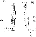
Fig. 2 is the schematic representation of this embodiment's metal bearing lining;
Fig. 3 is a width of cloth schematic representation, and it has illustrated the axial-flow fan motor of the metal bearing motor that is equipped with present embodiment;
Fig. 4 is a width of cloth schematic representation, and it has represented each manufacturing procedure (with each manufacturing procedure of the press process of advancing) of this embodiment's metal bearing lining;
Fig. 5 is a width of cloth sectional view, and it has illustrated the incision in the side of bottom in the manufacturing procedure (manufacturing procedure of the press process of advancing) of metal bearing lining of present embodiment;
Fig. 6 is a width of cloth sectional view, and it has illustrated the incision in the side on top in the manufacturing procedure (manufacturing procedure of the press process of advancing) of metal bearing lining of present embodiment;
Fig. 7 is a width of cloth sectional view, and it has illustrated common axial-flow fan motor, and this motor configurations has the metal bearing lining by the cutting moulding; And
Fig. 8 is a width of cloth sectional view, and it has illustrated common metal bearing lining by cutting forming.
Embodiment
To Fig. 6 the axial-flow fan motor that metal bearing of the present invention served as a contrast and be furnished with this bearing bush is described below in conjunction with Fig. 1.Introduce the metal bearing lining 2 of present embodiment at first briefly.A metal bearing lining 2 is performed its embedding mould (see figure 3) to the motor casing that is formed from a resin 3 of axial-flow fan motor 1.The technology that is called as the press process of advancing is meant that this press process of advancing is carried out press process to the sheet material of advancing in order.Therefore cutting (Fig. 8) that can be common and with the method moulding bearing bush 2 of press process, keep necessary accuracy simultaneously with this, has reduced metal bearing significantly and has served as a contrast 2 processing cost.
Below, the metal bearing that describes present embodiment in detail serves as a contrast 2.As shown in Figure 2, the metal bearing of present embodiment lining 2 cylindrical shapes that are processed to roughly.It is furnished with flange 4 on the edge of bottom sides (this limit will be embedded in the motor casing 3 of axial-flow fan motor 1), some recesses 5 (in an embodiment, being arranged in four positions) are arranged on this flange 4.And the inner circumferential surface 6 of bearing bush 2 is determined according to predetermined geometric tolerances (as circularity and cylindricity).The outer ring of the pair of bearings 7,8 of the rotating part of supporting axial-flow fan motor 1 (see figure 3) is assembled on the inner circumferential surface 6.
And, in the some top of moulding ring-type protruding part 13 (being arranged in the present embodiment on three positions) on the inner circumferential surface 6 and some bottoms circular protrusion part 14 (being arranged in the present embodiment on three positions), two kinds of projections will describe in detail it later on all by punch die 9 to 12 moulding of processing side notch (seeing Fig. 5 and 6).The metal bearing lining 2 of present embodiment has a kind of like this structure, wherein, makes the stop surface 13a of the outer ring (see figure 3) of the bearing 8 that inserts from the top of inner circumferential surface 6 near some upper ledge 13.Also make the stop surface 14a of the outer ring (see figure 3) of the bearing 7 that inserts from the bottom of inner circumferential surface 6 near some lower protrusion 14.Like this, be held one section predetermined spacing between the pair of bearings 7,8.
As shown in Figure 1, two edges on bearing bush 2 tops are by chamfering die device (not showing among the figure) chamfering, so that bearing 7 can easily be inserted into from top.And, see Fig. 2, at the corresponding relative side shaping groove 15 of the projection 13,14 of bearing bush 2, and projection 13,14 is with punch die 9 to 12 machine shapings of processing side notch (seeing Fig. 5 to 6).
Below, general description is furnished with the axial-flow fan motor 1 of the metal bearing lining 2 of present embodiment.The parts identical with parts in above-mentioned common axial-flow fan motor 21 (see figure 7)s are denoted as identical reference character, like this, will be omitted the explanation of those parts.As shown in figs. 1 and 3, the axial-flow fan motor 1 of present embodiment is furnished with the motor casing 3 that resin is made, and with respect to this shell 3, metal bearing lining 2 carries out embedding mould.Because metal bearing lining need not be common the cutting moulding, and use the press process moulding, reduced the cost of bearing bush 2 significantly, this makes the processing cost of axial-flow fan motor 1 be lowered.
The axial-flow fan motor 1 of detailed hereafter present embodiment.As shown in figs. 1 and 3, at the middle part of the motor casing 3 that is formed from a resin, with sleeve 16 of motor casing moulding integrally.The bottom of metal bearing lining 2, it is directed so that carry out embedding mould with respect to sleeve 16 by top press process (press process of advancing) moulding.Correspondingly, be embedded into the inner circumferential surface of sleeve 16 at the flange 4 of bottom moulding.This can stop bearing bush 2 to split away off (moving vertically) from motor casing 3.Some recesses 5 that are arranged on the flange 4 can also stop the rotation (see figure 2) of bearing bush 2 around its center line.
And as shown in figs. 1 and 3, on the axial-flow fan motor of present embodiment, sleeve 16 extends to the height place of the stop surface 14a of lower protrusion portion 14.When carrying out bearing bush 2 for the embedding mould technology of motor casing 3, resin is infused in the groove 15 of opposite side moulding of lower protrusion 14, like this, can stop bearing bush 2 to split away off (moving vertically), can also stop the rotation of bearing bush 2 round center line from motor casing 3.Sleeve 16 also can further be stretched over the height that covers groove 15.
Below, referring to Fig. 4, the course of working of the metal bearing lining of present embodiment is described in order.
(a) side cut operation
The side cut operation is carried out window formula perforation (window punching) with moulding cross-piece 20 according to positioning hole 17, this cross-piece connects housing 18 and inside casing 19 (seeing the operation (q) among Fig. 4), and positioning hole 17 processes by using trimming die (not showing among the figure) to go up perforation at a sheet material (coiled material).
(b) cutting process
The external frame of cutting process cutting cross-piece 20 and inside casing 19, this cross-piece and inside casing will be drawn processing in follow-up operation.
(c)-(h) drawing operation
In drawing operation, inside casing 19 is drawn processing so that one of moulding has the cylindrical shape of bottom, and this cylindrical shape has flange at its opening.Passing through execution in the press process process of the deep-drawing operation (drawing coefficient 25%) of inside casing 19, the inner circumferential surface 6 desired geometric tolerances (as circularity and cylindricity) of bearing bush 2 can be implemented, and this deep-drawing operation is divided into six workshop sections.In this embodiment, drawing operation is divided into six workshop sections, in these workshop sections, thereby carries out deep-drawing processing manufacturing metal bearing lining 2 with 25% drawing coefficient, so that obtain the precision of necessary inner circumferential surface 6.Notice that the quantity of workshop section and drawing coefficient are not limited to above-mentioned numerical value.
(i) molding procedure
After drawing operation, molding procedure is carried out the completion moulding of bearing bush 2.Then, the final size (precision) of the inner circumferential surface 6 of bearing bush 2 is done.
(j) punching operation
The punching operation is finished the punching to the bottom of bearing bush 2, and this bearing bush is shaped to the cylindrical shape that has the bottom in drawing operation.
(k) operation of burring
The edge section (not showing) of the punching of the bearing bush 2 after the moulding of punching operation be aduncate (along bearing bush 2 axially on).Correspondingly, by the mould that burs (not showing), the edge section of the bending of the bearing bush 2 of moulding in the punching operation is flattened.
(l) trimming process step
There is a shear surface edge section of the annular of the bearing bush 2 that flattens in the operation of burring, has the bellows-shaped that is caused by the punching operation on this shear surface.Correspondingly, in trimming process step, use a trimming die (not showing), on its surface of two edges all by moulding (deburring in cutting process).Like this, when carrying out the embedding mould technology of the motor casing 3 that 2 pairs of resins of bearing bush make, make the end of bearing bush 2 of present embodiment can easily be inserted in the bearing bush compatible portion of mould of a clamping bearing bush.In addition, upper bearing 7 (see figure 3)s can easily be inserted on the inner circumferential surface 6, so that carry out the assembling of bearing 7.
(m) correcting process
Correcting process is used a straightening die distortion that produces on the bearing bush 2 is proofreaied and correct, and these distortion are caused by trimming process step.
(n) side operation (bottom)
As shown in Figure 5, in side notch operation (bottom), form lower protrusion portion 14 by the punch die 9,10 that is used for the side notch on bearing bush 2, by driving a cam mechanism (not showing), punch die 9,10 is adjacent to each other or leave along the vertical direction among Fig. 5.As shown in Figure 5, three lower protrusion portions 14 are not that spacing distributes equably round the axis of bearing bush 2.Lower protrusion portion 14 and stop surface 14a are occurred crackle so that prevent by slitting-up on inner circumferential surface 6.Accordingly, seal, flow on the inner circumferential surface 6 so that prevent to be injected into the resin of the groove of the relative side that is positioned at lower protrusion portion 14.Like this, the end surface that makes bearing is reliably near stop surface 14a, so that realize accurately location.This also is applicable to upper ledge portion 13 and stop surface 13a.
(o) side notch operation (top)
As shown in Figure 6, in side notch operation (top), by punch die 11, the 12 moulding upper ledge portion 13 on bearing bush 2 that is used for moulding upper ledge portion, by driving a cam mechanism (not showing among the figure), punch die 11,12 is adjacent to each other or leave along the vertical direction among Fig. 6.As shown in Figure 6, three upper ledge portions 13 are not that spacing is arranged equably round the center line of bearing bush 2.
(p) go out operation
Going out operation, using a predetermined punch die (not showing), be distributed in recess 5 on the flange 4 of bearing bush 2 by moulding.Bearing bush 2 is also rushed out from inside casing 19, and the metal bearing gone out lining 2 is stored in accumulator (not showing) as a product.
(q) waste material cutting process
At the waste material cutting process with a waste material cutting mould (not showing) waste cut materials part.
By make in order the sheet material (coiled material) of advancing through side cut operation, cutting process, drawing operation, molding procedure, punching operation, the operation of burring, trimming process step, correcting process, side notch operation (bottom and top), go out operation and waste material cutting process, the metal bearing lining of present embodiment is processed to come out.This makes the method moulding can use press process normally with metal bearing lining 25 (the seeing Fig. 7 and 8) of milling process machine shaping and make its maintenance necessary accuracy (circularity, cylindricity and other).
The metal bearing lining 2 and the corresponding operation that is equipped with the axial-flow fan motor of this bearing bush of the structure that detailed hereafter is above-mentioned.By in order the sheet material (coiled material) that sequentially sends being carried out some press process operations, the metal bearing lining of present embodiment is by moulding.This make can be common by the method (seeing Fig. 7 and 8) of milling process forming metal bearing bush and with press process technology (the press process technology of advancing) forming metal bearing bush 25, and make it keep necessary accuracy (circularity, cylindricity and other), cause the processing cost of metal bearing lining to be considerably reduced, so that satisfy a large amount of requirements of producing metal bearing lining 2.
Be shaped to the upper ledge 13 of bearing 7 location of inserting from top and be the lower protrusion 14 of bearing 8 location of inserting from the bottom on the inner circumferential surface 6 of metal bearing lining 2, this metal bearing lining has cylindrical shape roughly.Above-mentioned upper ledge 13 and lower protrusion 14 work to give bearing 7,8 axially locating along bearing bush 2.
And the metal bearing lining 2 of present embodiment has flange 4 in its bottom, forms recess 5 on the edge of flange 4.When carrying out the embedding mould of the motor casing 3 that metal bearing lining 2 makes for resin, flange 4 is embedded in the sleeve 16 of motor casing 3, to stop coming off of bearing bush 2.The recess 5 of moulding on flange 4 plays a part to stop bearing bush 2 to rotate.
The embedding mould of the motor casing of making for resin by metal bearing lining 23, bearing bush 2 are implanted in the resins control in the groove 15 of back side moulding of lower protrusion 14 for the action of motor casing 3.Thus, metal bearing lining 2 comes off and rotates and can be prevented from.
When 25 pairs of motor casings of metal bearing lining carry out embedding mould, make its press process through advancing, in this press process process, the sheet material (coiled material) to production line carries out some press process operations in order, and need not to carry out common cutting.Therefore, can reduce the processing cost of metal bearing lining 2 significantly, reduce the manufacture cost of the axial-flow fan motor of the metal bearing lining 2 of being furnished with present embodiment with this.
Claims (2)
1. a metal bearing serves as a contrast, and forming substantially is cylindrical shape, and forms one with a resin motor casing through embedding mould, and described metal bearing lining comprises:
An inner circumferential surface is assembled by this surface pair of bearings, with an axle of supporting rotating part;
A plurality of juts are formed on described inner circumferential surface, so that make described pair of bearings location with predetermined interval;
A plurality of grooves are formed on the external peripheral surface that described metal bearing serves as a contrast, and described groove is carried out embedding mould technology directly upwards corresponding to described jut by resin being injected described a plurality of groove, and the metal bearing lining is nested together with the resin motor casing.
2. metal bearing lining as claimed in claim 1 is characterized in that also comprise a flange portion, this flange portion has a plurality of recesses, rotates with respect to motor casing to prevent the metal bearing lining.
Applications Claiming Priority (2)
| Application Number | Priority Date | Filing Date | Title |
|---|---|---|---|
| JP2000356176A JP4461311B2 (en) | 2000-11-22 | 2000-11-22 | Axial fan motor |
| JP356176/2000 | 2000-11-22 |
Publications (2)
| Publication Number | Publication Date |
|---|---|
| CN1354330A CN1354330A (en) | 2002-06-19 |
| CN1201098C true CN1201098C (en) | 2005-05-11 |
Family
ID=18828469
Family Applications (1)
| Application Number | Title | Priority Date | Filing Date |
|---|---|---|---|
| CNB011303891A Expired - Fee Related CN1201098C (en) | 2000-11-22 | 2001-11-22 | Metal bearing liner and axial-flow fan motor with said bearing liner |
Country Status (6)
| Country | Link |
|---|---|
| US (1) | US6729764B2 (en) |
| EP (1) | EP1211431B1 (en) |
| JP (1) | JP4461311B2 (en) |
| CN (1) | CN1201098C (en) |
| DE (1) | DE60130090T2 (en) |
| TW (1) | TW507052B (en) |
Cited By (1)
| Publication number | Priority date | Publication date | Assignee | Title |
|---|---|---|---|---|
| CN103161808A (en) * | 2011-12-12 | 2013-06-19 | 东莞市三创五金塑胶有限公司 | Fixing piece and manufacturing method thereof |
Families Citing this family (18)
| Publication number | Priority date | Publication date | Assignee | Title |
|---|---|---|---|---|
| US6900961B1 (en) * | 2002-08-30 | 2005-05-31 | Western Digital Technologies, Inc. | Disk drive having a head disk assembly enclosure including insert molded components |
| CA2459237C (en) * | 2003-03-01 | 2009-05-19 | Truth Hardware Corporation | Operator assembly |
| DE50307183D1 (en) * | 2003-10-21 | 2007-06-14 | Siemens Ag | Storage device, in particular for a transmission |
| CN1957184B (en) * | 2004-03-30 | 2011-05-25 | Ntn株式会社 | Fluid dynamic pressure bearing device |
| CN100387857C (en) * | 2004-08-11 | 2008-05-14 | 洛阳轴承集团有限公司 | Method for finishing inner surface of babbit layer of film bearing lining |
| CN100453819C (en) * | 2005-03-18 | 2009-01-21 | 台达电子工业股份有限公司 | Fan casing |
| JP4857631B2 (en) * | 2005-07-15 | 2012-01-18 | 日本電産株式会社 | Fan motor |
| JP4747754B2 (en) * | 2005-09-16 | 2011-08-17 | 日本電産株式会社 | motor |
| US20080247689A1 (en) * | 2007-04-06 | 2008-10-09 | Nidec Corporation | Motor |
| DE102008015154A1 (en) * | 2007-05-15 | 2008-11-20 | Schaeffler Kg | Guide or tensioning rail in a traction drive |
| JP4946625B2 (en) * | 2007-05-21 | 2012-06-06 | 日本電産株式会社 | motor |
| ITMC20080007A1 (en) | 2008-01-16 | 2009-07-17 | Meccanica Generale Srl | METHOD FOR THE CONSTRUCTION OF A PRESSED SHEET BEARING HOLDER. |
| US20100007205A1 (en) * | 2008-07-14 | 2010-01-14 | Caterpillar Inc. | Self-lubricated track roller assembly and machine using same |
| JP5668534B2 (en) | 2011-03-08 | 2015-02-12 | 日本電産株式会社 | Blower fan |
| CN111173840B (en) | 2015-06-30 | 2021-10-26 | 美国圣戈班性能塑料公司 | Sliding bearing |
| DE102017112983A1 (en) * | 2017-06-13 | 2018-12-13 | Ebm-Papst Mulfingen Gmbh & Co. Kg | Blower housing part with bearing support and blower |
| CA3014621A1 (en) | 2017-08-21 | 2019-02-21 | Truth Hardware Corporation | Integrated casement window operator and lock with anti-backdrive feature |
| CN112228478A (en) * | 2020-10-22 | 2021-01-15 | 华伍轨道交通装备(上海)有限责任公司 | Cylinder liner and preparation method thereof |
Family Cites Families (8)
| Publication number | Priority date | Publication date | Assignee | Title |
|---|---|---|---|---|
| US3924908A (en) | 1973-12-07 | 1975-12-09 | Unex Conveying Systems Inc | Roller with inserted ball bearings |
| AU5265479A (en) | 1978-11-13 | 1980-05-22 | Tubemakers Of Australia Limited | Axle tube construction |
| JPH0449372Y2 (en) * | 1985-05-23 | 1992-11-20 | ||
| FR2600838A1 (en) | 1986-06-27 | 1987-12-31 | Etri Sa | ELECTRIC MOTOR WITH PERFECTED BEARING |
| DE3809277B4 (en) | 1987-09-21 | 2005-02-24 | Papst Licensing Gmbh & Co. Kg | Bearing arrangement for axially compact micro fan |
| JP2522984Y2 (en) * | 1990-07-13 | 1997-01-22 | 株式会社三ツ葉電機製作所 | Bearing structure of wiper arm |
| DE4224817A1 (en) | 1992-07-27 | 1994-02-03 | Electro Pneumatic Int | Transport roller for rolling belt in aircraft storage hold - has inner seats for ball bearings formed in sleeve casing by moulding without material-weakening stock removal |
| JP2000179535A (en) * | 1998-12-16 | 2000-06-27 | Honda Motor Co Ltd | Bearing metal positioning structure in split type connecting rod |
-
2000
- 2000-11-22 JP JP2000356176A patent/JP4461311B2/en not_active Expired - Fee Related
-
2001
- 2001-11-13 US US09/987,174 patent/US6729764B2/en not_active Expired - Lifetime
- 2001-11-16 TW TW090128483A patent/TW507052B/en not_active IP Right Cessation
- 2001-11-19 DE DE60130090T patent/DE60130090T2/en not_active Expired - Lifetime
- 2001-11-19 EP EP01127536A patent/EP1211431B1/en not_active Expired - Lifetime
- 2001-11-22 CN CNB011303891A patent/CN1201098C/en not_active Expired - Fee Related
Cited By (1)
| Publication number | Priority date | Publication date | Assignee | Title |
|---|---|---|---|---|
| CN103161808A (en) * | 2011-12-12 | 2013-06-19 | 东莞市三创五金塑胶有限公司 | Fixing piece and manufacturing method thereof |
Also Published As
| Publication number | Publication date |
|---|---|
| EP1211431B1 (en) | 2007-08-22 |
| US20020061145A1 (en) | 2002-05-23 |
| DE60130090T2 (en) | 2008-05-21 |
| US6729764B2 (en) | 2004-05-04 |
| EP1211431A1 (en) | 2002-06-05 |
| JP2002155939A (en) | 2002-05-31 |
| TW507052B (en) | 2002-10-21 |
| JP4461311B2 (en) | 2010-05-12 |
| DE60130090D1 (en) | 2007-10-04 |
| CN1354330A (en) | 2002-06-19 |
Similar Documents
| Publication | Publication Date | Title |
|---|---|---|
| CN1201098C (en) | Metal bearing liner and axial-flow fan motor with said bearing liner | |
| CN1297756C (en) | Liquid bearing device | |
| CN1797909A (en) | Spindle motor | |
| CN1848614A (en) | Magnet embedded motor, rotor unit and producing method of rotor unit | |
| CN101039055A (en) | Method for manufacturing a stator core of an axial air-gap motor | |
| CN1933292A (en) | Bearing retainer unit and electric motor furnished therewith | |
| CN1638233A (en) | Motor for washing machine | |
| CN1741353A (en) | Axial air-gap electronic motor | |
| CN1767331A (en) | Brushless motor | |
| CN1957516A (en) | Fluid dynamic pressure bearing device and motor using the same | |
| US11437875B2 (en) | Motor shaft, rotor, motor and blower | |
| CN1203261C (en) | Mfg. method of thrust plate and mfg. method of shaft for fluid power bearing | |
| CN101764446A (en) | Motor stator and manufacturing method thereof | |
| CN106374667B (en) | Automobile micromotor shell | |
| CN107528414A (en) | Motor | |
| CN1310510A (en) | Rotor of whirler and its producing method | |
| CN1621198A (en) | Manufacturing method for cylindrical part | |
| CN1086932A (en) | Cylinder type anisotropic magnets and manufacture method thereof and motor | |
| CN106329802A (en) | Automobile micromotor shell and manufacturing method thereof | |
| CN1265527C (en) | DC electric motor | |
| CN114985568A (en) | Double-row 42-step stator-rotor iron core sleeve punching progressive die | |
| CN1602574A (en) | Method for manufacturing flat commutator and its manufacturing system | |
| JPH08205453A (en) | Magnetic disc drive | |
| CN211588150U (en) | Production mould of bearing frame | |
| JP3544114B2 (en) | Manufacturing method of stepping motor |
Legal Events
| Date | Code | Title | Description |
|---|---|---|---|
| C06 | Publication | ||
| PB01 | Publication | ||
| C10 | Entry into substantive examination | ||
| SE01 | Entry into force of request for substantive examination | ||
| C14 | Grant of patent or utility model | ||
| GR01 | Patent grant | ||
| CF01 | Termination of patent right due to non-payment of annual fee |
Granted publication date: 20050511 Termination date: 20171122 |
|
| CF01 | Termination of patent right due to non-payment of annual fee |