CN1179101C - Sheet-like masonry block drainage system - Google Patents
Sheet-like masonry block drainage system Download PDFInfo
- Publication number
- CN1179101C CN1179101C CNB008044570A CN00804457A CN1179101C CN 1179101 C CN1179101 C CN 1179101C CN B008044570 A CNB008044570 A CN B008044570A CN 00804457 A CN00804457 A CN 00804457A CN 1179101 C CN1179101 C CN 1179101C
- Authority
- CN
- China
- Prior art keywords
- drainage system
- water blocking
- blocking tape
- masonry
- drainage
- Prior art date
- Legal status (The legal status is an assumption and is not a legal conclusion. Google has not performed a legal analysis and makes no representation as to the accuracy of the status listed.)
- Expired - Fee Related
Links
Images


Classifications
-
- E—FIXED CONSTRUCTIONS
- E02—HYDRAULIC ENGINEERING; FOUNDATIONS; SOIL SHIFTING
- E02D—FOUNDATIONS; EXCAVATIONS; EMBANKMENTS; UNDERGROUND OR UNDERWATER STRUCTURES
- E02D29/00—Independent underground or underwater structures; Retaining walls
- E02D29/02—Retaining or protecting walls
- E02D29/0258—Retaining or protecting walls characterised by constructional features
- E02D29/0266—Retaining or protecting walls characterised by constructional features made up of preformed elements
-
- E—FIXED CONSTRUCTIONS
- E04—BUILDING
- E04B—GENERAL BUILDING CONSTRUCTIONS; WALLS, e.g. PARTITIONS; ROOFS; FLOORS; CEILINGS; INSULATION OR OTHER PROTECTION OF BUILDINGS
- E04B1/00—Constructions in general; Structures which are not restricted either to walls, e.g. partitions, or floors or ceilings or roofs
- E04B1/62—Insulation or other protection; Elements or use of specified material therefor
- E04B1/70—Drying or keeping dry, e.g. by air vents
-
- E—FIXED CONSTRUCTIONS
- E02—HYDRAULIC ENGINEERING; FOUNDATIONS; SOIL SHIFTING
- E02D—FOUNDATIONS; EXCAVATIONS; EMBANKMENTS; UNDERGROUND OR UNDERWATER STRUCTURES
- E02D31/00—Protective arrangements for foundations or foundation structures; Ground foundation measures for protecting the soil or the subsoil water, e.g. preventing or counteracting oil pollution
- E02D31/02—Protective arrangements for foundations or foundation structures; Ground foundation measures for protecting the soil or the subsoil water, e.g. preventing or counteracting oil pollution against ground humidity or ground water
-
- E—FIXED CONSTRUCTIONS
- E02—HYDRAULIC ENGINEERING; FOUNDATIONS; SOIL SHIFTING
- E02D—FOUNDATIONS; EXCAVATIONS; EMBANKMENTS; UNDERGROUND OR UNDERWATER STRUCTURES
- E02D2600/00—Miscellaneous
- E02D2600/20—Miscellaneous comprising details of connection between elements
Landscapes
- Engineering & Computer Science (AREA)
- Structural Engineering (AREA)
- Architecture (AREA)
- Civil Engineering (AREA)
- Life Sciences & Earth Sciences (AREA)
- Environmental & Geological Engineering (AREA)
- Physics & Mathematics (AREA)
- Electromagnetism (AREA)
- General Life Sciences & Earth Sciences (AREA)
- Mining & Mineral Resources (AREA)
- Paleontology (AREA)
- General Engineering & Computer Science (AREA)
- Hydrology & Water Resources (AREA)
- Retaining Walls (AREA)
- Building Environments (AREA)
Abstract
A masonry block drainage system (10) comprising a sheet-like waterproofing strip (12) for water-sealing the top of the masonry blocks (6) having vertically-extending cavities (8), at least one drainage fabric member (20), and at least one weep member (30) for draining water from the drainage fabric member (20).
Description
Technical field
The present invention relates to a kind of be used for collecting a masonry piece within the walls the chamber percolating water and described percolating water is discharged into the drainage system of a position of outside, described masonry piece chamber from the inner chamber of described masonry piece wall.
Background technology
The masonry piece is because of making water on the wall outside by the seam between the masonry piece or itself to enter into its center cavity by the masonry piece very unfavorable.After water enters into described masonry piece chamber, can make water be penetrated into interior of building and bring moisture issues.In described masonry piece and interior wall and the exterior wall of their lip-deep water after may making completion impaired.
People have proposed several schemes and have solved problem by masonry piece wall percolating water.For example, a kind of scheme is to use the masonry piece with opening so that the water in the masonry piece chamber is discharged into a layer of gravel in bottom, then makes water enter into a field tile.Such system is disclosed in the U.S. Pat 4,612,742 of the U.S. Pat 4,333,281 of Scarfone and Bevilacqua.
Another kind of scheme is to utilize the bottom that the masonry piece is placed on the transverse groove with interconnection to solve the problem of percolating water, and the transverse groove of described interconnection can make water laterally be discharged in the adjacent masonry piece.Then utilize a drainage pipe that stretches out from one of them masonry piece (as U.S. Pat 3 at Parezo, 562, disclosed in 982) or utilize and be arranged on the opening that is used in the bottom masonry piece that water caused a layer of gravel and then water can be caused a field tile (as the U.S. Pat 4 at Cosenza, disclosed in 486,986) water is discharged into the outside of described masonry piece wall.
Another kind of scheme is to utilize a thin discharge structure spare is arranged on the following of described bottom brick rock layer then water is caused the problem that a field tile solves percolating water water is caused a layer of gravel.Such as U.S. Pat 4,383 at Koester, disclosed in 630.
A shortcoming of above-mentioned drainage system is, when water discharged downwards by described masonry piece chamber downwards, above-mentioned drainage system can not prevent that the water in the described masonry piece chamber from contacting with the internal chamber wall of described masonry piece and permeate.Must pass through described internal chamber wall from upper stream to the water of lower floor, thereby make such wall by water saturates, this can make water be penetrated on the inner surface and external surface of described building usually.U.S. Pat 2 at Henderson, 147, disclose a kind of method that is used to avoid this problem in 035, be about to asphalt paper that a middle part has open-work and be inserted in the vertical gap in described masonry piece percolating water is caused the center in described gap from outer wall.Then in masonry piece place's draining of described bottom, water can be guided the outside into and also can inwardly cause one and is positioned at following base plate place by the hole in the described masonry piece there.
In addition, another shortcoming of above-mentioned some of them drainage system is that they arrange water to the inside of described building, rather than water is deflected from described interior of building and guides the outside into.Such system can impel the ground that is positioned at below described wall and the building by water saturates.And installation layer of gravel and field tile are difficult below described building.
Another problem of above-mentioned some of them drainage system is that they can not collect water at a level height place that is different from described bottom from described masonry piece chamber.Therefore, the water that enters into a masonry piece wall at upper strata place must pass through internal chamber wall and flow into bottom before discharge.Like this, water can contact and penetrate into by described masonry piece the inside of described building naturally with the masonry piece.Like this, U.S. Pat 4 as Pardue, 910, disclose in 931, use the system with upper water catch tray, described upper water catch tray has from a series of lower catch tray of fluid groove below water collected the described dish is discharged into by the vertical chamber of masonry piece in the brick rock layer of bottom that outfall is wherein drawn.Nethermost a series of described bottoms catch tray is then collected from the water of top catch tray by the vertical chamber discharging of masonry piece, utilizes the percolating water chute that crosses out from described bottom catch tray will be discharged into the outside of described wall at the water the catch tray of described bottom then.But one of them where the shoe pinches of known these kinds drain pan system is, must make described dish and masonry piece chamber consistent.That is, described dish must be made into the shape that conforms to specific masonry piece and have the size that conforms to specific masonry piece chamber with other parts in the described drainage system.This is very inconvenient for masonry piece user, masonry piece user must extreme care so that the described drainage system that cooperates with the masonry block structure can correctly be installed.
According to existing shortcoming in the prior art, people need a kind of masonry block drainage system new and that have creativity.
Summary of the invention
In order to overcome existing shortcoming in the prior art, the invention provides a kind of new sheet-like masonry block drainage system of being convenient to and being easy to make and using.
A kind of masonry block drainage system involved in the present invention comprises: a sheet water blocking tape that is used for a masonry piece is carried out water-stop has at least one vertically extending chamber in the described masonry piece; At least one draining fabric component; And at least one is used for the element that drips that water is discharged from described draining fabric component.
Preferably a kind of sheet material of reeling of described water blocking tape, it can be made by polyolefin or other material, and its width should be enough to the vertical extended cavity that anti-sealing enters into described masonry piece.Described water blocking tape has the device that a kind of waterproof sealing is provided around being used in described masonry piece chamber, such as a kind of water-proof adhesive or a kind of be used for be applied in described masonry piece top on greensand starch the connected structure that combines.Preferably utilize a kind of cementing agent that described draining fabric component is linked to each other with described water blocking tape or make it to be embedded in the described water blocking tape, and utilize the element that drips to discharge percolating water, described a plurality of elements that drip are preferably separated in the mode that keeps a determining deviation mutually along the side of described water blocking tape.Water is discharged into a position in outside, described masonry piece chamber from described draining fabric component.
What related here masonry block drainage system and device preferably can be reeled is mounted so that can make them be easy to be transferred and be easy at the construction field (site).Like this, the width of adjusting described water blocking tape and draining fabric component is to be relatively easy to, and such as the mode of utilizing cutting, thereby is convenient to install at the scene.Sometimes can produce described masonry block drainage system and make them be applicable to the masonry piece of different shape by the multiple standards width.Use with the common draining fabric component that extends of water blocking tape to make percolating water be collected and be assigned to more than on the element that drips, described draining fabric component preferably adheres on the described water blocking tape or is connected thereto.Even owing to can improve drainage speed and also percolating water can be discharged from masonry piece chamber when some elements that drip are stopped up by dust, chip or masonry piece mortar, so this is very useful.
Another advantage of the present invention is, need not in masonry piece boring or in masonry piece chamber or each brick rock layer or bottom masonry piece below complexity is set and expensive pipeline or structural member can make percolating water flow to another masonry piece chamber from a masonry piece chamber in the mode that laterally moves.Other features and advantages of the present invention as can be seen from the following description.
Description of drawings
Now with reference to the accompanying drawings the preferred embodiments of the present invention are described in detail, in the accompanying drawings:
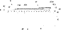
Fig. 1 is the phantom drawing of an embodiment of masonry block drainage system involved in the present invention, and wherein said drainage system can be adhered on the top of the masonry piece with vertical inner chamber;
Fig. 2 is a sectional view when masonry block drainage system shown in Fig. 1 is being adhered to appropriate position on the top of masonry piece;
Fig. 3-6 shows the sectional view of other embodiment of masonry block drainage system involved in the present invention; And
Fig. 7 is a top plan view of masonry block drainage system involved in the present invention.
The detailed description of embodiment
An embodiment of a kind of masonry block drainage system 10 involved in the present invention has been shown among Fig. 1, described masonry block drainage system 10 can be configured to the form of a volume 11, described volume 11 can launch at the construction field (site) and can directly be adhered on the top of a brick rock layer 6, and described masonry piece has the chamber 8 of vertical extent (or orientation).The masonry piece is generally used for building body of wall and other building structure.
A masonry block drainage system 10 comprises a water blocking tape 12, described water blocking tape 12 is the plates that a substantitally planar extends, described plates are included in described with one first interarea that extends between the crimping 14 and 16 of 12 longitudinal extension (direction one side down when installing) and one second interarea (one side that is directed upwardly when the installation as shown in FIG.).
Described water blocking tape 12 has the device that can form water-stop around the chamber 8 of described masonry piece 6, such as on first interarea of described water blocking tape 12, adhering to a kind of pressure-sensitive water-proof adhesive 18 described draining set composite 10 being connected to the top of masonry piece, thus the vertical cavity 8 that anti-sealing enters described masonry piece.Like this, described width with 12 should be slightly larger than the width in the chamber 8 of described masonry piece, and preferably less than the width of described masonry piece 6, so that after will being installed in the top of described masonry piece 6, can use mortar so that described brick rock layer and next brick rock layer are bonded together along the side of described band with 12.
Preferably a kind of continuous sheet of making by plastics, paper, metal, glass or its combined material of described water blocking tape 12.Preferably use a kind of such as polyethylene and polyacrylic polyolefin.It is preferred that a kind of polyolefin sheets is used in combination with a kind of asphalitine water-proof adhesive 18.
Can use known pressure-sensitive water-proof binding agent material, such as the asphalitine cementing agent of asphalitine cementing agent, modified rubber, non-asphaltic synthetic binder (for example, styrene-isoprene-phenylethene, butadiene-styrene rubber, Ethylene Propylene Terpolymer monomer rubber) or its mixture, so pressure-sensitive water-proof binding agent material can use on one of them interarea of described water blocking tape 12 or on two interareas.For example, a kind of water-proof adhesive layer of routine or be with 18 can be coated or be laminated on the plastic sheeting, obtaining described water blocking tape 12, and can be set to a pantostrat that extends to another longitudinal edge (16) from a longitudinal edge (14) of described water blocking tape 12.
The liner that can get loose 19 is used to protect described water-proof adhesive layer 18; the described liner that gets loose 19 can be made by siliconised paper or paraffin paper or plastics, removes the described liner that gets loose 19 in the mode of using before the described water-proof adhesive layer 18 or peel off such as utilization when launching described dewatering installation 10 on described masonry piece 6.
Also show a draining fabric component 20 (when installing, being positioned at like this, the top of described water blocking tape 12) on first interarea that is set at described water blocking tape 12 among Fig. 1.The form of described draining fabric component 20 is preferably along with described with the sheet of 12 longitudinal extensions or similar form (that is, it is flat and can reels).The width of described draining fabric component 20 is with described identical or less than with 12 width with 12, shown draining fabric component 20 is a kind of webbing, be preferably supatex fabric, the purpose that draining fabric component 20 is set prevents to be stopped up by dust, chip or mortar (dropping into the chamber of the brick rock layer of then installing) for water is discharged from the inner chamber of (then installing) masonry piece simultaneously.Preferred supatex fabric is heavy felt or spunbond polyolefin or polyester, such as the fabric of the sort of type used in soil filtration fabrics and geotextile.The thickness of fabric depends on its density, and described thickness is more preferably greater than the 1-3 Mill.Thicker and/or heavier fabric is preferred, and this is because this means, the displacement of described draining fabric component 20 increases, even and when the mortar chance is fallen on the described fabric described fabric still can bring into play drainage.Like this, for example a kind of weight of supatex fabric can be 136 gram/square metre (4oz/yd
2) to 270 gram/square metre (8oz/yd
2).The upper surface that described draining fabric component 20 preferably adheres to (utilize cementing agent or glue-not shown), clinkering or otherwise is connected to described water blocking tape 12 occurs relatively moving avoiding between the two.
Described masonry block drainage system 10 comprises that also at least one links to each other with described draining fabric component 20 and extends to the element 30 that drips beyond the longitudinal extension edge 16 of described water blocking tape 12, and preferably has a plurality of elements that drip spaced apart from each other.Described effect of dripping element 30 provides a diversion passage so that can flow to a position away from described masonry piece chamber 8 by described draining fabric component 20 collected water, such as a position that flows on the external surface of described masonry piece 6.The element that drips is generally the slender bodies that has or define a diversion passage, and described slender bodies is towards extending away from the direction at the edge 16 of described longitudinal extension and away from described water blocking tape 12.Preferably the edge along described masonry piece dewatering installation 12 uses a plurality of elements 30 that drip spaced apart from each other.
For convenience's sake, the described element 30 that drips can integrally be made (as shown in fig. 1) by identical fabric sheet with draining fabric component 20.This can utilize following manner to finish simply, promptly, weave or 14 pairs of described fabric sheets 20 in longitudinal extension edge of nonwoven sheet 20 carry out the part cutting forming the element 30 that drips that extends from described, the formed element 30 that drips can extend to the outermost edge of described masonry piece when described device 10 correctly is installed on the chamber 8 of described masonry piece 6.Perhaps also webbing, rope, pipe, draining core or other diversion conduit can be arranged on the top and/or the below of the described element 30 that drips.The described element 30 that drips itself also can be used as independent parts and is connected, such as by heavy weave band (preferably non-woven), rope, rope or other mushy element being set on the edge of described draining fabric component 20, can make water leave described draining fabric component 20 like this and be discharged into a position in described brick rock layer 6 outsides with the longitudinal extension edge 16 of certain interval along described water blocking tape.The top that perhaps also a kind of undulatory band or other supporting construction can be arranged on the described element that drips to prevent because continuous administration mortar and/or masonry piece and collapsing of may causing.
In another embodiment of masonry block drainage system 10, second interarea that one second water-proof adhesive can be set at described water blocking tape 12 (as shown in the figure, the one side that is directed upwardly) on, like this, mortar cement can be on the longitudinal extension edge 22 of described water blocking tape 12 (being directed upwardly) second interarea and 24 places be applied to one deck masonry piece down (being applied on the one side up of the water blocking tape that masonry piece 6 that described part exposes and part expose).Described second water-proof adhesive is similar with described first water-proof adhesive aspect component, and when described mortar was applied on described second water-proof adhesive and makes described mortar hardening, described second water-proof adhesive was used to form a kind of mechanical bond.Described second water-proof adhesive can be a kind of along described be directed upwardly and the outward flange of longitudinal extension (as among the figure with shown in Reference numeral 22 and 24) cover fully as described in second interarea or only cover as described in the mode of a part of second interarea be applied in as described on second interarea of water blocking tape 12.Best, described second water-proof adhesive adopts a kind of form (as shown in Figure 2) of layer 40, and described layer 40 also can have a protection coat 42 (such as a kind of elastomeric layer) to protect described cementing agent.Described adhesive layer and coat are used for combining with the mortar of just having used, and the described mortar of just having used contacts with coat with described adhesive layer and can be hardened.Using a kind of coat 42 of protecting on asphalitine that is used for combining with concrete and mortar and non-asphaltene synthetic binder layer is known in this area, and in the U.S. Pat 4,994,328 of Cogliano; People's such as Bartlett U.S. Pat 5,316,848; And disclosed in people's such as Bartlett the U.S. Pat 5,496,615, all these documents are here as a reference.
As can be seen, masonry block drainage system 10 sticks on the described masonry piece 6 and is positioned at the top of the vertical cavity 8 of described masonry piece from cross-sectional view shown in Figure 2.The width of water blocking tape 12 between the longitudinal extension edge that has the described first water-proof adhesive layer 18 is slightly larger than the width of described vertical cavity 8 (best, less than the width of described masonry piece 6).The bandwidth of described draining fabric component 20 best (but this is not necessary) is less than the width of described water blocking tape 12, so that one second water-proof adhesive 40 can be used in the part 22 and 24 places of exposing in the water blocking tape and be directed upwardly, thereby described second water-proof adhesive 40 is combined with mortar 60 on the top surface that then is applied in described masonry piece 6.(for simplicity, only showing an edge 22 that is coated with mortar cement 60 among the figure).
As shown in Figure 2, the described element 30 best longitudinal extension edges along described water blocking tape 12 that drip extend and extend to outside the described longitudinal extension edge, can be from described draining fabric component 20 discharge percolating waters and the passage that described percolating water is directed to a position outside described masonry piece 6 edges thereby can be used as one.On the top surface that described mortar 60 is applied in described masonry piece 6 and be applied in be in described both direction up part 22 and the second water-proof adhesive layer 40 at 24 places on after, then another layer masonry piece can be placed into the appropriate position at described masonry piece 6 tops.
The protection coat 42 that is applied in the described second water-proof adhesive layer 40 of described part 22 and 24 place's (see figure 2)s and can selects to attach is used for combining with mortar and as can be seen from the figure is to be directed upwardly surperficial edge along described water blocking tape 12 to adhere to.
Another embodiment of masonry piece dewatering installation 10 has been shown among Fig. 3.The described second water-proof adhesive layer 40 (is preferably a kind of pressure-sensitive non-asphaltene synthetic binder, such as styrene-isoprene-phenylethene (SIS)) can be used as a kind of pantostrat and be applied on the surface that is directed upwardly of described water blocking tape 12, can be used for connecting described draining fabric component 20 like this.The described second water-proof adhesive layer 40 can be thicker at described outer edge part 22 and 24 places in case can increase with in these positions (for example, at described outer edge part 22 and 24 places) use and the living mortar cement that makes it to harden forms a kind of possibility of mechanical bond, but this is not necessary.The element 30 that drips shown in Fig. 3 be make by a kind of independent piece of cloth and be set on the top of described draining fabric component 20; Believe that this is enough to guarantee provide one water is discharged into a diversion conduit that surpasses the position at described water blocking tape 12 edges from described draining fabric component 20, and described diversion conduit surpasses described masonry piece 6 and can extend to a position in 8 outsides, described masonry piece chamber.
Fig. 4 shows another embodiment of masonry piece dewatering installation 10 involved in the present invention, and wherein said draining fabric component 20 comprises and is bearing in a piece of cloth 20A on the hollow supporting member 20B.Preferably a kind of supatex fabric of described sheet material, and described hollow supporting member (for example preferably includes a corrugated plastic sheet, polypropylene or polyethylene), for example it has the frustum-like shape projection, and described piece of cloth 20A is to keep the mode of a determining deviation and described frustum-like shape projection to link together with described 20B.This hollow matrix preferably can make water flow on both direction, promptly vertically flows and flows transverse to described draining fabric component 20 along described draining fabric component 20.The combination of described fabric and hollow sheet (20A/20B) can obtain on market, for example by Grace ConstructionProducts, and Cambridge, Massachusetts is with HYDRODUCT
For trade mark is sold.This commercially available drainage products is configured to web-like usually.Can be along an edge a kind of like this trap drainage element be cut with the formation element that drips, perhaps can at the construction field (site) the described element that drips be added to from described HYDRODUCT
What the joint product cutting formed is with.Present known various composite, water-drain assemblies are for example in U.S. Pat 3,654,765; US 3,812, and 001; US 4,102, and 720; US4,572,700; US 4,574, and 541; US 4,614, and 000; US 4,631, and 221; US 4,662, and 778; US 4,733, and 989 and US 4,943, disclosed in 185, all these documents are here as ginseng person's document.
As can be seen, described draining fabric component 20A can also be that a kind of supatex fabric that is separated by a corrugated plastic sheet 12B (similar with corrugated cardboard) is so that described draining fabric component 20A and described water blocking tape keep certain spacing from sectional view shown in Figure 5.Fabric/corrugated material that the element 30 that drips can utilize with described filtration/sheet material 20A/20B is identical integrally forms.
Fig. 5 also shows another embodiment, and wherein a kind of first water-proof adhesive 18 and a kind of second water-proof adhesive 40 are configured to along the form of the band of the longitudinal extension edge extension of described water blocking tape 12.These cementing agents 18/40 can be taken off described strippable sheet band when using described cementing agent by the strippable sheet band (not shown) protection that gets loose.Described draining fabric component 20 comprise fabric 20A and can be set up in its lower section hollow member 20B (this hollow member 20B is not necessary) so that the described element 30 that drips be embedded in the described cementing agent 40 in a side, thereby preventing that described draining fabric component 20 from producing relatively moves.In this case, described hollow-core construction can prevent that the mortar that the fabric in the described element that drips is then used from stopping up.
Fig. 6 is the sectional view of another embodiment of dewatering installation 10 involved in the present invention, preferably is provided with tissue layer (preferably supatex fabric) on two interareas of wherein said water blocking tape 12.As the supatex fabric of described draining fabric component 20 can utilize be connected to described relative interarea on the supatex fabric identical materials make, and be connected to supatex fabric on the described relative interarea as a kind of connected structure 18 that is used on the chamber 8 of described masonry piece 6, providing a kind of waterproof sealing.For the dewatering installation 10 shown in installing, use one deck mortar cement (6) at the top of described brick rock layer 6 around described vertically extending chamber 8, then described device 10 is gone up at the top of described mortar cement 60 (and being embedded to wherein) and launched; Then one or more elements 30 that drip (also can be made by identical non-woven material) are arranged on the top of described device 10.(if the described element that drips is to utilize the sheet material identical with described trap drainage element 20 integrally to make, and at this moment this procedure will be omitted so).Then second layer mortar cement (60B) is applied on the outward flange of the top of described masonry piece 6 and described draining fabric component 20.Described mortar (60A and 60B) combines with described supatex fabric, preferably utilize a kind of water-proof adhesive of routine to make it to adhere on the described water blocking tape 12 or imbed wherein, described like this device 10 can be used for entering into the water of the vertical extended cavity 8 that is arranged in following masonry piece 6 and discharges.
An embodiment for described connected structure, except fabric (for example supatex fabric), comprise that also utilization can be connected on the described water blocking tape 12 or the fiber that becomes one with it or " fine hair ", even also can use enough coarse surface so that can engage with mortar." joint " structure like this is known in the waterproof field, believes that it is suitable for being combined with mortar that just used as that implement in the present invention.
Fig. 7 shows the plan view from above of a kind of masonry block drainage system 10 involved in the present invention in the chamber portion 8 that is installed in the masonry piece.The width of shown draining fabric component 20A is preferably less than the width of described water blocking tape 12 (for convenience of description, shown also can be narrower again).The element of representing with Reference numeral 30 that drips can comprise that inverted trade mark is the band of the drainage products (the soil filtration fabrics that links to each other with sharp core) of HYDRODUCT , and described inverted band is set on the longitudinal extension edge 16 of described device 10 and extends to beyond the edge of described masonry piece.
The foregoing description only is for present invention is described, all should drop in protection scope of the present invention its remodeling that carries out and variation under the premise of without departing from the spirit of the present invention.
Claims (19)
1. masonry block drainage system comprises:
A sheet water blocking tape that is used for a masonry piece is carried out water-stop, has at least one vertically extending chamber in the described masonry piece, described water blocking tape comprises the plates that cardinal principle is continuous, described water blocking tape plates are by a kind of polymeric material, paper, metal, glass or its combined material are made, described continuous plates have one first interarea and second interarea relative with described first interarea, described first interarea has a mode that is used for sealing and described water blocking tape plates is connected to pressure sensitive adhesives layer on the vertical extended cavity of a masonry piece, and described second interarea also has one and is used for a drainage component is connected to pressure sensitive adhesives layer on the continuous plates of described water blocking tape; And
The drainage component that at least one links to each other with described second interarea of described sheet water blocking tape, described drainage component comprises that one is weaved or supatex fabric and have first and second longitudinal edges, width between this first and second longitudinal edge is less than the width of described water blocking tape plates, described drainage component links to each other so that the part of described water blocking tape plates is not covered by described drainage component with described sheet water blocking tape, and the described part of exposing can combine with the mortar of pouring into a mould along first and second longitudinal edges of described drainage component; And
At least one is used for the element that drips that contacts with described at least one drainage component, thereby the water in described drainage component can be discharged from described water blocking tape plates.
2. drainage system as claimed in claim 1, it is characterized in that, described at least one pressure sensitive adhesives layer comprises a kind of bituminous material, a kind of non-asphaltic synthetic materials or its mixture, and described at least one pressure sensitive adhesives layer is configured to a kind of form of the pantostrat on described water blocking tape plates.
3. a drainage system as claimed in claim 1 is characterized in that, described fabric component comprises a kind of supatex fabric.
4. a drainage system as claimed in claim 1 is characterized in that, described at least one element that drips integrally links to each other with described drainage component.
5. a drainage system as claimed in claim 1 is characterized in that, described at least one element that drips comprises a material bodies of separating with described water blocking tape plates.
6. a drainage system as claimed in claim 1 is characterized in that, described drainage system also comprises the element that drips that a plurality of and described at least one draining fabric component contacts.
7. a drainage system as claimed in claim 1 is characterized in that, described water blocking tape also comprises the got loose sheet material of a protectiveness, and the got loose sheet material of described protectiveness links to each other with the described pressure sensitive adhesives layer of separable mode and one of them.
8. a drainage system as claimed in claim 1 is characterized in that, described drainage component comprises that one is used to make described fabric and described water blocking tape body to keep the hollow member of a determining deviation.
9. drainage system as claimed in claim 8, it is characterized in that, described at least one drainage component comprises a kind of supatex fabric, and described element also comprises a hollow member, described hollow member has the ripple that links to each other with described supatex fabric, and described hollow member is used to make second of described supatex fabric and described water blocking tape and keeps a determining deviation.
10. a drainage system as claimed in claim 1 is characterized in that, utilizes the described pressure sensitive adhesives layer on described second interarea that described at least one drainage component is linked to each other with described water blocking tape to prevent that them from occurring relatively moving between the two.
11. a drainage system as claimed in claim 1 is characterized in that, the supatex fabric on described water blocking tape comprises a polymer sheet and is positioned at its two relative interareas.
12. a drainage system as claimed in claim 11 is characterized in that, utilizes the pressure sensitive adhesives layer that described supatex fabric is adhered on described two relative interareas.
13. drainage system as claimed in claim 1; it is characterized in that; described at least one pressure sensitive adhesives layer also comprises a protectiveness coat, and described adhesive layer and coat are used for combining with the greensand slurry, and described greensand slurry contacts with described coat and hardened.
14. a drainage system as claimed in claim 13 is characterized in that, the described pressure sensitive adhesives layer on second interarea of described water blocking tape body is coated with a kind of protectiveness coat.
15. a drainage system as claimed in claim 1 is characterized in that, described drainage system comprises a plurality of along the described water blocking tape plates element that drips spaced apart from each other.
16. a drainage system as claimed in claim 1 is characterized in that described water blocking tape can be reeled.
17. a drainage system as claimed in claim 1 is characterized in that, described at least one element that drips comprises fabric, rope, pipe, sponge, polymer or its combination.
18. a masonry walls drainage system comprises one first brick rock layer and adheres to masonry block drainage system as claimed in claim 1 on the top of the described first brick rock layer that described masonry piece has vertical orientated chamber.
19. a method that is used to the masonry piece that draining is provided comprises: at least one masonry piece is provided, and described masonry piece has a vertically extending chamber, and provides masonry block drainage system as claimed in claim 1 on the described chamber of described masonry piece.
Applications Claiming Priority (3)
| Application Number | Priority Date | Filing Date | Title |
|---|---|---|---|
| US11478099P | 1999-01-05 | 1999-01-05 | |
| US60/114,780 | 1999-01-05 | ||
| US60/114780 | 1999-01-05 |
Publications (2)
| Publication Number | Publication Date |
|---|---|
| CN1342234A CN1342234A (en) | 2002-03-27 |
| CN1179101C true CN1179101C (en) | 2004-12-08 |
Family
ID=22357385
Family Applications (1)
| Application Number | Title | Priority Date | Filing Date |
|---|---|---|---|
| CNB008044570A Expired - Fee Related CN1179101C (en) | 1999-01-05 | 2000-01-03 | Sheet-like masonry block drainage system |
Country Status (9)
| Country | Link |
|---|---|
| US (1) | US6564520B1 (en) |
| EP (1) | EP1144765A4 (en) |
| JP (1) | JP4362234B2 (en) |
| KR (1) | KR20010089780A (en) |
| CN (1) | CN1179101C (en) |
| AU (1) | AU755663B2 (en) |
| CA (1) | CA2357840C (en) |
| HK (1) | HK1044358A1 (en) |
| WO (1) | WO2000040809A1 (en) |
Families Citing this family (11)
| Publication number | Priority date | Publication date | Assignee | Title |
|---|---|---|---|---|
| US6395401B1 (en) * | 1999-08-11 | 2002-05-28 | Mbt Holding Ag | Bond-compatible composite membrane |
| US7726084B2 (en) * | 2003-03-21 | 2010-06-01 | Tom Sourlis | Drainage systems for use in masonry block construction |
| WO2004104310A2 (en) * | 2003-05-15 | 2004-12-02 | Sheldon Forrest W | System for enhancing the durability of wood construction |
| US7448175B2 (en) * | 2003-05-21 | 2008-11-11 | Tom Sourlis | Drainage system for use in masonry block construction |
| US6912820B2 (en) * | 2003-05-21 | 2005-07-05 | Tom Sourlis | Drainage system for use in masonry block construction |
| NZ571874A (en) * | 2006-04-12 | 2010-11-26 | Hardie James Technology Ltd | A surface sealed reinforced building element |
| US20070251171A1 (en) * | 2006-04-27 | 2007-11-01 | Fukuvi Usa, Inc. | Systems and devices for collecting falling mortar |
| US20100095628A1 (en) * | 2006-12-22 | 2010-04-22 | Belsley Dale J | Wall system |
| US20080155920A1 (en) * | 2006-12-29 | 2008-07-03 | Wolf David H | Weep screed |
| CN102235052A (en) * | 2010-04-26 | 2011-11-09 | 王逸骁 | Construction method for anti-seepage external wall |
| CA3068018C (en) * | 2019-04-19 | 2022-09-20 | Bernard Mcnamara | Waterstop with dynamic-sealing hydrophilic thermoplastic expansible soft flanges |
Family Cites Families (19)
| Publication number | Priority date | Publication date | Assignee | Title |
|---|---|---|---|---|
| US1429740A (en) * | 1921-02-28 | 1922-09-19 | Frederick G Jordan | Dampproofing concrete body |
| US1734777A (en) | 1928-01-17 | 1929-11-05 | Frank A Pike | System of draining |
| US3092933A (en) | 1961-07-07 | 1963-06-11 | Preload Corp | Storage structure |
| NL155609B (en) * | 1968-05-15 | 1978-01-16 | Ir Jan Lievense | METHOD OF MANUFACTURE OF A BITUMEN LAYER REINFORCED WITH A WIDE-MESH TISSUE. |
| US3663350A (en) * | 1970-01-12 | 1972-05-16 | William S Stokes | Membrane system |
| US3900102A (en) * | 1970-01-14 | 1975-08-19 | Grace W R & Co | Waterproofing means and method |
| US4396665A (en) * | 1980-06-16 | 1983-08-02 | W. R. Grace & Co. | Self-adhesive roofing laminates having metal layer therein |
| US4442148A (en) * | 1981-10-02 | 1984-04-10 | W. R. Grace & Co. | Waterproofing laminate |
| GB8405560D0 (en) | 1984-03-02 | 1984-04-04 | Reed Int Plc | Damp proof courses for timber framed buildings |
| MX163336A (en) | 1984-11-29 | 1992-04-13 | American Colloid Co | ARTICLE OF MANUFACTURE |
| US4745716A (en) | 1986-08-15 | 1988-05-24 | Kuypers Fred A | Structural water control |
| US4840515A (en) | 1986-12-05 | 1989-06-20 | Mirafi, Inc. | Subterranean drain |
| US4943185A (en) * | 1989-03-03 | 1990-07-24 | Mcguckin James P | Combined drainage and waterproofing panel system for subterranean walls |
| NO900235D0 (en) | 1990-01-16 | 1990-01-16 | Platon As | PROTECTION PLATE FOR FOUNDATION OR SIMILAR. |
| KR920008389B1 (en) | 1990-08-29 | 1992-09-28 | 최정웅 | Prevention of moisture construction method of building |
| US6023892A (en) * | 1992-04-02 | 2000-02-15 | Sourlis; Tom | Combination flashing and mortar and debris collection device and system |
| US5318832A (en) * | 1992-11-02 | 1994-06-07 | Gencorp Inc. | Anti-fracture, water-resistant, masonry-bondable membrane |
| US5860255A (en) | 1996-05-09 | 1999-01-19 | Gencorp Inc. | Masonry-bondable, water-resistant flexible membrane |
| US5692348A (en) | 1996-06-24 | 1997-12-02 | Ambrosino; Michael | Building water-draining spandrel |
-
2000
- 2000-01-03 CN CNB008044570A patent/CN1179101C/en not_active Expired - Fee Related
- 2000-01-03 JP JP2000592497A patent/JP4362234B2/en not_active Expired - Fee Related
- 2000-01-03 CA CA002357840A patent/CA2357840C/en not_active Expired - Fee Related
- 2000-01-03 KR KR1020017008572A patent/KR20010089780A/en not_active Application Discontinuation
- 2000-01-03 WO PCT/US2000/000036 patent/WO2000040809A1/en not_active Application Discontinuation
- 2000-01-03 EP EP00904183A patent/EP1144765A4/en not_active Withdrawn
- 2000-01-03 US US09/869,821 patent/US6564520B1/en not_active Expired - Lifetime
- 2000-01-03 AU AU25979/00A patent/AU755663B2/en not_active Ceased
-
2002
- 2002-08-16 HK HK02106005A patent/HK1044358A1/en not_active IP Right Cessation
Also Published As
| Publication number | Publication date |
|---|---|
| AU2597900A (en) | 2000-07-24 |
| EP1144765A4 (en) | 2002-10-16 |
| WO2000040809A1 (en) | 2000-07-13 |
| JP4362234B2 (en) | 2009-11-11 |
| US6564520B1 (en) | 2003-05-20 |
| CA2357840A1 (en) | 2000-07-13 |
| AU755663B2 (en) | 2002-12-19 |
| EP1144765A1 (en) | 2001-10-17 |
| CA2357840C (en) | 2004-11-23 |
| HK1044358A1 (en) | 2002-10-18 |
| JP2002534622A (en) | 2002-10-15 |
| KR20010089780A (en) | 2001-10-08 |
| CN1342234A (en) | 2002-03-27 |
Similar Documents
| Publication | Publication Date | Title |
|---|---|---|
| US6684579B2 (en) | Drainage mat and mortar blocker | |
| CN1179101C (en) | Sheet-like masonry block drainage system | |
| US5263792A (en) | Finned subterranean drainage device and method for fabricating the same | |
| CA2428786C (en) | Skid resistant moisture barriers and process for making same | |
| US4943185A (en) | Combined drainage and waterproofing panel system for subterranean walls | |
| US6584746B1 (en) | Masonry flashing system | |
| CN101652519B (en) | Un-vulcanized synthetic rubber sheets-waterproof material of self-adhesion type and construction method using the same | |
| AU2005227232B2 (en) | Three-dimensional reverse tanking membranes | |
| GB2099474A (en) | Forming a waterproofing layer on a surface using preformed flexible laminates | |
| RU2007133790A (en) | WATERPROOFING MEMBRANE FOR APPLICATION ON INCLINED SURFACES | |
| US8029376B2 (en) | Shock absorbing athletic field and method of constructing same | |
| US11619022B2 (en) | Composite drainboard for blindside application, and foundation assembly | |
| EP0100231B1 (en) | Preformed barrier | |
| JPH1150609A (en) | Substrate member of roof | |
| JP2001246682A (en) | Network body and manufacturing method thereof | |
| CN2391914Y (en) | Plate for displacing water for keeping dry foundation site | |
| JP4096074B2 (en) | Tarpaulin | |
| JPS60152732A (en) | Barrier plate used in building | |
| CN2584670Y (en) | Drainage hydrophobic device | |
| JPS6322237Y2 (en) | ||
| CA2022442A1 (en) | Prefabricated acrylic sealing material and its application for sealing coverings and under-coverings | |
| JP3804728B2 (en) | Waterproofing method using embossed tarpaulin | |
| JP2000186415A (en) | Installation structure of water-permeable floor material for roof balcony, and construction method | |
| NZ206639A (en) | Bitumen covered cellular panel with removable film | |
| CA2143393A1 (en) | Drainage system |
Legal Events
| Date | Code | Title | Description |
|---|---|---|---|
| C10 | Entry into substantive examination | ||
| SE01 | Entry into force of request for substantive examination | ||
| C06 | Publication | ||
| PB01 | Publication | ||
| C14 | Grant of patent or utility model | ||
| GR01 | Patent grant | ||
| C17 | Cessation of patent right | ||
| CF01 | Termination of patent right due to non-payment of annual fee |
Granted publication date: 20041208 Termination date: 20100203 |