CN1173101C - Shock isolation support - Google Patents
Shock isolation support Download PDFInfo
- Publication number
- CN1173101C CN1173101C CNB021526265A CN02152626A CN1173101C CN 1173101 C CN1173101 C CN 1173101C CN B021526265 A CNB021526265 A CN B021526265A CN 02152626 A CN02152626 A CN 02152626A CN 1173101 C CN1173101 C CN 1173101C
- Authority
- CN
- China
- Prior art keywords
- isolating pedestal
- shock isolating
- described shock
- side wall
- axis
- Prior art date
- Legal status (The legal status is an assumption and is not a legal conclusion. Google has not performed a legal analysis and makes no representation as to the accuracy of the status listed.)
- Expired - Fee Related
Links
Images


Classifications
-
- E—FIXED CONSTRUCTIONS
- E04—BUILDING
- E04H—BUILDINGS OR LIKE STRUCTURES FOR PARTICULAR PURPOSES; SWIMMING OR SPLASH BATHS OR POOLS; MASTS; FENCING; TENTS OR CANOPIES, IN GENERAL
- E04H9/00—Buildings, groups of buildings or shelters adapted to withstand or provide protection against abnormal external influences, e.g. war-like action, earthquake or extreme climate
- E04H9/02—Buildings, groups of buildings or shelters adapted to withstand or provide protection against abnormal external influences, e.g. war-like action, earthquake or extreme climate withstanding earthquake or sinking of ground
- E04H9/021—Bearing, supporting or connecting constructions specially adapted for such buildings
- E04H9/023—Bearing, supporting or connecting constructions specially adapted for such buildings and comprising rolling elements, e.g. balls, pins
-
- E—FIXED CONSTRUCTIONS
- E04—BUILDING
- E04H—BUILDINGS OR LIKE STRUCTURES FOR PARTICULAR PURPOSES; SWIMMING OR SPLASH BATHS OR POOLS; MASTS; FENCING; TENTS OR CANOPIES, IN GENERAL
- E04H9/00—Buildings, groups of buildings or shelters adapted to withstand or provide protection against abnormal external influences, e.g. war-like action, earthquake or extreme climate
- E04H9/02—Buildings, groups of buildings or shelters adapted to withstand or provide protection against abnormal external influences, e.g. war-like action, earthquake or extreme climate withstanding earthquake or sinking of ground
- E04H9/021—Bearing, supporting or connecting constructions specially adapted for such buildings
- E04H9/0235—Anti-seismic devices with hydraulic or pneumatic damping
Abstract
A seismic isolation bearing comprises a lower plate, an upper plate, and a cylindrical roller in rolling contact with an upwardly facing bearing surface of the lower plate and a downwardly facing surface of the upper plate. The lower plate is fixable to a base, while the upper plate is fixable to a superstructure, for example a bridge deck. One or both bearing surfaces are sloped to form a central trough at which the cylindrical roller resides under normal weight of the superstructure, and toward which the roller is biased when relative displacement between the lower and upper plates occurs to provide a constant restoring force. A pair of sidewall members are fixed to the lower plate to withstand strong forces directed laterally with respect to the isolation axis along which rolling displacement occurs, and a pair of sliding guides carried one at each end of the roller provide dry frictional damping as they engage an inner wall surface of a corresponding sidewall member. The isolation bearing preferably comprises a locking mechanism that prevents relative displacement under normal non-seismic horizontal loading, but allows the bearing to function as intended under seismic loading. Visco-elastic or viscous dampers, linear springs, and nonlinear springs such as hardening springs are preferably mounted between the lower and upper plates to reduce bearing displacement, dissipate energy, and otherwise adjust periodic motion characteristics of the bearing. Further embodiments providing isolation along orthogonal X and Y axes are also disclosed.
Description
Technical field
[0001] the present invention is a kind of shock insulation equipment: make structure exempt from seismic force effects during earthquake, reduce seismic damage, reduce casualties.
Background technology
[0002] way improving structural earthquake response is to adopt the shock insulation principle, make most seismic energy by the mechanical energy consumption equipment such as the plumbous heart in lead-neoprene bearing, by the friction of sliding support, perhaps by additional mechanical energy consumption equipment such as bloom, viscosity or viscoelastic damping dissipate.For preventing the destruction of primary structure member, must make the shock isolating pedestal system can produce bigger level to displacement.
[0003] the elasticity shock isolating pedestal mainly is made of up and down metal sheet and middle elastomeric layer, and this elastic layer can make up and down that metal sheet produces bigger moving horizontally, and produces restoring force simultaneously.A generally acknowledged defective of this class bearing is that for allowing to cause owing to earthquake the lateral displacement of 1-2 foot, it is very high that bearing must be done.
[0004] Chang Gui slip shock isolating pedestal system comprises the first half and the latter half, is intended to make the horizontal drive that the first half takes place can pass to the latter half.A kind of typical design, described in 5,867, No. 951 patents of the U.S., the first half has comprised downward concave surface (circular surface) and a kind of bearing element engagement of being made by low wear material.Such slip shock isolating pedestal volume is very big, because the concave surface of the first half must can provide moving horizontally on all directions, such bearing that makes is too huge.To the structure of spatial constraints strictness, such as the bridge pier of overpass, owing to the width that influences that is subjected to highway can be restricted, this is an important disadvantages.And the resonance frequency of this class bearing may be consistent with the seismic load frequency, produces excessive displacement.After the earthquake, such bearing exposes a shortcoming again: displacement is permanent, and is expendable, make the structure that is subjected to displacement get back to original position, must adopt hydraulic jack.
[0005] other shock isolating pedestal requires to produce the horizontal movement of linear movement to realize synthesizing along the horizontal X and the Y-axis of orthogonal.
[0006] people such as Omi is in the U.S. 4,596, describe shock isolating pedestal in No. 373 patents and comprise pedestal, a pair of parallel with the X-axis track that is fixed on the pedestal, movable X-axis line motion mode is installed on each X-axis track, and the Y-axis track of pair of parallel is fixed on the X-axis line motion mode, and is same, Y-axis line motion mode is installed on each Y-axis track, and tip platform 8 is installed on the Y-axis line motion mode.Isolation structure and ground are passed to the X of the motion on the pedestal and Y and are caused horizontal movement between pedestal and the platform to resultant motion on the platform.Frcition damper and tension spring combine with X and Y line motion mode and form a linear vibrating system.
[0007] Haak disclose in 5,035, No. 394 patents of the U.S. shock isolating pedestal should comprise down in last 3 grades.Connection between higher level and the middle rank comprises track and the bearing of riding in orbit, allows an axial relative motion.Same middle rank and rudimentary between can only take place with first vertical direction on displacement.Shock isolating pedestal also comprises the eccentric spring between higher level and the middle rank and between middle rank and the subordinate and recovers mechanical system.
[0008] Haak has provided another kind of three grades of shock isolating pedestals in 5,716, No. 037 patent of the U.S..The higher level comprises two parallel guide rails, is fixed on the bottom surface, allows intermediate parallel rolling upper surface of support to move along producing relative line on the direction.Middle rank comprises the opposite V-arrangement cam rail between roller support, and higher level's middle rank relatively always returns to position of neutral axis; Same, also there is similar recovery design between middle rank and the subordinate.
[0009] last, in international monopoly WO01/42593, the designer has proposed one from recovering three grades of shock isolating pedestals.Down, the cylinder between the middle conglomerate is limited in along the linear wedge surface of X-direction and rolls, and is same, is provided with the campaign of recovery certainly along Y direction between last, middle conglomerate.Such design can effectively utilize the space and lower the absolute acceleration of upper support structure, but is not the best approach for isolation bridge.
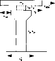
[0010] Figure 1A and 1B are architectural vibration-insulation bearing (Figure 1A) and isolation bridge bearing (Figure 1B) scheme of installation.The building base isolation can be summarized as a purpose, promptly reduces the absolute acceleration of superstructure.Here superstructure refers to be supported on any structure on the shock isolating pedestal.The absolute acceleration that reduces structure is equivalent to reduce the not earthquake of isolation structure input equally.But the isolation bridge system but is a more complicated, and under many circumstances, the acceleration that reduces bridge pier is not the purpose of shock insulation, and topmost purpose is to reduce earthquake input load action down because the seismic forces of the pillar that bridge inertia force causes.Figure 1A and 1B are seen in the difference of building shock insulation and isolation bridge, and the quality definition of superstructure is m
s, damped coefficient and rigidity (spring constant) are designated as c respectively
bAnd k
bIn the structures isolation effect shown in Figure 1A, the absolute acceleration of superstructure is designated as x
Abs", the bearing relative displacement is x
RelConsider the damping and the restoring force of superstructure, the equation that system can be expressed as:
m
sx
abs“+c
bx
rel‘+k
bx
rel=0
But for the isolation bridge shown in Figure 1B, superstructure is supported by pier or post, and pier or post all have the damped coefficient c of itself
pWith spring constant k
pRelative displacement between pier top and the ground is x
pAt this moment, the differential equation of motion of system is
m
sx
abs“+c
bx
rel‘+k
bx
rel+c
px
p‘+k
px
p=0
So the bridge equation has been Duoed two than building shock insulation equation, from the isolation bridge equation as can be seen, reduce absolute acceleration x
Abs" might not directly reduce the displacement x of bearing
Rel, also differ and reduce the displacement x of pier surely
pBut the displacement that reduces bearing and pier is more important than the absolute acceleration that reduces superstructure.
[0011] thereby, the natural period of isolation structure can be regulated by the rigidity that changes bearing, and the displacement of bearing is controlled by the damped coefficient of bearing.The isolation design of building structure is clear and direct.But,, must take into account displacement that reduces bearing and the seismic forces that reduces bridge pier for the shock insulation of bridge construction.In most of the cases, the main purpose of isolation bridge is to reduce the shearing of substrate and the displacement of bearing.So isolation bridge and building shock insulation have very big difference.
[0012] isolation bridge purpose above-mentioned utilizes the particular design of bridge pier to realize usually.Such as, certain pier has the sudden change of rigidity and intensity on the axle of orthogonal (X and Y), enough big such as rigidity and intensity along X-direction, resembles shear wall, so just needn't consider the shock insulation of X-direction, and purpose should be the displacement of restriction X-axis.No. 01/42593 international monopoly shock isolating pedestal of WO has designed identical condition feature simultaneously in X-axis and Y-axis, makes it be difficult to realize the purpose of isolation bridge.
[0013] another problem in No. 01/42593 patent of WO is the stability of bearing in normal load such as wind, traffic etc.Shock isolating pedestal should lock and can not move under normal small load effect, and can play function of shock insulation under geological process.
[0014] shock isolating pedestal in No. 01/42593 patent of WO and above-mentioned some other bearing all do not have fully design reducing the big displacement of bearing, and this key factor of isolation bridge just.The reason that two aspects are arranged of big displacement, a reason is the intrinsic problem of conventional linear (or slightly non-linear) bearing: the motion of the superstructure almost phase place with ground motion is opposite; Another reason is that a lot of susceptor design are not avoided because the big displacement that unstability causes.
[0015] last, another factor that bearing is further optimized in isolation bridge is that isolation bridge is short more a lot of than the cycle of architectural vibration-insulation.
Summary of the invention
[0016] this invention purpose provides a kind of shock isolating pedestal that is specially adapted to isolation bridge.
[0017] another purpose of this invention provides a kind of shock isolating pedestal that automatic recovery ability is arranged under heavy load.
[0018] another purpose of this invention provides a kind of shock isolating pedestal that has effective frictional damping and select to determine friction damping force.
[0019] another purpose of this invention provides a kind of shock isolating pedestal that has lock function under normal non-Horizontal Seismic Load.Consider this purpose of this invention, shock isolating pedestal also has temperature movement relative displacement lock function among a small circle.
[0020] another purpose of this invention provides and a kind ofly has additional damping to reduce support displacement, shortens the shock isolating pedestal in bearing cycle.
[0021] consider these purposes, shock isolating pedestal comprises dull and stereotyped down, and upper flat plate and cylindrical roller are with the upper surface of flat board and the soffit rolling of upper flat plate contact down.Following flat board is fixed in the substrate, and upper flat plate is fixed on the superstructure.Under normal upper load effect, one or two abutment surface are formed slopely centre of the drum, and when relative displacement took place flat board up and down, cylinder was moving partially, and restoring force is provided.A pair of side wall is fixed on down dull and stereotyped going up to keep out the axial direct lateral force of shock insulation, and a pair of rail plate provides dry-friction damping.Locking device comprises many belts, and from the Kong Zhongyu upper flat plate joint of side wall, pin and the combination of stroke seam allow because the generation of the restriction relative displacement that temperature movement causes.Viscoelastic damping or viscous damping, Hookean spring and nonlinear spring are placed in up and down between flat board better as the quenching spring, reduce displacement, dissipation energy, the periodic motion characteristic of regulating bearing.
[0022] shock isolating pedestal is also by providing the shock insulation of X and Y direction at middle the flat board between the flat board up and down, playing bottom roll between flat board and the middle plateform that the shock insulation of directions X is provided, and cylinder provides the shock insulation of Y direction between upper flat plate and the middle plateform.This two-layer shock insulation consider to require to provide different restoring forces and different friction damping forces on X and Y direction according to design.
[0023] but this invention provides also can adopt one deck design, adopt to be positioned at the pyramid surface circular drum that upper and lower surface forms, by the distortion and the rolling friction consumed energy of original shape cylinder.
The objective of the invention is to realize according to following scheme:
A kind of shock isolating pedestal of the support superstructure with respect to the basis comprises:
An axis;
Be fit to the lower wall link to each other with the basis, have up a supporting surface;
Coil on being fit to engage, have down a supporting surface with superstructure;
The a pair of side wall that is installed on lower wall limits the opposed metope of pair of parallel in bearing axis;
One cylindrical shape roller bearing is arranged between the upper and lower dish supporting surface, and its end face contacts with opposed metope respectively;
Up and supporting surface down be set to the reasonable reference position that roller bearing being partial under gravity load provided;
The slideway of roller bearing both ends of the surface is connected on the opposed metope separately, and the frictional force opposite with side wall member direction of relative movement with roller bearing can be provided.
Above-mentioned shock isolating pedestal supporting surface up has a V-shaped substantially section.
The described side wall of above-mentioned shock isolating pedestal can be resisted the lateral load that is equal to or greater than Vertical Load that bearing bears.
Above-mentioned shock isolating pedestal, each side wall member comprises an interchangeable friction extensible guide, to limit two opposed metopes, the friction factor of slideway and metope is selected by suitable friction extensible guide is installed.
Above-mentioned shock isolating pedestal, each slideway comprise an interchangeable stickup frictional disk, and the friction factor of slideway and metope is selected by suitable friction extensible guide is installed.
Above-mentioned shock isolating pedestal, having one in this offside wall member at least can be installed on lower wall by dissoluble mode, and frictional force is alleviated.
Above-mentioned shock isolating pedestal also comprises a check mechanism, go up when preventing to be subjected to horizontal loading in advance dish with respect to lower wall moving along axis direction.
Above-mentioned shock isolating pedestal, check mechanism allow the preceding dish of going up of braking with respect to lower wall one moving along axis to be arranged in limited range.
Above-mentioned shock isolating pedestal, check mechanism comprises:
Be installed on first member of dish, have a screw that connects;
Be installed on second member of lower wall, have mobile notch with the almost overlapping elongation of above-mentioned screw;
Run through the braking nail of above-mentioned screw and mobile notch.
Above-mentioned shock isolating pedestal, the braking nail comprises a pair of nut and nut.
Above-mentioned shock isolating pedestal, that offside wall member has a screwed hole that runs through at least, and check mechanism comprises that one runs through the screw of screwed hole, and it is connected in dish so that adjustable friction brake force to be provided.
Above-mentioned shock isolating pedestal also comprises a Hookean spring, and its two ends are connected in respectively goes up dish and lower wall.
Above-mentioned shock isolating pedestal, above-mentioned wire spring comprises the device that can adjust spring constant.
Above-mentioned shock isolating pedestal also comprises a nonlinear spring, and its two ends are connected in respectively goes up dish and lower wall.
Above-mentioned shock isolating pedestal, nonlinear spring is exactly a hardening spring here.
Above-mentioned shock isolating pedestal, hardening spring comprise an initial blind area, and it does not produce elastic force when last dish has displacement with respect to lower wall, also has one second blind area behind the initial blind area, and the elastic force that its produces is along with the displacement of last dish with respect to lower wall increases and increase.
A kind of shock isolating pedestal of the support superstructure with respect to the basis comprises:
Mutually perpendicular X, Y-axis;
Be fit to the lower wall link to each other with the basis, have up a supporting surface;
Have up and the mid-game of supporting surface down;
Coil on being fit to engage, have down a supporting surface with above-mentioned superstructure;
The a pair of side wall member of being satisfied with lower wall is with the restriction two opposed metopes parallel with X-axis;
The a pair of side wall member of being satisfied with to go up dish is with the restriction two opposed metopes parallel with Y-axis;
In, between the supporting surface of lower wall a bottom cylinder roller bearing is arranged, its both ends of the surface contact with the opposed metope of lower side wall member restriction respectively.
Between the supporting surface of last, mid-game a top cylinder roller bearing is arranged, its both ends of the surface contact with the opposed metope of upper side wall member restriction respectively;
In above-mentioned, the lower wall supporting surface is arranged to provide the suitable reference position along X-axis, the skew to its direction can take place in lower roller under gravity load;
Above-mentioned last, mid-game supporting surface are arranged to provide the suitable reference position along Y-axis, and the skew to its direction can take place under gravity load upper roller.
Above-mentioned shock isolating pedestal also comprises:
Two end faces with the contacted lower cylindrical roller bearing of opposed metope of bottom side wall restriction respectively has a slideway respectively, can provide with lower roller with respect to the opposite frictional force of lower side wall member displacement;
Two end faces with the contacted top cylinder shape of the opposed metope roller bearing of top side wall restriction respectively has a slideway respectively, can provide with upper roller with respect to the opposite frictional force of upper side wall member displacement.
Above-mentioned shock isolating pedestal, mid-game supporting surface down has a section that becomes inverted V-shaped substantially, and its supporting surface up has the section of forming V-shape substantially.
Above-mentioned shock isolating pedestal, each lower side wall member comprises an interchangeable friction extensible guide limiting two opposed metopes, the slideway that links to each other with lower roller and can be selected by suitable friction extensible guide is installed by the friction factor between the metope of lower side wall member restriction.
Above-mentioned shock isolating pedestal, each upper side wall member comprise an interchangeable friction extensible guide limiting opposed metope, the slideway that links to each other with upper roller and can be selected by suitable friction extensible guide is installed by the friction factor between the metope of upper side wall member restriction.
Above-mentioned shock isolating pedestal, each slideway that links to each other with lower cylinder comprises an interchangeable frictional disk, the friction factor between the metope of slideway that links to each other with lower roller and the restriction of lower side wall member can be selected by suitable friction extensible guide is installed.
Above-mentioned shock isolating pedestal, each slideway that links to each other with upper cylinder comprises an interchangeable frictional disk, the slideway that links to each other with upper roller and can be selected by suitable friction extensible guide is installed by the friction factor between the metope of upper side wall member restriction.
Frictional force on the slideway that the upper cylinder that is different from above-mentioned shock isolating pedestal, the frictional force on the slideway of lower cylinder supporting supports.
Above-mentioned shock isolating pedestal, a check mechanism can prevent the mid-game campaign with respect to lower wall in X-axis starting point forward position X-axis, can also prevent produce along the load of X-axis before the Y-axis starting point along Y-axis with respect on the mid-game campaign of dish.
Above-mentioned shock isolating pedestal can be removed alone about X, Y-axis in the check mechanism.
Above-mentioned 26 shock isolating pedestal has at least a lower side wall member to comprise a screwed hole that runs through, and check mechanism comprises that a screw that runs through screwed hole provides adjustable frictional force to connect mid-game.
Above-mentioned shock isolating pedestal has at least a upper side wall member to comprise a screwed hole that runs through, and check mechanism comprises that a screw that runs through screwed hole provides adjustable frictional force to connect mid-game.
Above-mentioned shock isolating pedestal, the cylinder of upper and lower part stand the recovery biasing force of different sizes, with the cylinder on their axial separately reference bit in-migration biasing bottoms and top.
Above-mentioned shock isolating pedestal, mid-game supporting surface down has a section that becomes inverted V-shaped substantially, is symmetrical along its reference position of X-axis, and first inclination angle is arranged; Mid-game supporting surface up has the section of a forming V-shape, is symmetrical along its reference position of Y-axis, and second inclination angle is arranged, and wherein first and second inclination angles varies in size.
Above-mentioned shock isolating pedestal also comprises:
Have at least an X to be connected in lower wall and last dish to spring, X is arranged in the direction parallel or consistent with X-axis to spring;
Have at least a Y to be connected in lower wall and last dish to spring, Y is arranged in the direction parallel or consistent with Y-axis to spring.
Above-mentioned shock isolating pedestal, have at least an X to spring be a Hookean spring, have at least a Y to spring be a Hookean spring.
Above-mentioned shock isolating pedestal, have at least an X to spring be a hardening spring, have at least a Y to spring be a hardening spring.
A kind of shock isolating pedestal of the support superstructure with respect to the basis comprises:
Mutually perpendicular X, Y-axis;
Be fit to the lower wall link to each other with the basis, have up a supporting surface;
Coil on being fit to engage, have down a supporting surface with above-mentioned superstructure;
Between upper and lower dish supporting surface, a spherical roller is arranged;
Up and down supporting surface is provided under the gravity load roller bearing and can gets back to its reference position along X, Y-axis.
Above-mentioned shock isolating pedestal has one to be pyramid up with in the supporting surface down.
Above-mentioned shock isolating pedestal, spherical roller are deformable elastic balls.
Description of drawings
[0024] this essence of an invention and implementation will be described below in more detail, and the explanation of correlation diagram has:
Figure 1A is the schematic diagram of architectural vibration-insulation system;
Figure 1B is the schematic diagram of isolation bridge system;
Fig. 2 faces fragmentary cross-sectional view, is first kind of form of this invention;
Fig. 3 is the side-looking fragmentary cross-sectional view, with the shock isolating pedestal shown in Fig. 2;
Fig. 4 is the phantom drawing of Fig. 2 and shock isolating pedestal cylinder integration section shown in Figure 3;
Fig. 5 is the integrated phantom of cylinder shown in Figure 4;
Fig. 6 is the sectional view of part 66 positions among Fig. 4;
Fig. 7 is the part vertical view of the integrated sweeper of cylinder shown in Figure 4;
Fig. 8 faces fragmentary cross-sectional view, is second kind of form of this invention;
Fig. 9 is the side-looking phantom of shock isolating pedestal shown in Figure 8;
Figure 10 is the notion lateral view, is the third form of this invention;
Figure 11 is the conceptive plan view shown in Figure 10, and top cover is replaced;
Figure 12 is a kind of locking device schematic diagram of shock isolating pedestal in this invention;
Figure 13 is the 13-13 sectional drawing among Figure 12;
Figure 14 is the another kind of locking device schematic diagram of shock isolating pedestal in this invention;
Figure 15 A is under the effect of numerical value seismic stimulation, the time-histories figure line that traditional shock isolating pedestal produces;
Figure 15 B is similar and figure line Figure 15 A, for this submits the time-history curves of the shock isolating pedestal of invention to.
Specific implementation method
[0025], provided first kind of form of the shock isolating pedestal 10 of this invention among the figure referring to Fig. 2 and 3.Shock isolating pedestal 10 has comprised time flat board 12, joins with pedestal, and upper flat plate 14 links to each other with superstructure, exempts from seismic stimulation with the protection structure, and cylinder 16 is with the upper surface 18 of flat board 12 and soffit 20 rollings of upper flat plate 14 contact down.Following dull and stereotyped 12 and upper flat plate 14 adapt to corresponding substrate and structure, vertical a lot of anchor hole (not illustrating among the figure) arranged, the particular surroundings that response and bearing 10 are laid is joined with cement anchor or other suitable fasteners.Shock isolating pedestal 10 is mainly used in the shock insulation of the isolation bridge system shown in Figure 1A, and following dull and stereotyped 12 link to each other with bridge pier, and upper flat plate 14 links to each other with the bridge cover plate.
[0026] relative displacement of X-direction takes place in shock isolating pedestal 10 design permission upper flat plates 14 and down dull and stereotyped 12, along normal direction among Fig. 2 and the horizontal direction among Fig. 3.But for keeping out the big horizontal lateral load of the Y direction vertical with X-direction, a pair of vertical side wall 22 is fixed on down on dull and stereotyped 12, and is fixing well by bolt.Side wall 22 optimal design and fixing be hundred tons load with lateral load, the especially magnitude of keeping out the vertical load that is equal to, or greater than the superstructure that shock isolating pedestal 10 supports, to guarantee that side wall is in the extreme lateral force of Y under load action.
[0027] according to present invention, relative a pair of interior metope 26 is arranged on the side wall 22, be parallel to the directions X of shock isolating pedestal 10.In Fig. 2, side wall 22 comprises dismountable friction track 28, and interior metope 26 can guarantee that the user controls playing smoothness.The importance of this measure will further be discussed.
[0028] in Fig. 3 as can be seen, the rolling surface 18 that makes progress has the V-arrangement face usually, has two facing surfaces to be formed slopely mutually downwards.The angle of slope on each inclined-plane is very little, with level to become 2 the degree, but this angle is selectable, this depends on the system of shock insulation.Acclivitous surperficial 18 can be rolled by large-sized dull and stereotyped steel and form, perhaps cutting fixedly the wedge steel plate form.The minimum point of V-arrangement face just in time is positioned at dull and stereotyped down centre.
[0029] upper flat plate 14 comprises that than flat board 12 is wide down its size of island is just in time between interior wall 22, upwards over against rolling surface 20, downwards over against rolling surface 18.The island can form around rolling plain plate, also can form by being fixed on the little steel plate at a big steel plate.For simplicity, downward rolling surface 20 is flat in this invention.But as further elaboration, surface 20 might not be flat.
[0030] cylinder 16 is made by steel pipe, and shown in Figure 4 and 5, the turning cylinder and bearing 10 X-directions of cylinder 16 oneself are rectangular, a pair of rail plate 32 and inner wall surface 26 slip joint.Rail plate 32 is installed in the two ends of cylinder 16 by non-axis bar 34 and axis bar 36.More specifically, non-axis bar 34 extends in parallel cylinder 16 front and back with roller shaft, and slip guide block 32 and non-axis bar 34 surround cylinder 16 in conjunction with forming a rectangle frame.
[0031] for guaranteeing that rolling surface 18 upwards is not subjected to the influence of iron filings that a pair of sweeper 60 is installed in the front and back of cylinder, Fig. 6 and 7 is depicted as sweeper.Each sweeper 60 comprises a diagonal brace 62, is fixed on the inner surface of the guide block 32 between cylinder 16 and the corresponding non-axis bar 34 by fixed part 4.Screen 66 has and parallelly with the turning cylinder of cylinder 16 is fixed on the angle brace 62 by 68, and the brush 69 of sweeper is installed on the screen 66, when rolling surface 18 is gone up in the cleaning when X shock insulation axle is replaced of cylinder 16 and slip guide block 32.
[0032] when the vertical uniform load q such as weight of braced structures on bearing 10, cylinder 16 can depart from equilbrium position shown in Figure 3, and is rolled on the bottom line of rolling surface 18 that X-axis forms by the V-arrangement surface.Under seismic loading,, will produce elastic restoring force when upper flat plate 14 departs from down dull and stereotypedly 12 the time.Guide block 32 provides friction damping force along X shock insulation direction of principal axis moving of inner surface 26, adds the deadweight restoring force, and energy can dissipate in the mode of heat energy.As above-mentioned, side wall 22 comprises interchangeable friction extensible guide 28.Same, slip guide block 32 comprises friction plate 70, is installed in external surface.Stop work and replace friction extensible guide 28 or friction plate 70, the friction factor of slip guide block 32 and metope 26 will change, to meet the requirement of concrete installation environment.
[0033] another result of this invention is installed in down side wall 22 on dull and stereotyped 12 by set bolt 24.After the earthquake, if cylinder 16 is sticking and or be absorbed on the side wall, side wall 22 can be from dull and stereotyped 12 removing down, cylinder is not subjected to any restriction except very little rolling friction like this, gets back to its equilbrium position under action of gravity easily.
[0034] is locking shock isolating pedestal 10, prevents because the motion that relative very little horizontal loading (being wind, traffic loading etc.) causes is furnished with a large amount of belt 72 on the screwed hole of side wall 22.As shown in Figure 2, belt 72 provides static friction to prevent upper flat plate 14 and the down dull and stereotyped 12 relative replacements in normal non-seismic force effects lower edge bearing 10 X-directions.Belt 72 is tightened the stiction that can provide very big, and advantageously the size of stiction can be regulated the normal load of expectation by changing belt 72.
[0035] as top described, the purpose of isolation bridge is to reduce support displacement by the unstability of control bearing and vibration phase difference.As characteristics of this invention, be very complicated in conjunction with frictional force and deadweight restoring force, as mentioned above, provide frictional damping by guide block 32.As shown in Figure 3, X-axis provides damping unit 80, one ends to be connected with following dull and stereotyped 12 at least, and the other end is connected with upper flat plate 14.Figure 3 shows that a pair of damping unit is positioned at the two ends of cylinder 16 axis of rolling, but only use a damper.When damper 80 is viscosity or viscoelastic damper, can be understood as damper 80 and be Hookean spring or nonlinear spring.Especially, numerical simulation shows that hard spring has initial dead band and is good to reducing support displacement.Hookean spring has adjustable spring constant, for the vibration characteristics of further controlling shock isolating pedestal 10 provides condition.Viscoplasticity and viscous damper, Hookean spring comprise the Hookean spring that spring constant is adjustable, and nonlinear spring comprises that hard spring all is the assembly that can directly buy.
[0036] shown in Figure 15 A and 15B, the placement property of traditional Den Hartog bearing (based on the theoretical bearing model of one or several single-degree-of-freedom) is shown among Figure 15 A, and corresponding figure line of the present invention is seen Figure 15 B.These figure lines are based on the numerical simulation of seismic interference undersetting response.Simulation utilizes the computer program of MATLAB and SIMULINK exploitation to finish.The frictional force of Figure 15 B bearing is 127 tons, and restoring force is that 4 tons of hard springs have 0.0005 inch dead band.Spring constant is 500 tons/meter.The analysis showed that traditional Den Hartog bearing has 55% damping, the cycle is 3 seconds.The structure acceleration reduces 0.09g, and base shear is 1530Kips.Maximum support displacement is above 3 inches.As a comparison, the shock isolating pedestal maximum displacement of the present invention's proposition is less than 1 inch.So maximum displacement has reduced 3 times.Base shear is 1690Kips, a little more than Den Hartog bearing, but still much smaller than 5420 Kips that do not have isolation measure.
[0037] the another kind of shock isolating pedestal 110 of the present invention's proposition is seen Fig. 8 and 9.Shock isolating pedestal 110 is similar with shock isolating pedestal 10, except shock isolating pedestal 110 provides the X of orthogonal and the shock insulation of Y-axis both direction.Shock isolating pedestal 110 generally includes down flat board 112, is fixed in the substrate, and middle plateform 113 and upper flat plate 114 link to each other with superstructure.Following cylindrical roller 116 contacts with 119 rollings of the soffit of following dull and stereotyped 112 upper surface 118 and middle plateform 113, provides down between flat board and the middle plateform along the axial relative displacement of X shock insulation.Same last cylinder 117 provides between middle plateform and the upper flat plate along the axial relative displacement of Y shock insulation between the soffit 120 of the upper surface 121 of middle plateform 113 and upper flat plate 114.
[0038] for improving the parts interchangeability of making efficient and first kind of form and second kind of form, in second kind of form, the X of middle plateform 113 and Y shock insulation direction of principal axis all are the inclined-plane.So soffit 119 has anti-V-type section, but upper surface 121 has the V-type section.For simplicity dull and stereotyped 112 upper surface 118 and upper flat plate 114 are flat down.Abutment surface so is provided with, offer bottom roll 116 along the axial normal reference position of X shock insulation and last cylinder 11 7 along the axial normal reference position of Y shock insulation, up-down roller all will take place to depart from accordingly under the gravity load effect.
[0039] upright side wall 122 is fixed on down on dull and stereotyped 112, and handstand side wall 123 depends on upper flat plate 114.End cap 129 is two-layer up and down around bearing 110, prevents that chip from entering bearing inside.Bottom roll 116 transports slip guide block 132, and with inner surface 126 sliding-contacts of respective inside wall 122, similarly, last cylinder 117 transports inner surface 127 sliding-contacts of slip guide block 133 and respective inside wall 123.Produce friction damping force simultaneously on X and the Y shock insulation direction of principal axis as a result.
[0040] as implied above, the specific factor of some of structural environment may make shock isolating pedestal show different shock insulation features at X shock insulation axle with Y shock insulation axle.In shock isolating pedestal 110, a kind of approach is to utilize different friction extensible guides to realize different friction factor with friction plates.Another approach is the angle of slope that utilizes soffit 119 and upper surface 121 different, allows shock isolating pedestal 110 provide different from the X restoring force different with the Y direction.This mode provides method for limiting support displacement, and common and angle of slope is inversely proportional to.
[0041] dissimilar dampers (not illustrating among Fig. 8 and 9) can be installed in down between flat board 112 and the middle plateform 113 along X shock insulation axle (parallel or coincidence), also can be installed between middle plateform and the upper flat plate
(be parallel to or consistent) Y-axis, in this respect, the description of damping unit 80 that is used for connecting the shock isolating pedestal 10 of first equipment also has reference.
[0042] Figure 12 and Figure 13 have described a check mechanism, and it all is useful at the shock isolating pedestal 10 of first kind of equipment and the shock isolating pedestal 110 of second kind of equipment, and it is as the alternative of the bolt 72 of above-mentioned connection shock isolating pedestal 10 under latter instance.The Y of shock isolating pedestal 110 to, check mechanism comprises first member 140 that is installed on dish 114 and a screw 142 is arranged, be installed on second member 144 of mid-game 113 and approximately overlapping with screw 142 a mobile notch 146 that is parallel to the y axle is arranged, and the screw 148 by screw 142 and replacement notch 146.Spring shim 152 between the nut 150 of screw 148 ends, nut 150 and first member 140, and another one spring shim 154 actings in conjunction between first member 140 and second member 144, in screw 148, keep axial tension so that a kind of friction brake force to be provided.Can find out better that at Figure 13 screw 148 comprises a special head 156 that elongates, for when its during for level can with replacement notch 146 fits.Head 156 is present in the square indentations of second member 144, and member 144 restriction screws 148 do not make its rotation when applying axial force, and allow fastening nut 150.Tension on member 140 and 144 preferably can not be used corrosion-resistant material because there being possible corrosion.Figure 12 and 13 check mechanism allow the motion in replacement notch scope when apply the static load that is for example caused by heat.Yet when violent earthquake took place, screw 148 had just ruptured to allow bearing by its predetermined way motion.When screw 148 fractures, the coupling part of nut 150 and screw 148 drops to the outside of bearing, drops in the member 144 top containers, in order to avoid bolt portion drops to abutment surface yet the remainder of screw comprises head 156.Screw 148 parts of earthquake rear support the inside are easy to take out from container, and a new screw can be installed.
[0043] Figure 14 has showed another check mechanism, and it all is useful at the shock isolating pedestal 10 of first kind of equipment and the shock isolating pedestal 110 of second kind of equipment, under latter instance as the alternative of the bolt 72 of above-mentioned connection shock isolating pedestal 10.Be similar to aforesaid screw 72, the check mechanism of Figure 14 is a kind of variation of screw 172, however the screw 172 that changes in its length, shrink, become circle in its commissure tips, resemble a deformable semi girder and allow little support displacement.The screw 172 that changes will rupture when earthquake to allow bearing by design work.
[0044] Figure 10 and Figure 11 conceptual displaying invented the corresponding to shock isolating pedestal 210 of the third equipment therewith.Shock isolating pedestal 210 along X, Y to gravity load under restoring force is provided, do not need to resemble the roller bearing of two separation in shock isolating pedestal 110 and two-layer.More particularly, shock isolating pedestal 210 comprises a lower wall 212, be suitable for being connected with ground, and a supporting surface that makes progress 218 arranged, go up dish 214, be suitable for being connected, and a downward supporting surface 220 is arranged for one with superstructure, also have the roller bearing 216 that cardinal principle is spherical in shape, between upper lower burrs and with supporting surface 218, contact with 220.Supporting surface 218 and 220 one of them or two are pyramid to limit four surface locations, and all like this inclined-planes are all towards the reference position of same position with restriction spin 216.See Figure 11, supporting surface 218 up comprises four parts, and 218A, 28B, 218C and 218D incline to a middle point is little.Spin 216 when having relative motion to take place as the viscoelastic damping energy dissipation that provides preferably, to reduce vertical acceleration.When spin 216 is between supporting surface 218 and 220, just be equivalent to dry friction damping.Damping material is preferably with the material that can increase dry friction damping power.Discussed above and first, second device-dependent characteristic comprise different check mechanism and use the damping unit of Hookean spring, hardening spring and installation, are suitable for the third equipment equally.
[0045] this invention effectively protection and separating building and bridge exempt from seismic load and destroy, this is highly significant.Yet this invention is more effective at the shock insulation of protection interior of building " subsystem ".The example of subsystem resembles computer and data-storage system, vulnerable equipment, sculpture and other art work etc.When earthquake attacked, building structure may be amplified acceleration and displacement, yet be not allowed to often in the excessive displacement of building interior subsystem.Therefore in this case, absolute acceleration and support displacement need to reduce, and what compare is isolation bridge, and the minimizing of its absolute acceleration is out of question, and the bottom shearing of bridge harbour and bridge pier does not need to consider.Its bottom shearing often can be ignored in the shock insulation problem of subsystem, and purpose is for absolute acceleration that reduces superstructure and support displacement.
Claims (33)
1, a kind of shock isolating pedestal of the support superstructure with respect to the basis is characterized in that comprising:
An axis;
Be fit to the lower wall link to each other with the basis, have up a supporting surface;
Coil on being fit to engage, have down a supporting surface with superstructure;
The a pair of side wall that is installed on lower wall limits the opposed metope of pair of parallel in bearing axis;
One cylindrical shape roller bearing is arranged between the upper and lower dish supporting surface, and its end face contacts with opposed metope respectively;
Up and supporting surface down be set to the reasonable reference position that roller bearing being partial under gravity load provided;
The slideway of roller bearing both ends of the surface is connected on the opposed metope separately, and the frictional force opposite with side wall member direction of relative movement with roller bearing can be provided.
2,, it is characterized in that supporting surface up has a V-shaped substantially section according to the described shock isolating pedestal of claim 1.
3,, it is characterized in that described side wall can resist the lateral load that is equal to or greater than Vertical Load that bearing bears according to the described shock isolating pedestal of claim 1.
4, according to the described shock isolating pedestal of claim 1, it is characterized in that each side wall member comprises an interchangeable friction extensible guide, to limit two opposed metopes, the friction factor of slideway and metope is selected by suitable friction extensible guide is installed.
5, according to the described shock isolating pedestal of claim 1, it is characterized in that each slideway comprises an interchangeable stickup frictional disk, the friction factor of slideway and metope is selected by suitable friction extensible guide is installed.
6,, it is characterized in that having one in this offside wall member at least can be installed on lower wall by dissoluble mode, makes frictional force alleviate like this according to the described shock isolating pedestal of claim 1.
7, according to the described shock isolating pedestal of claim 1, it is characterized in that also comprising a check mechanism, go up when preventing to be subjected to horizontal loading in advance dish with respect to lower wall moving along axis direction.
8,, it is characterized in that check mechanism allows the preceding dish of going up of braking with respect to lower wall one moving along axis to be arranged in limited range according to the described shock isolating pedestal of claim 7.
9,, it is characterized in that check mechanism comprises according to the described shock isolating pedestal of claim 7:
Be installed on first member of dish, have a screw that connects;
Be installed on second member of lower wall, have mobile notch with the almost overlapping elongation of above-mentioned screw;
Run through the braking nail of above-mentioned screw and mobile notch.
10,, it is characterized in that the braking nail comprises a pair of nut and nut according to the described shock isolating pedestal of claim 9.
11, according to the described shock isolating pedestal of claim 7, it is characterized in that that above-mentioned offside wall member has a screwed hole that runs through at least, check mechanism comprises that one runs through the screw of screwed hole, it is connected in dish so that adjustable friction brake force to be provided.
12, according to the described shock isolating pedestal of claim 1, it is characterized in that also comprising a Hookean spring, its two ends are connected in respectively goes up dish and lower wall.
13,, it is characterized in that above-mentioned wire spring comprises the device that can adjust spring constant according to the described shock isolating pedestal of claim 12.
14, according to the described shock isolating pedestal of claim 1, it is characterized in that also comprising a nonlinear spring, its two ends are connected in respectively goes up dish and lower wall.
15,, it is characterized in that nonlinear spring is exactly a hardening spring according to the described shock isolating pedestal of claim 14.
16, according to the described shock isolating pedestal of claim 15, it is characterized in that hardening spring comprises an initial blind area, it does not produce elastic force when last dish has displacement with respect to lower wall, also has one second blind area behind the initial blind area, and the elastic force that its produces is along with the displacement of last dish with respect to lower wall increases and increase.
17, a kind of shock isolating pedestal of the support superstructure with respect to the basis is characterized in that comprising:
Mutually perpendicular X, Y-axis;
Be fit to the lower wall link to each other with the basis, have up a supporting surface;
Have up and the mid-game of supporting surface down;
Coil on being fit to engage, have down a supporting surface with above-mentioned superstructure;
The a pair of side wall member of being satisfied with lower wall is with the restriction two opposed metopes parallel with X-axis;
The a pair of side wall member of being satisfied with to go up dish is with the restriction two opposed metopes parallel with Y-axis;
In, between the supporting surface of lower wall a bottom cylinder roller bearing is arranged, its both ends of the surface contact with the opposed metope of lower side wall member restriction respectively;
Between the supporting surface of last, mid-game a top cylinder roller bearing is arranged, its both ends of the surface contact with the opposed metope of upper side wall member restriction respectively;
In above-mentioned, the lower wall supporting surface is arranged to provide the suitable reference position along X-axis, the skew to its direction can take place in lower roller under gravity load;
Above-mentioned last, mid-game supporting surface are arranged to provide the suitable reference position along Y-axis, and the skew to its direction can take place under gravity load upper roller.
18, according to the described shock isolating pedestal of claim 17, it is characterized in that also comprising:
Two end faces with the contacted lower cylindrical roller bearing of opposed metope of bottom side wall restriction respectively has a slideway respectively, can provide with lower roller with respect to the opposite frictional force of lower side wall member displacement;
Two end faces with the contacted top cylinder shape of the opposed metope roller bearing of top side wall restriction respectively has a slideway respectively, can provide with upper roller with respect to the opposite frictional force of upper side wall member displacement.
19,, it is characterized in that mid-game supporting surface down has a section that becomes inverted V-shaped substantially, and its supporting surface up there is the section of forming V-shape substantially according to the described shock isolating pedestal of claim 18.
20, according to the described shock isolating pedestal of claim 18, it is characterized in that each lower side wall member comprises an interchangeable friction extensible guide limiting two opposed metopes, the slideway that links to each other with lower roller and can select by suitable friction extensible guide is installed by the friction factor between the metope of lower side wall member restriction.
21, according to the described shock isolating pedestal of claim 18, it is characterized in that each upper side wall member comprises an interchangeable friction extensible guide limiting opposed metope, the slideway that links to each other with upper roller and can select by suitable friction extensible guide is installed by the friction factor between the metope of upper side wall member restriction.
22, according to the described shock isolating pedestal of claim 18, it is characterized in that each slideway that links to each other with lower cylinder comprises an interchangeable frictional disk, the friction factor between the metope of slideway that links to each other with lower roller and the restriction of lower side wall member can be selected by suitable friction extensible guide is installed.
23, according to the described shock isolating pedestal of claim 18, it is characterized in that each slideway that links to each other with upper cylinder comprises an interchangeable frictional disk, the slideway that links to each other with upper roller and can select by suitable friction extensible guide is installed by the friction factor between the metope of upper side wall member restriction.
24,, it is characterized in that frictional force on the slideway of lower cylinder supporting is different from the frictional force on the slideway of upper cylinder supporting according to the described shock isolating pedestal of claim 18.
25, according to the described shock isolating pedestal of claim 18, it is characterized in that a check mechanism, can prevent mid-game campaign with respect to lower wall in X-axis starting point forward position X-axis, can also prevent produce along the load of X-axis before the Y-axis starting point along Y-axis with respect on the mid-game campaign of dish.
26,, it is characterized in that to remove alone about X, Y-axis in the check mechanism according to the described shock isolating pedestal of claim 25.
27, according to the described shock isolating pedestal of claim 26, it is characterized in that having at least a lower side wall member to comprise a screwed hole that runs through, check mechanism comprises that a screw that runs through screwed hole provides adjustable frictional force to connect mid-game.
28, according to the described shock isolating pedestal of claim 26, it is characterized in that having at least a upper side wall member to comprise a screwed hole that runs through, check mechanism comprises that a screw that runs through screwed hole provides adjustable frictional force to connect mid-game.
29,, it is characterized in that the cylinder of upper and lower part stands the recovery biasing force of different sizes, with the cylinder on their axial separately reference bit in-migration biasing bottoms and top according to the described shock isolating pedestal of claim 17.
30,, it is characterized in that mid-game supporting surface down has a section that becomes inverted V-shaped substantially, is symmetrical along its reference position of X-axis, and first inclination angle is arranged according to the described shock isolating pedestal of claim 29; Mid-game supporting surface up has the section of a forming V-shape, is symmetrical along its reference position of Y-axis, and second inclination angle is arranged, and wherein first and second inclination angles varies in size.
31, according to the described shock isolating pedestal of claim 17, it is characterized in that also comprising:
Have at least an X to be connected in lower wall and last dish to spring, X is arranged in the direction parallel or consistent with X-axis to spring;
Have at least a Y to be connected in lower wall and last dish to spring, Y is arranged in the direction parallel or consistent with Y-axis to spring.
32, according to the described shock isolating pedestal of claim 31, it is characterized in that having at least an X to spring be a Hookean spring, have at least a Y to spring be a Hookean spring.
33, according to the described shock isolating pedestal of claim 31, it is characterized in that having at least an X to spring be a hardening spring, have at least a Y to spring be a hardening spring.
Applications Claiming Priority (2)
| Application Number | Priority Date | Filing Date | Title |
|---|---|---|---|
| US09/994,148 US20030099413A1 (en) | 2001-11-26 | 2001-11-26 | Seismic isolation bearing |
| US09/994,148 | 2001-11-26 |
Publications (2)
| Publication Number | Publication Date |
|---|---|
| CN1421582A CN1421582A (en) | 2003-06-04 |
| CN1173101C true CN1173101C (en) | 2004-10-27 |
Family
ID=25540328
Family Applications (1)
| Application Number | Title | Priority Date | Filing Date |
|---|---|---|---|
| CNB021526265A Expired - Fee Related CN1173101C (en) | 2001-11-26 | 2002-11-26 | Shock isolation support |
Country Status (4)
| Country | Link |
|---|---|
| US (1) | US20030099413A1 (en) |
| JP (1) | JP2003232400A (en) |
| CN (1) | CN1173101C (en) |
| TW (1) | TW591167B (en) |
Cited By (6)
| Publication number | Priority date | Publication date | Assignee | Title |
|---|---|---|---|---|
| CN100420873C (en) * | 2005-04-05 | 2008-09-24 | 蔡崇兴 | Vibration isolator |
| US8780808B2 (en) | 1999-02-02 | 2014-07-15 | Isco International, Llc | Method and device for maintaining the performance quality of a communication system in the presence of narrow band interference |
| US9209857B2 (en) | 2013-03-15 | 2015-12-08 | Isco International, Llc | Method and apparatus for signal interference processing |
| US9231650B2 (en) | 2008-11-11 | 2016-01-05 | Isco International, Llc | Method and apparatus for an adaptive filter architecture |
| CN108532450A (en) * | 2018-04-25 | 2018-09-14 | 云南武易高速公路建设指挥部 | A kind of continuous bridge preloaded spring temporary consolidation device |
| US11855670B2 (en) | 2017-04-05 | 2023-12-26 | Isco International, Llc | Method and apparatus for real-time monitoring and field adjustment |
Families Citing this family (41)
| Publication number | Priority date | Publication date | Assignee | Title |
|---|---|---|---|---|
| KR100880995B1 (en) | 2007-01-25 | 2009-02-03 | 후지쯔 가부시끼가이샤 | Audio encoding apparatus and audio encoding method |
| JP5715248B2 (en) | 2010-06-30 | 2015-05-07 | エクソンモービル アップストリーム リサーチ カンパニー | Compliant deck tower |
| CN101962934B (en) * | 2010-09-28 | 2012-09-05 | 成都市新筑路桥机械股份有限公司 | One-way movable damper for bridge |
| CN102433933B (en) * | 2011-10-12 | 2014-01-22 | 北京工业大学 | Anti-pulling type horizontal roller support |
| US8857110B2 (en) * | 2011-11-11 | 2014-10-14 | The Research Foundation For The State University Of New York | Negative stiffness device and method |
| US20130145703A1 (en) * | 2011-12-12 | 2013-06-13 | Yutaka Tomoyasu | Seismological Engineering |
| CN103225663B (en) * | 2012-01-31 | 2016-04-13 | 3M创新有限公司 | Vibration control equipment |
| CN102953329A (en) * | 2012-11-27 | 2013-03-06 | 柳州东方工程橡胶制品有限公司 | Bridge viscous damping shock-absorption supporting seat |
| JP5746789B2 (en) * | 2013-06-20 | 2015-07-08 | 日立機材株式会社 | Base-isolated floor structure |
| US9206616B2 (en) | 2013-06-28 | 2015-12-08 | The Research Foundation For The State University Of New York | Negative stiffness device and method |
| CN103669578B (en) * | 2013-12-12 | 2017-09-29 | 海南大学 | Rotate shock isolating pedestal |
| JP6195534B2 (en) * | 2014-03-28 | 2017-09-13 | 公益財団法人鉄道総合技術研究所 | Bearing type pin support and reinforcement method |
| CN105276055B (en) * | 2014-07-15 | 2017-12-08 | 冠研(上海)专利技术有限公司 | Board with shockproof runners |
| CN104790437B (en) * | 2015-04-20 | 2017-05-03 | 华北水利水电大学 | Base isolating device |
| CN104874132A (en) * | 2015-05-15 | 2015-09-02 | 华侨大学 | Multi-functional earthquake emergency response escape slide for public building |
| CN105201075B (en) * | 2015-09-14 | 2017-05-10 | 北京市建筑设计研究院有限公司 | Split type unidirectional sliding hinge support seat |
| CN105332420B (en) * | 2015-11-29 | 2017-09-29 | 北京工业大学 | A kind of releasable single direction displacement and its roller support and the practice of corner |
| CN105804261B (en) * | 2016-03-21 | 2017-12-26 | 同济大学 | Suspension type material damping device |
| CN106149547A (en) * | 2016-07-07 | 2016-11-23 | 山东省环能设计院股份有限公司 | A kind of steel truss roller support |
| CN108755396B (en) * | 2017-04-26 | 2019-10-22 | 杭州天时亿科技有限公司 | A kind of buffer limit component for the highway bridge benzvalene form cushioning support-saddle that damping property is high |
| CN107059604B (en) * | 2017-05-13 | 2019-03-01 | 南京东交加固工程有限公司 | A kind of adjustable bridge pad |
| RU176418U1 (en) * | 2017-07-21 | 2018-01-18 | Загид Гаджиевич Хучбаров | SUPPORT PART OF THE BEAM BRIDGE |
| CN107574946B (en) * | 2017-10-10 | 2023-12-29 | 广州大学 | Bidirectional large-displacement variable-damping metal damping device |
| CN110145045B (en) * | 2017-10-21 | 2020-08-28 | 山东建筑大学 | Limiting energy dissipation structure and construction method thereof |
| CN107927031B (en) * | 2017-11-27 | 2020-01-07 | 达利食品集团有限公司 | A support frock for flour-mixing machine |
| RU179029U1 (en) * | 2018-01-31 | 2018-04-25 | Загид Гаджиевич Хучбаров | BRIDGE SUPPORT |
| CN108222279B (en) * | 2018-02-06 | 2019-10-01 | 华北水利水电大学 | A kind of novel base for supporting isolation structure and its installation method |
| CN108331192B (en) * | 2018-02-12 | 2020-04-28 | 孙韬 | Shock insulation support assembly and building |
| TWI706095B (en) * | 2018-08-23 | 2020-10-01 | 財團法人國家實驗研究院 | Geometrically nonlinear isolation system |
| CN109505235A (en) * | 2018-12-03 | 2019-03-22 | 中铁大桥局武汉桥梁特种技术有限公司 | A kind of bridge pad |
| CN110084478A (en) * | 2019-03-28 | 2019-08-02 | 宁波工程学院 | A kind of limiting load standard evaluation method of existing concrete bridges |
| CN112145618A (en) * | 2019-06-28 | 2020-12-29 | 南京唐壹信息科技有限公司 | Mechanism for preventing seed grader from violently shaking |
| CN111396498B (en) * | 2019-12-06 | 2021-08-17 | 浙江运达风电股份有限公司 | Nonlinear vibration damper for wind turbine tower |
| CN111101615A (en) * | 2019-12-30 | 2020-05-05 | 潘伯祥 | Damping device for building |
| US11193294B2 (en) * | 2020-04-06 | 2021-12-07 | National Cheng-Kung University | Double variable sliding isolator |
| CN112252504B (en) * | 2020-09-04 | 2022-03-25 | 同济大学 | Compound friction pendulum isolation bearing based on cylinder principle |
| CN112302186A (en) * | 2020-09-16 | 2021-02-02 | 北京工业大学 | Circular arc groove roller friction support for support column of underground subway station |
| CN113756445B (en) * | 2021-09-17 | 2022-07-12 | 上海大学 | Prefabricated assembled shock insulation support |
| CN114000602B (en) * | 2021-10-25 | 2022-08-23 | 北京交通大学 | Initial rigidity adjustable assembled composite damping self-resetting support |
| CN115163741B (en) * | 2022-07-28 | 2024-03-01 | 安徽工程大学 | Electric automobile drive axle controller with shock-absorbing function |
| CN117145926B (en) * | 2023-10-30 | 2024-04-09 | 南通康而健环保科技有限公司 | Shock absorber for environment-friendly mechanical installation based on sewage treatment |
Family Cites Families (3)
| Publication number | Priority date | Publication date | Assignee | Title |
|---|---|---|---|---|
| DE3941778C1 (en) * | 1989-12-18 | 1991-02-21 | New-York Hamburger Gummi-Waaren Co Ag, 2100 Hamburg, De | |
| US5599106A (en) * | 1994-02-09 | 1997-02-04 | Tekton | Ball-in-cone seismic isolation bearing |
| TR200000330T2 (en) * | 1997-08-08 | 2000-05-22 | Robinson Seismic Limited | Energy absorber |
-
2001
- 2001-11-26 US US09/994,148 patent/US20030099413A1/en not_active Abandoned
-
2002
- 2002-10-24 TW TW091124750A patent/TW591167B/en not_active IP Right Cessation
- 2002-11-25 JP JP2002341370A patent/JP2003232400A/en active Pending
- 2002-11-26 CN CNB021526265A patent/CN1173101C/en not_active Expired - Fee Related
Cited By (35)
| Publication number | Priority date | Publication date | Assignee | Title |
|---|---|---|---|---|
| US9198055B2 (en) | 1999-02-02 | 2015-11-24 | Isco International, Llc | Method and device for maintaining the performance quality of a communication system in the presence of narrow band interference |
| US8948328B2 (en) | 1999-02-02 | 2015-02-03 | Isco International, Llc | Method and device for maintaining the performance quality of a communication system in the presence of narrow band interference |
| US8873464B2 (en) | 1999-02-02 | 2014-10-28 | Isco International, Llc | Method and device for maintaining the performance quality of a communication system in the presence of narrow band interference |
| US9451495B2 (en) | 1999-02-02 | 2016-09-20 | Isco International, Llc | Method and device for maintaining the performance quality of a communication system in the presence of narrow band interference |
| US8948141B2 (en) | 1999-02-02 | 2015-02-03 | Isco International, Llc | Method and device for maintaining the performance quality of a communication system in the presence of narrow band interference |
| US9215723B2 (en) | 1999-02-02 | 2015-12-15 | Isco International, Llc | Method and device for maintaining the performance quality of a communication system in the presence of narrow band interference |
| US8976700B2 (en) | 1999-02-02 | 2015-03-10 | Isco International, Llc | Method and device for maintaining the performance quality of a communication system in the presence of narrow band interference |
| US9014100B2 (en) | 1999-02-02 | 2015-04-21 | Isco International, Llc | Method and device for maintaining the performance quality of a communication system in the presence of narrow band interference |
| US9025571B2 (en) | 1999-02-02 | 2015-05-05 | Isco International, Llc | Method and device for maintaining the performance quality of a communication system in the presence of narrow band interference |
| US9026057B2 (en) | 1999-02-02 | 2015-05-05 | Isco International, Llc | Method and device for maintaining the performance quality of a communication system in the presence of narrow band interference |
| US9031509B2 (en) | 1999-02-02 | 2015-05-12 | Isco International, Llc | Method and device for maintaining the performance quality of a communication system in the presence of narrow band interference |
| US9100850B2 (en) | 1999-02-02 | 2015-08-04 | Isco International, Llc | Method and device for maintaining the performance quality of a communication system in the presence of narrow band interference |
| US9100859B2 (en) | 1999-02-02 | 2015-08-04 | Isco International, Llc | Method and device for maintaining the performance quality of a communication system in the presence of narrow band interference |
| US9100867B2 (en) | 1999-02-02 | 2015-08-04 | Isco International, Llc | Method and device for maintaining the performance quality of a communication system in the presence of narrow band interference |
| US9100860B2 (en) | 1999-02-02 | 2015-08-04 | Isco International, Llc | Method and device for maintaining the performance quality of a communication system in the presence of narrow band interference |
| US9107224B2 (en) | 1999-02-02 | 2015-08-11 | Isco International, Llc | Method and device for maintaining the performance quality of a communication system in the presence of narrow band interference |
| US9247553B2 (en) | 1999-02-02 | 2016-01-26 | Isco International, Llc | Method and device for maintaining the performance quality of a communication system in the presence of narrow band interference |
| US8780808B2 (en) | 1999-02-02 | 2014-07-15 | Isco International, Llc | Method and device for maintaining the performance quality of a communication system in the presence of narrow band interference |
| US8971207B2 (en) | 1999-02-02 | 2015-03-03 | Isco International, Llc | Method and device for maintaining the performance quality of a communication system in the presence of narrow band interference |
| US9215719B2 (en) | 1999-02-02 | 2015-12-15 | Isco International, Llc | Method and device for maintaining the performance quality of a communication system in the presence of narrow band interference |
| US9232423B2 (en) | 1999-02-02 | 2016-01-05 | Isco International, Llc | Method and device for maintaining the performance quality of a communication system in the presence of narrow band interference |
| CN100420873C (en) * | 2005-04-05 | 2008-09-24 | 蔡崇兴 | Vibration isolator |
| US9281864B2 (en) | 2008-11-11 | 2016-03-08 | Isco International, Llc | Method and apparatus for an adaptive filter architecture |
| US9294144B2 (en) | 2008-11-11 | 2016-03-22 | Isco International, Llc | Method and apparatus for an adaptive filter architecture |
| US9231650B2 (en) | 2008-11-11 | 2016-01-05 | Isco International, Llc | Method and apparatus for an adaptive filter architecture |
| US9319916B2 (en) | 2013-03-15 | 2016-04-19 | Isco International, Llc | Method and appartus for signal interference processing |
| US9271185B2 (en) | 2013-03-15 | 2016-02-23 | Isco International, Llc | Method and apparatus for interference mitigation utilizing antenna pattern adjustments |
| US9313680B2 (en) | 2013-03-15 | 2016-04-12 | Isco International, Llc | Method and apparatus for signal interference processing |
| US9357426B2 (en) | 2013-03-15 | 2016-05-31 | Isco International, Llc | Method and apparatus for avoiding interference |
| US9369909B2 (en) | 2013-03-15 | 2016-06-14 | Isco International, Llc | Method and apparatus for mitigating signal interference in a feedback system |
| US9426692B2 (en) | 2013-03-15 | 2016-08-23 | Isco International, Llc | Creating library of interferers |
| US9209857B2 (en) | 2013-03-15 | 2015-12-08 | Isco International, Llc | Method and apparatus for signal interference processing |
| US9214983B2 (en) | 2013-03-15 | 2015-12-15 | Isco International, Llc | Method and apparatus for collecting and processing interference information |
| US11855670B2 (en) | 2017-04-05 | 2023-12-26 | Isco International, Llc | Method and apparatus for real-time monitoring and field adjustment |
| CN108532450A (en) * | 2018-04-25 | 2018-09-14 | 云南武易高速公路建设指挥部 | A kind of continuous bridge preloaded spring temporary consolidation device |
Also Published As
| Publication number | Publication date |
|---|---|
| TW591167B (en) | 2004-06-11 |
| JP2003232400A (en) | 2003-08-22 |
| US20030099413A1 (en) | 2003-05-29 |
| CN1421582A (en) | 2003-06-04 |
Similar Documents
| Publication | Publication Date | Title |
|---|---|---|
| CN1173101C (en) | Shock isolation support | |
| CN1222666C (en) | Viaduct bridge substructure and its design method | |
| US6971795B2 (en) | Seismic isolation bearing | |
| CN1084861C (en) | Energy absorber | |
| CN1281525A (en) | Method and apparatus to control seismic forces accelerations, and displacement of structures | |
| KR100686392B1 (en) | Bridge support | |
| CN1265723A (en) | Energy absorber | |
| JP2009541626A (en) | Stable flooring against earthquakes | |
| CN1939834A (en) | Device for hanging a rail, especially a transporting rail of a conveyor or a hoist | |
| CN107906261B (en) | Concrete pump pipe shock-absorbing supporting device | |
| CN211341853U (en) | Building engineering safety device | |
| JP3898509B2 (en) | Function change repair method for existing elastic bearings | |
| CN200978383Y (en) | Height adjustable bridge bearing | |
| CN214656283U (en) | Anti-seismic device for highway bridge | |
| JP2003206509A (en) | Function change repair construction method for existing elastic support | |
| CN111749108B (en) | Vibration device for resonance crusher | |
| CN1117225C (en) | Vibration eliminating device | |
| KR200392800Y1 (en) | Floor frame system | |
| JP2006029593A (en) | Vibration eliminating device | |
| JP2007278340A (en) | Method for installing damper for seismically isolated structure and damping structure | |
| KR200396549Y1 (en) | Foundation Structure of construction | |
| CN214301229U (en) | Bridge pier fixing device | |
| JP4911823B2 (en) | Anchor frame anchoring structure | |
| CN217517349U (en) | Self-adaptive fast-assembling shock absorption and isolation support for highway bridge | |
| CN220203594U (en) | Buffer guard rail for highway construction |
Legal Events
| Date | Code | Title | Description |
|---|---|---|---|
| C06 | Publication | ||
| PB01 | Publication | ||
| C10 | Entry into substantive examination | ||
| SE01 | Entry into force of request for substantive examination | ||
| C14 | Grant of patent or utility model | ||
| GR01 | Patent grant | ||
| C17 | Cessation of patent right | ||
| CF01 | Termination of patent right due to non-payment of annual fee |
Granted publication date: 20041027 Termination date: 20111126 |