CN1171100C - Optical film with variable angle prisms - Google Patents
Optical film with variable angle prisms Download PDFInfo
- Publication number
- CN1171100C CN1171100C CNB008139695A CN00813969A CN1171100C CN 1171100 C CN1171100 C CN 1171100C CN B008139695 A CNB008139695 A CN B008139695A CN 00813969 A CN00813969 A CN 00813969A CN 1171100 C CN1171100 C CN 1171100C
- Authority
- CN
- China
- Prior art keywords
- prism
- light
- prisms
- angle
- optical inversion
- Prior art date
- Legal status (The legal status is an assumption and is not a legal conclusion. Google has not performed a legal analysis and makes no representation as to the accuracy of the status listed.)
- Expired - Fee Related
Links
Images


Classifications
-
- G—PHYSICS
- G02—OPTICS
- G02B—OPTICAL ELEMENTS, SYSTEMS OR APPARATUS
- G02B5/00—Optical elements other than lenses
- G02B5/04—Prisms
-
- G—PHYSICS
- G02—OPTICS
- G02B—OPTICAL ELEMENTS, SYSTEMS OR APPARATUS
- G02B6/00—Light guides; Structural details of arrangements comprising light guides and other optical elements, e.g. couplings
- G02B6/0001—Light guides; Structural details of arrangements comprising light guides and other optical elements, e.g. couplings specially adapted for lighting devices or systems
- G02B6/0011—Light guides; Structural details of arrangements comprising light guides and other optical elements, e.g. couplings specially adapted for lighting devices or systems the light guides being planar or of plate-like form
- G02B6/0033—Means for improving the coupling-out of light from the light guide
- G02B6/005—Means for improving the coupling-out of light from the light guide provided by one optical element, or plurality thereof, placed on the light output side of the light guide
- G02B6/0053—Prismatic sheet or layer; Brightness enhancement element, sheet or layer
-
- G—PHYSICS
- G02—OPTICS
- G02B—OPTICAL ELEMENTS, SYSTEMS OR APPARATUS
- G02B6/00—Light guides; Structural details of arrangements comprising light guides and other optical elements, e.g. couplings
- G02B6/0001—Light guides; Structural details of arrangements comprising light guides and other optical elements, e.g. couplings specially adapted for lighting devices or systems
- G02B6/0011—Light guides; Structural details of arrangements comprising light guides and other optical elements, e.g. couplings specially adapted for lighting devices or systems the light guides being planar or of plate-like form
- G02B6/0013—Means for improving the coupling-in of light from the light source into the light guide
- G02B6/0023—Means for improving the coupling-in of light from the light source into the light guide provided by one optical element, or plurality thereof, placed between the light guide and the light source, or around the light source
- G02B6/0031—Reflecting element, sheet or layer
-
- G—PHYSICS
- G02—OPTICS
- G02B—OPTICAL ELEMENTS, SYSTEMS OR APPARATUS
- G02B6/00—Light guides; Structural details of arrangements comprising light guides and other optical elements, e.g. couplings
- G02B6/0001—Light guides; Structural details of arrangements comprising light guides and other optical elements, e.g. couplings specially adapted for lighting devices or systems
- G02B6/0011—Light guides; Structural details of arrangements comprising light guides and other optical elements, e.g. couplings specially adapted for lighting devices or systems the light guides being planar or of plate-like form
- G02B6/0033—Means for improving the coupling-out of light from the light guide
- G02B6/0035—Means for improving the coupling-out of light from the light guide provided on the surface of the light guide or in the bulk of it
- G02B6/0045—Means for improving the coupling-out of light from the light guide provided on the surface of the light guide or in the bulk of it by shaping at least a portion of the light guide
- G02B6/0046—Tapered light guide, e.g. wedge-shaped light guide
-
- G—PHYSICS
- G02—OPTICS
- G02B—OPTICAL ELEMENTS, SYSTEMS OR APPARATUS
- G02B6/00—Light guides; Structural details of arrangements comprising light guides and other optical elements, e.g. couplings
- G02B6/0001—Light guides; Structural details of arrangements comprising light guides and other optical elements, e.g. couplings specially adapted for lighting devices or systems
- G02B6/0011—Light guides; Structural details of arrangements comprising light guides and other optical elements, e.g. couplings specially adapted for lighting devices or systems the light guides being planar or of plate-like form
- G02B6/0033—Means for improving the coupling-out of light from the light guide
- G02B6/005—Means for improving the coupling-out of light from the light guide provided by one optical element, or plurality thereof, placed on the light output side of the light guide
-
- G—PHYSICS
- G02—OPTICS
- G02B—OPTICAL ELEMENTS, SYSTEMS OR APPARATUS
- G02B6/00—Light guides; Structural details of arrangements comprising light guides and other optical elements, e.g. couplings
- G02B6/0001—Light guides; Structural details of arrangements comprising light guides and other optical elements, e.g. couplings specially adapted for lighting devices or systems
- G02B6/0011—Light guides; Structural details of arrangements comprising light guides and other optical elements, e.g. couplings specially adapted for lighting devices or systems the light guides being planar or of plate-like form
- G02B6/0066—Light guides; Structural details of arrangements comprising light guides and other optical elements, e.g. couplings specially adapted for lighting devices or systems the light guides being planar or of plate-like form characterised by the light source being coupled to the light guide
- G02B6/0068—Arrangements of plural sources, e.g. multi-colour light sources
-
- G—PHYSICS
- G02—OPTICS
- G02B—OPTICAL ELEMENTS, SYSTEMS OR APPARATUS
- G02B6/00—Light guides; Structural details of arrangements comprising light guides and other optical elements, e.g. couplings
- G02B6/0001—Light guides; Structural details of arrangements comprising light guides and other optical elements, e.g. couplings specially adapted for lighting devices or systems
- G02B6/0011—Light guides; Structural details of arrangements comprising light guides and other optical elements, e.g. couplings specially adapted for lighting devices or systems the light guides being planar or of plate-like form
- G02B6/0066—Light guides; Structural details of arrangements comprising light guides and other optical elements, e.g. couplings specially adapted for lighting devices or systems the light guides being planar or of plate-like form characterised by the light source being coupled to the light guide
- G02B6/007—Incandescent lamp or gas discharge lamp
- G02B6/0071—Incandescent lamp or gas discharge lamp with elongated shape, e.g. tube
Abstract
An optical turning film has a first surface including an array of prisms. The array has a plurality of first prisms, with each of the first prisms having a first prism configuration, and a plurality of second prisms, with each of the second prisms having a second prism configuration different from the first prism configuration. The optical film also has a second surface opposing the first surface, and light rays incident to the first surface are directed by the plurality of first prisms and the plurality of second prisms along a direction substantially parallel to a viewing axis.
Description
Technical field
The present invention relates generally to the printing opacity optical thin film, more specifically say, the present invention relates to a kind of optical thin film that a variable angle prism array is arranged.
Technical background
Back projection display apparatus such as liquid crystal display (LCD) device, uses the light source of wedge type light pipe with substantially linear usually, as cold-cathode fluorescence lamp (CCFL), is connected to the output on basic plane.The output on this plane is connected to LCD then.
Judge normally its brightness of improvement of display devices.On subjectivity, the final user that the quite little increase of overall brightness is difficult for the equipment that is shown discovers, but might measure the quite little increase of this brightness objectively.Although directly be not subjected to final user's judge,, the demonstration that the overall brightness of the only very little number percent of objective measurement increases, for example perhaps little as 1%, use the product designer of this demonstration to feel fairly obvious good.This is because the designer only need dispose less energy and give display device, just still can reach an acceptable luminance level.To battery powered mancarried device, this just is transformed into long power-on time.
The alternative plan that increases display brightness comprises the light source that employing is more or brighter.Opposite with the ability that can reduce the configuration of display device energy, additional light source and/or brighter light source can consume more energy, and to portable set, this is associated with the life-span that reduces battery.The light source of increase equipment also can increase the cost of product, causes the reduction of equipment dependability.
Improve brightness and also can realize, promptly more can utilize light in the guidance display along preferably watching axis by more effectively utilizing the light that can supply in the display device.Many principles are used in the display device to improve the efficient of display device.For example, the brightness enhanced film with prism structure usually is used for guiding those otherwise along observing the light that axis is not seen.One typical flat-panel display devices can utilize different films that total brightness is provided, the demonstration of high-contrast, and this demonstration has basic output uniformly along preferred direction of observation.Surface diffuser or main body diffuser are used for covering the defective of light pipe output sometimes, but most of diffuser makes light spread from observing axis, thereby have reduced the brightness on the axis.
The improvement of light pipe also contributes to the brightness that improves display device.Typical light pipe extracts light by diffusion, and is improved by how much recycle.The light that enters light pipe runs into diffuse component, has a kind of white point figure to be applied to the surface of light pipe usually, by being extracted by diffusion ground from the light pipe diffusion.Other light is all internal reflections in light pipe, up to meeting a diffuse component.In these processes, decayed, because only be extracted to diffusion, without the correction of any parallel (in axis), thereby brightness is lower on the axis.By strengthening, in collimation process surely, diffused ray is directed on the axis more, and the result has improved brightness on the axis.
Another kind of method from light pipe extraction light is to use frustrated total internal reflection (TIR).Press down in a kind of pattern of TIR being subjected to, light pipe has a wedge shape, and the light incident on the light pipe thick rim is total internal reflection, until the critical angle that reaches for light pipe end face and bottom surface.These subcritical angle light are extracted then, or reflect from light pipe with the glancing angle with respect to output surface more closely.Illuminate a display device in order to be of value to, these light must turn to observation axis or the output axis that is basically parallel to display device then.Usually utilize a deviation mirror or a turning film to realize this turning to.
One deviation mirror or turning film generally include and are formed at the lip-deep prism structure of input, and the input surface arrangement becomes the adjacent light guide piece.Light sends from light pipe with a glancing angle (usually and the output surface angle of cut less than 30 °), and meets with prism structure.Light is in the first surface refraction of prism structure, and in the second surface refraction of prism structure, light is directed to desired direction through deviation mirror or turning film like this, for example, is basically parallel to the observation axis of display.
The photoconduction that is subjected to press down TIR of resulting from does not obtain adequate remedy as yet in display device known today optical effect can be counted as ripple (ripple).Ripple is the cyclic fluctuation of wedge shape light output brightness.The amplitude of ripple, spatial frequency and phase place are mainly determined by the angle of wedge, input port and lamp and connecting of input port.Emergence angle and the outgoing position of leaving wedge map directly on the position of input port and one leave on the emission angle of input port.Therefore, the unevenness of spatial component that sends from the input port and angle component mirror wedge shape output brightness on the change.The result causes a kind of like this effect, and wherein, display screen has the bright band that is parallel to light source and the appearance of blanking bar.This effect is apparent that in the porch near light pipe, but can be observed on whole output surface most.
Correct ripple or mainly cover all effort that ripple occurs and comprise: add the luminous energy of certain form or be diffused into the wedge structure to make great efforts to provide the more evenly extraction of light.Yet these effort are proved to be the degree that makes the people satisfied fully that do not reach.
Summary of the invention
According to the present invention, a kind of be of value to the optical thin film that reduces or eliminates ripple (unevenness of brightness) be formed with one be formed at the input the lip-deep prism array that turns to.Prism in the array is the prism of cohort, and it comprises two or more than the prism of two prism structure.
In a first aspect of the present invention, the optical inversion film has a first surface and one and described first surface opposing second surface that is formed with each prism, wherein, described each prism forms in the prism array in described first surface on the throne, described prism array is limited by a plurality of first prisms and a plurality of second prism, each first prism has one first prism structure, and each second prism has second prism structure different with first prism structure; The light that wherein incides described first surface is reflected by described a plurality of first prisms and a plurality of second prism and reflects along a preferred axis of observing.
In another aspect of this invention, the optical inversion film is one to have the printing opacity optical film sheet of first surface and second surface.On first surface, be formed with a plurality of first light changed course prisms and a plurality of second light changed course prism.A plurality of first light changed course prisms and a plurality of second light changed course prism are arranged in the prism array on the first surface.First light changed course prism has one first prism structure, and second light changed course prism has second prism structure that is different from first prism structure.These a plurality of first light changed course prisms and more than second light changed course prism are organized into a plurality of first prism groups and a plurality of second prism group.The first prism group and the second prism group are disposed in the pattern of first prism and second prism.
In another aspect of this invention, lighting device has a light pipe with an input surface and an output surface.The light refraction that incides input surface enters light pipe and propagates in light pipe by TIR.These light leave output surface by being subjected to the TIR that presses down with the glancing angle with respect to output surface then.One light source links so that ray cast is imported on the surface with the input surface, and a turning film is near the output surface setting.Turning film has a first surface and with respect to the second surface of first surface.One prism array is formed at the first surface of turning film, and this prism array has a plurality of first prisms and a plurality of second prism, and wherein first prism has first prism structure, and second prism has the second prism mechanism that is different from first prism structure.This array is to be arranged to make light to be rerouted to basically angle with the observation axial alignment of lighting device from glancing angle.
Description of drawings
With reference to accompanying drawing, describe several preferred embodiments of the present invention below in detail, those skilled in the art will appreciate that plurality of advantages of the present invention and characteristic, on this instructions, identical label is represented components identical.Wherein:
Fig. 1 is the synoptic diagram according to a lighting device of the preferred embodiments of the present invention;
Fig. 2 is the synoptic diagram according to a turning film of the preferred embodiments of the present invention structure;
Fig. 3 is the synoptic diagram according to a turning film of another preferred embodiment structure of the present invention;
Fig. 4 is the synoptic diagram that shows that light is propagated in a TIR light pipe that launches;
Fig. 4 a is the synoptic diagram that light leaves a light pipe and is diverted by a relay lens;
Fig. 5 is a synoptic diagram similar to Fig. 4 that further illustrates the principle of the invention;
Fig. 6 is the synoptic diagram according to the turning film of another preferred embodiment structure of the present invention; And
Fig. 7 is the synoptic diagram according to the lighting device of another preferred embodiment structure of the present invention;
Embodiment
The present invention utilizes several preferred embodiments to be described, and particularly selects the turning film that is suitable for back projecting system for use, and back projecting system is generally used for flat-panel display devices, for example above-knee lightweight computer monitor or desktop screens display.Yet the present invention is not only limited to a kind of application, and those skilled in the art can make an appraisal, and in fact the present invention can be applicable to any optical system, for example, is applied to projection screen device and flat television.Therefore, preferred embodiment described herein should not regarded the application that limits in the broad range of the present invention as.
With reference to Fig. 1, an illuminator 10 comprises a light source 12 that links to each other on the optics; One light source reflector 14; One light pipe 16, this light pipe 16 have an output surface 18,20, one input surface, a back of the body surface, 21 and one end surfaces 22; One reverberator 24 near back of the body surface 20; One has first light changed course element 26 of input surface 28 and output surface 30; One second light changed course element 32; With a reflective polarizer 34.Light pipe 16 can be a wedge type or its remodeling.As everyone knows, the purpose of light pipe is to guarantee evenly distributing on the area of light source from the light that light source 12 sends, and specifically, evenly distributes on by output surface 18 formed whole substantially areas.Light pipe 16 preferably can be realized above-mentioned task in the thin capsule in a compactness.
The light that the edge connects transmits to end surfaces 22 from importing surface 21, and is subjected to the restriction of TIR.Light extracts from light pipe 16 by the restriction of TIR.Constrain in the light beam in the light pipe 16, because the reflection of the angle of wedge and each TIR has increased the incident angle of light beam with respect to roof and diapire plane.Therefore, light finally reflects each output surface 18 and back of the body surface 20, because light is no longer held by TIR.Also most of with minute surface mode or diffuse reflection mode reflected light guiding device 16 from carrying on the back surface 20 light that reflect by light pipe 16 by reverberator 24.First light changed course element 26 is arranged to make the light that sends from output surface 18 to be rerouted to basically along being parallel to preferred direction of observation.This preferred direction of observation can be the normal direction of output surface 18, but more commonly with output surface 18 at an angle.
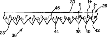
As shown in Figure 2, first light changed course element 26 is printing opacity optical thin films, and wherein, output surface 30 is the plane basically, and input surface 28 is formed with by prism 38,40 and 42 arrays of forming 36.Second light changed course element 32 is light transmission film also, and for example such as the brightness enhanced film of 3M brightness enhanced film product (selling with trade mark BEFIII), this product is produced by the 3M company in Sao Paulo, Minnesota.Reflective polarizer 34 can be liquid crystal reflective polariscope or a film one inorganic, polymkeric substance, cholesterol (cholesteric).Suitable film is 3M diffuse reflection formula polariscope film product (selling with trade mark DRF) or reflection type mirror polariscope film product (selling with trade mark DBEF), and both produce by 3M company.
More specifically referring to Fig. 2, in array 36, each prism 38,40 is compared with its each adjacent prism with 42, is formed with corner inequality.In other words, prism 38 is made up of the corner (angle A and B) that is different from prism 40 (angle C and D) and prism 42 (angle E and F).As shown in the figure, prism 38 has a prism angle, that is, this angle equals angle A and B sum.Same, prism 40 has a prism angle to equal angle C and B sum, and prism 42 has a prism angle to equal angle E and F sum.Although array 36 comprises three different prism structures based on different prism angles as shown in the figure, should be appreciated that, in fact can use any amount of different prism.
Clocklike repeating prism pattern or cohort 43 is arranged, and array 36 is not illustrated as identical prism in abutting connection with identical prism to prism 38,40 and 42 in array 36 as shown in Figure 2, and this structure also can be used.And in array 36, prism 38,40 and 42 changes serially, and from first prism structure of for example prism structure 38, to for example second prism structure of prism structure 40, the rest may be inferred.For example, the mode that prism structure can gradient changes, from first prism structure to second prism structure.Perhaps, prism changes in mode step by step, is similar to structure shown in Figure 2.In each cohort 43, prism has a prism pitch, and it is chosen for less than the space ripple frequency.The cohort spacing that one rule similarly, should be arranged between each cohort.
Although array as shown in Figure 2 36 has the prism of tool symmetrical structure, for example as shown in Figure 3, go up the array 36 ' that forms at light changed course element 26 ', also may be utilized.With reference to Fig. 3, in array 36 ', for example, the angle A ' of prism 38 ' is not equal to angle B ' then.Similarly, for prism 40 ' and 42 ', angle C ' is not equal to angle A ' and angle D ', and angle E ' is not equal to any among angle A ', angle C ' or the angle F '.Use one has the single diamond cutting tool of predetermined angular, makes it to tilt when each cutting, just can obtain to have different prism angles and symmetric prism, thereby can form array 36 ' expediently.Yet, there is any it being understood that and adopts single cutting tool, the prism angle will be identical, i.e. A+B=C+D=E+F.
Adopt few different prism structures to two although the size that can adopt multiple prism with the remodeling of the output shape that realizes light pipe 16, also can be imagined, and be arranged in each cohort in the array 36.The purpose that the prism corner changes is during distribution and the variable quantity that adds luminous energy alter course element 26 to first light.The structure of prism 38,40 and 42 variation can be used to provide the basic sampling uniformly to the light pipe input port, and it makes the unevenness in the light that extracts from light pipe 16 reduce to minimum degree.Net result is effectively moire effect to be reduced to minimum level, especially at inlet end 21 places near light pipe 16.
Referring to accompanying drawing 4, there is shown and constrain in two non-parallel mirror surfaces, for example, the stretch-out view of the light path between the TIR mirror surface in wedge-shaped light guide.One of them represents one to experience repeatedly the light that TIR reflects, and its is as a straight line that passes a plurality of images on light pipe surface.Therefore, be deposited in by a series of wedge xsects and be configured to sector structure together, wherein, left margin has constituted the input surface and its reflected image of light pipe.Along with light is removed from importing the surface, facing to constraint angle increase by one amount that equates with the angle of wedge of each mirror plane.On behalf of a light, top boundary extract the surface out, no matter be the top of light pipe or the end of light pipe, light is by the inhibition of TIR there, outgoing from light pipe and enter into air.Observe light pipe by this way, light path is straight line and order of reflection TIR is counted easily.The light that makes extraction that also can track is got back to its starting point on input hole.
Light sends from wedge in about 5 ° to 23 ° of angular range.This lower limit is the starting value that is subjected to press down the TIR transmission, by chance after the constraint angle surpasses the limit value of TIR.The representative of bigger angle is by intensity, this be since in the constraint angle that increases progressively the result that exhausts of reflex behavior repeatedly.Accurate light extraction scope depends on the angle of wedge and optical coefficient.
In Fig. 4 a, light 403 and 404 is drawn out of, and has the identical relay lens in abutting connection with prism 401 by one then and turns to an observer.Light 403 approximately is the lower limit of emergent light line chart line, yet is redirect to light path 405 by prism 401 that the about and normal direction angle of cut is-7.5 ° with respect to the about 5 ° of angle outgoing in this plane (with respect to 85 ° of normals).Light 404 is the higher limit of emergent light line chart line with about 23 ° of angle outgoing (with respect to 67 ° of normals), is redirect to light path 406 by prism 401 then, and the about and normal direction angle of cut is 10 °.
If the light 403 and 405 point B from the emitting surface and some A respectively sends, then an observer 407 at the drift angle of light 405 and 406 can see the FR emission ray plot line between an A and the some B.Light 401 and 402 within light pipe, refers to go back to the input surface to wedge.We see that the starting point of these extraneous lights separated by the width of 20 input holes on the fan-shaped left margin.Therefore, as observer 407 during from an A sweep to some B, he sees 20 times imaging of wedge input hole.If the light between from the lamp to the input hole connect be the space or angle all be heterogeneous, then observed heterogeneity is a ripple type.
The present invention considers is polygon prism structure and the effect of this structure on the light output uniformity in the relay lens of adjacency.For example, turning film has the cohort of prism structures, and each prism angle is 68.88 °, but can have different prism axes orientation with respect to the normal of relay lens, and angle is-1.5 °, 0 ° and 1.5 °.From three light that the observer draws, every prism that enters in the cohort, these three light will track by the index path that launches and get back to the diverse location place on input surface.With reference to Fig. 5, on the output surface of wedge, show and understand three positions " A ", " B " and " C ".On each position, the pencil of 3 light from output surface extend the input surperficial pupil fan-shaped in.See that as Fig. 5 even from the position " A " of the most close lamp one end, pencil also can cover the width of whole pupil.Therefore, provide the sampling of closely packed pupil, it causes the soft property of local repressentation brightness.The details and the optical index of wedge geometric configuration depended in the optical design of prism structure.
So far the prism cohort 43 of Tao Luning all has similar substantially structure.That is to say that same number of prism has the distribution of same prism structure.This is not a kind of requirement, and cohort 43 can structurally change.This layout can reduce this possibility, that is, although the difference of input angle is very little, in certain position, to certain angle, the aperture sampling can occur in almost same aperture position.This can cause the figure line of the local interference pattern similar to ripple.
The prism angle scope is from 30 °-120 °, but can be 40 °-75 °, can also be 60 °-75 °.Differential seat angle between the prism in cohort can be approximately 1 °-10 °, also can further be approximately 1 °-5 °.The spacing of prism, i.e. prism distance as discussed abovely should can also can further can be 30 μ m-50 μ m from 20 μ m-100 μ m from 1 μ m-1000 μ m in any case less than the ripple spatial frequency.Prism also can be approximately 150 μ m apart from the array distance that is the array 36 of 50 μ m.Because the effect of plane of refraction and at the TIR of reflecting surface, prism structure also is subjected to the influence of the refractive index of optical transmission film.The ranges of indices of refraction of typical membraneous material is 1.35-1.75.For example refractive index is 1.586 makrolon material, and the light of nominal to send (plunder and penetrate) angle be 13 ° light pipe, can adopt the nominal angle is 68.9 ° prism structure.
Referring now to Fig. 6, the turning film 44 that forms by another embodiment of the present invention is included in the prism array 45 on the input surface 46.This prism array 45 has the prism 47 that has first structure and second structure at least, and above-mentioned two kinds of structures are intended to reduce moire effect.And prism 47 is formed with the reflecting surface 48 of an arc.Prism angle is defined as the tangent line of reflecting surface 48 and the angle between the plane of refraction 49.As mentioned above, for array 36, for reducing moire effect, prism is arranged in the array 44 with being become cohort.In each cohort, prism angle can change and/or the orientation (being the angle of prism axis and normal) of prism can change.Should be understood that: two kinds of surfaces of formation should be the arcwall face structures.
The film (for example array 36,36 ' or 44) that comprises a prism array can be by extruding or cast and curing process formation.By diamond array structure is processed into cylinder blank or roller, at first to form master mold.A kind of technology that forms array structure on this surface is well-known screw chasing.First screw chasing goes out the length of roller bearing, and first screw thread is corresponding to first prism structure.From being adjacent to the position of first screw thread, cut second screw thread.When cutting second screw thread, use different cutting tools or adjust cutting tool for producing second prism structure.This repeatedly process changes cutting tool and/or adopts multiple cutter, till all desirable prism structures form.
Perhaps, use a kind of adjustable cutting tool, this cutter can be adjusted in the process of screw cutting.Cut single screw thread, cutter rotates continuously in working angles, thereby changes prism structure continuously, has so just formed all prisms in having the array of different prism structures.
Also having another kind of job operation is traverse feed ground cutting prism structure.The traverse feed cutting method can use multiple cutting tool to realize, and is a kind of corresponding to a kind of prism structure.A kind of adjustable cutting tool may be utilized, and to for every kind of prism structure of cutting, constantly adjusts cutter.
The possibility that another kind shapes comprises uses a kind of fast tool servo (FTS) actuator.A kind of diagram of FTS actuator and description, can be referring among the common Application No. No. () that transfers the possession of, be entitled as " optical thin film " (attorney docket No.53772USA6A) and Application No. No. () and be entitled as " optical thin film that surface imperfection reduces and preparation method thereof " (attorney docket No.7780374US01), for the purpose of reference, specially introduced above-mentioned public technology here.
The United States Patent (USP) application is described as previously mentioned, and FTS can advantageously be dissolved into moisture-resistant and/or other character in the array 36.Moist (wet-out) is the optical defect that occurs when two adjacent optical surfaces contact with each other in the display device.In order to prevent humidity, United States Patent (USP) is used described as previously mentioned, can on one or two surface in two adjacently situated surfaces, form the Feng Hegu of stochastic distribution, promptly local minimum and maximum, with contact area and the regularity between the minimum level minimizing adjacently situated surfaces.Like this, the input surface of first light changed course element 26 can form as comprising the moisture resistance structure that wets, and output surface is like this too.
Form the part of lighting devices 50 referring now to lighting device shown in Figure 7 50, one light pipes 52, it comprises that one first enters surface 54,1 second and enters surface 56, one output surface 58 and a back of the body surface 60.First light source 62 comprises one first light source reflector 64 and enters the surface and 54 be connected with first.Secondary light source 66 comprises a secondary light source reverberator 68 and enters the surface and be connected with second.First light changed course element 70 is arranged on contiguous output surface 58 places.First light changed course element 70 comprises an input surface 72 and one output surface 74.This lighting device 50 also comprise one with reverberator 76, the one second light changed course element 78 and a reflective polarizer 80 of surperficial 60 adjacency of the back of the body.Light pipe 52 can be wedge type or its remodeling.As everyone knows, the purpose of light pipe 50 be from two light sources 62 and 66 to more than the big many areas of the area of light source propagating light effectively own, more specifically, be the whole area that output surface 58 forms basically.
First light changed course element 70 is preferably a light transmission film, and its input surface 72 is formed with prism array in the mode similar to the array 36 of above-mentioned first light changed course element 26.Because lighting device 50 has a light source that is arranged on two ends, thereby the structure that forms prism array can be also can being asymmetric and having different prism angles of symmetry.This can guarantee to turn to along required observation axis from entering surface 54 and 56 light that enter light pipe 52.This prism array plays the effect along a preferred direction of observation changed course of the light that will come out from light pipe 52, also play the effect that reduces the ripple sensation.
The result who illuminates light pipe from both sides is that light enters from two relative surfaces 54 and 56 that enter, and can produce a kind of defective of light at the core 82 of light pipe 52.The prism array that forms on the input surface 72 of light changed course structure 70 can change at corresponding core 84, reduces this realizable optical defect to reduce the same mode of sensation ripple with array.
In view of above-mentioned description, the embodiment of modifications and variations of the present invention is to understand obviously to those skilled in the art.This description its objective is that only in order to illustrate the those skilled in the art of church realize the present invention in the mode of the best.Substantially do not breaking away under the prerequisite of spirit of the present invention, the details of structure and method can change, and keeps the proprietary application power of all modifications within the scope of the appended claims.
Claims (20)
1. optical inversion film, described optical inversion film have a first surface and one and described first surface opposing second surface that is formed with each prism, it is characterized in that,
Described each prism forms in the prism array in described first surface on the throne, described prism array is limited by a plurality of first prisms and a plurality of second prism, each first prism has one first prism structure, and each second prism has second prism structure different with first prism structure; The light that wherein incides described first surface is reflected by described a plurality of first prisms and a plurality of second prism and reflects along a preferred axis of observing.
2. optical inversion film as claimed in claim 1 is characterized in that, a plurality of first prisms and a plurality of second prism are arranged in each interior cohort of array.
3. optical inversion film as claimed in claim 1, it is characterized in that, a plurality of first prisms comprise at least one group of first prism with first prism structure, a plurality of second prisms comprise at least one group of second prism with second prism structure, and it is formed on the first surface of contiguous at least one group first prism.
4. optical inversion film as claimed in claim 3 is characterized in that, a plurality of first prisms comprise that another group at least has first prism of first prism structure, and it is formed on the first surface of contiguous at least one group second prism.
5. optical inversion film as claimed in claim 2 is characterized in that, a plurality of first prisms are inserted in a plurality of second prisms.
6. optical inversion film as claimed in claim 1 is characterized in that, first prism has one first dissymmetrical structure and second prism has second dissymmetrical structure different with first dissymmetrical structure.
7. optical inversion film as claimed in claim 1 is characterized in that, first prism has one first prism angle and second prism has second prism angle different with first prism angle.
8. optical inversion film as claimed in claim 7 is characterized in that, first prism angle and second prism angle are all in 30 °-120 ° scope.
9. optical inversion film as claimed in claim 1 is characterized in that, a plurality of first prisms and a plurality of second prism are separated by the prism distance, and wherein the scope of prism distance is at 1 μ m-1000 μ m.
10. optical inversion film as claimed in claim 9 is characterized in that, a plurality of first prisms and a plurality of second prism wherein have the cohort spacing with the arranged in form of cohort between cohort.
11. optical inversion film as claimed in claim 1, it is characterized in that, array comprises the transition portion between in a plurality of first prisms one and a plurality of second prism one, and this transition portion comprises from the continuous again configuration structure of first prism structure to second prism structure.
12. optical inversion film as claimed in claim 11 is characterized in that, a plurality of first prisms and a plurality of second prism are with the arranged in form of cohort, and wherein each cohort comprises at least one described transition portion.
13. optical inversion film as claimed in claim 1 is characterized in that, at least one in first prism structure and second prism structure comprises an arcwall face.
14. optical inversion film as claimed in claim 1 is characterized in that, each first prism structure and second prism structure comprise the Feng Hegu of stochastic distribution.
15. optical inversion film as claimed in claim 1 is characterized in that, a plurality of first prisms and a plurality of second prism have prism peaks respectively, and wherein prism peaks is alignd with the longitudinal axis of diaphragm.
16. optical inversion film as claimed in claim 1 is characterized in that, first prism has one first dissymmetrical structure and second prism structure different with first dissymmetrical structure.
17. a lighting device has a light pipe, this light pipe has an input surface and an output surface, wherein is incident upon the lip-deep light of input, extracts out at output surface with the glancing angle with respect to output surface by the total internal reflection that is subjected to press down; One is connected in described input surface ray cast is arrived the lip-deep light source of input; And a turning film, this turning film has the described structure of each claim as described above.
18. lighting device as claimed in claim 17 is characterized in that, the second surface of turning film is connected optically with display device.
19. lighting device as claimed in claim 18 is characterized in that, comprises that further one is arranged on the light changed course structure between turning film and the display device.
20. lighting device as claimed in claim 17 is characterized in that, the longitudinal axis alignment of first prism and second prism and turning film.
Applications Claiming Priority (2)
| Application Number | Priority Date | Filing Date | Title |
|---|---|---|---|
| US09/415,873 | 1999-10-08 | ||
| US09/415,873 US6356391B1 (en) | 1999-10-08 | 1999-10-08 | Optical film with variable angle prisms |
Publications (2)
| Publication Number | Publication Date |
|---|---|
| CN1378653A CN1378653A (en) | 2002-11-06 |
| CN1171100C true CN1171100C (en) | 2004-10-13 |
Family
ID=23647565
Family Applications (1)
| Application Number | Title | Priority Date | Filing Date |
|---|---|---|---|
| CNB008139695A Expired - Fee Related CN1171100C (en) | 1999-10-08 | 2000-09-01 | Optical film with variable angle prisms |
Country Status (7)
| Country | Link |
|---|---|
| US (3) | US6356391B1 (en) |
| EP (1) | EP1218776A1 (en) |
| JP (1) | JP2003511735A (en) |
| KR (1) | KR100867160B1 (en) |
| CN (1) | CN1171100C (en) |
| AU (1) | AU7349300A (en) |
| WO (1) | WO2001027663A1 (en) |
Families Citing this family (156)
| Publication number | Priority date | Publication date | Assignee | Title |
|---|---|---|---|---|
| US6752505B2 (en) | 1999-02-23 | 2004-06-22 | Solid State Opto Limited | Light redirecting films and film systems |
| US7364341B2 (en) * | 1999-02-23 | 2008-04-29 | Solid State Opto Limited | Light redirecting films including non-interlockable optical elements |
| US20050024849A1 (en) * | 1999-02-23 | 2005-02-03 | Parker Jeffery R. | Methods of cutting or forming cavities in a substrate for use in making optical films, components or wave guides |
| KR100323827B1 (en) * | 1999-06-07 | 2002-02-19 | 구본준, 론 위라하디락사 | Backlight device |
| US6845212B2 (en) * | 1999-10-08 | 2005-01-18 | 3M Innovative Properties Company | Optical element having programmed optical structures |
| US6356391B1 (en) * | 1999-10-08 | 2002-03-12 | 3M Innovative Properties Company | Optical film with variable angle prisms |
| US7046905B1 (en) * | 1999-10-08 | 2006-05-16 | 3M Innovative Properties Company | Blacklight with structured surfaces |
| US6570710B1 (en) | 1999-11-12 | 2003-05-27 | Reflexite Corporation | Subwavelength optical microstructure light collimating films |
| CA2393260A1 (en) | 1999-12-02 | 2001-06-21 | Reflexite Corporation | Asymmetric alternating prism arrays |
| JP3543951B2 (en) * | 2000-06-22 | 2004-07-21 | 日本電気株式会社 | Image display device |
| CN100389017C (en) * | 2000-08-18 | 2008-05-21 | 瑞弗莱克塞特公司 | Differentaially cured materials and process for forming same |
| US7230764B2 (en) * | 2000-08-18 | 2007-06-12 | Reflexite Corporation | Differentially-cured materials and process for forming same |
| US20040190102A1 (en) * | 2000-08-18 | 2004-09-30 | Mullen Patrick W. | Differentially-cured materials and process for forming same |
| GB0029340D0 (en) * | 2000-11-30 | 2001-01-17 | Cambridge 3D Display Ltd | Flat panel camera |
| US6903788B2 (en) * | 2001-07-05 | 2005-06-07 | Nitto Denko Corporation | Optical film and a liquid crystal display using the same |
| US7859759B2 (en) * | 2002-05-20 | 2010-12-28 | Sabic Innovative Plastics Ip B.V. | Film, backlight displays, and methods for making the same |
| US6862141B2 (en) * | 2002-05-20 | 2005-03-01 | General Electric Company | Optical substrate and method of making |
| US7180672B2 (en) * | 2002-05-20 | 2007-02-20 | General Electric Company | Optical substrate and method of making |
| US7010212B2 (en) * | 2002-05-28 | 2006-03-07 | 3M Innovative Properties Company | Multifunctional optical assembly |
| US7624783B2 (en) * | 2006-07-12 | 2009-12-01 | Sensenig Luke G | Curtain system for domestic animal shelter |
| US7437980B2 (en) * | 2002-05-29 | 2008-10-21 | Massachusetts Institute Of Technology | Flux-biased electromagnetic fast tool servo systems and methods |
| US7765905B2 (en) * | 2002-05-29 | 2010-08-03 | Massachusetts Institute Of Technology | Magnetic micropositioner and method of providing the same |
| US7574947B2 (en) * | 2002-05-29 | 2009-08-18 | Massachusetts Institute Of Technology | Rotary fast tool servo system and methods |
| US7275468B2 (en) * | 2002-05-29 | 2007-10-02 | Massachusetts Institute Of Technology | Rotary fast tool servo system and methods |
| US6811274B2 (en) * | 2002-12-04 | 2004-11-02 | General Electric Company | Polarization sensitive optical substrate |
| US7125131B2 (en) * | 2002-12-06 | 2006-10-24 | General Electric Company | Brightness enhancement film with improved view angle |
| US6952627B2 (en) * | 2002-12-18 | 2005-10-04 | General Electric Company | Method and apparatus for fabricating light management substrates |
| WO2004088403A1 (en) | 2003-03-28 | 2004-10-14 | Seiko Epson Corporation | Spatial light modulation device, projector using the spatial light modulation device, method for manufacturing fine-structure element used in the spatial light modulation device, and fine-structure element manufactured by the method |
| JP2006525553A (en) * | 2003-05-02 | 2006-11-09 | リフレキサイト コーポレイション | Optical reorientation optical structure |
| US7074463B2 (en) | 2003-09-12 | 2006-07-11 | 3M Innovative Properties Company | Durable optical element |
| US7282272B2 (en) * | 2003-09-12 | 2007-10-16 | 3M Innovative Properties Company | Polymerizable compositions comprising nanoparticles |
| US7289202B2 (en) * | 2004-09-10 | 2007-10-30 | 3M Innovative Properties Company | Methods for testing durable optical elements |
| JP2007505359A (en) * | 2003-09-12 | 2007-03-08 | スリーエム イノベイティブ プロパティズ カンパニー | Durable optical element |
| US20060249370A1 (en) * | 2003-09-15 | 2006-11-09 | Makoto Nagashima | Back-biased face target sputtering based liquid crystal display device |
| US20050057913A1 (en) * | 2003-09-16 | 2005-03-17 | Dennis Brett M. | Backlight having multiple intensity maxima |
| WO2005043266A2 (en) * | 2003-10-31 | 2005-05-12 | Massachusetts Institute Of Technology | Variable reluctance fast positioning system and methods |
| TWI328702B (en) * | 2003-11-04 | 2010-08-11 | Hon Hai Prec Ind Co Ltd | Backlight system |
| KR100717499B1 (en) * | 2003-11-12 | 2007-05-14 | 엘지전자 주식회사 | Prism sheet, back light assembly and display device |
| US20050130759A1 (en) * | 2003-12-12 | 2005-06-16 | Hayden Mark X. | Sports shaft with variable contour |
| WO2005059604A1 (en) * | 2003-12-17 | 2005-06-30 | Mitsubishi Denki Kabushiki Kaisha | Fresnel optical element and projection type display device |
| US7303322B2 (en) * | 2003-12-23 | 2007-12-04 | 3M Innovative Properties Company | Multiple lightguide backlight |
| US7072092B2 (en) * | 2003-12-31 | 2006-07-04 | General Electric Company | Optical substrate with modulated structure |
| JP2005234402A (en) * | 2004-02-20 | 2005-09-02 | Citizen Electronics Co Ltd | Backlight |
| JP2005265894A (en) * | 2004-03-16 | 2005-09-29 | Fuji Photo Film Co Ltd | Condensing filter |
| US20050237749A1 (en) * | 2004-04-22 | 2005-10-27 | 3M Innovative Properties Company | Transflector |
| US7160017B2 (en) | 2004-06-03 | 2007-01-09 | Eastman Kodak Company | Brightness enhancement film using a linear arrangement of light concentrators |
| TWI304486B (en) | 2006-10-19 | 2008-12-21 | Efun Technology Co Ltd | Brightness enhancement film having curved prism units and matte |
| KR101136587B1 (en) | 2004-07-27 | 2012-04-18 | 돌비 레버러토리즈 라이쎈싱 코오포레이션 | Diffuser for light from light source array and displays incorporating same |
| US7203569B2 (en) * | 2004-08-31 | 2007-04-10 | General Electric Company | Machine tool control methods and designs for fabricating mesoscopic surface structures on substrates |
| US7775700B2 (en) * | 2004-10-01 | 2010-08-17 | Rohm And Haas Electronics Materials Llc | Turning film using array of roof prism structures |
| TWI253525B (en) * | 2004-10-07 | 2006-04-21 | Au Optronics Corp | Polarization optical device and liquid crystal display module utilizing the same |
| US20060083004A1 (en) * | 2004-10-15 | 2006-04-20 | Eastman Kodak Company | Flat-panel area illumination system |
| KR20070085643A (en) * | 2004-11-04 | 2007-08-27 | 솔리드 스테이트 옵토 리미티드 | Long curved wedges in an optical film |
| GB0427607D0 (en) | 2004-12-16 | 2005-01-19 | Microsharp Corp Ltd | Structured optical film |
| US20060138686A1 (en) * | 2004-12-23 | 2006-06-29 | Ouderkirk Andrew J | Method of making a uniaxially stretched polymeric film having structured surface |
| US20060141220A1 (en) * | 2004-12-23 | 2006-06-29 | Merrill William W | Uniaxially oriented article having a structured surface |
| US20060138705A1 (en) * | 2004-12-23 | 2006-06-29 | Korba Gary A | Method of making a structured surface article |
| US20060204720A1 (en) * | 2004-12-23 | 2006-09-14 | Biernath Rolf W | Uniaxially oriented birefringent article having a structured surface |
| US20060141219A1 (en) * | 2004-12-23 | 2006-06-29 | Benson Olester Jr | Roll of a uniaxially oriented article having a structured surface |
| US20060141218A1 (en) * | 2004-12-23 | 2006-06-29 | Biernath Rolf W | Uniaxially oriented articles having structured surface |
| US20060138694A1 (en) * | 2004-12-23 | 2006-06-29 | Biernath Rolf W | Method of making a polymeric film having structured surfaces via replication |
| US20060138702A1 (en) * | 2004-12-23 | 2006-06-29 | Biernath Rolf W | Method of making uniaxially oriented articles having structured surfaces |
| JP4553726B2 (en) * | 2004-12-28 | 2010-09-29 | 富士通株式会社 | Rod-shaped light guide, illumination device, and liquid crystal display device |
| US7241437B2 (en) * | 2004-12-30 | 2007-07-10 | 3M Innovative Properties Company | Zirconia particles |
| US7384173B2 (en) * | 2004-12-30 | 2008-06-10 | 3M Innovative Properties Company | Brightness enhancement article |
| WO2006088930A2 (en) * | 2005-02-17 | 2006-08-24 | 3M Innovative Properties Company | Brightness enhancement film comprising polymerized organic phase having low glass transition temperature |
| US7326448B2 (en) | 2005-02-17 | 2008-02-05 | 3M Innovative Properties Company | Polymerizable oligomeric urethane compositions comprising nanoparticles |
| US20060204679A1 (en) * | 2005-03-11 | 2006-09-14 | 3M Innovative Properties Company | Polymerizable compositions comprising nanoparticles |
| US20060204676A1 (en) * | 2005-03-11 | 2006-09-14 | Jones Clinton L | Polymerizable composition comprising low molecular weight organic component |
| JP2008533525A (en) * | 2005-03-11 | 2008-08-21 | スリーエム イノベイティブ プロパティズ カンパニー | Light control film having zirconia particles |
| TWI255924B (en) * | 2005-03-16 | 2006-06-01 | Au Optronics Corp | Backlight module and brightness enhancement film thereof |
| EP1872161B1 (en) | 2005-04-08 | 2009-09-09 | 3M Innovative Properties Company | Structured oriented films for use in displays |
| CN100399146C (en) * | 2005-04-08 | 2008-07-02 | 友达光电股份有限公司 | Backlight module and its brightness raising film |
| US20060257678A1 (en) * | 2005-05-10 | 2006-11-16 | Benson Olester Jr | Fiber reinforced optical films |
| US7400445B2 (en) * | 2005-05-31 | 2008-07-15 | 3M Innovative Properties Company | Optical filters for accelerated weathering devices |
| US7379245B2 (en) * | 2005-06-06 | 2008-05-27 | 3M Innovative Properties Company | Articles including films with mating structured surfaces |
| CN101218519B (en) * | 2005-06-09 | 2010-09-08 | 友辉光电股份有限公司 | Moire-reducing optical substrates with irregular prism structures |
| US20070019434A1 (en) * | 2005-07-22 | 2007-01-25 | Eastman Kodak Company | Turning film having variable pitch |
| JP2007041583A (en) * | 2005-07-30 | 2007-02-15 | Samsung Electronics Co Ltd | Polarization compensation film, manufacturing method of polarizing prism film, display panel assembly and display device |
| US7418202B2 (en) * | 2005-08-04 | 2008-08-26 | 3M Innovative Properties Company | Article having a birefringent surface and microstructured features having a variable pitch or angles for use as a blur filter |
| US20070065636A1 (en) * | 2005-08-04 | 2007-03-22 | Merrill William W | Article having a birefringent surface and microstructured features having a variable pitch or angles and process for making the article |
| TWI391711B (en) * | 2005-09-13 | 2013-04-01 | Efun Technology Co Ltd | Brightness enhancement film having a light-guiding layer |
| US20070058391A1 (en) * | 2005-09-14 | 2007-03-15 | Wilson Randall H | Light extraction layer |
| US7663712B2 (en) * | 2005-10-10 | 2010-02-16 | Skc Haas Display Films Co., Ltd. | Backlight unit with linearly reduced divergence having the width of an output aperture vary over the length of a light divergence reduction structure |
| GB2431728A (en) * | 2005-10-31 | 2007-05-02 | Sharp Kk | Multi-depth displays |
| US7350442B2 (en) * | 2005-11-15 | 2008-04-01 | 3M Innovative Properties Company | Cutting tool having variable movement in a z-direction laterally along a work piece for making microstructures |
| US7293487B2 (en) * | 2005-11-15 | 2007-11-13 | 3M Innovative Properties Company | Cutting tool having variable and independent movement in an x-direction and a z-direction into and laterally along a work piece for making microstructures |
| US7290471B2 (en) * | 2005-11-15 | 2007-11-06 | 3M Innovative Properties Company | Cutting tool having variable rotation about a y-direction transversely across a work piece for making microstructures |
| US7350441B2 (en) * | 2005-11-15 | 2008-04-01 | 3M Innovative Properties Company | Cutting tool having variable movement at two simultaneously independent speeds in an x-direction into a work piece for making microstructures |
| US7575152B2 (en) * | 2005-11-15 | 2009-08-18 | E2Interactive, Inc. | Temporary value card method and system |
| US7712944B2 (en) * | 2005-12-06 | 2010-05-11 | Ubright Optronics Corporation | Luminance enhancement optical substrates with anti-chatter structures |
| US20070133226A1 (en) * | 2005-12-13 | 2007-06-14 | Eastman Kodak Company | Polarizing turning film with multiple operating orientations |
| US7328638B2 (en) * | 2005-12-27 | 2008-02-12 | 3M Innovative Properties Company | Cutting tool using interrupted cut fast tool servo |
| US20070153384A1 (en) * | 2005-12-30 | 2007-07-05 | Ouderkirk Andrew J | Reinforced reflective polarizer films |
| US20070153162A1 (en) * | 2005-12-30 | 2007-07-05 | Wright Robin E | Reinforced reflective polarizer films |
| US7866871B2 (en) * | 2006-01-13 | 2011-01-11 | Avery Dennison Corporation | Light enhancing structures with a plurality of arrays of elongate features |
| US7674028B2 (en) | 2006-01-13 | 2010-03-09 | Avery Dennison Corporation | Light enhancing structures with multiple arrays of elongate features of varying characteristics |
| US7366393B2 (en) | 2006-01-13 | 2008-04-29 | Optical Research Associates | Light enhancing structures with three or more arrays of elongate features |
| US7452120B2 (en) | 2006-03-24 | 2008-11-18 | Rohm And Haas Denmark Finance A/S | Illumination apparatus and film |
| US20070236939A1 (en) * | 2006-03-31 | 2007-10-11 | 3M Innovative Properties Company | Structured Composite Optical Films |
| US20070237938A1 (en) * | 2006-03-31 | 2007-10-11 | 3M Innovative Properties Company | Reinforced Optical Films |
| US20070236938A1 (en) * | 2006-03-31 | 2007-10-11 | 3M Innovative Properties Company | Structured Composite Optical Films |
| KR20070103544A (en) * | 2006-04-19 | 2007-10-24 | 삼성전자주식회사 | Liquid crystal display and prism sheet for the same |
| US7777166B2 (en) * | 2006-04-21 | 2010-08-17 | Cree, Inc. | Solid state luminaires for general illumination including closed loop feedback control |
| US7677146B2 (en) * | 2006-05-10 | 2010-03-16 | 3M Innovative Properties Company | Cutting tool using one or more machined tool tips in a continuous or interrupted cut fast tool servo |
| US9134471B2 (en) | 2006-06-28 | 2015-09-15 | 3M Innovative Properties Company | Oriented polymeric articles and method |
| KR101471213B1 (en) * | 2006-06-30 | 2014-12-12 | 유브라이트 옵트로닉스 코포레이션 | Luminance enhancement optical substrates with optical defect masking structures |
| US20080101759A1 (en) * | 2006-10-26 | 2008-05-01 | K Laser Technology, Inc. | Prism matrix with random phase structures |
| US20080129930A1 (en) * | 2006-12-01 | 2008-06-05 | Agoura Technologies | Reflective polarizer configuration for liquid crystal displays |
| KR101354358B1 (en) * | 2006-12-27 | 2014-01-23 | 엘지디스플레이 주식회사 | Optical plate and backlight assembly having the same |
| US7628100B2 (en) * | 2007-01-05 | 2009-12-08 | 3M Innovative Properties Company | Cutting tool using one or more machined tool tips with diffractive features in a continuous or interrupted cut fast tool servo |
| KR100905241B1 (en) * | 2007-04-13 | 2009-07-01 | 엘지전자 주식회사 | Optical film having a plurality of structures and backlight unit including the same |
| US7530721B2 (en) * | 2007-04-18 | 2009-05-12 | Skc Haas Display Films Co., Ltd. | Double-sided turning film |
| US20080285304A1 (en) | 2007-05-18 | 2008-11-20 | Rankin Jr Charles M | Light extraction film system |
| KR100873500B1 (en) * | 2007-06-12 | 2008-12-15 | 제일모직주식회사 | Light guide panel comprising symmetric front prism and asymmetric front prism for back light unit of lcd |
| US7669508B2 (en) * | 2007-10-29 | 2010-03-02 | 3M Innovative Properties Company | Cutting tool using one or more machined tool tips with diffractive features |
| EP2205665B1 (en) * | 2007-10-31 | 2012-10-17 | DuPont Teijin Films U.S. Limited Partnership | Coated articles |
| US20090147361A1 (en) * | 2007-12-07 | 2009-06-11 | 3M Innovative Properties Company | Microreplicated films having diffractive features on macro-scale features |
| CN101452144A (en) * | 2007-12-07 | 2009-06-10 | 旭丽电子(广州)有限公司 | Optical assembly |
| JP5827120B2 (en) | 2008-04-02 | 2015-12-02 | スリーエム イノベイティブ プロパティズ カンパニー | Light guide film and method for producing light guide film |
| TW200946975A (en) * | 2008-04-02 | 2009-11-16 | 3M Innovative Properties Co | Methods and systems for fabricating optical films having superimposed features |
| JP5272508B2 (en) * | 2008-05-12 | 2013-08-28 | 凸版印刷株式会社 | Optical sheet, backlight unit and display device |
| US20090322800A1 (en) | 2008-06-25 | 2009-12-31 | Dolby Laboratories Licensing Corporation | Method and apparatus in various embodiments for hdr implementation in display devices |
| US8098347B2 (en) * | 2008-11-21 | 2012-01-17 | 3M Innovative Properties Company | Stereoscopic 3D liquid crystal display with graded light guide light extraction features |
| KR101184447B1 (en) * | 2008-12-15 | 2012-09-20 | 제일모직주식회사 | Extrusion moding method of prism film and prism film manufactured by same method |
| US20100184616A1 (en) * | 2009-01-20 | 2010-07-22 | Bio-Rad Laboratories, Inc. | Spatially controlled illumination of biological sample array through wedge-shaped support |
| US8228463B2 (en) * | 2009-11-18 | 2012-07-24 | 3M Innovative Properties Company | Passive daylight-coupled backlight with turning film having prisms with chaos for sunlight viewable displays |
| US20110205756A1 (en) * | 2010-02-19 | 2011-08-25 | Pixtronix, Inc. | Light guides and backlight systems incorporating prismatic structures and light redirectors |
| TWI420051B (en) * | 2010-07-28 | 2013-12-21 | Hon Hai Prec Ind Co Ltd | Led surface illuminant device |
| US8610227B2 (en) * | 2010-10-13 | 2013-12-17 | Taiwan Semiconductor Manufacturing Co., Ltd. | Formation of embedded micro-lens |
| US8952364B2 (en) | 2011-11-10 | 2015-02-10 | Nitto Denko Corporation | Light-emitting devices comprising nanostructures |
| JP2013195893A (en) * | 2012-03-22 | 2013-09-30 | Stanley Electric Co Ltd | Three-dimensional display device |
| US9644814B2 (en) | 2012-05-03 | 2017-05-09 | Lighting Science Group Corporation | Luminaire with prismatic optic |
| US9255685B2 (en) | 2012-05-03 | 2016-02-09 | Lighting Science Group Corporation | Luminaire with prismatic optic |
| US8899776B2 (en) | 2012-05-07 | 2014-12-02 | Lighting Science Group Corporation | Low-angle thoroughfare surface lighting device |
| US8899775B2 (en) | 2013-03-15 | 2014-12-02 | Lighting Science Group Corporation | Low-angle thoroughfare surface lighting device |
| US9978953B2 (en) | 2012-08-31 | 2018-05-22 | Nitto Denko Corporation | Substituted biphenyl compounds for use in light-emitting devices |
| US9127818B2 (en) | 2012-10-03 | 2015-09-08 | Lighting Science Group Corporation | Elongated LED luminaire and associated methods |
| US9322516B2 (en) | 2012-11-07 | 2016-04-26 | Lighting Science Group Corporation | Luminaire having vented optical chamber and associated methods |
| US9459397B2 (en) | 2013-03-12 | 2016-10-04 | Lighting Science Group Corporation | Edge lit lighting device |
| US9255670B2 (en) | 2013-03-15 | 2016-02-09 | Lighting Science Group Corporation | Street lighting device for communicating with observers and associated methods |
| US9429294B2 (en) | 2013-11-11 | 2016-08-30 | Lighting Science Group Corporation | System for directional control of light and associated methods |
| KR101522242B1 (en) * | 2013-11-18 | 2015-05-21 | 엘지디스플레이 주식회사 | Optical sheet and liquid crystal display including the same |
| US9322178B2 (en) | 2013-12-15 | 2016-04-26 | Vkr Holdings A/S | Skylight with sunlight pivot |
| EP3126884A2 (en) | 2014-04-01 | 2017-02-08 | 3M Innovative Properties Company | Asymmetric turning film with multiple light sources |
| WO2015183604A1 (en) | 2014-05-30 | 2015-12-03 | 3M Innovative Properties Company | Temporally multiplexing backlight with asymmetric turning film |
| CN104570194A (en) * | 2014-12-31 | 2015-04-29 | 深圳市华星光电技术有限公司 | Light guide plate and display module |
| US10488014B2 (en) * | 2015-06-16 | 2019-11-26 | 3M Innovative Properties Company | Display including switchable backlight and front surface film |
| CN107949801A (en) | 2015-08-26 | 2018-04-20 | 3M创新有限公司 | Collimate ladder wedge light guide |
| KR102558671B1 (en) | 2016-03-31 | 2023-07-26 | 동우 화인켐 주식회사 | A blue photosensitive resin composition, blue color filter and display device comprising the same |
| CN106391508B (en) * | 2016-08-31 | 2019-07-09 | 合肥泰禾光电科技股份有限公司 | A kind of camera aligning tool of the included backlight for color selector |
| US10552690B2 (en) | 2016-11-04 | 2020-02-04 | X Development Llc | Intuitive occluded object indicator |
| US10558264B1 (en) | 2016-12-21 | 2020-02-11 | X Development Llc | Multi-view display with viewer detection |
| US10012356B1 (en) | 2017-11-22 | 2018-07-03 | LightLouver LLC | Light-redirecting optical daylighting system |
| US11906759B2 (en) | 2018-05-22 | 2024-02-20 | 3M Innovative Properties Company | Optical film with light control edge |
| WO2021134514A1 (en) * | 2019-12-31 | 2021-07-08 | 深圳Tcl新技术有限公司 | Backlight module, diffusion plate manufacturing method and display device |
Family Cites Families (124)
| Publication number | Priority date | Publication date | Assignee | Title |
|---|---|---|---|---|
| US586247A (en) | 1897-07-13 | Ments | ||
| US752429A (en) | 1904-02-16 | Prismatic illuminating structure | ||
| US586252A (en) | 1897-07-13 | Frank c | ||
| US607792A (en) | 1898-07-19 | Oswald e | ||
| US586220A (en) | 1897-07-13 | basquin | ||
| US586214A (en) | 1897-07-13 | Vault-light | ||
| US586249A (en) | 1897-07-13 | Light | ||
| US586248A (en) | 1897-07-13 | Vault-light | ||
| US586251A (en) | 1897-07-13 | soper | ||
| US720987A (en) | 1898-07-28 | 1903-02-17 | Pressed Prism Plate Glass Co | Illuminating glass structure. |
| US719066A (en) | 1898-10-28 | 1903-01-27 | Pressed Prism Plate Glass Co | Illuminating structure. |
| US755196A (en) | 1898-10-28 | 1904-03-22 | Pressed Prism Plate Glass Co | Illuminating structure. |
| US650209A (en) | 1899-04-14 | 1900-05-22 | James White | Protective hollow illuminating-tile. |
| US713182A (en) | 1899-05-27 | 1902-11-11 | Pressed Prism Plate Glass Co | Prismatic fireproof structure. |
| US720386A (en) | 1900-07-12 | 1903-02-10 | Pressed Prism Plate Glass Co | Illuminating prism structure. |
| US818208A (en) | 1905-06-17 | 1906-04-17 | Pressed Prism Plate Glass Co | Prism-glass. |
| US2179863A (en) | 1933-08-25 | 1939-11-14 | Holophane Co Inc | Light directing brick and walls and buildings utilizing the same |
| US2115178A (en) | 1934-07-28 | 1938-04-26 | Holophane Co Inc | Luminaire having means for reducing the apparent size of the light source |
| US2099034A (en) | 1935-04-25 | 1937-11-16 | Holophane Co Inc | Refractor |
| US2143148A (en) | 1937-01-26 | 1939-01-10 | Edwin F Guth | Light shield |
| US2223841A (en) | 1939-06-19 | 1940-12-03 | Day Brite Lighting Inc | Shielded lens |
| US2347665A (en) | 1941-03-04 | 1944-05-02 | Christensen Geneva Bandy | Internal reflection lighting means |
| US2398507A (en) | 1944-02-05 | 1946-04-16 | Holophane Co Inc | Down lighting apparatus |
| US2714816A (en) | 1949-06-27 | 1955-08-09 | Jane Booth Pennell | Building wall unit for an opaque and translucent corrugation surface |
| US2844998A (en) | 1954-10-21 | 1958-07-29 | Owens Illinois Glass Co | Glass building block having lightdirecting properties |
| GB806124A (en) | 1955-02-25 | 1958-12-17 | Gen Electric Co Ltd | Improvements in or relating to electric lighting arrangements for indoor illumination |
| US3721818A (en) | 1970-05-18 | 1973-03-20 | Ksh Inc | Ceiling mounted luminaire and light-transmitting enclosure therefor |
| BE787114A (en) | 1971-08-05 | 1973-02-05 | Emerson Electric Co | PRISMATIC LENS FOR LIGHTING DEVICES |
| JPS5189419A (en) | 1975-02-03 | 1976-08-05 | ||
| US4127693A (en) | 1975-02-10 | 1978-11-28 | Lemelson Jerome H | Reflex reflectors with pyramid-shaped indentations |
| US3994564A (en) | 1975-03-31 | 1976-11-30 | Hughes Aircraft Company | Light pipe reflector for use in liquid crystal or other display |
| JPS526496A (en) | 1975-07-04 | 1977-01-18 | Toshiba Corp | Liquid crystal indicator |
| JPS5825243B2 (en) | 1977-11-07 | 1983-05-26 | シャープ株式会社 | Transmissive fluorescent liquid crystal display device |
| JPS54127299A (en) | 1978-03-25 | 1979-10-03 | Citizen Watch Co Ltd | Lighting structure of photo detection type display unit |
| US4233651A (en) | 1978-03-30 | 1980-11-11 | Keene Corporation | Work area lighting system |
| CH633381A5 (en) | 1978-12-20 | 1982-11-30 | Bbc Brown Boveri & Cie | ELECTROOPTICAL DISPLAY WITH REFLECTOR. |
| US4242723A (en) | 1979-05-14 | 1980-12-30 | Keene Corporation | Low level work area lighting system |
| US4337759A (en) | 1979-10-10 | 1982-07-06 | John M. Popovich | Radiant energy concentration by optical total internal reflection |
| US4486070A (en) * | 1981-04-13 | 1984-12-04 | Polaroid Corporation | Mirror-absorber for use in the illumination of transmission holograms |
| JPS5817402A (en) | 1981-07-24 | 1983-02-01 | Kunishiro Kanagata Kogyo Kk | Shadowless prism plate |
| US4450509A (en) | 1982-08-17 | 1984-05-22 | Thorn Emi Plc | Lanterns for area lighting |
| US4870484A (en) | 1983-05-13 | 1989-09-26 | Seiko Epson Corporation | Color display device using light shutter and color filters |
| US4542449A (en) | 1983-08-29 | 1985-09-17 | Canadian Patents & Development Limited | Lighting panel with opposed 45° corrugations |
| JPH0766122B2 (en) | 1983-09-30 | 1995-07-19 | セイコーエプソン株式会社 | Transmissive liquid crystal display device |
| JPS6111782A (en) | 1984-06-27 | 1986-01-20 | 三菱レイヨン株式会社 | Image display |
| EP0167721B1 (en) | 1984-07-02 | 1989-10-11 | Mitsubishi Rayon Co., Ltd. | Light diffuser |
| JPS61158367A (en) | 1984-12-29 | 1986-07-18 | シャープ株式会社 | Lighting apparatus |
| CA1279783C (en) | 1985-11-21 | 1991-02-05 | Minnesota Mining And Manufacturing Company | Totally internally reflecting thin, flexible film |
| US4755921A (en) | 1986-04-02 | 1988-07-05 | Minnesota Mining And Manufacturing Company | Lens |
| US4804253A (en) | 1986-05-15 | 1989-02-14 | General Electric Company | Lenticular filter for display devices |
| JPS6310402A (en) | 1986-07-01 | 1988-01-18 | 株式会社 太陽エネルギ−研究所 | Lighting apparatus |
| JP2559579B2 (en) | 1986-09-03 | 1996-12-04 | 大日本印刷株式会社 | Surface light source |
| FR2606861B3 (en) | 1986-11-19 | 1989-02-03 | Richer Charles | METHOD FOR MANUFACTURING A DECORATIVE LAMP, AND DECORATIVE LAMP OBTAINED |
| US4984144A (en) | 1987-05-08 | 1991-01-08 | Minnesota Mining And Manufacturing Company | High aspect ratio light fixture and film for use therein |
| WO1989002606A1 (en) | 1987-09-09 | 1989-03-23 | Fandrich Heinz Juergen | Device composed of a light guide plate |
| CA1312320C (en) | 1987-11-12 | 1993-01-05 | Makoto Oe | Plane light source unit |
| JPH0833840B2 (en) | 1988-07-19 | 1996-03-29 | 富士通株式会社 | Error recovery procedure notification system |
| JP2605134B2 (en) | 1988-12-28 | 1997-04-30 | 三菱レイヨン株式会社 | Surface light source element |
| US5005108A (en) | 1989-02-10 | 1991-04-02 | Lumitex, Inc. | Thin panel illuminator |
| JPH02214822A (en) | 1989-02-16 | 1990-08-27 | Matsushita Electric Ind Co Ltd | Liquid crystal display element |
| US5040883A (en) | 1989-10-30 | 1991-08-20 | Minnesota Mining And Manufacturing Company | Light fixture with beam shaping lens |
| US5095415A (en) | 1989-10-30 | 1992-03-10 | Minnesota Mining And Manufacturing Company | Light fixture for externally illuminated sign |
| JPH03170911A (en) | 1989-11-30 | 1991-07-24 | Pioneer Electron Corp | Liquid crystal display device |
| JPH03184020A (en) | 1989-12-13 | 1991-08-12 | Sharp Corp | Liquid crystal display device |
| JPH03184021A (en) | 1989-12-13 | 1991-08-12 | Sharp Corp | Liquid crystal display device |
| JPH0627917B2 (en) | 1989-12-20 | 1994-04-13 | 京セラ株式会社 | Planar liquid crystal display |
| US5128783A (en) | 1990-01-31 | 1992-07-07 | Ois Optical Imaging Systems, Inc. | Diffusing/collimating lens array for a liquid crystal display |
| US5161041A (en) | 1990-04-26 | 1992-11-03 | Ois Optical Imaging Systems, Inc. | Lighting assembly for a backlit electronic display including an integral image splitting and collimating means |
| US5206746A (en) | 1990-07-12 | 1993-04-27 | Asahi Glass Company Ltd. | Transparent-scattering type optical device including a prism with a triangular longitudinal cross section |
| US5079675A (en) | 1990-11-08 | 1992-01-07 | Deilaito Co., Ltd. | Surface illuminating apparatus |
| EP0500089B1 (en) | 1991-02-21 | 1996-08-14 | Tosoh Corporation | Back lighting device |
| JP3191329B2 (en) | 1991-07-12 | 2001-07-23 | ヤマハ株式会社 | Upright piano shelf mounting structure |
| US5190370A (en) | 1991-08-21 | 1993-03-02 | Minnesota Mining And Manufacturing Company | High aspect ratio lighting element |
| DE69220870T2 (en) | 1991-08-22 | 1998-02-05 | Tosoh Corp | Rear lighting device |
| US5552907A (en) | 1992-01-27 | 1996-09-03 | Sekisui Chemical Co., Ltd. | Light adjusting sheet having a sinusoidal surface and a non-optically flat surface and useable with an LCD |
| CA2088113C (en) | 1992-01-27 | 1999-03-30 | Tomohiro Yokota | Light adjusting sheet for a planar lighting device and a planar lighting device and a liquid crystal display using the sheet |
| US6002829A (en) * | 1992-03-23 | 1999-12-14 | Minnesota Mining And Manufacturing Company | Luminaire device |
| US5528720A (en) | 1992-03-23 | 1996-06-18 | Minnesota Mining And Manufacturing Co. | Tapered multilayer luminaire devices |
| US5303322A (en) | 1992-03-23 | 1994-04-12 | Nioptics Corporation | Tapered multilayer luminaire devices |
| US5499138A (en) | 1992-05-26 | 1996-03-12 | Olympus Optical Co., Ltd. | Image display apparatus |
| CA2097109C (en) * | 1992-06-01 | 2000-01-11 | Shozo Kokawa | Liquid crystal display |
| JP3123006B2 (en) | 1992-06-30 | 2001-01-09 | 大日本印刷株式会社 | Surface light source and liquid crystal display |
| JPH0682635A (en) | 1992-07-07 | 1994-03-25 | Sekisui Chem Co Ltd | Surface light source device |
| US5280371A (en) | 1992-07-09 | 1994-01-18 | Honeywell Inc. | Directional diffuser for a liquid crystal display |
| JP2842739B2 (en) * | 1992-09-14 | 1999-01-06 | 富士通株式会社 | Surface light source unit and liquid crystal display device |
| JPH0695112A (en) | 1992-09-16 | 1994-04-08 | Hitachi Ltd | Prism plate and information display device formed by using this plate |
| JP3006306B2 (en) | 1992-09-16 | 2000-02-07 | インターナショナル・ビジネス・マシーンズ・コーポレイション | Optical film and liquid crystal display device using the optical film |
| TW594115B (en) | 1992-10-09 | 2004-06-21 | Asahi Glass Co Ltd | A liquid crystal display device and an illumination device for a direct viewing type display element |
| KR0168879B1 (en) | 1992-12-25 | 1999-04-15 | 기따지마 요시또시 | Renticular lens, surface light source and liquid crystal display apparatus |
| DE69418499T2 (en) | 1993-02-01 | 2000-02-10 | Tosoh Corp | Backlight device |
| JPH06242322A (en) | 1993-02-16 | 1994-09-02 | Enplas Corp | Surface light source device |
| US5598280A (en) | 1993-03-23 | 1997-01-28 | Dai Nippon Printing Co., Ltd. | Film lens and a surface light source using the same |
| JPH071428U (en) | 1993-06-04 | 1995-01-10 | 株式会社エンプラス | Surface light source |
| CA2099067C (en) | 1993-06-23 | 2001-02-13 | Makoto Oe | Plane light source unit |
| JP3184021B2 (en) | 1993-09-20 | 2001-07-09 | セイコーインスツルメンツ株式会社 | 2 to 2 optical fiber switch |
| JP3184020B2 (en) | 1993-09-20 | 2001-07-09 | セイコーインスツルメンツ株式会社 | 2 to 2 optical fiber switch |
| WO1995011469A2 (en) * | 1993-10-20 | 1995-04-27 | Minnesota Mining And Manufacturing Company | Directly machined raised structure retroreflective cube corner article and method of manufacture |
| US5396350A (en) | 1993-11-05 | 1995-03-07 | Alliedsignal Inc. | Backlighting apparatus employing an array of microprisms |
| US5428468A (en) * | 1993-11-05 | 1995-06-27 | Alliedsignal Inc. | Illumination system employing an array of microprisms |
| US5828488A (en) | 1993-12-21 | 1998-10-27 | Minnesota Mining And Manufacturing Co. | Reflective polarizer display |
| TW334523B (en) | 1994-03-02 | 1998-06-21 | Toso Kk | Back light |
| DE4411206C2 (en) * | 1994-03-31 | 2002-06-13 | Zumtobel Licht Gmbh Dornbirn | Slat with prism structure for louvre luminaires |
| US5600455A (en) | 1994-08-31 | 1997-02-04 | Enplas Corporation | Prismatic member with coarsened portions or triangular prismatic and semi-circular prismatic members arranged on a flat light emitting surface |
| JPH08129146A (en) | 1994-09-05 | 1996-05-21 | Olympus Optical Co Ltd | Video display device |
| US5565151A (en) * | 1994-09-28 | 1996-10-15 | Reflexite Corporation | Retroreflective prism structure with windows formed thereon |
| EP0813667B1 (en) * | 1995-03-03 | 1999-05-26 | Minnesota Mining And Manufacturing Company | Light directing film having variable height structured surface and light directing article constructed therefrom |
| JP3502474B2 (en) | 1995-05-12 | 2004-03-02 | 三菱レイヨン株式会社 | Prism sheet and backlight |
| US5696529A (en) | 1995-06-27 | 1997-12-09 | Silicon Graphics, Inc. | Flat panel monitor combining direct view with overhead projection capability |
| JP3286138B2 (en) | 1995-08-03 | 2002-05-27 | 日東電工株式会社 | Light guide plate, surface light source device, polarized light source device, and liquid crystal display device |
| GB2306741A (en) | 1995-10-24 | 1997-05-07 | Sharp Kk | Illuminator |
| US5917664A (en) * | 1996-02-05 | 1999-06-29 | 3M Innovative Properties Company | Brightness enhancement film with soft cutoff |
| KR19980703642A (en) * | 1996-02-07 | 1998-12-05 | 고이께야스히로 | Surface light source device, liquid crystal display and asymmetric prism sheet |
| US6072551A (en) * | 1996-02-14 | 2000-06-06 | Physical Optics Corporation | Backlight apparatus for illuminating a display with controlled light output characteristics |
| US5838403A (en) * | 1996-02-14 | 1998-11-17 | Physical Optics Corporation | Liquid crystal display system with internally reflecting waveguide for backlighting and non-Lambertian diffusing |
| US5919551A (en) * | 1996-04-12 | 1999-07-06 | 3M Innovative Properties Company | Variable pitch structured optical film |
| TW331593B (en) | 1996-05-13 | 1998-05-11 | Konika Co Ltd | Planer light source device and light guide plate |
| US6280063B1 (en) * | 1997-05-09 | 2001-08-28 | 3M Innovative Properties Company | Brightness enhancement article |
| JPH1124584A (en) | 1997-07-04 | 1999-01-29 | Stanley Electric Co Ltd | Back light device for liquid crystal display unit |
| JPH11120810A (en) * | 1997-10-15 | 1999-04-30 | Enplas Corp | Side light type surface light source device |
| JP4347521B2 (en) * | 1998-02-18 | 2009-10-21 | スリーエム カンパニー | Optical film |
| AU2609800A (en) * | 1999-01-14 | 2000-08-01 | Minnesota Mining And Manufacturing Company | Optical sheets suitable for spreading light |
| US6322236B1 (en) * | 1999-02-09 | 2001-11-27 | 3M Innovative Properties Company | Optical film with defect-reducing surface and method for making same |
| US6356391B1 (en) * | 1999-10-08 | 2002-03-12 | 3M Innovative Properties Company | Optical film with variable angle prisms |
| JP2003532269A (en) * | 2000-05-04 | 2003-10-28 | コーニンクレッカ フィリップス エレクトロニクス エヌ ヴィ | Image display device and method of manufacturing photoconductor in the image display device |
-
1999
- 1999-10-08 US US09/415,873 patent/US6356391B1/en not_active Expired - Lifetime
-
2000
- 2000-09-01 JP JP2001530619A patent/JP2003511735A/en not_active Withdrawn
- 2000-09-01 KR KR1020027004486A patent/KR100867160B1/en active IP Right Grant
- 2000-09-01 AU AU73493/00A patent/AU7349300A/en not_active Abandoned
- 2000-09-01 EP EP00961552A patent/EP1218776A1/en not_active Withdrawn
- 2000-09-01 CN CNB008139695A patent/CN1171100C/en not_active Expired - Fee Related
- 2000-09-01 WO PCT/US2000/024355 patent/WO2001027663A1/en active Application Filing
-
2002
- 2002-01-16 US US10/047,872 patent/US6560026B2/en not_active Expired - Lifetime
-
2003
- 2003-01-29 US US10/353,888 patent/US6707611B2/en not_active Expired - Lifetime
Also Published As
| Publication number | Publication date |
|---|---|
| JP2003511735A (en) | 2003-03-25 |
| KR100867160B1 (en) | 2008-11-06 |
| KR20020041819A (en) | 2002-06-03 |
| US6356391B1 (en) | 2002-03-12 |
| US20030112521A1 (en) | 2003-06-19 |
| US20020057497A1 (en) | 2002-05-16 |
| US6560026B2 (en) | 2003-05-06 |
| US6707611B2 (en) | 2004-03-16 |
| WO2001027663A1 (en) | 2001-04-19 |
| AU7349300A (en) | 2001-04-23 |
| CN1378653A (en) | 2002-11-06 |
| EP1218776A1 (en) | 2002-07-03 |
Similar Documents
| Publication | Publication Date | Title |
|---|---|---|
| CN1171100C (en) | Optical film with variable angle prisms | |
| CN1038879C (en) | A backlighting system with a multi-reflection light injection system and using microprisms | |
| CN100350308C (en) | Backlight with structured sufaces | |
| CN1129014C (en) | A divergent angle rotator system and method for collimating light | |
| CN1217539C (en) | Waveguide display | |
| EP1416302B1 (en) | Backlight unit | |
| US20050001043A1 (en) | Optical elements having programmed optical structures | |
| US7066634B2 (en) | Spread illuminating apparatus having light controlling means | |
| US20060250707A1 (en) | Optical film having a surface with rounded pyramidal structures | |
| US20090079905A1 (en) | Liquid crystal display apparatus | |
| EP1876481A1 (en) | Light guide member and backlight unit including light guide member and methods of fabricating light guide members and backlight units | |
| CN101095077A (en) | Optical film having a structured surface with concave pyramid-shaped structures | |
| CN101095068A (en) | Optical film having a structured surface with offset prismatic structures | |
| US20080231780A1 (en) | Low-absorptive diffuser sheet and film stacks for direct-lit backlighting | |
| US7512310B2 (en) | Backlight unit of a liquid crystal display device | |
| EP1367430A3 (en) | Lighting apparatus and liquid crystal display | |
| KR20000011778A (en) | Guide plate, surface light source device of side light type and liquid crystal display | |
| US20020172032A1 (en) | Asymmetric alternating prism arrays | |
| US9618791B2 (en) | Optical stack with asymmetric diffuser | |
| US7354179B2 (en) | Prism set and light emitting apparatus using the same | |
| EP2261705A2 (en) | Light guide plate for a backlight device | |
| CN101542341B (en) | Light guiding layer with integrated mixing and light extracting region | |
| CN100501465C (en) | Illumination device for uniform backlighting of flat panel displays | |
| KR100514821B1 (en) | prism sheet with concave pentagonal structure | |
| US20080239728A1 (en) | Light control device having modified prism structure |
Legal Events
| Date | Code | Title | Description |
|---|---|---|---|
| C10 | Entry into substantive examination | ||
| SE01 | Entry into force of request for substantive examination | ||
| C06 | Publication | ||
| PB01 | Publication | ||
| C10 | Entry into substantive examination | ||
| SE01 | Entry into force of request for substantive examination | ||
| C14 | Grant of patent or utility model | ||
| GR01 | Patent grant | ||
| CF01 | Termination of patent right due to non-payment of annual fee |
Granted publication date: 20041013 Termination date: 20190901 |
|
| CF01 | Termination of patent right due to non-payment of annual fee |