CN1169696C - Transport module with latching door - Google Patents
Transport module with latching door Download PDFInfo
- Publication number
- CN1169696C CN1169696C CNB008115826A CN00811582A CN1169696C CN 1169696 C CN1169696 C CN 1169696C CN B008115826 A CNB008115826 A CN B008115826A CN 00811582 A CN00811582 A CN 00811582A CN 1169696 C CN1169696 C CN 1169696C
- Authority
- CN
- China
- Prior art keywords
- door
- locking mechanism
- container
- locking
- opening
- Prior art date
- Legal status (The legal status is an assumption and is not a legal conclusion. Google has not performed a legal analysis and makes no representation as to the accuracy of the status listed.)
- Expired - Lifetime
Links
Images


Classifications
-
- H—ELECTRICITY
- H01—ELECTRIC ELEMENTS
- H01L—SEMICONDUCTOR DEVICES NOT COVERED BY CLASS H10
- H01L21/00—Processes or apparatus adapted for the manufacture or treatment of semiconductor or solid state devices or of parts thereof
- H01L21/67—Apparatus specially adapted for handling semiconductor or electric solid state devices during manufacture or treatment thereof; Apparatus specially adapted for handling wafers during manufacture or treatment of semiconductor or electric solid state devices or components ; Apparatus not specifically provided for elsewhere
- H01L21/673—Apparatus specially adapted for handling semiconductor or electric solid state devices during manufacture or treatment thereof; Apparatus specially adapted for handling wafers during manufacture or treatment of semiconductor or electric solid state devices or components ; Apparatus not specifically provided for elsewhere using specially adapted carriers or holders; Fixing the workpieces on such carriers or holders
- H01L21/6735—Closed carriers
- H01L21/67373—Closed carriers characterised by locking systems
-
- B—PERFORMING OPERATIONS; TRANSPORTING
- B65—CONVEYING; PACKING; STORING; HANDLING THIN OR FILAMENTARY MATERIAL
- B65D—CONTAINERS FOR STORAGE OR TRANSPORT OF ARTICLES OR MATERIALS, e.g. BAGS, BARRELS, BOTTLES, BOXES, CANS, CARTONS, CRATES, DRUMS, JARS, TANKS, HOPPERS, FORWARDING CONTAINERS; ACCESSORIES, CLOSURES, OR FITTINGS THEREFOR; PACKAGING ELEMENTS; PACKAGES
- B65D85/00—Containers, packaging elements or packages, specially adapted for particular articles or materials
- B65D85/30—Containers, packaging elements or packages, specially adapted for particular articles or materials for articles particularly sensitive to damage by shock or pressure
Abstract
A wafer container with door receiving frame and a door sized therefor. The door (94) includes latching linkages (250, 252) that extend, lift, lower and retract latching portions from the door and into and out of latch receptacles (150) in the door frame. Each latching mechanism utilizes a sliding plate (210) with a connected handle (170, 172) exposed on the front of the door. The sliding plate has lifting linkages (220, 222) cooperating with the latching linkages. Moving the handles extends the latching portions into the latching receptacles. By way of a ramped surface (226) and follower surface (277) on the overlapping linkages, the latching portions then move in a direction normal to the first direction to pull the door inwardly and seal the door to the container. The sliding plate includes a rack portion (224) engaged with a pinion (290). The pinion is accessible from the door front by a latch key (300).
Description
Technical field
The present invention relates to a kind of chip container, particularly relate to a kind of sealable wafer enclosure, on door, have latching member mechanism with door.
Background technology
In order to seal wafer in container, the professional has adopted several different methods.For storing and transporting wafer, some containers have rigid body, have to be used to hold the groove that vertically is provided with of wafer and have flexible snapping lid on rigid body.These containers are not suitable for the wafer that can not be exposed to ambient atmosphere usually.
For range of sizes is 200mm or littler wafer, adopt the container 20 that is commonly referred to SMIF (normalisation mechanical connecting device) shown in Fig. 1, so that the microenvironment of clean seal is provided, this environment can make wafer transport enter Fabricating machinery, and wafer is exposed under the ambient atmosphere condition.From U.S. Pat-4,532, can see the embodiment of these containers in 970 and US-4,534,389.This SMIF container adopts transparent container part 34 usually, wherein has the door bracket part 35 that is positioned at the below, and the structure of described door bracket part 35 also has lockable door 36 as the flange that is arranged on open bottom 52, seals and open the bottom by door 36.The door holder part 35 can be clamped on the Fabricating machinery, the door fix in position on the Fabricating machinery in below the SMIF container door on.Two doors can be in housing enters sealing processing environment the described Fabricating machinery simultaneously downwards.H shape vehicle 38 separately is positioned on the top surface 40 of SMIF container door 36, and is mounted with wafer, and vehicle and container are downward, so that use and process described wafer.
Semiconductor machining industry has developed towards utilizing large batch of wafer, particularly is of a size of the wafer of 300mm.By the development of industrial standardization technology, adopt the conveying assembly of this wafer, can utilize the door of opening previously, this door lands downwards from conveying assembly.With reference to accompanying drawing 2, wherein described this closure member of opening previously.This closure member has the similar element in the part 34 in container, not extensible vehicle separately.
The conventional door closure member that is used for salable closure member and the structure of locking mechanism are that prior art is known.Usually, these representative type structures have shortcoming, promptly are not easy dismounting, have many moving-members, and adopt metal parts to comprise fastener.In semiconductor wafer vehicle and container, do not wish to adopt metal fastenings or other metal partss.Metal parts can produce the destruction particle of a large amount of scratches or scratch wafer.Employing metal fastenings stack-mounted conveying assembly can produce scratch or the scratch to wafer.Therefore, need avoid in wafer enclosure, using metal fastenings or other metal parts.
Though closure member as described above is used for suitable clean environment, in long-time, in closure member, the closure member inside at the door that needs all the time to clean can accumulate pollutants.This pollutants can produce by the friction between the parts, and for example, the locking mechanism of operated door produces as mentioned above, produce by loading or unloading wafer on chip support, and by producing at container part installation or removal door.Because parts are many in the locking mechanism of routine, for the dismounting door causes difficulty, owing to use metal fastenings to be difficult to this door of cleaning.Therefore wish very much a kind of can the easy-off door, it has the easy-off locking mechanism, and has minimum moving-member.
Need bigger door for bigger wafer carrier, locking mechanism need be fixed in the door.Under perfect condition, the physical structure of this closing means is simple, has a spot of movable parts, and does not have metal parts.
Recently, the conveying assembly of opening previously is developed, and it can satisfy requirement recited above basically.For example with reference to the proprietary U.S. Pat-5,915 of authorizing Nyseth, Krampotich and the present patent application, 562.And with reference to 08/904, No. 660 application, the income expense has been paid Eggum, Wiseman, and Mikkelsen, Adams, Bores, and assign in everyone of the present patent application.U.S. Pat-5,915,562 and 08/904, No. 660 applications in this article as a reference.These locking mechanisms, and the locking mechanism of other wafer carrier is known in the prior art, wherein adopts rotary cam member usually.These cam member representative types are formed by common round plastic dish, have the microscler sunk part that constitutes cam face.
This locking mechanism is closed in the closure member of door in the vehicle of prior art.This closure member is isolated usually, has wherein comprised many particles that produced by locking mechanism.These particles can accumulate, and ultimate demand is removed or is cleaned.In the conventional mode, comprise that the wafer carrier of chip container need adopt the aqueous system to clean, and adopt pressurized air or gas to carry out drying.This clean operation is the key link that keeps production in enormous quantities.In order to finish clean operation effectively, need to remove door or take off lid at least, to expose locking mechanism.This operation labour intensity is high and dull.Want not take off that lid cleans inside is very difficult.And, be in the osed top locking mechanism, to finish if clean, dry osed top locking mechanism also to have a lot of problems.
Rotary cam member is particularly useful in meeting industrial standardization, so that open the door of 300mm wafer carrier automatically.With reference to the SEMI E62 that is used for the interim standard of FIMS door, this interim standard can be from SEMICONDUCTOR EQUIPMENT MANUFACTURERS INSTITUTE, MOUNTAINVIEW, and CALIFORNIA obtains.These standards need adopt the instrument of two parallel interval, and it is called " blocking wedge ", and this blocking wedge can insert in the door automatically.Two instruments clockwise rotate simultaneously so that open door.In order to satisfy these standards, the conventional conveying assembly of opening previously that is used for the 300mm wafer perhaps transports assembly and adopts two locking mechanisms that separate, and each side of door respectively is provided with a locking mechanism.
This locking mechanism also can utilize handle also can rotate the in-to-in cam member by manual operation.Traditional 300mm wafer transfer device has this manned handle, and it needs in two handles each, so that separately rotate, then by the artificial handle of pulling, by manually taking off door.This rotational motion that is separated by each hand of operator is asymmetric and clumsy, the action of normally violating the human body intuition.In addition, be difficult to know whether each turning handle has rotated complete atresia or the needed revolution of unblanking fully.
Though, this rotary cam member can wafer carrier the door in the generation effect, still exist some shortcomings.This rotary cam member is difficult to design and makes, and needs sizable circular cam element usually, so that rational mechanical efficiency is provided.Reduce the size of this cam member, will reduce mechanical efficiency.In addition, when rotational motion was converted into straight-line motion, cam member can not smooth running, and this irregular movement can not be applicable to locking and unblank.Particularly, when these rotary cam members of artificial rotation, before latch portion is fully extended or return, unexpected stop motion may appear.
In addition, this rotary cam member is unfavorable for providing the locking/unlocking handle of additional nonrotational artificial grasping.Suppose that the auxiliary handle that rotates is known.But the rotation of this handle provides very unsettled handling device, and it causes steadily and heavy not moving and take out door from closure member door opening partly.This jiggly operation may cause door to contact with the opening accident of closure member at door, produces thus and scratches particle, damages the wafer in the container, occurs particle in wafer carrier, other bad results perhaps occur.Door with chip container of locking mechanism should have grasps handle ideally, so that the locking mechanism under the nonrotational condition of manual operation.
Therefore, need a kind of manned door, it can be steadily, easily operate according to intuition, and have simple physical construction.In addition, need this door to meet industrial standardization, so that opposite house carries out automation mechanized operation.
Summary of the invention
A kind of chip container, it has the front openings that the receiving tray by door constitutes, and the size of door is suitable for the receiving tray of door.The receiving tray of door has the open slot that is positioned at opposite side, utilize two locking and coupled systems to make two latch portion respectively, partly stretch, rise, descend, return the locking socket of access door receiving tray from the lateral edge of each relative door, perhaps from the locking socket, withdraw from.In a preferred embodiment, each locking mechanism utilization has the sliding panel that connects handle, and is exposed to the front of door.Sliding panel has a pair of lifting linkage, described lifting linkage and a pair of locking and coupled system synergy.Moving handle makes latch portion at first stretch out towards first direction and enters the locking socket, then, surface by surface of the surface cam on overlapping linkage and cam follower, make latch portion move along the second direction perpendicular to first direction, inwardly sliding door makes the door sealing container part.Sliding panel comprises the rack member with pinion.From the front panel of door, can be communicated with miniature gears by blocking wedge, therefore can drive locking mechanism automatically.Therefore locking mechanism is provided with non rotatable grasping member, and it provides second device for handling locking mechanism.In a preferred embodiment, whole locking mechanism is exposed to the front of door.
The objects and advantages of a preferred embodiment of the present invention are to provide non rotatable device so that operation locking mechanism.
The objects and advantages of a preferred embodiment of the present invention are that locking mechanism is exposed on the front of door, is convenient to locking mechanism is cleaned and drying, can observe correct operational process, keeps in repair if desired, and the locking mechanism that enters easily can be set.
The objects and advantages of a preferred embodiment of the present invention are not have the closure member of door.The element that only has minimum number is assembled simple and with low cost.
The objects and advantages of a preferred embodiment of the present invention are, can be intuitively by manually making the latching door motion, that is and, the outside moving handle in propylaeum edge stretches the tight part of locking.Move inward handle, latch portion is return.
Another purpose and the advantage of the preferred embodiment of the present invention are also can be driven automatically by hand-driven locking mechanism.
The feature and advantage of the preferred embodiment of the present invention are, compare with the mechanism that utilizes the rotating cam element, and locking mechanism operation of the present invention is steady especially.
The feature and advantage of the preferred embodiment of the present invention are, comprise the element of minimum number in the locking mechanism of employing, and its physical structure is simple, and effective failure-free block action is provided.
The another feature and the advantage of the preferred embodiment of the present invention are that locking mechanism is positioned at the inside of door, so produces minimum number and dispersed particles by the mechanism of door.
" basically " its implication of Cai Yonging comprises quantity accurately, quality or the position as pointing out in this article." connection " of Cai Yonging do not need direct connection or contact between the element in this article, and the connection of element can connect by machinery or coupler.
Description of drawings
Fig. 1 is the block diagram of SMIF container of the prior art;
Fig. 2 is the block diagram of conveying assembly of the prior art;
Fig. 3 is the block diagram of conveying assembly of the prior art, and wherein conveying assembly has manned handle and the opening that is used for the coupler lock key;
Fig. 4 is the block diagram of chip container of the present invention;
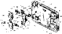
Fig. 5 is according to the exploded drawings door assembly of chip container of the present invention, that observe from the front side;
The exploded drawings that Fig. 6 is locking mechanism of the present invention, observe from rear side;
Fig. 7 is a stack-mounted door fwd front view of the present invention;
Fig. 8 is the viewgraph of cross-section that the latch portion in the locking mechanism of the present invention is in retrieving position;
Fig. 9 is the viewgraph of cross-section that the latch portion in the locking mechanism of the present invention is in extended position;
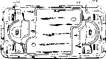
Figure 10 a is the front block diagram of the door of wafer carrier of the present invention;
Figure 10 b is the rear perspective view of the door of wafer carrier of the present invention.
The specific embodiment
The conveying assembly 30 that has the SMIG container 20 of bottom opening and have a front openings in Fig. 1 and 2 of the prior art shown in respectively is highly suitable for the present invention.Each sealable closure has container part 34 and synergistic door 36 respectively.SMIF container 20 also has wafer carrier 38 separately, and described wafer carrier 38 is the vehicles with H bar well known in the prior art (H-bar) shape, and the vehicle of this H of having strip is placed on the top surface 40 of door 36.
Each container part 34 and each closure have top side face 46, leading flank 48 and bottom side 50.In the SMIF container, bottom side 50 is openings, so that receive wafer 38 and door 36.
Door has inside side 52 and outside side 53, and its edge 55 comprises closure member 56, and closure member 56 has the inside 58 of opening, has wherein comprised locking mechanism 60, and Fig. 1 and 2 has described its subelement.Described locking mechanism comprises latch portion 62, and it can extend to the outside of groove 66, so that join the latch portion receptor 68 of the door bracket part 74 that is arranged in container part 34 to.With reference to accompanying drawing 3, wherein described the chip container of prior art, this chip container has handle 80, and described handle 80 can outwards be swung so that rotate.Described handle 80 is connected respectively to and is arranged in separately on the rotating cam member of a closure member.As shown in Figure 4, wherein described the chip container 90 that combines with the present invention, it comprises container part 92 usually, and synergistic door 94.Container part 92 has a plurality of wafer slots 100, so that insert or take out wafer W along horizontal surface basically.Constitute wafer slots 100 by wafer support 102.Usually, container part has open front 106, osed top top 108, and osed top left surface 110, osed top trailing flank 112 is at the bottom of osed top right flank 114 and the osed top 116.This container has the equipment connecting device (not shown) that is positioned at the osed top bottom usually.
Door can comprise protecgulum 160, and its shape is as flat board, and it is suitable for fixing, and for example adopts in the sequence number 08/904,660 disclosed elastic element to fix, and disclosed content in this article as a reference in above-mentioned file.Also comprise housing 162, it forms closure member 164.Two drive parts are made of artificial handle 170,172, and they extend by the hole in the protecgulum 160 174,176.Locking keyhole 180,182 provides automatic inlet, to the additional drives part that constitutes the key receptor.The hole 186,187 that latch portion 184,185 is passed in the edge 188 is stretched or is shunk.
With reference to Fig. 5~9, the closure member 164 of door has two cavitys 190,192, so that hold two locking mechanisms 200,202 that become different mirror images to be provided with respectively.In this embodiment, door has independent mechanism cover 203,204.In Fig. 5, first or left side locking mechanism 202 be decomposed and illustrate, second or right side locking mechanism 200 illustrate with the stack-mounted form.Fig. 6 represents the relative or medial side view of the left side locking mechanism that decomposes from Fig. 5.Each locking mechanism has drive part 205 usually, motion movable part 206 and latch portion 207.
In described preferred embodiment, each locking mechanism comprises slip drive part 210, and described slip drive part 210 comprises artificial handle 170,172 separately; Connecting bridge 218; A pair of connection connecting rod 224, its structure are tooth bar 224; And medium pore 225.Promote linkage and comprise the cam face 226 or second lift portion, its structure is the inclined-plane; Laterally steering groove 232,234; Central authorities' guide groove 236; And steady arm 240,242, the structure of steady arm is column.Promote link gear 220,222 and disposition of latch arm 250,252 synergies, described disposition of latch arm 250,252 comprises latch portion 184,185 and director element 258,259, and the structure of described director element is a guidepost, and guidepost extends from disposition of latch arm.Guidepost is positioned at laterally steering groove 232,234, and is subjected to the restriction of laterally steering groove 232,234.Disposition of latch arm 250,252 also has barrier element 268, and it has sturdy planform.Described barrier element 268 stretches out from the front 274 of disposition of latch arm 250,252.The rear side of disposition of latch arm 250,252 has first lift portion 276, its structure is as cam follower, cam follower has bevelled mating surfaces 277, and mating surfaces 277 is bonded with each other with second lift portion that promotes on the linkage, so that provide inside or outside motion for closed block.Cover element 203,204 keeps said elements in place, and the non-metal screw is fixed in the screw hole 282 in the post element 284 ideally.
The operational process of locking mechanism is similar to the locking mechanism shown in accompanying drawing 17 in the U.S. Patent application 08/891,645,18a, 19a, the 19b, 20,21, although wherein do not adopt rotary cam member, wherein disclosed content in this article as a reference.Employing has the sliding handle part of fixing lifting linkage, so that make linkage produce cross motion.In U.S. Patent application 08/891,645, disposition of latch arm also can with the cam member engages of rotating.In this embodiment, disposition of latch arm is fixed on and promotes in the linkage, and is moved by the structural limitations and the upper and lower of control disposition of latch arm of lid 203,204.
The separate part of door mechanism 100 can adopt suitable carbon fiber makrolon material manufacturing, so that quiet wearout characteristics is provided.The closure member of front panel and door adopts makrolon material to make.Blocking element can adopt the appropriate plastic material moulding, for example, adopts nylon or PEEK.
Claims (19)
1. resealable container (90) that is used to seal wafer, this container comprises:
A) be used for the container part (92) of holding chip, container part has the inside of opening, and the door bracket that constitutes the essentially rectangular of door opening, has the locking socket on the door bracket; With
B) can be arranged in the door (94) of door bracket, so that cover door opening (106), and the airtight container part, wafer is sealed in the container, described door has the front and comprises:
Outer seat part, its size are suitable for engaging with the door bracket (120) of essentially rectangular, and locking mechanism (164);
It is characterized in that described locking mechanism comprises:
Be exposed to the outer handle of described face in front of the door, described handle can be along cross motion;
Latch portion in order to extend into the locking socket, is perhaps return from the locking socket; With
Bonded assembly Motion Transmission part between described latch portion and handle is so that be converted into the cross motion of handle the stretching, extension of latch portion and return action;
Wherein, described Motion Transmission partly comprises gear and tooth bar.
2. according to the described chip container of claim 1, wherein door has left side and right side, and wherein locking mechanism is first locking mechanism, and chip container also comprises second locking mechanism, described first locking mechanism is positioned at the left side of door, and second locking mechanism is positioned at the right side of door.
3. chip container comprises:
A) be used for the container part of holding chip, container part has the inside of opening, constitutes the door bracket of the essentially rectangular of door opening, has the locking socket on the support of door;
B) can be arranged in the door of door bracket, so that cover door opening, door has front and outer seat part, and its size is suitable for engaging with the door bracket of essentially rectangular; And
Locking mechanism; Described locking mechanism comprises:
Latch portion is used for engaging with the locking socket;
First drive part is used to receive manual driven; Described first drive part is a handle that can laterally slide;
Second drive part is used to receive automatic driving; Described second drive part is a rotating blocking wedge receptor;
Between the described latch portion and first and second drive parts, be connected with the Motion Transmission part, so that the actuation movement of described handle or described blocking wedge receptor is converted into engaging between latch portion and the locking socket;
Described Motion Transmission is partly installed and is exposed on the front of door, and described door partly provides access for described Motion Transmission.
4. according to the described chip container of claim 3, wherein Motion Transmission partly comprises rack-and-pinion mechanism.
5. according to the described chip container of claim 5, it is characterized in that locking mechanism comprises:
Disposition of latch arm, it has two ends, one end has cam follower, and it engages with first cam guide, and the other end has latch portion, it extends to the opening in the outer seat part, promote linkage and have first lift portion, its between two ends, the structure of first cam guide, make latch portion stretch out, enter the locking socket along first direction with respect to door;
Promote linkage, it connects the sliding handle part, and can be together along cross motion, promote linkage and have synergistic second lift portion, described second lift portion and first lift portion engage, first lift portion and second lift portion are arranged in the mode of mutual overlapping, one of first lift portion and second lift portion have the inclined-plane, in first lift portion and second lift portion another has the surface that engages with the inclined-plane, the structure of second cam guide makes that promoting linkage moves with respect to locking and coupled system, diagonal cut miter joint partly is placed on the inclined-plane thus, when latch portion is positioned at the locking socket, make locking and coupled system move along the second direction that is substantially perpendicular to first direction.
6. sealable chip container comprises:
A) be used for the container part of holding chip, this container part has the inside of opening, constitutes the door bracket of the essentially rectangular of door opening before opening, has the locking socket on the door bracket;
B) door can be arranged in door bracket, so that cover door opening, and the airtight container part, door comprises:
Outer seat part, its size are suitable for engaging with the door bracket of essentially rectangular;
Locking mechanism;
Wherein, described locking mechanism comprises:
Be used to receive the extraneous drive part that drives, the drive part outside can feed, and rotatable;
Lock portion engages with the locking socket;
Miniature gears is connected on the drive part; With
Miniature gears and tooth bar engagement, and be connected to latch portion, the rotation of drive part makes latch portion move thus.
7. according to the described chip container of claim 6, wherein door has the front, and locking mechanism is exposed to the front of door.
8. according to the described chip container of claim 6, wherein drive part is first drive part, wherein locking mechanism also comprises second drive part, second drive part is limited transversely to move, second drive part connects tooth bar, therefore by the rotation of first drive part, perhaps the cross motion by second drive part can drive locking mechanism.
9. according to the described chip container of claim 8, wherein door has the front, and locking mechanism is exposed on the front of door.
10. according to the described chip container of claim 6, wherein door has front, left side and right side, and wherein locking mechanism is first locking mechanism, and chip container also comprises second locking mechanism, wherein first locking mechanism is positioned at the left side of door, and second locking mechanism is positioned at the right side of door.
11. a chip container comprises:
A) be used for the container part of holding chip, this container part has the inside of opening, constitutes the door bracket of door to the essentially rectangular of front openings, has the locking socket on the door bracket;
B) door can be arranged in door bracket, so that cover door opening, door has front and outer seat part, and its size is suitable for engaging with the door bracket of essentially rectangular;
Locking mechanism;
Wherein, described locking mechanism comprises:
The latch portion that cooperatively interacts with the locking socket;
The first pivotable drive part is used to receive the automatic driving of key;
Yun Dong second drive part transversely is so that by manual driven;
Between the latch portion and the first automatic drive part, and between the drive part of the latch portion and second cross motion, be connected with the Motion Transmission part, so that the actuation movement of drive part is converted to engaging of latch portion and locking socket;
Wherein, described Motion Transmission partly comprises rack-and-pinion.
12. according to the described chip container of claim 11, wherein locking mechanism is installed on the described front, and is not included in the closure member of door.
13. according to the described chip container of claim 11, wherein locking mechanism is first locking mechanism, chip container also comprises second locking mechanism, and second locking mechanism constitutes the mirror image setting with first breech-block basically.
14. according to the described chip container of claim 11, wherein Motion Transmission partly offers laterally outwards motion of latch portion, and forwards to motion.
15. a chip container, it comprises:
A) be used for the container part of holding chip, this container part has the inside of opening, constitutes the door bracket of the essentially rectangular of door opening, has the locking socket on the door bracket;
B) door can be arranged in door bracket, so that cover the opening of door, door has the inside (58) of opening, it is characterized in that, described door also comprises:
I) outer seat part, its size is suitable for engaging with the essentially rectangular door bracket, and when door was arranged in door bracket, the outer seat part of door had the opening corresponding to the locking socket;
Ii) sliding handle partly be limited and in closure member cross motion, described handle portion comprises and is exposed to a fwd handle;
Iii) disposition of latch arm has two ends, an end has cam follower, the described cam follower and first cam guide engage, another end has latch portion, said latch portion extends to the opening in the outer seat part, promote linkage and have first lift portion, described first lift portion is between two ends, and the structure of first cam guide makes latch portion stretch out at first direction with respect to door and enters the locking socket;
Iv) promote linkage and be connected to the sliding handle part, and together transversely direction motion, promote linkage and have synergistic second lift portion, described second lift portion engages with first lift portion, first lift portion and second lift portion are arranged with overlap mode, one of first lift portion and second lift portion have the inclined-plane, in first lift portion and second lift portion another has the surface that cooperates with the inclined-plane, the structure of second cam guide makes that promoting linkage moves with respect to locking and coupled system, therefore, when latch portion is arranged in the locking socket, diagonal cut miter joint partly is placed on the inclined-plane, makes locking and coupled system move along the second direction that is substantially perpendicular to first direction;
Be connected to the rack-and-pinion system of sliding handle part, can feed miniature gears from the outside of door, therefore by with the engaging of miniature gears, can the automatic guidance door.
16. a chip container comprises:
A) be used for the container part that along continuous straight runs is arranged holding chip, container part has the front of opening and at opening fwd, locking socket on container part; With
B) door can be located so that the opening front of closed container is characterized in that this door comprises:
I) have the disposition of latch arm of latch portion, latch portion is outwards extended towards the locking socket along first direction;
Ii) promote linkage, adjacent with locking and coupled system, and can move along the direction that is parallel to first direction, at least promote one of linkage and disposition of latch arm and have the inclined-plane, therefore, when another in promoting linkage and disposition of latch arm moved with respect to the inclined-plane, the inclined-plane made locking and coupled system move towards the second direction that is substantially perpendicular to first direction;
Iii) sliding handle partly is limited, and in closure member side travel, described handle portion comprises the handle that the face in front of the door of being exposed to is outer, and the connecting bridge that handle is connected to bont, therefore, can operated door by moving the outer handle that exposes, handle portion also comprises the linear gear that installs and fixes thereon;
The iv) rotary circular gear of door in the closure member, closure member and linear gear engagement can feed circular gear, so can carry out automatic guidance by opposite house outside the front of door.
17. according to the described chip container of claim 16, wherein the sliding handle part forms one with the lifting linkage.
18. according to the described chip container of claim 1, wherein locking mechanism is arranged in the cavity in the panel in front of the door, cavity is made of vertical side, and wherein door comprises that also mechanism cover, mechanism cover with periphery are arranged on the locking mechanism top, at least Zhou Bian a part and vertical side separate, therefore constitute a gap that feeding is provided, in order to cleaning and dry locking mechanism, and will the mechanism cover dismounting.
19. according to the described chip container of claim 3, wherein locking mechanism is arranged in the cavity in the panel in front of the door, cavity is made of vertical side and bottom surface, and wherein door also comprises the mechanism cover with periphery, therefore mechanism cover is arranged on the locking mechanism, and Zhou Bian a part and vertical side separate at least, constitutes a gap that feeding is provided, in order to cleaning and dry locking mechanism, and will not remove by mechanism cover.
Applications Claiming Priority (2)
| Application Number | Priority Date | Filing Date | Title |
|---|---|---|---|
| US14283199P | 1999-07-08 | 1999-07-08 | |
| US60/142,831 | 1999-07-08 |
Publications (2)
| Publication Number | Publication Date |
|---|---|
| CN1378515A CN1378515A (en) | 2002-11-06 |
| CN1169696C true CN1169696C (en) | 2004-10-06 |
Family
ID=22501466
Family Applications (1)
| Application Number | Title | Priority Date | Filing Date |
|---|---|---|---|
| CNB008115826A Expired - Lifetime CN1169696C (en) | 1999-07-08 | 2000-07-06 | Transport module with latching door |
Country Status (8)
| Country | Link |
|---|---|
| EP (1) | EP1218264A4 (en) |
| JP (1) | JP4549595B2 (en) |
| KR (1) | KR100747041B1 (en) |
| CN (1) | CN1169696C (en) |
| AU (1) | AU6341900A (en) |
| DE (1) | DE10084776T5 (en) |
| MY (1) | MY128807A (en) |
| WO (1) | WO2001004022A1 (en) |
Families Citing this family (8)
| Publication number | Priority date | Publication date | Assignee | Title |
|---|---|---|---|---|
| JP4052947B2 (en) * | 2001-05-17 | 2008-02-27 | 株式会社荏原製作所 | Substrate transfer container |
| US6749067B2 (en) * | 2002-01-16 | 2004-06-15 | Entegris, Inc. | Wafer carrier door with form fitting mechanism cover |
| US7325698B2 (en) | 2004-04-18 | 2008-02-05 | Entegris, Inc. | Wafer container door with particulate collecting structure |
| JP4573566B2 (en) | 2004-04-20 | 2010-11-04 | 信越ポリマー株式会社 | Storage container |
| CN1313331C (en) * | 2004-08-30 | 2007-05-02 | 财团法人工业技术研究院 | Clean container structure |
| JP4540529B2 (en) | 2005-04-18 | 2010-09-08 | 信越ポリマー株式会社 | Storage container |
| JP6544128B2 (en) * | 2015-08-07 | 2019-07-17 | シンフォニアテクノロジー株式会社 | Storage container lid and storage container |
| CN114628292B (en) * | 2022-05-16 | 2022-07-29 | 上海果纳半导体技术有限公司武汉分公司 | Wafer transmission box |
Family Cites Families (6)
| Publication number | Priority date | Publication date | Assignee | Title |
|---|---|---|---|---|
| US5173273A (en) * | 1990-10-11 | 1992-12-22 | Brewer Charles A | Cassette for dental instruments |
| US5915562A (en) * | 1996-07-12 | 1999-06-29 | Fluoroware, Inc. | Transport module with latching door |
| US5711427A (en) * | 1996-07-12 | 1998-01-27 | Fluoroware, Inc. | Wafer carrier with door |
| JP3476052B2 (en) * | 1997-09-01 | 2003-12-10 | 信越ポリマー株式会社 | Transport container |
| JP3722604B2 (en) * | 1997-11-13 | 2005-11-30 | 大日本スクリーン製造株式会社 | Substrate processing equipment |
| US6704998B1 (en) * | 1997-12-24 | 2004-03-16 | Asyst Technologies, Inc. | Port door removal and wafer handling robotic system |
-
2000
- 2000-07-06 JP JP2001509652A patent/JP4549595B2/en not_active Expired - Lifetime
- 2000-07-06 AU AU63419/00A patent/AU6341900A/en not_active Abandoned
- 2000-07-06 WO PCT/US2000/018511 patent/WO2001004022A1/en active Application Filing
- 2000-07-06 KR KR1020027000227A patent/KR100747041B1/en active IP Right Grant
- 2000-07-06 CN CNB008115826A patent/CN1169696C/en not_active Expired - Lifetime
- 2000-07-06 DE DE10084776T patent/DE10084776T5/en not_active Withdrawn
- 2000-07-06 EP EP00950296A patent/EP1218264A4/en not_active Withdrawn
- 2000-07-07 MY MYPI20003119A patent/MY128807A/en unknown
Also Published As
| Publication number | Publication date |
|---|---|
| MY128807A (en) | 2007-02-28 |
| DE10084776T5 (en) | 2005-12-01 |
| KR100747041B1 (en) | 2007-08-07 |
| WO2001004022A1 (en) | 2001-01-18 |
| WO2001004022B1 (en) | 2001-02-15 |
| EP1218264A1 (en) | 2002-07-03 |
| AU6341900A (en) | 2001-01-30 |
| JP2003504886A (en) | 2003-02-04 |
| KR20020063155A (en) | 2002-08-01 |
| JP4549595B2 (en) | 2010-09-22 |
| CN1378515A (en) | 2002-11-06 |
| EP1218264A4 (en) | 2007-09-26 |
Similar Documents
| Publication | Publication Date | Title |
|---|---|---|
| CN1161262C (en) | Transport module with latching door | |
| JP3998354B2 (en) | Transport container, lid opening / closing method and lid opening / closing device | |
| CN1135200C (en) | Wafer delivery device with door | |
| CN1106332C (en) | Wafer enclosure with door | |
| CN1308194C (en) | Transport case | |
| US5570987A (en) | Semiconductor wafer transport container | |
| CN1169696C (en) | Transport module with latching door | |
| US5988392A (en) | Shipping container | |
| US6105782A (en) | Storage container for precision substrates | |
| JPS61502994A (en) | Interface device between two sealed environments | |
| EP0472536A4 (en) | Sealable transportable container having improved latch mechanism | |
| TW200535069A (en) | Container | |
| US6945405B1 (en) | Transport module with latching door | |
| JP4049551B2 (en) | Storage container lid | |
| US6430877B1 (en) | Pod door alignment device | |
| US6536813B2 (en) | SMIF container latch mechanism | |
| US6772612B2 (en) | Door-in-door front opening unified pod | |
| JP4357013B2 (en) | Storage container lid open / close latch mechanism | |
| CN102753454B (en) | For the derailing switch of extreme ultraviolet photolithography box for photomask | |
| JP4508463B2 (en) | Manual open / close jig for container lid | |
| CN2830419Y (en) | Splitting metallic organic chemical gas-phase deposition reactor | |
| JP2010141222A (en) | Substrate storage container and lid attaching method thereof |
Legal Events
| Date | Code | Title | Description |
|---|---|---|---|
| C10 | Entry into substantive examination | ||
| SE01 | Entry into force of request for substantive examination | ||
| C06 | Publication | ||
| PB01 | Publication | ||
| C10 | Entry into substantive examination | ||
| SE01 | Entry into force of request for substantive examination | ||
| C14 | Grant of patent or utility model | ||
| GR01 | Patent grant | ||
| CX01 | Expiry of patent term |
Granted publication date: 20041006 |
|
| CX01 | Expiry of patent term |