CN1166564A - Shock absorber for opening or closing door - Google Patents
Shock absorber for opening or closing door Download PDFInfo
- Publication number
- CN1166564A CN1166564A CN97113143A CN97113143A CN1166564A CN 1166564 A CN1166564 A CN 1166564A CN 97113143 A CN97113143 A CN 97113143A CN 97113143 A CN97113143 A CN 97113143A CN 1166564 A CN1166564 A CN 1166564A
- Authority
- CN
- China
- Prior art keywords
- door
- arm
- state
- aforementioned
- pivot
- Prior art date
- Legal status (The legal status is an assumption and is not a legal conclusion. Google has not performed a legal analysis and makes no representation as to the accuracy of the status listed.)
- Granted
Links
Images


Classifications
-
- E—FIXED CONSTRUCTIONS
- E05—LOCKS; KEYS; WINDOW OR DOOR FITTINGS; SAFES
- E05D—HINGES OR SUSPENSION DEVICES FOR DOORS, WINDOWS OR WINGS
- E05D15/00—Suspension arrangements for wings
- E05D15/56—Suspension arrangements for wings with successive different movements
- E05D15/58—Suspension arrangements for wings with successive different movements with both swinging and sliding movements
- E05D15/582—Suspension arrangements for wings with successive different movements with both swinging and sliding movements with horizontal swinging axis
-
- E—FIXED CONSTRUCTIONS
- E05—LOCKS; KEYS; WINDOW OR DOOR FITTINGS; SAFES
- E05F—DEVICES FOR MOVING WINGS INTO OPEN OR CLOSED POSITION; CHECKS FOR WINGS; WING FITTINGS NOT OTHERWISE PROVIDED FOR, CONCERNED WITH THE FUNCTIONING OF THE WING
- E05F1/00—Closers or openers for wings, not otherwise provided for in this subclass
- E05F1/08—Closers or openers for wings, not otherwise provided for in this subclass spring-actuated, e.g. for horizontally sliding wings
- E05F1/10—Closers or openers for wings, not otherwise provided for in this subclass spring-actuated, e.g. for horizontally sliding wings for swinging wings, e.g. counterbalance
- E05F1/1041—Closers or openers for wings, not otherwise provided for in this subclass spring-actuated, e.g. for horizontally sliding wings for swinging wings, e.g. counterbalance with a coil spring perpendicular to the pivot axis
- E05F1/105—Closers or openers for wings, not otherwise provided for in this subclass spring-actuated, e.g. for horizontally sliding wings for swinging wings, e.g. counterbalance with a coil spring perpendicular to the pivot axis with a compression spring
- E05F1/1058—Closers or openers for wings, not otherwise provided for in this subclass spring-actuated, e.g. for horizontally sliding wings for swinging wings, e.g. counterbalance with a coil spring perpendicular to the pivot axis with a compression spring for counterbalancing
-
- E—FIXED CONSTRUCTIONS
- E05—LOCKS; KEYS; WINDOW OR DOOR FITTINGS; SAFES
- E05F—DEVICES FOR MOVING WINGS INTO OPEN OR CLOSED POSITION; CHECKS FOR WINGS; WING FITTINGS NOT OTHERWISE PROVIDED FOR, CONCERNED WITH THE FUNCTIONING OF THE WING
- E05F1/00—Closers or openers for wings, not otherwise provided for in this subclass
- E05F1/08—Closers or openers for wings, not otherwise provided for in this subclass spring-actuated, e.g. for horizontally sliding wings
- E05F1/10—Closers or openers for wings, not otherwise provided for in this subclass spring-actuated, e.g. for horizontally sliding wings for swinging wings, e.g. counterbalance
- E05F1/12—Mechanisms in the shape of hinges or pivots, operated by springs
- E05F1/1246—Mechanisms in the shape of hinges or pivots, operated by springs with a coil spring perpendicular to the pivot axis
- E05F1/1269—Mechanisms in the shape of hinges or pivots, operated by springs with a coil spring perpendicular to the pivot axis with a traction spring
- E05F1/1276—Mechanisms in the shape of hinges or pivots, operated by springs with a coil spring perpendicular to the pivot axis with a traction spring for counterbalancing
-
- E—FIXED CONSTRUCTIONS
- E05—LOCKS; KEYS; WINDOW OR DOOR FITTINGS; SAFES
- E05D—HINGES OR SUSPENSION DEVICES FOR DOORS, WINDOWS OR WINGS
- E05D11/00—Additional features or accessories of hinges
- E05D11/08—Friction devices between relatively-movable hinge parts
- E05D11/087—Friction devices between relatively-movable hinge parts with substantially axial friction, e.g. friction disks
-
- E—FIXED CONSTRUCTIONS
- E05—LOCKS; KEYS; WINDOW OR DOOR FITTINGS; SAFES
- E05F—DEVICES FOR MOVING WINGS INTO OPEN OR CLOSED POSITION; CHECKS FOR WINGS; WING FITTINGS NOT OTHERWISE PROVIDED FOR, CONCERNED WITH THE FUNCTIONING OF THE WING
- E05F3/00—Closers or openers with braking devices, e.g. checks; Construction of pneumatic or liquid braking devices
- E05F3/14—Closers or openers with braking devices, e.g. checks; Construction of pneumatic or liquid braking devices with fluid brakes of the rotary type
-
- E—FIXED CONSTRUCTIONS
- E05—LOCKS; KEYS; WINDOW OR DOOR FITTINGS; SAFES
- E05F—DEVICES FOR MOVING WINGS INTO OPEN OR CLOSED POSITION; CHECKS FOR WINGS; WING FITTINGS NOT OTHERWISE PROVIDED FOR, CONCERNED WITH THE FUNCTIONING OF THE WING
- E05F3/00—Closers or openers with braking devices, e.g. checks; Construction of pneumatic or liquid braking devices
- E05F3/16—Closers or openers with braking devices, e.g. checks; Construction of pneumatic or liquid braking devices with friction brakes
-
- E—FIXED CONSTRUCTIONS
- E05—LOCKS; KEYS; WINDOW OR DOOR FITTINGS; SAFES
- E05Y—INDEXING SCHEME RELATING TO HINGES OR OTHER SUSPENSION DEVICES FOR DOORS, WINDOWS OR WINGS AND DEVICES FOR MOVING WINGS INTO OPEN OR CLOSED POSITION, CHECKS FOR WINGS AND WING FITTINGS NOT OTHERWISE PROVIDED FOR, CONCERNED WITH THE FUNCTIONING OF THE WING
- E05Y2201/00—Constructional elements; Accessories therefore
- E05Y2201/20—Brakes; Disengaging means, e.g. clutches; Holders, e.g. locks; Stops; Accessories therefore
- E05Y2201/21—Brakes
-
- E—FIXED CONSTRUCTIONS
- E05—LOCKS; KEYS; WINDOW OR DOOR FITTINGS; SAFES
- E05Y—INDEXING SCHEME RELATING TO HINGES OR OTHER SUSPENSION DEVICES FOR DOORS, WINDOWS OR WINGS AND DEVICES FOR MOVING WINGS INTO OPEN OR CLOSED POSITION, CHECKS FOR WINGS AND WING FITTINGS NOT OTHERWISE PROVIDED FOR, CONCERNED WITH THE FUNCTIONING OF THE WING
- E05Y2201/00—Constructional elements; Accessories therefore
- E05Y2201/20—Brakes; Disengaging means, e.g. clutches; Holders, e.g. locks; Stops; Accessories therefore
- E05Y2201/252—Brakes; Disengaging means, e.g. clutches; Holders, e.g. locks; Stops; Accessories therefore characterised by type of friction
- E05Y2201/254—Fluid or viscous friction
-
- E—FIXED CONSTRUCTIONS
- E05—LOCKS; KEYS; WINDOW OR DOOR FITTINGS; SAFES
- E05Y—INDEXING SCHEME RELATING TO HINGES OR OTHER SUSPENSION DEVICES FOR DOORS, WINDOWS OR WINGS AND DEVICES FOR MOVING WINGS INTO OPEN OR CLOSED POSITION, CHECKS FOR WINGS AND WING FITTINGS NOT OTHERWISE PROVIDED FOR, CONCERNED WITH THE FUNCTIONING OF THE WING
- E05Y2201/00—Constructional elements; Accessories therefore
- E05Y2201/20—Brakes; Disengaging means, e.g. clutches; Holders, e.g. locks; Stops; Accessories therefore
- E05Y2201/262—Brakes; Disengaging means, e.g. clutches; Holders, e.g. locks; Stops; Accessories therefore characterised by type of motion
- E05Y2201/266—Brakes; Disengaging means, e.g. clutches; Holders, e.g. locks; Stops; Accessories therefore characterised by type of motion rotary
-
- E—FIXED CONSTRUCTIONS
- E05—LOCKS; KEYS; WINDOW OR DOOR FITTINGS; SAFES
- E05Y—INDEXING SCHEME RELATING TO HINGES OR OTHER SUSPENSION DEVICES FOR DOORS, WINDOWS OR WINGS AND DEVICES FOR MOVING WINGS INTO OPEN OR CLOSED POSITION, CHECKS FOR WINGS AND WING FITTINGS NOT OTHERWISE PROVIDED FOR, CONCERNED WITH THE FUNCTIONING OF THE WING
- E05Y2800/00—Details, accessories and auxiliary operations not otherwise provided for
- E05Y2800/15—Applicability
- E05Y2800/17—Universally applicable
- E05Y2800/172—Universally applicable on different wing or frame locations
-
- E—FIXED CONSTRUCTIONS
- E05—LOCKS; KEYS; WINDOW OR DOOR FITTINGS; SAFES
- E05Y—INDEXING SCHEME RELATING TO HINGES OR OTHER SUSPENSION DEVICES FOR DOORS, WINDOWS OR WINGS AND DEVICES FOR MOVING WINGS INTO OPEN OR CLOSED POSITION, CHECKS FOR WINGS AND WING FITTINGS NOT OTHERWISE PROVIDED FOR, CONCERNED WITH THE FUNCTIONING OF THE WING
- E05Y2900/00—Application of doors, windows, wings or fittings thereof
- E05Y2900/20—Application of doors, windows, wings or fittings thereof for furnitures, e.g. cabinets
Abstract
A door which use shock absorber when open or close. A mounting case is mounted on the side plate inner wall of a door mounting body, and a rotating arm pivotally fixed thereto by an arm shaft is pivotally fixed to the washer of a door. In door closing, a spring holding traveling body within the mounting case is moved down by a compression spring, whereby a rotating force in an arrowed direction is energized to the rotating arm by a shaft pin a through a link arm pivotally fixed by the shaft pin to hold the door closed state. When the door is opened, the shaft pin is transferred to the left side of the axially vertical line, the rotating arm receives a rotating force in the anti- arrowed direction by the compression spring to support the door opening operation, and in door closing, the braking force is worked to ensure a gentle closing motion.
Description
The present invention relates to a kind of various doors that the suitable position of the door fixing body of formations such as Men Zaiyong housing articulated with hinge or slide hinge that are used for, door after opening can be placed in the suspension type door on the fixing body top board, the bottom-open type door, last open type door, last open-type door, the swing cover type door and described later on open and push ccontaining formula door, only need be installed in a fixing body side plate inwall, the top board inwall, and can use between plate inner wall etc. and the door, and can make the door on-off action can be easy, the shock absorber for opening or closing door that carries out light and slowly.
A kind of traditional device for opening/closing door is arranged as shown in figure 18, door a is hidden in the inboard, below (Japanese Utility Model bulletin 1985-18528 number) of the inside of fixing body b, its top board c.
Yet, in above-mentioned conventional example, to on door a and door fixing body b, articulate the support bar d and the quarter butt e of the usefulness that door a is opened and closed by the above-below direction rotation, set up spring f, establish the slide mechanism that constitutes by slide rail g and door guide roller h in also wanting, make the installation of an a and position adjustments operation that door is installed back door a very difficult, and, make a spatial accommodation of fixing body b inside become narrow because of door a is hidden in the inside of fixing body b.
And under the open mode of door a, support bar d and spring f expose, so outward appearance is not good, and when carrying out opening and closing operations, exists accidents such as finger and sandwich danger between spring f and this spring f and the support bar d.
Problem in view of above-mentioned conventional art, in technical scheme 1 of the present invention, rotating upward on the suspension type door of opening by a bottom of door, in the time of on the top board that will be placed in door a fixing body, the side plate inwall that housing is fixed in a fixing body is installed, thus, articulate rotate cursor front end that stretches out freely and the pad that is installed on the door at the arm axle place, can constitute this suspension type door by this simple operation, this is the 1st purpose of this programme.
And then, by connecting pivot pin, the bottom of the linking arm that the spring-loaded moving body afterburning downwards be compressed spring in above-mentioned installation housing articulated articulates with the rotation base portion because of the rotating cursor of arm axle, thereby can apply in good time cursor, suitable rotatory force, make and to keep this closed condition at closing time, and when carrying out opening door operation, carry out opening door operation by the elastic force that utilizes aforementioned compression spring in good time, and can easily be placed in door on the top board with less power, can not take place simultaneously because of compression spring etc. expose influence attractive in appearance, or situation about sandwiching at the opening and closing operations time finger that carries out door etc., this is the 2nd purpose of this programme.
And then again on above-mentioned installation housing, by connecting pivot pin, the upper end of the linking arm that the spring-loaded moving body afterburning upward be compressed spring in above-mentioned housing articulated articulates with the rotation base portion because of the rotating cursor of arm axle, thereby can apply suitably in good time rotatory force to cursor, make and to keep this closed condition by the aforementioned pivot arm that connects at closing time, and when carrying out opening door operation, make the action of opening the door be able to light and slow carrying out by the brake force of utilizing aforementioned compression spring, and can not take place because of compression spring etc. expose influence attractive in appearance, or situation about sandwiching at the switching operation time finger that carries out door etc., this is the 2nd purpose of this programme.
And then on above-mentioned installation housing, by connecting pivot pin, articulating with lateral ends that in above-mentioned housing, is compressed the linking arm that spring articulates to the spring-loaded moving body of horizontal reinforcing and rotation base portion because of the rotating cursor of arm axle, thereby can apply in good time cursor, suitable rotatory force, make and to keep this closed condition by the aforementioned pivot arm that connects at closing time, and when carrying out opening door operation, by utilizing the elastic force of aforementioned compression spring, can finish the action of opening the door with less power, self-evident, identical with scheme 5, it is specious, can not point the danger that sandwiches, this is the 2nd purpose of this programme.
And then, scheme 9 is being installed on the housing, by connecting pivot pin, the bottom of the linking arm that the spring-loaded moving body afterburning downwards be compressed spring in above-mentioned housing articulated articulates with the rotation base portion because of the rotating cursor of arm axle, thereby can apply in good time, suitable rotatory force to cursor, make and to keep this closed condition by the aforementioned pivot arm that connects at closing time, and when carrying out opening door operation, after making door open to a certain degree, by utilizing the elastic force of aforementioned compression spring, can finish the action of opening the door with less power.Keep linear state up to cursor and company's pivot arm, after opening fully, this door opening state can be kept by the compression spring, self-evident, this programme does not have operational danger with aforesaid the same, specious, and this is the 2nd purpose of this programme.
And not directly to be installed on the side plate inwall a housing is installed in this occasion, but traversing carriage freely is installed by the slide rail of being located at this side plate inwall, on this carriage, fix above-mentioned installation housing, simultaneously between this carriage and door, not with simple hinge, but connect pivot with slide hinge, and with aforesaid the same, articulate with the cursor that stretches out freely in the rotation of arm axle place freely connecting the rotation of pivot arm, and this connect the pivot arm with the door pad connect pivot, constitute to open on above-mentioned by this simple operation and push ccontaining formula door, this is the 1st purpose of this programme.
And then, the same with scheme 9, can apply in good time, suitable rotatory force to cursor, make can keep this closed condition by connecting the pivot arm at closing time, and when carrying out opening door operation, after door is opened slightly, utilize aforementioned compression spring, can finish the action of opening the door with less power.And then, after opening fully,, can finish the action of opening the door with less power by the compression spring.And the door opening state of the state of being up to the standard can be kept by compression spring and slide hinge, can finish aforesaidly then more reposefully with the action that pushes in the Men Xiangmen fixing body by carriage moving on slide rail, this is the 2nd purpose of this programme.
To achieve these goals, technical scheme 1 of the present invention is a kind of shock absorber for opening or closing door, it is characterized in that, on the door fixing body of suspension type door, is provided with the installation housing that is fixed in its side plate inwall; Lifting is contained in wherein spring-loaded moving body freely and to be compressed the afterburning state of spring downwards in this installation housing; The upper end is by pivot pin and with the rotation state freely and the linking arm of this spring-loaded moving body pivot joint; Rotate freely by arm axle in aforementioned installation lower part of frame, by the rotation base portion that around this arm axle, the bottom of above-mentioned linking arm is articulated by connecting pivot pin and from this rotations base portion stretch out, leading section opens and closes with pin by door and be installed on the cursor that the arm of the pad pivot joint on the suspension type door constitutes; With the pivoting point position between the above-mentioned rotation base portion that connects linking arm that pivot pin forms and cursor under the closed condition of suspension type door, more lean on door one side than the axle center vertical line that connects aforementioned pivot pin and arm axle, in the initial stage way of opening the door, transfer on the vertical line of above-mentioned axle center, rotating mounting from follow-up door opening state to door till on the top board of door fixing body, transferring to a side opposite of axle center vertical line with door.
This technical scheme that is 14 is a kind of shock absorber for opening or closing door, it is characterized in that, with slide hinge the upper end inner face of the perpendicular door that is loaded on a fixing body peristome inboard with laterally move by the slide rail of being located at the side plate inwall freely carriage articulate and can push the Men Xiangmen fixing body depths of opening and being the level of state and ccontaining freely on open and push on the ccontaining formula door, be provided with the installation housing that is fixed in above-mentioned carriage; With the state that rotates freely upper end and lifting moving in this installation housing are contained in the linking arm that spring-loaded moving body wherein articulates freely and to be compressed the afterburning state of spring downwards by pivot pin; Rotate freely by arm axle in aforementioned installation lower part of frame, and the cursor that constitutes by rotation base portion that around this arm axle, by connecting pivot pin the bottom of above-mentioned linking arm is articulated and the arm that stretches out from this rotation base portion; Articulate with the front end of above-mentioned arm by the pivot backing pin, with arm keep freely linear state, simultaneously to peristome one side of door fixing body rotate bending freely and leading section open and close by door with pin and the company's pivot arm that is installed in the pad pivot joint of opening on the door that pushes ccontaining formula door; When between arm and company's pivot arm, being bending state with the pivoting point position between the above-mentioned rotation base portion that connects linking arm that pivot pin forms and cursor, more lean on door one side than the axle center vertical line that connects aforementioned pivot pin and arm axle, be under the door opening state as the A-stage of opening the door with door that carriage articulates through slide hinge, transfer on the vertical line of above-mentioned axle center, from follow-up door opening state to arm with connect the pivot arm and keep linear state, formation is opened the door and is finished till the state, the elongation of compression spring, aforementioned pivoting point position transfer is to more leaning on a side opposite with door than aforementioned axle center vertical line, and aforementioned arm axle is located at and is installed on the housing, and with the closing direction of opposite house or open, closing the axis of rotation that all directions have a damper mechanism of the brake force that forms with viscous fluid connects.
It below is simple declaration to accompanying drawing
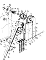
Fig. 1 is that at closing time the master of local excision looks skeleton diagram in the user mode of shock absorber for opening or closing door of expression suspension type door of the present invention.
Fig. 2 is that the master of local excision of the follow-up A-stage of opening the door looks skeleton diagram in the user mode of shock absorber for opening or closing door of the above-mentioned suspension type door of expression.
Fig. 3 is that the master of local excision of the follow-up later stage state that opens the door looks skeleton diagram in the user mode of shock absorber for opening or closing door of the above-mentioned suspension type door of expression.
Fig. 4 is that the master of local excision who in the user mode of shock absorber for opening or closing door of the above-mentioned suspension type door of expression door is placed in the top board state looks skeleton diagram.
Fig. 5 is the exploded perspective key diagram of expression above-mentioned shock absorber for opening or closing door one embodiment of the present invention.
Fig. 6 represents the shock absorber for opening or closing door that technical solution of the present invention 5 and scheme 6 relate to is used for the bottom-open type door, (A) be at closing time, (B) be that the master of local excision when opening the door looks skeleton diagram.
Fig. 7 is the exploded perspective view of shock absorber for opening or closing door one embodiment of expression technical solution of the present invention below 5.
Fig. 8 represents the shock absorber for opening or closing door that technical solution of the present invention 7 and scheme 8 relate to is used for the open type door, (A) be at closing time, (B) be that the master of local excision when opening the door looks skeleton diagram.
Fig. 9 represents the shock absorber for opening or closing door that technical solution of the present invention 9 and scheme 10 relate to is used for open-type door, is that at closing time the master of local excision looks skeleton diagram.
The master of local excision in the A-stage of opening the door when Figure 10 represents that the shock absorber for opening or closing door of Fig. 9 is used for open-type door looks skeleton diagram.
When representing that the shock absorber for opening or closing door of Fig. 9 is used for open-type door, Figure 11 looks skeleton diagram the finish master of local excision of state of opening the door.
The master of closed condition local excision when Figure 12 represents that the shock absorber for opening or closing door of technical solution of the present invention 11 and scheme 12 is used for the swing cover type door looks skeleton diagram.
The master of local excision on the way of opening the door when Figure 13 represents that the shock absorber for opening or closing door of Figure 12 is used for the swing cover type door looks skeleton diagram.
When representing that the shock absorber for opening or closing door of Figure 12 is used for the swing cover type door, Figure 14 looks skeleton diagram the finish master of local excision of state of opening the door.
Figure 15 represents the master of closed condition local excision that the shock absorber for opening or closing door of technical solution of the present invention 13 and scheme 14 is used for opening when pushing ccontaining formula door is looked skeleton diagram
Figure 16 represents the shock absorber for opening or closing door of Figure 15 is used for opening when pushing ccontaining formula door the finish master of local excision of state of opening the door and looks skeleton diagram.
Figure 17 is the summary left view of Figure 16.
Figure 18 is the longitudinal section of traditional suspension type door one example of expression.
To Fig. 5 the present invention is described below in conjunction with Fig. 1, technical scheme 1 and scheme 2 are constructed as follows.That is, on the suspension type door D as door, at the leading edge 1c of the top board 1b of door fixing body 1a, the end of hinge 1d is installed, its other end is fixedly arranged on the inner tracks 1g of the slide rail 1f that imbeds a 1e back side.Thereby,, be that rotation is opened at the center with the pivot backing pin 1h of hinge 1d and can make a 1e by the bottom of door 1e is upwards carried forward, do above-mentioned open rotation after, this 1e is pushed, make external orbital 1i relative interior track 1g and slide, thereby a 1e is placed on the top board 1b.
The present invention relates on above-mentioned suspension type door D, make the above-mentioned opening action of a 1e and the shock absorber for opening or closing door that closing motion is steadily carried out, as Fig. 1 and shown in Figure 5, on above-mentioned door fixing body 1a, top one side at the peristome 1k of its side plate inwall 1j is provided with the installation housing of fixing with screw 2 grades 3, and in this installations housing 3 lifting freely and with by the compression spring 4 of requirement downwards the state of reinforcing be contained in wherein spring-loaded moving body 5.
Example as above-mentioned installation housing 3, as shown in Figure 5, constitute by the enhancing cover plate 3a of the 1j that is installed on aforementioned side plate inwall and the installation enclosure body 3b that is embedded in wherein, in Fig. 5,3c is for used for screw 2 shown in Figure 1, be arranged in the installing hole that strengthens on the cover plate 3a, 3d is arranged in the through hole that strengthens cover plate 3a top plate portion 3e, 3f is the installation screw that is arranged in the top end 3g that enclosure body 3b is installed, being installed, enclosure body 3b is being embedded under the state that strengthens cover plate 3a, from through hole 3d not shown screw is carried out screw thread with installation screw 3f and combine, housing 3 is installed thereby constitute integratedly.
In Fig. 5,3h represents from the two side ends edge of the above-mentioned top plate portion 3e that strengthens cover plate 3a the side plate that housing backplate 3i erects to be installed, 3j represents the inboard board erect along housing front panel 3k from the two side ends of the above-mentioned top end 3g that enclosure body 3b is installed, and so just formation can supply aforementioned spring-loaded body 5 liftings embedded spatial accommodation 3m freely on installation enclosure body 3b.
Again, spring arresting lever 3q connected be fixed on a pair of through hole 3n that is located at above-mentioned side plate 3h and be arranged in the inboard through hole 3p of interior plate 3j, the upper end of compression spring 4 described later is compressed with it.
Below describe with regard to aforesaid spring-loaded moving body 5, in the embodiment of Fig. 5, by front side wall 5a, back face wall 5b and about side walls 5c form the box-shaped of upper end open, and by a pair of side walls 5c and 3 space 5e that the ammunition feed spring places of partition wall 5d formation in parallel, 3 compression springs 4 that wherein hold as previously mentioned, its top and spring arresting lever 3q butt, its underpart pushes the compression rod 5f on the side walls 5c that laterally is installed in spring-loaded moving body 5.
Thereby this spring-loaded moving body 5 slides on the internal face of the inboard board 3j that housing 3 is installed by its side walls 5c in spatial accommodation 3m, upward (compression spring 4 by compression) and below (this compression spring 4 extends) lifting freely.
The embodiment of Fig. 5 relates to technical scheme 3 of the present invention and scheme 4, internal face at above-mentioned inboard board 3j vertically is provided with lifting guiding groove 3r, the side walls 5c that makes spring-loaded moving body 5 cooperates with it and makes lifting moving, thereby, when spring-loaded moving body 5 descends, meeting and the stopper portions 3s butt that is formed at above-mentioned lifting guiding groove 3r lower end limit the decline degree of this spring-loaded moving body 5 with this.That is, under this state, the recuperability of compression spring 4 can not have been transmitted the next stage member of giving described later.
The present invention is also articulating the upper end of linking arm 6 with rotation state freely by pivot pin 6a on above-mentioned spring-loaded moving body 5, and rotate freely by arm axle 7a in the bottom that housing 3 is installed, and around this arm axle 7a, the rotation base portion 7b of the bottom of above-mentioned linking arm 6 and cursor 7 is articulated by connecting pivot pin 6b.The leading section of the arm 7c of the cursor 7 that stretches out from this rotation base portion 7b opens and closes with pin 7d and pad 8 pivot joints that are installed on the 1e by door.
Here, because of above-mentioned linking arm 6 and spring-loaded moving body 5 being articulated by pivot pin 6a, so in the embodiment of Fig. 5, lower center portion at this spring-loaded moving body 5, not merely to wear through hole, but the state gone up with lower ending opening of wall 5a and back face wall 5b wears the longitudinal trough 5g that technical scheme 3 and 4 relates in front, and pivot pin 6a is chimeric with lifting state and this longitudinal trough 5g freely.
In addition, about the relation between aforesaid cursor 7 and arm axle 7a, as shown in the figure, for the rotation that makes cursor 7 passes to arm axle 7a, arm axle 7a goes up the stop protuberance 7f that forms and cooperates with the stop recess 7h that is arranged in the axis hole 7g that rotates base portion 7b, in the structure of technical scheme 2 and scheme 4, the coaxial connection of turning cylinder 9a of above-mentioned arm axle 7a and the damper mechanism 9 of the bottom of being located at installation housing 3
Thereby in illustrated embodiment, as described later, because cursor 7 rotates, all directions performance cushioning effect be opened, be closed to the brake force that is caused by not shown viscous fluids in the damper mechanism 9 can or at the closing direction of door 1e.
Damper mechanism shown in Figure 59 self is identical with conventional apparatus, 9b is located at the damper bearing portion that enclosure body 3b bottom is installed among the figure, 9c is chimeric and rotation movable plate freely with turning cylinder 9a, 9d is adjacent with movable plate and stops the fixed disk that rotates, 9e and 9f are O shape rings, 9g is the lid of damper mechanism 9, with not shown check screw, and through the stop hole 3t that strengthens cover plate 3a and fixed.
In above-mentioned structure, importantly when the bottom of linking arm 6 is articulated in the rotation base portion 7b of cursor 7 by connecting pivot pin 6b, select the position of this pivoting point P.For this reason, at first when closed condition shown in Figure 1, make the axle center vertical line L of relative aforementioned pivot pin 6a of connection of above-mentioned pivoting point P and arm axle 7a and be positioned at a side of depending on door 1e.
As a result, as shown in Figure 1, the compression spring 4 of the shock absorber for opening or closing door of the suspension type door of technical scheme 1 is compressive state, and because its recuperability produces downward power to linking arm 6.Thereby, through pivoting point P, in the rotatory force of the rotation base portion 7b of cursor 7 generation to arrow R1 direction, its result, arm 7c rotates to arrow R2 direction, and therefore a door 1e keeps this closed condition, can not meet accident and open the door.
Then, in case forwards upwards mention and the action of opening the door the bottom at following door 1 of the closed condition of Fig. 1, as shown in Figure 2, pivoting point P turns left, finally arrive on the vertical line L of above-mentioned axle center, the position of the pivoting point P in this initial stage way of opening the door becomes the point of a key.Continue then to open the door, as shown in Figure 3, form follow-up door opening state, at this moment pivoting point P rotates relative to aforementioned axle center vertical line L and transfers to the opposite side with door 1e, so making, the recuperability of compression spring 4 rotates base portion 7b to the arrow R3 direction rotation opposite with aforementioned arrows R1, cursor 7 is shown in arrow R4, and the rotation of clamshell doors direction gives power-assisted.Utilize the recuperability of compression spring 4, can carry out opening door operation, and can be placed in door 1e rotation on the top board 1b with less power.
When will be being placed in a door 1e on the top board 1b when closing, can forwards leave behind this 1e, even let go then, door 1e also can make closing motion because of its gravity, at this moment, owing to be will compress spring 4 gradually to compress from its elongation state, so cushioning effect that elastic force caused light and slow carry out of action that close the door because of compression spring 4, and reset into the closed condition of Fig. 1, and this state is kept because of the recuperability of compression spring 4.
Consequently, door 1e becomes complete free state, so can go into a door 1e to top board 1b one thruster from the state of Fig. 3, at this moment scheme 3 as previously mentioned owing on spring-loaded moving body 5, wear longitudinal trough 5g, so under the state of Fig. 3, though pivot pin 6a still is positioned at the last ora terminalis of longitudinal trough 5g, by the operation that opens Door by Hand of back, this pivot pin 6a descends in longitudinal trough 5g gradually, so as shown in Figure 4, can push door 1e always and be placed on the top board 1b.Certainly, at this moment be to become possibility because of external orbital 1i slides to make to push on inner tracks 1g.
The shock absorber for opening or closing door that is used for the bottom-open type door about technical scheme 5, below the embodiment by Fig. 6 describes in detail, on bottom-open type door D1, door 1e combines with the base plate edge of opening 1n screw thread of peristome 1k one side of the base plate 1m of door fixing body 1a through hinge 1d, thereby this 1e can be in the fastening position from the erectility shown in Fig. 6 (A), roughly is in line between the opening position of laterally lying down of state switching freely to door 1e shown in Fig. 6 (B) and base plate 1m.
The invention of scheme 5 is on above-mentioned bottom-open type door D1, be provided with the damper that the on-off action that can make a 1e steadily carries out with supporting functions, as shown in Figure 6 and Figure 7, and as previously mentioned, on above-mentioned door fixing body 1a, in bottom one side of the peristome 1k of its side panel inwall 1j, be provided with fixing installation housing 3 such as screw 2 grades, and in this installations housing 3 lifting freely and with by the compression spring 4 of required radical upward the state of reinforcing be contained in wherein spring-loaded moving body 5.
As the example of above-mentioned installation housing 3, as shown in Figure 7, has identical construction with Fig. 5, all identical components all are marked with same-sign, different is, with Fig. 5 lifting guiding groove 3r and the corresponding position of stopper portions 3s in the housing 3 is not installed among Fig. 7, and has following additional structure.
That is, the same with Fig. 5, in Fig. 7, the rotation base portion 7b of the upper end of linking arm 6 and cursor 7 connects pivot, and moreover, the leading section of the arm 7c of the cursor 7 that stretches out from this rotation base portion 7b also articulates by pivot backing pin 7i and with the base end part 10a that connects pivot arm 10.
In order to make the above-mentioned arm 7c that connects pivot arm 10 and cursor 7 keep linear state, the base end part 10a that connects pivot arm 10 is inserted arm 7c go up the gap 7e that forms, and the 7j of folded edge portion that connects pivot arm 10 and arm 7c withstands, so can keep above-mentioned linear state, and prevention is further rotated, and by round about, be the rotation of arrow R direction among Fig. 7, can be folding in the 7e of gap with connecting pivot arm 10.And this leading section 10b that connects pivot arm 10 opens and closes with pin 10c pad 8 pivot joints with the door 1e back side of the bottom-open type door D1 that is installed in Fig. 6 with screw etc. by door.
Below with Fig. 6 above-mentioned structure is described in more detail, in the closed condition shown in Fig. 6 (A), make position by the pivoting point P between the rotation base portion 7b that connects linking arm 6 that pivot pin 6b forms and cursor 7, arm 7c with connect pivot arm 10 be bending state and compression spring 4 under the prerequisite of elongation state, more lean on a side than connecting the axle center vertical line L1 of pivot pin 6a with arm axle 7a.
Promptly, compression spring 4 upwards pushes away spring-loaded moving body 5 in housing 3 is installed, the company's of making pivot arm 10 is the side rotation bending by door 1e of middle mind-set arm 7c with pivot backing pin 7i, and connect the side of leaning on that at this moment pivot pin 6b is positioned at axle center warp L1, so the recuperability of passing through compression spring 4 is to rotating the rotatory force of base portion 7b transmission to arrow R1 direction, the result is that process connects 10 doors of pivot arm 1e to peristome 1k one layback, thereby guarantees closed condition.
Then, if the top of the door 1e of closed condition is forwards pulled down, making with hinge 1d is the center of rotation action of opening the door, then pass through pad 8 and traction company pivot arm 10, make at arm 7c and connect the bending angle θ 1 that forms between the pivot arm 10 and increase gradually, linking arm 6 moves down spring-loaded moving body 5, thereby compression spring 4 is compressed, so opening action along with door 1e, the recuperability of compression spring increases, and makes a 1e limit be subjected to the brake force limit to opening the door of Fig. 6 (B) the state down maneuver that rotates that finishes.
Open the door when finishing state becoming, aforesaid bending angle θ 1 becomes 180 °, the 7j of the folded edge portion butt that connects pivot arm 10 and arm 7c this moment makes arm 7c therefrom and connects pivot arm 10 and keep linear states, until a base plate 1m and the door 1e of the door fixing body 1a state that is in line.At this moment, in the present invention, be aforementioned pivoting point P to be rotated descend, its position is roughly transferred on the aforementioned axle center vertical line L1.Thereby, opening the door at this finishes under the state, and compression spring 4 is fully compressed, and the rotatory force that the recuperability of compression spring 4 produces is through connecting pivot pin 6b and transmitting to rotating base portion 7b, so door 1e can not be subjected to excessive power, can keep the door opening state of approximate horizontal.
Below the damper that is used for the bottom-open type door that relates to regard to technical scheme 6 describe, this scheme 6 is in the structure of such scheme 5, arm axle 7a is set installing on the housing 3 as shown in Figure 5, and the axis of rotation 9a that all directions have a damper mechanism 9 of the brake force that viscous fluid causes that opens or open, closes of opposite house 1f is connected with above-mentioned arm axle 7a.
At this moment, as previously mentioned, if only the time make mechanism's 9 performance brake force in the action of opening the door by not shown mono-directional overrun clutch, the then more light and slow and action of opening the door reposefully of occasion by the comparable scheme 5 of this brake force that under door opening state, acts on.
Below the damper of the last open type door usefulness that relates to regard to technical scheme 7 describe in detail, last open type door D2 as shown in Figure 8, the peristome 1k upward opening of door fixing body 1a, with relative another side plate 1q and another side plate is constituted a fixing body 1a by side plate 1p, with hinge 1d door 1e is opened and closed and combine with the upward opening edge 1r screw thread of another side plate 1q freely.
The shock absorber for opening or closing door that essential structure and aforementioned schemes 5 are roughly the same is different with the occasion of Fig. 6, be on the side plate inwall 1j of aforementioned pair of side plates, near the corner part that constitutes by its peristome 1k and another side plate 1q, housing 3 is horizontal installing, and install with screw 2 etc., open and close with pin 10c with door the 10b of portion foremost that connects pivot arm 10 is articulated uses with the pad 8 that is installed on below the 1e.
Thereby spring-loaded moving body 5 laterally moves freely to the state of side plate 1p direction reinforcing to be compressed spring 4, and pivot pin 6a is articulating linking arm 6 and spring-loaded moving body 5 by another side plate 1q one side.Then be positioned at one side at the pivot pin 6b of company of the rotation base portion 7b of cursor 7 pivot joint linking arm 6 and the arm axle 7a of cursor 7 by side plate 1p.
In addition, occasion in technical scheme 7, different with aforementioned schemes 5 is, the position of pivoting point P between the rotation base portion 7b of linking arm 6 and cursor 7, shown in Fig. 8 (A), be bending state at arm 7c with connecting pivot arm 10, and aforementioned compression spring 4 is in the closed condition of the last open type door D2 of confined state at first, the position of this pivoting point P is between pivot pin 6a and the arm axle 7a, and is partial to an opposite side slightly with door 1e than the axle center x wire L2 that connects aforementioned pivot pin 6a and arm axle 7a.
Thereby, in above-mentioned closed condition, because compressed compression spring 4 has very strong recuperability, linking arm 6 is promoted to side plate 1p direction, make the less rotatory force that rotation base portion 7b is applied arrow R2 direction, thereby avoid whole loads of a 1e all to put on peristome 1k, keep closed condition with the state that puts on peristome 1k than underload that has deducted aforementioned less rotatory force.
Then, if for above-mentioned door 1e being opened the door action and the right part of door 1e upwards being rotated, then the bending angle θ 2 between arm 7c and the company's pivot arm 8 increases gradually, linking arm 6 spurs spring-loaded moving body 5 to side plate 1p direction, gradually become elongation state through spring 4, utilize this recuperability, door 1e can be opened with less power.And, when becoming opening the door shown in Fig. 8 (B) and finish state, when aforementioned bending angle θ 2 becomes 180 °, as previously mentioned, arm 7c with connect pivot arm 10 and keep linear states, thereby guarantee the erectility stipulated.
At this moment, aforementioned spring-loaded moving body 5 of the present invention laterally moves to side plate 1p, extend as described above at compression spring 4, the position of aforementioned pivoting point P be positioned at arm axle 7a by side plate 1p one side, and transfer to than aforementioned axle center x wire L2 more by a side opposite, with this and the relative position of the pivot pin 6b of companys of setting and rotation base portion 7b with door.Thereby the recuperability of 4 pairs of cursors 7 of compression spring is at this moment also to arrow R2 directive effect, and its result can keep this door opening state reliably.
And then, if remove the linear state of 10 on arm 7c and company's pivot arm, with they bendings, make the 1e action of closing the door, then the load of door 1e is along with closing the door action and increasing, because the effect of this load, cursor 7 rotates to the direction opposite with aforementioned arrows R2, at this moment compress spring 4 and be compressed to laterally moving of another side plate 1q direction because of spring-loaded moving body 5, door 1e slowly rotates decline because of the brake force of compression spring 4, until becoming the aforesaid state that finishes of closing the door.
The damper of the last open type door usefulness that technical scheme 8 relates to below is described, same with the correlation of scheme 5 in this occasion with technical scheme 6, be additional aforesaid damper mechanism 9 in the structure of technical scheme 7.So, utilize not shown mono-directional overrun clutch with described same with regard to scheme 6, only when closing the door action, add the brake force of damper mechanism 9, finish the action of closing the door reposefully so comparable scheme 7 is more light and slow.Certainly, the brake force of damper mechanism 9 is all played a role when opening the door and at closing time, like this, when opening the door,, can transfer the power-assisted of opening the door big on the whole in advance though its recuperability that gives the compression spring 4 of power-assisted is subjected to the inhibition of above-mentioned brake force.
The following shock absorber for opening or closing door used of the last open-type door that relates to of explanation technical scheme 9, Fig. 9 to shown in Figure 11 known on the open-type door D3, the edge of opening 1c place that door 1e is fixed on the top board 1b of a fixing body 1a, it is opened and closed freely with screw 1d at above-below direction.
Its essential structure and above-mentioned shock absorber for opening or closing door are roughly the same, but compare with scheme 5 shown in Figure 6, it is installed housing 3 and is inversion state, be fixed in the top of side plate inwall 1j by peristome 1k one side, thereby, spring-loaded moving body 5 reinforcing of spring 4 by compression and lifting freely, the upper end of linking arm 6 articulates with spring-loaded moving body 5 by pivot pin 6a, the bottom of linking arm 6 articulates with the rotation base portion 7b that rotates cursor 7 freely because of arm axle 7a by connecting pivot pin 6b.
In addition, at the arm 7c of cursor 7, articulating by pivot backing pin 7i and to connect pivot arm 10, its leading section 10b opens and closes with pin 10c with door and articulates these structures and aforesaid identical with the pad of being located on the 1e 8.Therefore, in the occasion of this scheme 9, under the closed condition of Fig. 9, arm 7c is a bending state with connecting pivot arm 10, and compression spring 4 becomes compressive state, and the position that connects the pivoting point P between the rotation base portion 7b of pivot pin 6b and cursor 7 is more leaned on a side with aforesaid identical than axle center vertical line L1.
Thereby, under above-mentioned closed condition, because the recuperability of compression spring 4, rotate base portion 7b and be subjected to the rotatory force of arrow R3 direction by linking arm 6, like this, arm 7c promptly is subjected to the rotatory force to arrow R4 direction, so can guarantee the closed condition of this 1e.
Here, if the bottom of above-mentioned door 1e is upwards carried so that it is opened, then as shown in figure 10, under the door opening state as the A-stage of opening the door, above-mentioned pivoting point P transfers on the vertical line L1 of axle center.Thereby, become key point herein, on door 1e, close the door open the door, any rotatory force is all inoperative, then from having crossed the succeeding state door opening state of this key point, as shown in figure 11,4 elongations of compression spring, up to arm 7c and company's pivot arm 10 the same as described above linear states that keep, and become the state that finishes that opens the door, the position of aforementioned pivoting point P is to more shifting by a side opposite with door than aforementioned axle center vertical line L1, so to the rotatory force of cursor 7 transmission to the direction of opening the door, this state that finishes of opening the door is kept.
When finishing state at closing time from above-mentioned opening the door, the straight line hold mode that only needs to remove arm 7c and connect between the pivot arm 10 gets final product, make a 1e utilize its deadweight and the action of closing the door therefrom, at this moment, the reversing of cursor 7 is moving to move up spring-loaded moving body 5 by linking arm 6, and compression spring 4 is compressed, its result, door 1e slowly closes, and as previously mentioned, this closed condition is kept.
In the occasion of skill scheme 10, as previously mentioned, be additional cushions mechanism 9 in the structure of scheme 9, its structure is identical with scheme 8 with aforesaid scheme 6, and the Therefore, omited illustrates it.
Below describe the damper of the swing cover type door usefulness that technical scheme 11 relates in detail, swing cover type door D4 arrives shown in the cross-sectional vertical view of Figure 14 as Figure 12, form peristome 1k by the side plate 1p that is upright dress state on the door fixing body 1a and another side plate 1q and not shown top board and base plate 1m, door 1e is fixing with screw 1d in forward direction edge of opening 1s place at above-mentioned another side plate 1q, and makes its direction switching to the left and right freely.
Its essential structure is also roughly the same with above-mentioned shock absorber for opening or closing door, and it is close with aforesaid Fig. 9, as shown in figure 12, housing 13 is installed is fixed in top board, base plate 1m one side or both sides' inwall, the spring-loaded moving body 5 of spring 4 pushings by compression is to the reinforcing of side plate 1p direction, certainly, connect pad 8 pivot joints of pivot arm 10 and door 1e.When closed condition shown in Figure 12, arm 7c is a bending state with connecting pivot arm 10, and compression spring 4 is an elongation state, spring-loaded moving body 5 is to side plate 1p one side shifting, at this moment, by the position of the pivoting point P between the rotation base portion 7b that connects linking arm 6 that pivot pin 6b forms and cursor 7 than aforesaid axle center x wire L2 more by a side.
Thereby, under above-mentioned closed condition, because the less recuperability of compression spring 4, rotate base portion 7b and be subjected to the rotatory force of arrow 5 directions by linking arm 6, make arm 7c be subjected to rotatory force to arrow R6 direction, make this 1e keep closed condition.
Here, as by opening it the layback of above-mentioned door 1e is moving, then when the door opening state of A-stage was opened the door in conduct shown in Figure 13, above-mentioned pivoting point P transferred on the x wire L2 of axle center.So locate to become key point, cross if open the door to till this point, then as shown in figure 14, from follow-up door opening state, compression spring 4 extends gradually, become aforesaid linear state and become the state that finishes that opens the door until arm 7c and company's pivot arm 10, the position transfer of pivoting point P is to more leaning on a side opposite with door than aforementioned axle center x wire L2.As a result, be delivered on the cursor 7, door opening state is kept to the rotatory force of the direction of opening the door, in this occasion, as the swing cover type door, can be as shown in Figure 14, door 1e is opened to wide-angle more than 90 ° from the state of closing the door.
When will be at closing time from above-mentioned door opening state, the same with aforementioned schemes 9, as long as the linear state between arm 7c and the driving arm 10 is removed, opposite house 1e makes closing motion, make the state that becomes Figure 13 from the state of Figure 14, owing to the power of closing that acts on of compression spring 4, can automatically door be closed, and this closed condition is equally kept as described above then.
Below the explanation technical scheme 13 relate on open the shock absorber for opening or closing door that pushes ccontaining formula door usefulness, push on the ccontaining formula door D5 to shown in Figure 17 opening on known at Figure 15, has the function that communicates to last open-type door D3 shown in Figure 11 with Fig. 9, side plate inwall 1j at door fixing body 1a, near its top board 1b top, the depth direction from peristome 1k one side to door fixing body 1a has been horizontally set with slide rail 11.
In the example, the external orbital 11a of above-mentioned slide rail 11 is fixedly arranged on side plate inwall 1j in illustrated, and its inner tracks 11b is fixing carriage 12 in peristome 1k one side with screw 12a etc.
Above-mentioned carriage 12 as shown in figure 17, constitute the font of falling L by top plate portion 12b and erection part 12c, below this top plate portion 12b, the installation component 13a of slide hinge 13 is installed, aforesaid inner tracks 11b is fixedly arranged on the lateral surface of the upright board 12c of carriage 12 simultaneously.
Articulating and rotate inner face one upper lateral part that freely mounting cup 13d embeds door 1e with the above-mentioned installation component 13a of slide hinge 13 through the 1st, the 2nd connecting rod 13b, 13c, therefrom door 1e and carriage 12 through slide hinge 13 and the screw thread combination.13e, 13f, 13g, 13h represent the Pivot of the 1st, the 2nd connecting rod 13b, 13c among the figure.
Freely door bearing roller is installed, rotated to 14 expressions by the upright transverse axis pin 14a that establishes of side plate inwall 1j (both sides) among the figure, and as described later, the transverse state that a 1e can put on this door bearing roller 14 pushes to the depth direction of door fixing body 1a.
The shock absorber for opening or closing door that technical scheme 13 relates to is not it to be installed housing 3 be directly installed on the side plate inwall 1j, and be fixed in inner face one side of the upright board 12c of above-mentioned carriage 12 by screw 2 grades, identical with the occasion that is used for open-type door shown in Figure 4, and with the inversion state that is shown in Figure 6, and even the leading section 10b of pivot arm 10 is articulated on the pad 8 of a 1e with pin 10c by the door switching.
Therefore, in the occasion of this scheme 13, under the closed condition of Figure 15, arm 7c and 10 on company's pivot arm are bending state, and compression spring 4 is compressive state, and even the pivoting point position P between the rotation base portion 7b of pivot pin 6b and cursor 7 more leans on door one side than axle center vertical line L1.
Thereby, when this closed condition, because the recuperability of compression spring 4, rotate base portion 7b and be subjected to rotatory force, so can guarantee the closed condition of a 1e to arrow R7 direction by linking arm 6.
Here, by upwards being carried, the bottom of above-mentioned door 1e makes its rotation, as shown in figure 10, when opening the door the door opening state of A-stage, aforementioned pivoting point position P transfers on the vertical line L1 of axle center, from having crossed the follow-up door opening state of this key point, as shown in figure 16, arm 7c and company's pivot arm 10 keep aforesaid linear state, and a door 1e becomes level.
And because the 1st connecting rod 13b, the 2nd connecting rod 13c of aforementioned slide hinge 13 and the rotation of mounting cup 13d, make opening of this 1e obtain allowing, compression spring 4 constantly extends, the state that finishes that opens the door until the formation level, the position transfer of aforementioned pivoting point P is to more leaning on an opposite side with door than axle center vertical line L1, so cursor 7 is transmitted the rotatory force of direction of opening the door, so on the position that stops operating of slide hinge 13, keep this state that finishes that opens the door with level.
Then, if above-mentioned door 1e is promoted to arrow R8 direction from the state of Figure 16, then as Figure 16 and shown in Figure 17, this horizontal locomotivity passes through slide hinge 13 and cursor 7 and installation housing 3 and passes to carriage 12, its result, this carriage 12 can moving along external orbital 11a walking inner tracks 11b freely by slide rail among the figure 11, and be located at such rotation body 12d on the carriage 12,12e on side plate inwall 1j rotation and move to the depth direction of door fixing body 1a, so the door 1e of level enters along the arrow R8 direction of Figure 16, at this moment this 1e below put on aforesaid door bearing roller 14, and push reposefully by the rotation of this door bearing roller 14, finish push operation.
In the time will closing door operation from the state that above-mentioned push operation is finished, as long as the door 1e in being contained in is pulled out from door fixing body 1a, and the linear state of removing arm 7c and 10 on company pivot arm gets final product, door 1e promptly carries out closing motion because of its deadweight like this, at this moment by the backward rotation of cursor 7, through connecting rod 6 spring-loaded moving body 5 is moved up, compression spring 4 is compressed, therefore door 1e slowly closes, and this closed condition is equally kept as the aforementioned.
The present invention adopts above-mentioned structure, scheme 1 is just the side plate inwall that housing is installed on a fixing body is installed, and cursor and hingen are propped up, the suspension type door is steadily moved, thereby make installation exercise simple and easy to do, and compression spring etc. does not expose, thus specious, and the danger that does not exist finger to be sandwiched in using.
And the elastic force of compression spring is suitably utilized as the rotatory force that cursor is applied through bindiny mechanism because of the present invention, so closed condition was kept, but the clamshell doors operation gives power-assisted again, also can apply braking when closing motion, and closing motion is carried out light and slowly.
Claims (14)
1. a shock absorber for opening or closing door is characterized in that, on the door fixing body of suspension type door, is provided with the installation housing that is fixed in its side plate inwall; Lifting is contained in wherein spring-loaded moving body freely and to be compressed the afterburning state of spring downwards in this installation housing; The upper end is by pivot pin and with the rotation state freely and the linking arm of this spring-loaded moving body pivot joint; Rotate freely by arm axle in aforementioned installation lower part of frame, by the rotation base portion that around this arm axle, the bottom of above-mentioned linking arm is articulated by connecting pivot pin and from this rotations base portion stretch out, leading section opens and closes the cursor that constitutes with the arm that is installed on the pad pivot joint on the suspension type door with pin by door; With the pivoting point position between the above-mentioned rotation base portion that connects linking arm that pivot pin forms and cursor under the closed condition of suspension type door, more lean on door one side than the axle center vertical line that connects aforementioned pivot pin and arm axle, in the initial stage way of opening the door, transfer on the vertical line of above-mentioned axle center, rotating mounting from follow-up door opening state to door till on the top board of door fixing body, transferring to a side opposite of axle center vertical line with door.
2. a shock absorber for opening or closing door is characterized in that, on the door fixing body of suspension type door, is provided with the installation housing that is fixed in its side plate inwall; Lifting is contained in wherein spring-loaded moving body freely and to be compressed the afterburning state of spring downwards in this installation housing; The upper end is by pivot pin and with the rotation state freely and the linking arm of this spring-loaded moving body pivot joint; Rotate freely by arm axle in aforementioned installation lower part of frame, by the rotation base portion that around this arm axle, the bottom of above-mentioned linking arm is articulated by connecting pivot pin and from this rotations base portion stretch out, leading section opens and closes the cursor that constitutes with the arm that is installed on the pad pivot joint on the suspension type door with pin by door; With the pivoting point position between the above-mentioned rotation base portion that connects linking arm that pivot pin forms and cursor under the closed condition of suspension type door, more lean on door one side than the axle center vertical line that connects aforementioned pivot pin and arm axle, in the initial stage way of opening the door, transfer on the vertical line of above-mentioned axle center, rotating mounting from follow-up door opening state to door till on the top board of door fixing body, transferring to a side opposite of axle center vertical line with door; And described arm axle is located at and is installed on the housing, and with the closing direction of opposite house or open, close the axis of rotation that all directions have a damper mechanism of the brake force that forms with viscous fluid and be connected.
3. a shock absorber for opening or closing door is characterized in that, on the door fixing body of suspension type door, is provided with the installation housing that is fixed in its side plate inwall; In this installation housing, be limited decline degree, lifting and be contained in wherein spring-loaded moving body freely and to be compressed the afterburning state of spring downwards; The upper end is by pivot pin and with the rotation state freely and the linking arm of this spring-loaded moving body pivot joint; Rotate freely by arm axle in aforementioned installation lower part of frame, by the rotation base portion that around this arm axle, the bottom of above-mentioned linking arm is articulated by connecting pivot pin and from this rotations base portion stretch out, leading section opens and closes the cursor that constitutes with the arm that is installed on the pad pivot joint on the suspension type door with pin by door; With the pivoting point position between the above-mentioned rotation base portion that connects linking arm that pivot pin forms and cursor under the closed condition of suspension type door, more lean on door one side than the axle center vertical line that connects aforementioned pivot pin and arm axle, in the initial stage way of opening the door, transfer on the vertical line of above-mentioned axle center, till from follow-up door opening state to the follow-up later stage state that opens the door, transfer to a side opposite of axle center vertical line with door, rotating mounting to door from the above-mentioned follow-up later stage state that opens the door till on the top board of door fixing body, aforementioned compression spring is mounted housing restriction decline degree, is equipped with on aforementioned spring-loaded moving body and makes the perpendicular elongated slot of aforementioned pivot pin from before upper pivot points decline certain-length when opening Door by Hand.
4. a shock absorber for opening or closing door is characterized in that, on the door fixing body of suspension type door, is provided with the installation housing that is fixed in its side plate inwall; In this installation housing, be limited decline degree, lifting and be contained in wherein spring-loaded moving body freely and to be compressed the afterburning state of spring downwards; The upper end is by pivot pin and with the rotation state freely and the linking arm of this spring-loaded moving body pivot joint; Rotate freely by arm axle in aforementioned installation lower part of frame, by the rotation base portion that around this arm axle, the bottom of above-mentioned linking arm is articulated by connecting pivot pin and from this rotations base portion stretch out, leading section opens and closes the cursor that constitutes with the arm that is installed on the pad pivot joint on the suspension type door with pin by door; With the pivoting point position between the above-mentioned rotation base portion that connects linking arm that pivot pin forms and cursor under the closed condition of suspension type door, more lean on door one side than the axle center vertical line that connects aforementioned pivot pin and arm axle, in the initial stage way of opening the door, transfer on the vertical line of above-mentioned axle center, till from follow-up door opening state to the follow-up later stage state that opens the door, transfer to a side opposite of axle center vertical line with door, rotating mounting to door from the above-mentioned follow-up later stage state that opens the door till on the top board of door fixing body, aforementioned compression spring is mounted housing restriction decline degree, on aforementioned spring-loaded moving body, be equipped with and when opening Door by Hand, make the perpendicular elongated slot of aforementioned pivot pin from before upper pivot points decline certain-length, and arm axle is located at installs on the housing, and with the closing direction of opposite house or open, closing the axis of rotation that all directions have a damper mechanism of the brake force that forms with viscous fluid connects.
5. a shock absorber for opening or closing door is characterized in that, on the door fixing body of bottom-open type door, is provided with the installation housing that is fixed in its side plate inwall; Lifting is contained in wherein spring-loaded moving body freely and to be compressed the afterburning upward state of spring in this installation housing; By pivot pin to rotate freely state with the linking arm of bottom with the pivot joint of this spring-loaded moving body; Rotate freely by arm axle on top at aforementioned installation housing, and the cursor that is made of rotation base portion that by connecting pivot pin the upper end of above-mentioned linking arm is articulated around this arm axle and the arm that stretches out from this rotation base portion; Front end by the pivot backing pin with above-mentioned arm articulates, keeps linear state freely with arm, simultaneously rotate bending freely to peristome one side of door fixing body, and leading section by door open and close with pin with the door that is installed in the bottom-open type door on company's pivot arm of pad pivot joint; Is bending state with the pivoting point position between the above-mentioned rotation base portion that connects linking arm that pivot pin forms and cursor between arm and company's pivot arm, and aforementioned compression spring is under the state of closing the door of bottom-open type door of elongation state, more lean on door one side than the axle center vertical line that connects aforementioned pivot pin and arm axle, when the door that is articulated in a fixing body base plate edge of opening with hinge when arm is in line the door opening state of state with connecting under the state that the pivot arm keeps straight line with this base plate, decline by aforementioned spring-loaded moving body, and with described compression length of spring compressed, aforementioned pivoting point position is roughly transferred on the vertical line of aforementioned axle center.
6. a shock absorber for opening or closing door is characterized in that, on the door fixing body of bottom-open type door, is provided with the installation housing that is fixed in its side plate inwall; Lifting is contained in wherein spring-loaded moving body freely and to be compressed the afterburning upward state of spring in this installation housing; By pivot pin to rotate freely state with the linking arm of bottom with the pivot joint of this spring-loaded moving body; Rotate freely by arm axle on top at aforementioned installation housing, and the cursor that is made of rotation base portion that by connecting pivot pin the upper end of above-mentioned linking arm is articulated around this arm axle and the arm that stretches out from this rotation base portion; Front end by the pivot backing pin with above-mentioned arm articulates, keeps linear state freely with arm, simultaneously rotate bending freely to peristome one side of door fixing body, and leading section by door open and close with pin with the door that is installed in the bottom-open type door on company's pivot arm of pad pivot joint; Is bending state with the pivoting point position between the above-mentioned rotation base portion that connects linking arm that pivot pin forms and cursor between arm and company's pivot arm, and aforementioned compression spring is under the state of closing the door of bottom-open type door of elongation state, more lean on door one side than the axle center vertical line that connects aforementioned pivot pin and arm axle, when the door that is articulated in a fixing body base plate edge of opening with hinge when arm is in line the door opening state of state with connecting under the state that the pivot arm keeps straight line with this base plate, decline by aforementioned spring-loaded moving body, and with described compression length of spring compressed, aforementioned pivoting point position is roughly transferred on the vertical line of aforementioned axle center, and described arm axle is located at installs on the housing, and with the closing direction of opposite house or open, closing the axis of rotation that all directions have a damper mechanism of the brake force that forms with viscous fluid connects.
7. a shock absorber for opening or closing door is characterized in that, on the door fixing body of last open type door, is provided with the installation housing that is fixed in its side plate inwall; In this installation housing, laterally move freely and be contained in wherein spring-loaded moving body to the state of side plate direction reinforcing to be compressed spring; Will be near the part of another relative side plate and the linking arm of this spring-loaded moving body pivot joint by pivot pin with the state that rotates freely; Close side plate at aforementioned installation housing partly rotates freely by arm axle, and by the cursor that around this arm axle, by connecting pivot pin the rotation base portion that articulates by side plate portion of above-mentioned linking arm and the arm that stretches out from this rotation base portion is constituted; By the pivot backing pin be articulated in above-mentioned arm front end, with arm keep linear state freely, simultaneously rotate bending freely to peristome one side of door fixing body, and leading section by door open and close with pin be installed in the open type door on company's pivot arm of pad pivot joint; Is bending state with the pivoting point position between the above-mentioned rotation base portion that connects linking arm that pivot pin forms and cursor at arm and company's pivot arm, and aforementioned compression spring is under the closed condition of last open type door of compressive state, than the axle center x wire that connects aforementioned pivot pin and arm axle, a deflection side opposite slightly between pivot pin and arm axle with door, when the door at the upward opening edge that is articulated in aforementioned another side plate with hinge at arm with connecting that the pivot arm keeps linear state when forming the door opening state of the state of erecting, laterally move to side plate by aforementioned spring-loaded moving body, make aforementioned compression spring elongation, aforementioned pivoting point position is transferred to than aforementioned axle center x wire more by a side opposite with door by the side plate place arm axle.
8. a shock absorber for opening or closing door is characterized in that, on the door fixing body of last open type door, is provided with the installation housing that is fixed in its side plate inwall; In this installation housing, laterally move freely and be contained in wherein spring-loaded moving body to the state of side plate direction reinforcing to be compressed spring; Will be near the part of another relative side plate and the linking arm of this spring-loaded moving body pivot joint by pivot pin with the state that rotates freely; Close side plate at aforementioned installation housing partly rotates freely by arm axle, and by the cursor that around this arm axle, by connecting pivot pin the rotation base portion that articulates by side plate portion of above-mentioned linking arm and the arm that stretches out from this rotation base portion is constituted; By the pivot backing pin be articulated in above-mentioned arm front end, with arm keep linear state freely, simultaneously rotate bending freely to peristome one side of door fixing body, and leading section by door open and close with pin be installed in the open type door on company's pivot arm of pad pivot joint; Is bending state with the pivoting point position between the above-mentioned rotation base portion that connects linking arm that pivot pin forms and cursor at arm and company's pivot arm, and aforementioned compression spring is under the closed condition of last open type door of compressive state, than the axle center x wire that connects aforementioned pivot pin and arm axle, a deflection side opposite slightly between pivot pin and arm axle with door, when the door at the upward opening edge that is articulated in aforementioned another side plate with hinge at arm with connecting that the pivot arm keeps linear state when forming the door opening state of the state of erecting, laterally move to side plate by aforementioned spring-loaded moving body, make aforementioned compression spring elongation, aforementioned pivoting point position is transferred to than aforementioned axle center x wire more by a side opposite with door by the side plate place arm axle, and described arm axle is located at installs on the housing, and with the closing direction of opposite house or open, closing the axis of rotation that all directions have a damper mechanism of the brake force that forms with viscous fluid connects.
9. a shock absorber for opening or closing door is characterized in that, on the door fixing body of last open-type door, is provided with the installation housing that is fixed in its side plate inwall; Lifting moving is contained in wherein spring-loaded moving body freely and to be compressed the afterburning state of spring downwards in this installation housing; By pivot pin to rotate freely state with the linking arm of upper end with the pivot joint of this spring-loaded moving body; Rotate freely by arm axle in aforementioned installation lower part of frame, and the cursor that constitutes by rotation base portion that around this arm axle, by connecting pivot pin the bottom of above-mentioned linking arm is articulated and the arm that stretches out from this rotation base portion; Front end by the pivot backing pin with above-mentioned arm articulates, keeps linear state freely with arm, simultaneously rotate bending freely to peristome one side of door fixing body, and leading section by door open and close with pin be installed in open-type door on company's pivot arm of pad pivot joint; Is bending state with the pivoting point position between the above-mentioned rotation base portion that connects linking arm that pivot pin forms and cursor between arm and company's pivot arm, and aforementioned compression spring is under the state of closing the door of last open-type door of compressive state, more lean on door one side than the axle center vertical line that connects aforementioned pivot pin and arm axle, under the door of the edge of opening that is articulated in top board with hinge is in as the door opening state of A-stage of opening the door, transfer on the vertical line of above-mentioned axle center, from follow-up door opening state to arm with connect the pivot arm and keep linear state, formation is opened the door and is finished till the state, the elongation of compression spring, aforementioned pivoting point position transfer is to more leaning on a side opposite with door than aforementioned axle center vertical line.
10. a shock absorber for opening or closing door is characterized in that, on the door fixing body of last open-type door, is provided with the installation housing that is fixed in its side plate inwall; Lifting moving is contained in wherein spring-loaded moving body freely and to be compressed the afterburning state of spring downwards in this installation housing; By pivot pin to rotate freely state with the linking arm of upper end with the pivot joint of this spring-loaded moving body; Rotate freely by arm axle in aforementioned installation lower part of frame, and the cursor that constitutes by rotation base portion that around this arm axle, by connecting pivot pin the bottom of above-mentioned linking arm is articulated and the arm that stretches out from this rotation base portion; Front end by the pivot backing pin with above-mentioned arm articulates, keeps linear state freely with arm, simultaneously rotate bending freely to peristome one side of door fixing body, and leading section by door open and close with pin be installed in open-type door on company's pivot arm of pad pivot joint; Is bending state with the pivoting point position between the above-mentioned rotation base portion that connects linking arm that pivot pin forms and cursor between arm and company's pivot arm, and aforementioned compression spring is under the state of closing the door of last open-type door of compressive state, more lean on door one side than the axle center vertical line that connects aforementioned pivot pin and arm axle, under the door of the edge of opening that is articulated in top board with hinge is in as the door opening state of A-stage of opening the door, transfer on the vertical line of above-mentioned axle center, from follow-up door opening state to arm with connect the pivot arm and keep linear state, formation is opened the door and is finished till the state, the elongation of compression spring, aforementioned pivoting point position transfer is to more leaning on a side opposite with door than aforementioned axle center vertical line, and described arm axle is located at installs on the housing, and with the closing direction of opposite house or open, closing the axis of rotation that all directions have a damper mechanism of the brake force that forms with viscous fluid connects.
11. a shock absorber for opening or closing door is characterized in that, on the door fixing body of swing cover type door, is provided with the installation housing that is fixed in its top board, base plate one side or both sides' inwall; In this installation housing, laterally move freely and be contained in wherein spring-loaded moving body to the state of side plate direction reinforcing to be compressed spring; The linking arm that will articulate near the part of another relative side plate and this spring-loaded moving body with the state that rotates freely by pivot pin; Partly rotating freely by side plate of aforementioned installation housing by arm axle, and by the cursor that around this arm axle, by connecting pivot pin the rotation base portion that partly articulates by side plate of above-mentioned linking arm and the arm that stretches out from this rotation base portion is constituted; Articulate with the front end of above-mentioned arm by the pivot backing pin, with arm keep freely linear state, simultaneously to peristome one side of door fixing body rotate bending freely and leading section open and close by door with pin with the door that is installed in the swing cover type door on company's pivot arm of pad pivot joint; Is bending state with the pivoting point position between the above-mentioned rotation base portion that connects linking arm that pivot pin forms and cursor between arm and company's pivot arm, and aforementioned compression spring is under the closed condition of swing cover type door of elongation state, more lean on door one side than the axle center x wire that connects aforementioned pivot pin and arm axle, under the door of the edge of opening forward that is articulated in aforementioned another side plate with hinge is in as the door opening state of A-stage of opening the door, aforementioned compression spring is compressed, aforementioned pivoting point position transfer is to the x wire of above-mentioned axle center, from follow-up door opening state to arm with connect the pivot arm and keep linear state, formation is opened the door and is finished till the state, the elongation of compression spring, aforementioned pivoting point position transfer is to more leaning on a side opposite with door than aforementioned axle center x wire.
12. a shock absorber for opening or closing door is characterized in that, on the door fixing body of swing cover type door, is provided with the installation housing that is fixed in its top board, base plate one side or both sides' inwall; In this installation housing, laterally move freely and be contained in wherein spring-loaded moving body to the state of side plate direction reinforcing to be compressed spring; The linking arm that will articulate near the part of another relative side plate and this spring-loaded moving body with the state that rotates freely by pivot pin; Partly rotating freely by side plate of aforementioned installation housing by arm axle, and by the cursor that around this arm axle, by connecting pivot pin the rotation base portion that partly articulates by side plate of above-mentioned linking arm and the arm that stretches out from this rotation base portion is constituted; Articulate with the front end of above-mentioned arm by the pivot backing pin, with arm keep freely linear state, simultaneously to peristome one side of door fixing body rotate bending freely and leading section open and close by door with pin with the door that is installed in the swing cover type door on company's pivot arm of pad pivot joint; Is bending state with the pivoting point position between the above-mentioned rotation base portion that connects linking arm that pivot pin forms and cursor between arm and company's pivot arm, and aforementioned compression spring is under the closed condition of swing cover type door of elongation state, more lean on door one side than the axle center x wire that connects aforementioned pivot pin and arm axle, under the door of the edge of opening forward that is articulated in aforementioned another side plate with hinge is in as the door opening state of A-stage of opening the door, aforementioned compression spring is compressed, aforementioned pivoting point position transfer is to the x wire of above-mentioned axle center, from follow-up door opening state to arm with connect the pivot arm and keep linear state, formation is opened the door and is finished till the state, the elongation of compression spring, aforementioned pivoting point position transfer is to more leaning on a side opposite with door than aforementioned axle center x wire, and described arm axle is located at installs on the housing, and with the closing direction of opposite house or open, closing the axis of rotation that all directions have a damper mechanism of the brake force that forms with viscous fluid connects.
13. shock absorber for opening or closing door, it is characterized in that, with slide hinge the upper end inner face of the perpendicular door that is loaded on a fixing body peristome inboard with laterally move by the slide rail of being located at the side plate inwall carriage of installing freely articulate and can push the Men Xiangmen fixing body depths of opening and being the level of state and ccontaining freely on open and push on the ccontaining formula door, be provided with the installation housing that is fixed in above-mentioned carriage; With the state that rotates freely upper end and lifting moving in this installation housing are contained in the linking arm that spring-loaded moving body wherein articulates freely and to be compressed the afterburning state of spring downwards by pivot pin; Rotate freely by arm axle in aforementioned installation lower part of frame, and the cursor that constitutes by rotation base portion that around this arm axle, by connecting pivot pin the bottom of above-mentioned linking arm is articulated and the arm that stretches out from this rotation base portion; Articulate with the front end of above-mentioned arm by the pivot backing pin, with arm keep freely linear state, simultaneously to peristome one side of door fixing body rotate bending freely and leading section open and close by door with pin and the company's pivot arm that is installed in the pad pivot joint of opening on the door that pushes ccontaining formula door; When between arm and company's pivot arm, being bending state with the pivoting point position between the above-mentioned rotation base portion that connects linking arm that pivot pin forms and cursor, more lean on door one side than the axle center vertical line that connects aforementioned pivot pin and arm axle, be under the door opening state as the A-stage of opening the door with door that carriage articulates through slide hinge, transfer on the vertical line of above-mentioned axle center, from follow-up door opening state to arm with connect the pivot arm and keep linear state, formation is opened the door and is finished till the state, the elongation of compression spring, aforementioned pivoting point position transfer is to more leaning on a side opposite with door than aforementioned axle center vertical line.
14. shock absorber for opening or closing door, it is characterized in that, with slide hinge the upper end inner face of the perpendicular door that is loaded on a fixing body peristome inboard with laterally move by the slide rail of being located at the side plate inwall carriage of installing freely articulate and can push the Men Xiangmen fixing body depths of opening and being the level of state and ccontaining freely on open and push on the ccontaining formula door, be provided with the installation housing that is fixed in above-mentioned carriage; With the state that rotates freely upper end and lifting moving in this installation housing are contained in the linking arm that spring-loaded moving body wherein articulates freely and to be compressed the afterburning state of spring downwards by pivot pin; Rotate freely by arm axle in aforementioned installation lower part of frame, and the cursor that constitutes by rotation base portion that around this arm axle, by connecting pivot pin the bottom of above-mentioned linking arm is articulated and the arm that stretches out from this rotation base portion; Articulate with the front end of above-mentioned arm by the pivot backing pin, with arm keep freely linear state, simultaneously to peristome one side of door fixing body rotate bending freely and leading section open and close by door with pin and the company's pivot arm that is installed in the pad pivot joint of opening on the door that pushes ccontaining formula door; When between arm and company's pivot arm, being bending state with the pivoting point position between the above-mentioned rotation base portion that connects linking arm that pivot pin forms and cursor, more lean on door one side than the axle center vertical line that connects aforementioned pivot pin and arm axle, be under the door opening state as the A-stage of opening the door with door that carriage articulates through slide hinge, transfer on the vertical line of above-mentioned axle center, from follow-up door opening state to arm with connect the pivot arm and keep linear state, formation is opened the door and is finished till the state, the elongation of compression spring, aforementioned pivoting point position transfer is to more leaning on a side opposite with door than aforementioned axle center vertical line, and aforementioned arm axle is located at and is installed on the housing, and with the closing direction of opposite house or open, closing the axis of rotation that all directions have a damper mechanism of the brake force that forms with viscous fluid connects.
Applications Claiming Priority (6)
| Application Number | Priority Date | Filing Date | Title |
|---|---|---|---|
| JP08143507A JP3120211B2 (en) | 1996-05-14 | 1996-05-14 | Damper for opening and closing overhead doors |
| JP143507/1996 | 1996-05-14 | ||
| JP143507/96 | 1996-05-14 | ||
| JP144999/96 | 1996-05-15 | ||
| JP144999/1996 | 1996-05-15 | ||
| JP08144999A JP3120212B2 (en) | 1996-05-15 | 1996-05-15 | Door opening / closing damper |
Publications (2)
| Publication Number | Publication Date |
|---|---|
| CN1166564A true CN1166564A (en) | 1997-12-03 |
| CN1133789C CN1133789C (en) | 2004-01-07 |
Family
ID=26475212
Family Applications (1)
| Application Number | Title | Priority Date | Filing Date |
|---|---|---|---|
| CNB971131430A Expired - Lifetime CN1133789C (en) | 1996-05-14 | 1997-05-14 | Shock absorber for opening or closing door |
Country Status (5)
| Country | Link |
|---|---|
| US (2) | US5904411A (en) |
| EP (1) | EP0807741B1 (en) |
| CN (1) | CN1133789C (en) |
| DE (1) | DE69731685T2 (en) |
| TW (1) | TW334493B (en) |
Cited By (5)
| Publication number | Priority date | Publication date | Assignee | Title |
|---|---|---|---|---|
| CN1985064B (en) * | 2004-07-14 | 2011-08-24 | 尤利乌斯·布卢姆有限公司 | Actuating mechanism for a pivotably mounted actuating arm |
| CN102322204A (en) * | 2011-07-05 | 2012-01-18 | 浙江大学 | Electronic trackless four fan folding doors |
| TWI499714B (en) * | 2010-04-16 | 2015-09-11 | Sugatsune Kogyo | Door switch device |
| CN106639774A (en) * | 2017-01-06 | 2017-05-10 | 扬州大学 | Energy-consuming type anti-seismic door |
| CN110234831A (en) * | 2017-01-24 | 2019-09-13 | Agc株式会社 | Showcase is used in damping device component and refrigeration and/or freezing |
Families Citing this family (77)
| Publication number | Priority date | Publication date | Assignee | Title |
|---|---|---|---|---|
| US6095344A (en) * | 1998-01-07 | 2000-08-01 | White; Kenneth D. | Overhead storage system |
| IT1302708B1 (en) | 1998-10-20 | 2000-09-29 | Unifor Spa | STORAGE CONTAINER WITH COUNTERBALANCED DOOR |
| US6260236B1 (en) * | 1998-10-30 | 2001-07-17 | Jackson Corp. | Door closer with hydraulic back checking |
| DE19918823C1 (en) * | 1999-04-26 | 2000-07-20 | Huwil Werke Gmbh | Furniture flap setting mechanism has two arms on a swing axis to move the flap out of the vertical closed setting together with a friction system to hold it in the required orientation and a spring loading on the arms |
| US6132019A (en) * | 1999-08-11 | 2000-10-17 | Silicon Graphics, Inc. | Door assembly for a computer |
| DE20100662U1 (en) * | 2001-01-15 | 2001-04-19 | Salice Arturo Spa | Lifting device for a two-leaf folding flap |
| US6679572B2 (en) * | 2001-02-14 | 2004-01-20 | Maytag Corporation | Lid or door for household appliances |
| JP4130586B2 (en) | 2001-02-22 | 2008-08-06 | クルーガー インターナショナル インコーポレイテッド | Storage unit |
| US6574835B2 (en) * | 2001-06-15 | 2003-06-10 | Knoll, Inc. | Hinge for an over-head storage compartment having non-centered pivoting motion |
| US8225458B1 (en) | 2001-07-13 | 2012-07-24 | Hoffberg Steven M | Intelligent door restraint |
| JP3768848B2 (en) * | 2001-08-24 | 2006-04-19 | キヤノン株式会社 | Close assisting device, and automatic document feeder and image forming apparatus provided with the device |
| DE10145856B4 (en) * | 2001-09-17 | 2005-09-08 | Huwil-Werke Gmbh Möbelschloss- Und Beschlagfabriken | folding cover |
| JP3953770B2 (en) * | 2001-10-11 | 2007-08-08 | 株式会社ニフコ | Braking mechanism for opening / closing member, container holder equipped with the same, and door for automobile |
| US20030189353A1 (en) * | 2002-04-05 | 2003-10-09 | Moore Thomas R. | Truck Mounted Toolbox Bracket Assembly |
| DE10223026C5 (en) * | 2002-05-22 | 2007-11-08 | Huwil-Werke Gmbh Möbelschloss- Und Beschlagfabriken | cover plate |
| US7127849B1 (en) * | 2002-09-26 | 2006-10-31 | Gayer Jason E | Manway lift device having an adjustable biasing assembly therefor |
| TWI234522B (en) * | 2003-01-24 | 2005-06-21 | Primax Electronics Ltd | Pivoting device operated with auxiliary force and multi-task machine including the same |
| KR100474425B1 (en) | 2003-04-30 | 2005-03-10 | 삼성전자주식회사 | Hinge apparatus for cover of office machine |
| DE20307958U1 (en) * | 2003-05-21 | 2003-09-04 | Salice Arturo Spa | Body element with flap |
| DE10323698B3 (en) * | 2003-05-22 | 2005-02-10 | Huwil-Werke Gmbh Möbelschloss- Und Beschlagfabriken | cover plate |
| US7073213B2 (en) | 2003-07-18 | 2006-07-11 | Carlos Duarte | Upright hinge for spa cover |
| US20070256229A1 (en) * | 2003-07-18 | 2007-11-08 | Carlos Duarte | Upright hinge for spa cover |
| US7010833B2 (en) * | 2003-07-18 | 2006-03-14 | Carlos Duarte | Slide hinge for spa cover |
| US7516680B2 (en) * | 2003-07-30 | 2009-04-14 | The Boeing Company | Strain energy shuttle apparatus and method |
| US7364023B2 (en) * | 2003-10-29 | 2008-04-29 | Antonino Cultraro | Device for slowing the movement of a drawer or similar movable member, having releasable locking means |
| AT7500U1 (en) * | 2004-02-09 | 2005-04-25 | Blum Gmbh Julius | STAND ARM DRIVE FOR FLAP FLAKES |
| US7155777B2 (en) * | 2004-06-30 | 2007-01-02 | Lexmark International, Inc. | Closure mechanism for hinged devices |
| CN100346259C (en) * | 2004-09-30 | 2007-10-31 | 华硕电脑股份有限公司 | Computer host flipping structure |
| TWI253559B (en) * | 2004-09-30 | 2006-04-21 | Asustek Comp Inc | Desktop PC case cover structure |
| AT414257B (en) * | 2004-10-12 | 2006-10-15 | Blum Gmbh Julius | HOLDING AND ADJUSTMENT DEVICE FOR MOVING FURNITURE PARTS |
| US20060163981A1 (en) * | 2005-01-21 | 2006-07-27 | Conrad Jennifer J | Storage unit for modular workstation |
| AT502944A1 (en) * | 2005-03-21 | 2007-06-15 | Blum Gmbh Julius | FURNITURE WITH A FURNITURE BASKET AND AT LEAST ONE HIGH FLOATING FLAP |
| US8162412B2 (en) * | 2005-09-20 | 2012-04-24 | Sca Hygiene Products Ab | Dispenser |
| ITRM20050126U1 (en) * | 2005-10-18 | 2006-01-17 | Salice Arturo Spa | OPENING DEVICE FOR A ROLLING UP ROTATING DOOR. |
| US20070134110A1 (en) * | 2005-12-12 | 2007-06-14 | Meng-Chic Lin | Fan capable of resisting reversed flow |
| US8282175B2 (en) * | 2006-08-24 | 2012-10-09 | Grass Gmbh & Co. Kg | Opening device for furniture parts which are moveable relative to one another |
| AT504671B1 (en) * | 2007-01-11 | 2012-07-15 | Blum Gmbh Julius | DAMPER |
| US7735943B2 (en) * | 2007-01-17 | 2010-06-15 | Sub-Zero, Inc. | Hinged access panel for refrigerated appliance |
| US8104850B2 (en) | 2007-05-30 | 2012-01-31 | Steelcase Inc. | Furniture storage unit |
| AT505879A1 (en) * | 2007-09-28 | 2009-04-15 | Blum Gmbh Julius | ADJUSTMENT MECHANISM FOR A SWIVELED STACKING ARM |
| JP4732417B2 (en) * | 2007-10-03 | 2011-07-27 | スガツネ工業株式会社 | Movable holder |
| AT506196B1 (en) * | 2007-12-19 | 2010-10-15 | Blum Gmbh Julius | ADJUSTMENT MECHANISM FOR MOVING A HIGH-MOVABLE FLAP OF A FURNITURE |
| MX2010012424A (en) * | 2008-05-13 | 2011-04-05 | Waterloo Ind Inc | Storage enclosure. |
| BRPI0802420A2 (en) * | 2008-07-07 | 2010-03-09 | Whirlpool Sa | mechanism for moving shelves of refrigeration equipment and refrigeration equipment |
| AT10668U1 (en) * | 2008-08-29 | 2009-08-15 | Blum Gmbh Julius | HOUSING FOR AT LEAST PARTIAL RECORDING OF A FURNITURE FITTING |
| EP2402536A4 (en) | 2009-02-27 | 2014-03-12 | Sugatsune Kogyo | Stay for opening and closing of door |
| AT508229B1 (en) * | 2009-05-13 | 2015-12-15 | Blum Gmbh Julius | FURNITURE FLAP DRIVE FOR VARIOUS FLAP TYPES |
| WO2010129981A1 (en) * | 2009-05-13 | 2010-11-18 | Julius Blum Gmbh | Flap drive system |
| KR101576679B1 (en) * | 2009-07-22 | 2015-12-10 | 엘지전자 주식회사 | Door opening apparatus for refrigerator |
| CA2771446C (en) | 2009-08-20 | 2014-11-25 | Sugatsune Kogyo Co., Ltd. | Door opening and closing device |
| FR2971979B1 (en) * | 2011-02-24 | 2013-03-01 | Faurecia Interieur Ind | INTERNAL STRUCTURE OF A MOTOR VEHICLE WITH BRAKE COMPONENT, DASHBOARD AND MOTOR VEHICLE EQUIPPED WITH SUCH A STRUCTURE |
| DE102011056961A1 (en) * | 2011-07-13 | 2013-01-17 | Dorma Gmbh + Co. Kg | Drehflügelbetätiger-link arm |
| JP5424361B2 (en) * | 2011-12-19 | 2014-02-26 | Necインフロンティア株式会社 | Wall-mounted casing device and electronic device |
| US9353562B2 (en) * | 2012-09-25 | 2016-05-31 | Sugatsune Kogyo Co., Ltd. | Door opening and closing device |
| US9470030B2 (en) * | 2012-12-18 | 2016-10-18 | Ncr Corporation | Self-aligning cover for an SST |
| WO2014142932A1 (en) * | 2013-03-14 | 2014-09-18 | Hunter Douglas Inc. | Shutter panel for an architectural opening |
| CN104427804B (en) * | 2013-09-05 | 2017-06-13 | 纬创资通股份有限公司 | Door apparatus and storage facilities |
| AT515492B1 (en) * | 2014-03-14 | 2020-01-15 | Blum Gmbh Julius | Actuator for furniture flaps |
| DE102014113970B4 (en) * | 2014-09-26 | 2016-08-18 | Samet Kalip Ve Maden Esya San. Ve Tic. A.S. | hinge |
| DE102015100547A1 (en) * | 2015-01-15 | 2016-07-21 | SCHÜCO International KG | A display device for a window or a door with an energy storage device |
| AT516783B1 (en) | 2015-02-13 | 2017-05-15 | Blum Gmbh Julius | Support device for a furniture flap |
| DE102015102393A1 (en) * | 2015-02-19 | 2016-08-25 | Hettich Holding Gmbh & Co. Ohg | swivel fitting |
| WO2016174076A1 (en) * | 2015-04-30 | 2016-11-03 | Arturo Salice S.P.A. | Hinge for furniture leaves that swing about at least one horizontal axis |
| ITUB20156022A1 (en) * | 2015-11-30 | 2017-05-30 | Leandro Cappellotto | MOVEMENT MECHANISM OF FURNITURE DOORS |
| IT201600098088A1 (en) * | 2016-09-30 | 2018-03-30 | Salice Arturo Spa | Control device for a lifting system and lifting system for furniture doors. |
| US10138666B2 (en) * | 2017-03-26 | 2018-11-27 | Nan Juen International Co., Ltd. | Anti-fall flip-up sliding mechanism |
| DE102017108197A1 (en) * | 2017-04-18 | 2018-10-18 | Hettich-Oni Gmbh & Co. Kg | Quarter turn actuator and furniture |
| DE102017126366A1 (en) * | 2017-11-10 | 2019-05-16 | Hettich-Oni Gmbh & Co. Kg | Flap fitting for a furniture, side wall of a furniture body and furniture with a side wall |
| CN108071289B (en) * | 2018-01-11 | 2023-06-02 | 广东东泰五金精密制造有限公司 | Integrated optimized furniture overturning structure |
| WO2019141137A1 (en) * | 2018-01-16 | 2019-07-25 | 东莞市楷模家居用品制造有限公司 | Support apparatus and folding furniture provided with support apparatus |
| DE102018120661A1 (en) * | 2018-08-23 | 2020-02-27 | ambigence GmbH & Co. KG | Furniture component and manufacturing method |
| US10697220B2 (en) * | 2018-10-29 | 2020-06-30 | Toshiba Tec Kabushiki Kaisha | Counterbalance door dampener system and method for automatic duplexing units |
| CN110356445B (en) * | 2019-08-13 | 2020-08-18 | 张楼锋 | Shallow that medical field used |
| US11564538B2 (en) | 2019-10-21 | 2023-01-31 | Bemis Manufacturing Company | Hinge post for toilet seat |
| DE102021124927A1 (en) * | 2021-09-27 | 2023-03-30 | ambigence GmbH & Co. KG | furniture component |
| US11781555B2 (en) * | 2021-12-28 | 2023-10-10 | Quanta Computer Inc. | Fan guard configured to selectively cover aperture |
| CN114376343A (en) * | 2022-01-19 | 2022-04-22 | 广东奥柏瑞科技股份有限公司 | Storage cabinet |
Family Cites Families (22)
| Publication number | Priority date | Publication date | Assignee | Title |
|---|---|---|---|---|
| DE138740C (en) * | ||||
| FR378919A (en) * | 1907-05-16 | 1907-10-19 | Thomas Oswald Mein | Improvements to mechanisms for adjusting doors and leaves for railway wagons or other applications |
| US2198346A (en) * | 1939-04-20 | 1940-04-23 | Coleman Lamp & Stove Co | Oven door and hinge structure therefor |
| US2209693A (en) * | 1939-10-04 | 1940-07-30 | Swartzbaugh Mfg Company | Cover operating means for receptacles |
| US2388654A (en) * | 1941-10-27 | 1945-11-06 | Verne L Holmes | Overhead door |
| US2606772A (en) * | 1949-02-21 | 1952-08-12 | Gen Motors Corp | Combined tail lamp and fuel tank inlet cover |
| US3209392A (en) * | 1963-07-26 | 1965-10-05 | Babcock Davis Associates Inc | Spring hinge |
| DE7030511U (en) * | 1970-08-13 | 1971-04-22 | Haefele A Fa | HIGH-PIVOT FITTING FOR FURNITURE DOORS. |
| DE2717196A1 (en) * | 1977-04-19 | 1978-11-02 | Hettich Hetal Werke | Sprung hinge arm for up-and-over cupboard door - has adjustable springs and geometry to suit range of applications |
| US4295245A (en) * | 1978-07-31 | 1981-10-20 | Malcom George E | Combination hinge and overcenter closure for a door |
| US4516813A (en) * | 1983-04-11 | 1985-05-14 | Grant Hardware Company | Cabinet door mounting mechanism |
| GB2141130B (en) * | 1983-06-09 | 1986-11-12 | Grace W R & Co | Polyamidoaminepolyamines |
| DE3833569A1 (en) * | 1988-10-03 | 1990-04-12 | Huwil Werke Gmbh | Closing device |
| US4947516A (en) * | 1988-10-05 | 1990-08-14 | Whirlpool Corporation | Lid retainer mechanism for automatic washer |
| GB2228528B (en) * | 1989-01-18 | 1992-12-23 | Sugatsune Kogyo | Stay |
| DE3901831A1 (en) * | 1989-01-23 | 1990-07-26 | Vieler Gerd & Bernd Kg | Display furniture, such as showcase or display counter, with a front pane movable about a bottom horizontal tilting axis |
| JP2896616B2 (en) * | 1991-07-04 | 1999-05-31 | スガツネ工業株式会社 | Damper mechanism |
| US5271652A (en) * | 1992-06-18 | 1993-12-21 | Chuo-Seiki Kabushiki Kaisha | Opening/closing assisting device for loading deck side plate |
| US5458412A (en) * | 1992-10-31 | 1995-10-17 | Samsung Electronics Co., Ltd. | Door opening/closing apparatus for a refrigerator |
| US5513420A (en) * | 1994-05-04 | 1996-05-07 | Tyler Refrigeration Corporation | Hinge assembly for refrigerated display cabinet |
| US5524979A (en) * | 1994-06-09 | 1996-06-11 | Kimball International, Inc. | Overhead storage mechanism |
| DE69629308T2 (en) * | 1995-08-30 | 2004-05-27 | Accuride International, Inc., Santa Fe Springs | BRAKE MECHANISM FOR A GUIDE RAIL SYSTEM OF A RETRACTABLE OVERHEAD DOOR |
-
1997
- 1997-05-13 TW TW086106344A patent/TW334493B/en not_active IP Right Cessation
- 1997-05-14 CN CNB971131430A patent/CN1133789C/en not_active Expired - Lifetime
- 1997-05-14 DE DE69731685T patent/DE69731685T2/en not_active Expired - Lifetime
- 1997-05-14 US US08/855,996 patent/US5904411A/en not_active Expired - Lifetime
- 1997-05-14 EP EP97303294A patent/EP0807741B1/en not_active Expired - Lifetime
-
1999
- 1999-01-14 US US09/231,112 patent/US5971514A/en not_active Expired - Lifetime
Cited By (7)
| Publication number | Priority date | Publication date | Assignee | Title |
|---|---|---|---|---|
| CN1985064B (en) * | 2004-07-14 | 2011-08-24 | 尤利乌斯·布卢姆有限公司 | Actuating mechanism for a pivotably mounted actuating arm |
| TWI499714B (en) * | 2010-04-16 | 2015-09-11 | Sugatsune Kogyo | Door switch device |
| CN102322204A (en) * | 2011-07-05 | 2012-01-18 | 浙江大学 | Electronic trackless four fan folding doors |
| CN106639774A (en) * | 2017-01-06 | 2017-05-10 | 扬州大学 | Energy-consuming type anti-seismic door |
| CN110234831A (en) * | 2017-01-24 | 2019-09-13 | Agc株式会社 | Showcase is used in damping device component and refrigeration and/or freezing |
| CN110234831B (en) * | 2017-01-24 | 2021-07-23 | 菅常工业株式会社 | Shock absorber assembly and showcase for refrigeration and/or freezing |
| US11284729B2 (en) | 2017-01-24 | 2022-03-29 | Sugatsune Kogyo Co., Ltd. | Damper device set and cooling and/or freezing showcase |
Also Published As
| Publication number | Publication date |
|---|---|
| US5971514A (en) | 1999-10-26 |
| CN1133789C (en) | 2004-01-07 |
| TW334493B (en) | 1998-06-21 |
| EP0807741A2 (en) | 1997-11-19 |
| EP0807741B1 (en) | 2004-11-24 |
| EP0807741A3 (en) | 1999-03-10 |
| DE69731685D1 (en) | 2004-12-30 |
| US5904411A (en) | 1999-05-18 |
| DE69731685T2 (en) | 2005-12-01 |
Similar Documents
| Publication | Publication Date | Title |
|---|---|---|
| CN1133789C (en) | Shock absorber for opening or closing door | |
| CN1202342C (en) | Overhead cabinet with rotary door | |
| JPH09506401A (en) | Especially a window for mounting on a sloping roof | |
| CN102431426B (en) | Roof apparatus for vehicle | |
| CN107407118A (en) | Traveling servicing unit and the sliding door apparatus for possessing the traveling servicing unit | |
| CN113320311A (en) | Pedal type control mechanism for automatically turning pages of books and using method | |
| JPH0819808B2 (en) | Folding device | |
| CN1771379A (en) | Closing device for sliding door | |
| CN1497571A (en) | Optical disk device | |
| CN1263934C (en) | Power tailgate apparatus | |
| CN1133788C (en) | Door | |
| CN2925089Y (en) | Aquarium | |
| CN106989260B (en) | A kind of Multifunctional wall furnace cradle | |
| CN113733090B (en) | Computer remote control robot | |
| CN1817756A (en) | Container | |
| CN103061646A (en) | Sliding door structure and system using the same | |
| CN204470083U (en) | A kind of civil engineering noise reduction vibratory sieve | |
| CN2813308Y (en) | Round-ring loose-leaf binder mechanism for fixing loose-leaf sheets | |
| CN1709711A (en) | Ring loose-leaf binder of fast locking | |
| CN2734949Y (en) | Improved pivoted window with auxiliary opening device and retarding device | |
| CN1475649A (en) | Hinge assembly and folding pivoted door assembly with hinge assembly | |
| CN1706307A (en) | Moving hair washing apparatus | |
| CN218993297U (en) | Car light plastic part with height-adjusting structure | |
| JP2007146433A (en) | Folding door system | |
| CN210563267U (en) | Brick piece compaction device for decoration |
Legal Events
| Date | Code | Title | Description |
|---|---|---|---|
| C06 | Publication | ||
| PB01 | Publication | ||
| C10 | Entry into substantive examination | ||
| SE01 | Entry into force of request for substantive examination | ||
| C14 | Grant of patent or utility model | ||
| GR01 | Patent grant | ||
| CX01 | Expiry of patent term |
Granted publication date: 20040107 |
|
| CX01 | Expiry of patent term |