CN1166503C - Apparatus and methods for forming cooled shaped parts - Google Patents
Apparatus and methods for forming cooled shaped parts Download PDFInfo
- Publication number
- CN1166503C CN1166503C CNB021060398A CN02106039A CN1166503C CN 1166503 C CN1166503 C CN 1166503C CN B021060398 A CNB021060398 A CN B021060398A CN 02106039 A CN02106039 A CN 02106039A CN 1166503 C CN1166503 C CN 1166503C
- Authority
- CN
- China
- Prior art keywords
- drip molding
- cooling
- series
- movable half
- cooling tube
- Prior art date
- Legal status (The legal status is an assumption and is not a legal conclusion. Google has not performed a legal analysis and makes no representation as to the accuracy of the status listed.)
- Expired - Fee Related
Links
Images


Classifications
-
- B—PERFORMING OPERATIONS; TRANSPORTING
- B29—WORKING OF PLASTICS; WORKING OF SUBSTANCES IN A PLASTIC STATE IN GENERAL
- B29C—SHAPING OR JOINING OF PLASTICS; SHAPING OF MATERIAL IN A PLASTIC STATE, NOT OTHERWISE PROVIDED FOR; AFTER-TREATMENT OF THE SHAPED PRODUCTS, e.g. REPAIRING
- B29C45/00—Injection moulding, i.e. forcing the required volume of moulding material through a nozzle into a closed mould; Apparatus therefor
- B29C45/17—Component parts, details or accessories; Auxiliary operations
- B29C45/72—Heating or cooling
- B29C45/7207—Heating or cooling of the moulded articles
-
- B—PERFORMING OPERATIONS; TRANSPORTING
- B22—CASTING; POWDER METALLURGY
- B22C—FOUNDRY MOULDING
- B22C11/00—Moulding machines characterised by the relative arrangement of the parts of same
-
- B—PERFORMING OPERATIONS; TRANSPORTING
- B29—WORKING OF PLASTICS; WORKING OF SUBSTANCES IN A PLASTIC STATE IN GENERAL
- B29C—SHAPING OR JOINING OF PLASTICS; SHAPING OF MATERIAL IN A PLASTIC STATE, NOT OTHERWISE PROVIDED FOR; AFTER-TREATMENT OF THE SHAPED PRODUCTS, e.g. REPAIRING
- B29C45/00—Injection moulding, i.e. forcing the required volume of moulding material through a nozzle into a closed mould; Apparatus therefor
- B29C45/03—Injection moulding apparatus
- B29C45/04—Injection moulding apparatus using movable moulds or mould halves
- B29C45/0441—Injection moulding apparatus using movable moulds or mould halves involving a rotational movement
- B29C45/045—Injection moulding apparatus using movable moulds or mould halves involving a rotational movement mounted on the circumference of a rotating support having a rotating axis perpendicular to the mould opening, closing or clamping direction
-
- B—PERFORMING OPERATIONS; TRANSPORTING
- B29—WORKING OF PLASTICS; WORKING OF SUBSTANCES IN A PLASTIC STATE IN GENERAL
- B29K—INDEXING SCHEME ASSOCIATED WITH SUBCLASSES B29B, B29C OR B29D, RELATING TO MOULDING MATERIALS OR TO MATERIALS FOR MOULDS, REINFORCEMENTS, FILLERS OR PREFORMED PARTS, e.g. INSERTS
- B29K2105/00—Condition, form or state of moulded material or of the material to be shaped
- B29K2105/25—Solid
- B29K2105/253—Preform
Landscapes
- Engineering & Computer Science (AREA)
- Mechanical Engineering (AREA)
- Manufacturing & Machinery (AREA)
- Moulds For Moulding Plastics Or The Like (AREA)
- Injection Moulding Of Plastics Or The Like (AREA)
Abstract
本发明涉及分度造型机的冷却设备,具有带至少两个可动半模的可转动六角架。冷却设备包括联接到支承架的可转动六角架的支架和供接受和冷却至少一个成形件的冷却管。冷却管固定在与机架相连的传送盘的表面上,致动装置使传送盘在第一个方向和第二个方向之间移动,在第一个方向,冷却管与至少一个成型件对准,在第二个方向,成形件在冷却管内冷却。在本发明的实施例中,冷却设备也包括至少一个吹气管道。
The invention relates to cooling equipment for indexing molding machines, having a rotatable hexagon with at least two movable mold halves. The cooling device includes a frame coupled to the rotatable hexagon of the support frame and cooling tubes for receiving and cooling at least one form. The cooling tubes are secured to the surface of a conveyor plate attached to the frame, and the actuating means move the conveyor plate between a first direction and a second direction in which the cooling tubes are aligned with at least one of the moldings , in the second direction, the formed part is cooled in the cooling tube. In an embodiment of the invention, the cooling device also comprises at least one blowing air duct.
Description
相关申请related application
本申请是以下中国专利申请的分案申请:申请号:99121620.2;申请日:1999年10月8日;发明名称:冷却设备、装有此冷却设备的造型机及其工艺过程。This application is a divisional application of the following Chinese patent application: application number: 99121620.2; application date: October 8, 1999; title of invention: cooling equipment, molding machine equipped with the cooling equipment and its process.
发明领域field of invention
本发明涉及一种改良的造型机。具体说来是一种两工作面分度造型机,在成形件的冷却和成形件的卸除功能上做了改进。The present invention relates to an improved molding machine. Specifically, it is a two-face indexing molding machine, which has been improved in the cooling of formed parts and the removal of formed parts.
背景技术Background technique
分度造型机在其行业内已为人所知。转让给本申请的受让人的美国专利No.5,728,409给出了一种四工作面六角转动架分度造型机。这种造型机带有固定在转动架上的温度调节装置,将冷空气引导到新成形的工件上,还有利用空气传送装置构成的管状成形件卸除系统。目前,低成本的造型机成为必要,它希望只有两工作面的六角转动架和相应半数的模芯部件。Indexing molding machines are well known in their industry. US Patent No. 5,728,409, assigned to the assignee of the present application, shows a four-face hexagonal turret indexing molding machine. This type of molding machine has a temperature control device fixed on the turret, which directs cold air to the newly formed workpiece, and a tubular formed part removal system composed of an air conveying device. At present, a low-cost molding machine is necessary, and it is desired to have only two working surfaces of the hexagonal turret and a corresponding half of the mold core parts.
另外还有同时待审的Arnott等人的美国专利申请No.08/847,895,申请日为1997年4月28日,题目为:具备高速率转动架的注射造型机,也转让给了本申请的受让人。它是一种两工作面六角转动架分度造型机。但是它没有讨论成形件的冷却和控制成形件卸除的问题。There is also co-pending U.S. Patent Application No. 08/847,895 by Arnott et al., filed April 28, 1997, entitled: Injection Molding Machine with High Speed Turret, also assigned to the present application assignee. It is a hexagonal turret indexing molding machine with two working surfaces. But it does not discuss the cooling of the formed part and the problem of controlling the removal of the formed part.
还有同时待审的Galt等人的美国专利申请No.09/070,598,申请日为1998年4月30日,题目为:注射造型机的系杆结构,同样也转让给了本申请的受让人。它是一种两系杆分度造型机,也没用讨论成形件的冷却和卸除。There is also co-pending U.S. Patent Application No. 09/070,598 to Galt et al., filed April 30, 1998, entitled: Tie Rod Structure for Injection Molding Machines, also assigned to the assignee of the present application people. It is a two-bar indexing molding machine, and there is no need to discuss the cooling and removal of formed parts.
美国专利4,729,732和美国再版(Reisssued)专利33,237号都转让给了本申请的受让人。其中示出了一个带有水冷管的多位置工具盘,用于卸除和冷却来自常规预成形机的预成形件。这些专利中工具盘的设计有两个缺点。第一,机械手的机械装置占用了很多临近机器的平台面积。第二,预成形件在水平方向的管道内部冷却。已经证实这是有害的,因为预成形件的重量使得它压向冷却管的底部,而预成形件的上表面与冷却管的上部分离。这种与冷却表面不均匀的接触增大了预成形件从一边到另一边冷却程度的不均匀。而垂直方向上的冷却方式使得预成形件卸除时热量的散发及重量分布对称。Both US Patent 4,729,732 and US Reisssued Patent No. 33,237 are assigned to the assignee of the present application. It shows a multi-position tool pan with water-cooled tubes for unloading and cooling preforms from a conventional preforming machine. The tool tray design of these patents suffers from two disadvantages. First, the mechanism of the manipulator takes up a lot of platform area adjacent to the machine. Second, the preforms are cooled inside the horizontally oriented tubes. This has proven to be detrimental, since the weight of the preform causes it to press against the bottom of the cooling tube, while the upper surface of the preform separates from the upper part of the cooling tube. This non-uniform contact with the cooling surface increases the non-uniform cooling of the preform from side to side. The cooling method in the vertical direction makes the heat dissipation and weight distribution symmetrical when the preform is unloaded.
常规的分度造型机在最下面的位置卸除成形件,也就是说成形件在六角转动架下面卸除。而造型机需要一个与成形位置反向的成形件卸除位置,以便两工作面转动架在整个成形周期内转动操作,模子每次转动180度打开而不是90度。Conventional indexing molding machines unload the formed part at the lowest position, that is to say the formed part is unloaded below the hexagonal turret. The molding machine needs a forming part unloading position opposite to the forming position, so that the two working surface turrets can rotate during the entire forming cycle, and the mold can be opened by 180 degrees instead of 90 degrees each time.
发明内容Contents of the invention
如前所述,本发明的一个目的在于提供一种具有改善成形件冷却和卸除功能的两工作面转动架造型机。As previously stated, it is an object of the present invention to provide a two-surface turret molding machine with improved cooling and removal of formed parts.
本发明更进一步的目的在于降低造型机的生产成本。A further object of the present invention is to reduce the production costs of the molding machine.
另外,本发明还有一个目的是提供一种造型机,使成形件在垂直方向上进行冷却。In addition, another object of the present invention is to provide a molding machine which cools a molded product in a vertical direction.
所述目的通过本发明的造型机、冷却设备和工艺过程来实现。Said object is achieved by the molding machine, the cooling device and the process of the invention.
根据本发明,提供一冷却设备用于分度造型机,该分度造型机具有装配在内部支撑装置内的转动六角架,在所述转动六角转动架的至少两个工作面之一上有至少一个模芯。冷却设备大致包括联接到六角转动架支承装置的机架,可以接受和冷却至少一个成形件的装置,所述接受和冷却装置安装在与所述机架相连的传送盘的第一个表面,以及使传送盘在第一个方位和第二个方位之间移动的装置。在第一个方位,所述接受和冷却装置与所述至少一个成形件对准;在第二个方位,所述至少一个成形件在接受和冷却装置内部冷却时被较好地垂直定向。According to the invention, a cooling device is provided for an indexing molding machine with a rotating hexagon mounted in an internal support device, on one of at least two working faces of said rotating hexagonal frame there is at least A core. The cooling apparatus generally comprises a frame coupled to a hexagonal turret support means, means for receiving and cooling at least one forming part, said receiving and cooling means being mounted on a first surface of a carousel attached to said frame, and A device that moves a carousel between a first orientation and a second orientation. In a first orientation, said receiving and cooling device is aligned with said at least one formed part; in a second orientation, said at least one formed part is preferably vertically oriented as it cools inside the receiving and cooling device.
本发明的工艺过程大致包括下旬步骤:配备一个具有两个台板的分度造型机,其第一个台板支承第一个半模,该半模至少有一个模腔,第二个台板由可绕中心转动轴线转动的六角架构成,用于转动至少两个可动半模与第一个半模相对准,每个可动半模有至少一个模芯;移动可转动的六角架使第一个可动半模至一闭合第一个半模的闭合位置,并把它们固定在一起;注入熔融物质到至少一个模腔中,形成第一个至少有一个成形件的成形件系列;当冷却第一个成形件系列的时候,使第一个可动半模固定在闭合及夹固的位置;移动可转动六角架到模具打开位置,在此处第一系列成形件被放置在第一可动半模的至少一个模芯上;转动六角架使第一成形件系列移到冷却位置;在与冷却位置相邻的传送盘上装备冷却设备,该冷却设备有至少一个冷却管接受第一成形件系列于其中;转动至少一个冷却管使第一系列中每个成形件都处于理想方位,优选垂直方位;冷却第一系列中处于理想方位上的每个成形件。该工艺过程还包括当第一系列成形件正在被冷却时,在第二个可动半模模芯上形成第二系列成形件,然后转动可转动六角架以使第二系列成形件移到冷却位置进行冷却。The technical process of the present invention generally comprises the last ten-day step: equip an indexing molding machine with two platens, the first platen of which supports the first half-mold, the half-mold has at least one mold cavity, and the second platen Consists of a hexagonal frame rotatable about a central axis of rotation for rotating at least two movable mold halves, each having at least one core, in alignment with a first mold half; moving the rotatable hexagonal frame enables moving the first mold half to a closed position closing the first mold halves and securing them together; injecting molten material into at least one of the mold cavities to form a first series of shapes having at least one shape; While cooling the first series of formed parts, hold the first movable mold half in the closed and clamped position; move the rotatable hexagon to the mold open position where the first series of formed parts is placed in the second On at least one core of a movable mold half; rotating the hexagon to move the first series of shaped parts to the cooling position; equipped with cooling equipment on the conveyor table adjacent to the cooling position, the cooling equipment has at least one cooling pipe receiving the second a series of forms therein; rotating at least one cooling tube to place each form in the first series in a desired orientation, preferably a vertical orientation; and cooling each form in the first series in the desired orientation. The process also includes forming a second series of forms on the second movable core half while the first series of forms is being cooled, and then turning the rotatable hex to move the second series of forms to the cooling position for cooling.
附图说明Description of drawings
其它有关造型机、冷却设备、工艺过程以及发明的目的和优点的详细情况将在下面的说明和附图中进行详细陈述,附图中相同部件的标号相同。附图中:Other details about the molding machine, cooling equipment, process and the purpose and advantages of the invention will be stated in detail in the following description and accompanying drawings, in which the same parts have the same reference numerals. In the attached picture:
图1a是两系杆分度造型机的侧视图;Fig. 1a is a side view of the indexing molding machine with two tie rods;
图1b是图1a所示造型机的端视图;Figure 1b is an end view of the molding machine shown in Figure 1a;
图2a是本发明冷却设备的第一个实施例的侧视图;Fig. 2 a is the side view of the first embodiment of cooling device of the present invention;
图2b是图2a所示冷却设备的侧视图,表示了在成形件卸除位置的冷却管;Figure 2b is a side view of the cooling apparatus shown in Figure 2a, showing the cooling tubes in the form removal position;
图2c是图2a中供冷却设备在两个位置间移动的可供选择的致动系统;Figure 2c is an alternative actuation system for moving the cooling device between two positions of Figure 2a;
图3是图1a中造型机的局部剖视图;Fig. 3 is a partial sectional view of the molding machine in Fig. 1a;
图4是图1a中造型机的局部剖视图;Fig. 4 is a partial sectional view of the molding machine in Fig. 1a;
图5是图1a中造型机处于移动状态下的局部剖视图;Fig. 5 is a partial sectional view of the molding machine in Fig. 1a in a moving state;
图6是图1a中带有冷却设备,正在卸除冷却后的成形件的造型机的局部剖视图;Fig. 6 is a partial sectional view of a molding machine that has cooling equipment in Fig. 1a and is unloading a cooled molded part;
图7是图1a中造型机的操作程序图;Fig. 7 is a diagram of the operating procedure of the molding machine in Fig. 1a;
图8a和图8b是可供分度造型机选择和使用的带多位置冷却管的冷却设备的实施例的图;Fig. 8 a and Fig. 8 b are the figure of the embodiment of the cooling equipment with multi-position cooling tube that can be selected and used by index molding machine;
图9a-9c是图8a和图8b冷却设备的可供选择的致动系统;Figures 9a-9c are alternative actuation systems for the cooling device of Figures 8a and 8b;
图10a和10b是图8a和图8b冷却设备的另一套可供选择的致动系统。Figures 10a and 10b are alternative actuation systems for the cooling device of Figures 8a and 8b.
具体实施方式Detailed ways
参照附图,图1a和1b给出了两系杆分度造型机10,其类型见美国Galt等人的同时待审的专利09/070,598,其申请日为1998年4月30日,题目为:注射造型机的系杆结构,在此引入参考。分度造型机10包括基座12,固定台板14和可动台板16。可动台板16是相对于固定台板14可动的两面旋转六角架,它放置在固定台板内部,其轴承内的齿轮固定在传送架18内,传送架18可沿基座12滑动。六角架16围绕中心轴线20转动或分度,使得它在一个注射成形周期内可有两个工作面。可转动六角架16能绕中心轴线20转动,使得安在其上的几个可动半模36可以与固定台板14上的第一个半模32对准。每个可动半模36包括至少一个模芯38,并且可与第一个半模32紧密结合形成型模,从而可成形至少一个成形件,半模连在一起后的详细情况将在下面进行描述。With reference to the accompanying drawings, Figures 1a and 1b show a two-tie rod indexing molding machine 10, the type of which is in the pending patent 09/070,598 of Galt et al. : The tie rod structure of the injection molding machine, which is hereby introduced for reference. The indexing molding machine 10 includes a base 12 , a fixed platen 14 and a
第一个半模32可以通过技术上已为人所知的任何适宜的方式与固定台板14相联接,并且第一个半模可以容纳一个或多个模腔34,它和模芯38一起形成一个或多个模巢40。成形塑性物质通过半模32从注射单元(未标出)被注射入封闭型模所形成的模巢40内,从而形成预成形件等的部件50。The first mold half 32 can be coupled to the stationary platen 14 by any suitable means known in the art, and the first mold half can accommodate one or more mold cavities 34, which together form a
设置两系杆24,螺栓联接在传送架18上,每个系杆包括一个内冲程缸22,杆23,其中杆23固定在外壳25上,外壳25螺栓联接在固定台板14上。每个系杆24包括转动卡紧活塞30的外部齿26,卡紧活塞在固定台板内部。卡紧活塞30包括一排齿28和与之近邻的无齿排,因此在卡紧活塞转动时,齿28交替地与系杆齿26啮合和不啮合。卡紧活塞30可以通过任何希望的或便利的装置(未标出)来让其转动,比如借助于机壳25内的狭槽作用于轴销上的液压缸,或者与固定台板14相螺栓联接的液压缸,用联接装置将轴销联在一起,并使活塞30转动。Two tie rods 24 are set, bolted on the
在操作中,轴销(未标出)转动卡紧活塞30,以便卡紧活塞齿28与系杆24上的齿26不相啮合。然后,高压油通过油路(未标出)输送到冲程缸22的活塞端部42,使得冲程缸杆23伸开并移动传送架18,并使六角架16离开固定台板14,因此打开模具。为了关闭模具,油通过油路(未标出)输入到冲程缸22的杆侧44,因此冲程缸杆23回缩并关闭卡紧装置直到模具封闭。所述轴销(未标出)被液压缸(未标出)和联接装置(未标出)致动,使得卡紧活塞齿28与系杆齿26啮合。高压油输送到卡紧活塞缸46使得卡紧活塞夹紧模具。成形之后,高压油输送到模具中断缸48使得卡紧活塞30作用于系杆齿26的后侧,促使模具打开。经过短的冲程,卡紧活塞30被切断激发,轴销通过所述液压缸启动,联接装置使得卡紧活塞转动,使卡紧活塞齿28与系杆齿26脱离啮合,因此冲程缸22打开模具。In operation, a pivot pin (not shown) rotates the jamming piston 30 so that the jamming piston teeth 28 do not mesh with the teeth 26 on the tie rod 24 . Then, the high-pressure oil is delivered to the piston end 42 of the stroke cylinder 22 through the oil passage (not shown), so that the stroke cylinder rod 23 stretches and moves the
如图1a所示,六角转动架16有两个工作面,每个工作面与一个模芯盘36连接。每个模芯盘36都可以应用技术上已为人所知的合适便利的方式连接到六角架16上各自的工作面上。在优选实施例中,每个模芯盘36有很多芯销38,其数量与第一成形半模32内的模腔34数量相等。从图1a中还可看出,芯销38的第一系列A对准了成形位置的模腔34,而芯销38的第二系列B却在与成形位置呈180度的冷却位置。As shown in FIG. 1 a, the
当塑性材料被注射入模巢40内以后就形成成形件50,成形件50通过常规的冷却回路(未标出)如水冷回路在模腔盘32和芯销38内进行部分冷却。成形件50部分冷却后充分地固化从而防止了缺陷,模具通过前述方式打开,在芯销38的第一系列A处,把已成形件50从模腔34中拉出。当成形件50已经完成之后,六角转动架16于是转动180度提供芯销38的第二个系列B,芯销38的第一系列A立即送到六角转动架的另一面进行冷却。After the plastic material is injected into the cavity 40 to form the molded
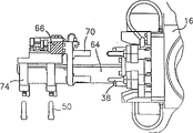
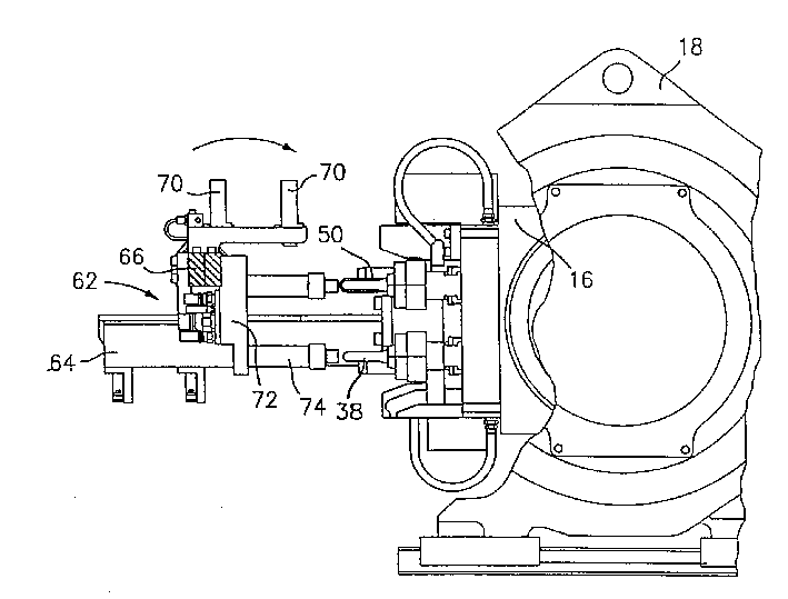
按照本发明的第一个实施例,当成形件处于冷却位置时,设备62对成形件进行冷却并且把它们从芯销38中移走。设备62包括机架64,机架64联接到传送架18或其支承装置上。交叉梁66连接到机架64上,从而使交叉梁66可以转动90度。同时通过所述90度的转动,使远离机架64的交叉梁66端部被连接到驱动设备68上。驱动设备68可以由已有的任何合适的驱动装置组成。According to the first embodiment of the invention, the
一套吹气管70被安装到端部或者联接到交叉梁66的传送盘72上的第一个面上。当成形件50在芯销38上时,吹气管70就用于引导制冷流体,如最典型的空气到成形件50的端部。吹气的位置图2b中已给出。冷却流体可以应用技术上已知的合适的任何方式供给到吹气管70中。A set of
一套冷却管74被固定在端部72的第二个表面上。从图1a中可以看出,冷却管74与吹气管70位置偏移了90度。冷却管74可使得把成形件50从芯销38上移走更容易。冷却管74借助于其内部的真空装置以已知的方式来协助移走已成形件50。例如,每根管道74的底部的气口(未标出)可以连接到真空源(未标出)上。管道74可以用冷却水等进行冷却,通过对流或传导的方式使其中的成形件50冷却。比如,可如在美国专利4,729,732中那样,通过成形件外表面与管道的内表面密切接触而达到冷却的目的。A set of
图3-6是本发明的造型机的操作程序。图3是夹具关闭和成形件50正在第一模芯系列A上被成形的图。图4表示夹具关闭和成形件正在第二模芯系列B上成形,此时冷空气从管道70被导引到第一模芯系列A的成形件50的端部。图5表示交叉梁66转动90度使第一模芯系列A上的成形件50对准冷却管74,然后成形件被移进管74中。已成形件50从芯销38移入到管74中是通过设备卸除设备来实现的,比如每个工作面36上的卸除销/套或脱盘。图6表示交叉梁66按反向转动90度,当前一系列成形件从冷却管74中移出时,后一系列成形件又一次对准了吹气管道70。已冷却的的成形件50可以通过多种方式从冷却管74中移出,比如借助于切断真空,靠重力使其从管道74中卸除,或者把成形件50从管中吹出,或者用如美国专利5,447,426号中提到的机械卸除方法。3-6 are the operating procedures of the molding machine of the present invention. FIG. 3 is a view of the clamps closed and the formed
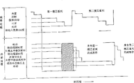
图7表示制备成形件50的操作程序。图的上半部分表示成形阶段,同时标明了两个完全相同的过程,第一个是第一模芯系列A;第二个是第二模芯系列B。每个过程都是从模具关闭开始,如图1a所示,然后是注射成形操作如夹紧、注射、保持/冷却和打开。在模具打开冲程期间,分度六角架16同时开始转动180度并对准第二模芯系列,此时,第一系列及其芯销38上的已成形件50对准了冷却和卸除设备62。转动架16在关闭冲程中转动完成。FIG. 7 shows the operation sequence for preparing the
图7的下半部分是冷却阶段,覆盖了图中上半部分的两个成形过程。卸除和冷却过程当带有成形件50的第一模芯系列A与冷却和卸除设备62对准时开始。冷却流体,如压缩空气直接从管道70直接吹到成形件50的端部使成形件50在芯销38上冷却。因此,在这一阶段,成形件50在内部和在外部都被冷却。然后端部72转动90度使芯销38上的已成形件50与冷却管74对准。下一步,与冷却管74内真空环路一起,成形机卸除系统把成形件从芯销38运送到冷却管74内,在此成形件因其外表面接触水冷管而立刻得到冷却。设备62马上再转动以便管道74朝向下方,使已成形件50在垂直方向上冷却,以保证对称冷却和重力的影响,使成形件保持无变形。已成形件50利用真空停留在管道74内继续冷却,直到恰是转动机构62向后转动去接来自第二模芯系列B的下一成形件的时候。因此,整个过程中已成形件的冷却时间包括在模具中和在芯销上以及在冷却管74内的时间。如图中阴影部分所示期间,通过管道70向成形件50吹空气进行了额外冷却。The lower part of Fig. 7 is the cooling stage, covering the two forming processes in the upper part of the figure. The unloading and cooling process begins when the first core series A with the formed
根据上文中对已成形件50最大化冷却时间的描述可以发现,最佳的成形周期仅需要两个模芯系列。因此,四工作面六角架可以减少到两工作面六角架以减少花费,同时模芯系列的花费也可以减半。From the above description of maximizing cooling time for the formed
从前面的描述可以看出,依据本发明,成形件冷却和卸除设备重量轻,并且它们被固定在移动的分度传送架上,因此可以通过吹空气使成形件50外部首先冷却,然后在冷却管74中成形件继续冷却,并从模具中移走。此外,成形件50在冷却管74内部在垂直方向上进行冷却。结果,成形件的性能得到了有益的改善。使用本发明的设备,在垂直方向上的时间可以得到优化。As can be seen from the foregoing description, according to the present invention, the cooling and unloading equipment of the formed parts are light in weight, and they are fixed on the moving index transfer frame, so the outside of the formed
现在参考图2c,可见能够使用备选的机构来转动仅包括冷却管74的端部72。从图中可以看出,端部72可以利用销钉连接76联接在机架64上,机架64固定在一个传送架18上。此外,柱塞缸型的致动件78也可以连接到机架64上。致动件的臂80可以连接到端部72的后部82。如图2c所示,冷却管74正对准了芯销38并且正在从那里移走成形件。为了转动端部72并把冷却管74移到垂直方向,启动件78缩回臂80以保证充分的垂直位置,如图中点画线所示。Referring now to Figure 2c, it can be seen that an alternative mechanism can be used to rotate the
现在参考图8a和8b,它们是本发明冷却装置的第二个实施例。在该实施例中,吹气管70已经被省去。但冷却设备62’有额外的冷却管74以达到多位置冷却的目的,这类似于美国再版专利33,237号所示的那样。Reference is now made to Figures 8a and 8b, which illustrate a second embodiment of the cooling device of the present invention. In this embodiment, the
如图8a所示,设备62’在分度造型机转动架的传送架18上固定在位置III上。设备62’有一个单侧机架84固定在传送架18之一上,它包括一个凸轮轨道86。凸轮88沿轨道86通过,它固定在可动的传送盘90上,传送盘90还固定着多位置冷却管74。在优选实施例中,传送盘90上的冷却管74的数量是六角转动架16的每个工作面上芯销38数量的两倍。如此数量的冷却管74使得已成形件能够在递次的成形周期中在冷却管74中冷却,从而达到了延长冷却时间的目的。As shown in Figure 8a, the device 62' is fixed in position III on the
致动器92固定在单侧机架84上,有轴颈连接器94联接在传送盘90上,这样当伸展活动杆96时,跟随凸轮轨道86传送盘90首先移动到垂直位置,然后如图8a所示,从垂直位置移动到水平位置,如图8b所示。这期间,带有成形件的第一系列冷却管74从与芯销38所对准的位置移开,而新的系列冷却管74准备好接受下一系列的成形件。当传送盘90在图8b所在的位置时,成形件50可以在垂直方向上冷却,准备好之后就排放在下面的传送带98上。致动器92可以由已知技术的任何合适的致动机构组成,比如象活塞缸构件。
图9a-9c是移动图8a中冷却设备62’所用的可选的致动系统,以使传送盘90可以从垂直位置移动到水平位置。在该实施例中,致动器92被固定在连接梁100的中央,连接梁100连接在机器10两侧的支承机架102。在这里,致动器92仅影响传送盘90的垂直位置。为了使传送盘90从垂直位置转动到如图9c所示的水平位置,提供了一个单独的致动器102,优选用活塞缸。致动器102带着传送盘在垂直方向移动,当它到达其垂直最末端时,致动器臂103移动并绕枢轴点105转动传送盘90以便冷却管74中的成形件50可以垂直定向。Figures 9a-9c illustrate an alternative actuation system for moving the cooling device 62' of Figure 8a so that the
图10a和10b也是冷却设备62’的致动系统的另一个实施例。在这里,两个汽缸104和106用于移动和转动传送盘。如图所示,包含冷却管74的传送盘72在枢轴108处连接到机架64上,机架64被连接在机器10的支承结构上。致动器或缸104可以通过已知技术的任何方式联接到传送盘72上,它用于使带有冷却管74的传送盘72在垂直方向上移动。这种移动也可以用已知技术的任何方式进行。致动器或汽缸106被连接到传送盘72,它用于绕枢轴点108来转动传送盘72以便管道74确保垂直方向。Figures 10a and 10b are also another embodiment of the actuation system of the cooling device 62'. Here, two
从前面的讨论可以知道,在图8-10的实施例中,提供了一种联接到分度传送机构的轻量、多位置的冷却传送盘,使得成形件可以从模具中水平移走并且在垂直方向冷却和卸除,而且使用多冷却管延长了冷却时间。As can be seen from the foregoing discussion, in the embodiment of Figures 8-10, a lightweight, multi-position cooling carousel coupled to an indexing car Vertical cooling and removal, and the use of multiple cooling tubes prolongs the cooling time.
Claims (14)
Applications Claiming Priority (2)
| Application Number | Priority Date | Filing Date | Title |
|---|---|---|---|
| US09/167,699 US6059557A (en) | 1998-10-07 | 1998-10-07 | Cooling device attached to index machine |
| US09/167,699 | 1998-10-07 |
Related Parent Applications (1)
| Application Number | Title | Priority Date | Filing Date |
|---|---|---|---|
| CN99121620A Division CN1103671C (en) | 1998-10-07 | 1999-10-08 | Cooling equipment, molding machine equipped with the cooling equipment and its process |
Publications (2)
| Publication Number | Publication Date |
|---|---|
| CN1389336A CN1389336A (en) | 2003-01-08 |
| CN1166503C true CN1166503C (en) | 2004-09-15 |
Family
ID=22608448
Family Applications (2)
| Application Number | Title | Priority Date | Filing Date |
|---|---|---|---|
| CNB021060398A Expired - Fee Related CN1166503C (en) | 1998-10-07 | 1999-10-08 | Apparatus and methods for forming cooled shaped parts |
| CN99121620A Expired - Fee Related CN1103671C (en) | 1998-10-07 | 1999-10-08 | Cooling equipment, molding machine equipped with the cooling equipment and its process |
Family Applications After (1)
| Application Number | Title | Priority Date | Filing Date |
|---|---|---|---|
| CN99121620A Expired - Fee Related CN1103671C (en) | 1998-10-07 | 1999-10-08 | Cooling equipment, molding machine equipped with the cooling equipment and its process |
Country Status (5)
| Country | Link |
|---|---|
| US (2) | US6059557A (en) |
| JP (1) | JP3253939B2 (en) |
| KR (1) | KR100342196B1 (en) |
| CN (2) | CN1166503C (en) |
| CA (1) | CA2285512C (en) |
Families Citing this family (19)
| Publication number | Priority date | Publication date | Assignee | Title |
|---|---|---|---|---|
| US6168416B1 (en) | 1998-12-22 | 2001-01-02 | Husky Injection Molding Systems Ltd. | Cooling device for molded articles |
| US6461141B1 (en) | 2000-11-30 | 2002-10-08 | Wentworth Mold, Inc., Electra Form Industries Division | Cam track with adjustable pre-release |
| US6802705B2 (en) * | 2001-09-10 | 2004-10-12 | Husky Injection Molding Systems Ltd. | Post mold cooling assembly for molded article neck finishes |
| JP4549846B2 (en) * | 2002-05-17 | 2010-09-22 | ハスキー インジェクション モールディング システムズ リミテッド | Post-molding cooling apparatus and method with rotational and lateral motion |
| US6817855B2 (en) * | 2002-05-17 | 2004-11-16 | Husky Injection Molding Systems Ltd. | Apparatus for post mold cooling of plastic pieces |
| US6848900B2 (en) * | 2002-07-13 | 2005-02-01 | Husky Injection Molding Systems Ltd. | Apparatus for handling injection molded preforms |
| US7104779B2 (en) * | 2002-12-20 | 2006-09-12 | Husky Injection Molding Systems, Ltd. | Suction sleeve extension for a take-off device |
| ITRM20030461A1 (en) * | 2003-10-07 | 2005-04-08 | Sipa Societa Industrializzazione P Rogettazione A | PLASTIC DEVICE AND PROCESS OF CONDITIONING OBJECTS. |
| ITRM20040107A1 (en) * | 2004-03-02 | 2004-06-02 | Sipa Societa Industrializzazio | DEVICE AND CONDITIONING METHOD OF PLASTIC OBJECTS. |
| US7632089B2 (en) * | 2004-05-07 | 2009-12-15 | Graham Packaging Pet Technologies, Inc. | Take out and cooling system and method |
| US7946836B2 (en) * | 2008-05-23 | 2011-05-24 | Roberto Sicilia | Injection molding and temperature conditioning apparatus |
| EP2786855B1 (en) * | 2013-04-04 | 2015-01-21 | Magna Steyr Fuel Systems GesmbH | Device and method for manufacturing plastic containers |
| CN104385490B (en) * | 2014-11-30 | 2019-04-09 | 重庆锦冈机械有限公司 | Processing cup shell swings to extrusion die |
| CN105108945A (en) * | 2015-09-22 | 2015-12-02 | 重庆市合川区环宇配件厂 | Automobile accessory cooling setting machine |
| CN105108946A (en) * | 2015-09-22 | 2015-12-02 | 重庆市合川区环宇配件厂 | Assembly for cooling and forming after high temperature mould pressing |
| ES2663259T3 (en) * | 2016-04-15 | 2018-04-11 | Güven Teknik Makina Ve Kalip San. Dis Tic. Ltd. Sti. | Machine and method for producing thermoformed items, which presents an improved stacking system |
| CN107984715B (en) * | 2017-12-13 | 2021-04-20 | 惠州市益新致能模具有限公司 | Plastic mold processing is with injection molding machine mold taking mechanism |
| CN110480966A (en) * | 2018-05-15 | 2019-11-22 | 泰科电子(上海)有限公司 | Injection mould cooling system |
| CN116533439A (en) * | 2023-07-07 | 2023-08-04 | 常州市中佳塑业有限公司 | Injection molding machine with rotary conveying feeding and discharging mechanism |
Family Cites Families (6)
| Publication number | Priority date | Publication date | Assignee | Title |
|---|---|---|---|---|
| US33237A (en) * | 1861-09-10 | Window-sash fastener | ||
| US4729732A (en) * | 1985-05-14 | 1988-03-08 | Husky Injection Molding Systems Ltd. | Carrying means for holding and cooling a parison |
| USRE33237E (en) | 1987-03-23 | 1990-06-19 | Husky Injection Molding Systems Ltd. | Apparatus for producing hollow plastic articles |
| US5447426A (en) * | 1993-07-06 | 1995-09-05 | Husky Injection Molding Systems Ltd. | Take-off plate device |
| US5728409A (en) * | 1996-03-06 | 1998-03-17 | Husky Injection Molding Systems Ltd. | Turret article molding machine |
| US5837301A (en) * | 1997-04-28 | 1998-11-17 | Husky Injection Molding Systems Ltd. | Injection molding machine having a high speed turret |
-
1998
- 1998-10-07 US US09/167,699 patent/US6059557A/en not_active Expired - Fee Related
- 1998-12-18 US US09/215,819 patent/US6123538A/en not_active Expired - Fee Related
-
1999
- 1999-09-21 KR KR1019990040566A patent/KR100342196B1/en not_active Expired - Fee Related
- 1999-10-07 CA CA002285512A patent/CA2285512C/en not_active Expired - Fee Related
- 1999-10-07 JP JP28742299A patent/JP3253939B2/en not_active Expired - Fee Related
- 1999-10-08 CN CNB021060398A patent/CN1166503C/en not_active Expired - Fee Related
- 1999-10-08 CN CN99121620A patent/CN1103671C/en not_active Expired - Fee Related
Also Published As
| Publication number | Publication date |
|---|---|
| CN1249988A (en) | 2000-04-12 |
| JP2000108186A (en) | 2000-04-18 |
| KR100342196B1 (en) | 2002-06-27 |
| CA2285512C (en) | 2004-06-22 |
| CN1389336A (en) | 2003-01-08 |
| US6123538A (en) | 2000-09-26 |
| KR20000028701A (en) | 2000-05-25 |
| CN1103671C (en) | 2003-03-26 |
| CA2285512A1 (en) | 2000-04-07 |
| US6059557A (en) | 2000-05-09 |
| JP3253939B2 (en) | 2002-02-04 |
Similar Documents
| Publication | Publication Date | Title |
|---|---|---|
| CN1166503C (en) | Apparatus and methods for forming cooled shaped parts | |
| KR100642715B1 (en) | Post-molding cooling apparatus and its method for rotating and transverse movement | |
| US7056465B2 (en) | Post mold cooling apparatus and method having transverse movement | |
| CN1159144C (en) | Small cooling device after ejection | |
| CA2154826C (en) | Parison molding apparatus and method | |
| US7871259B2 (en) | Method and device for blow-molding containers | |
| US6848900B2 (en) | Apparatus for handling injection molded preforms | |
| JP4372548B2 (en) | Cooling after pre-molding | |
| CN1009632B (en) | Apparatus for locking top mould of blow-moulding machine | |
| CN1356937A (en) | Feeding of injection molded preforms in the mold of an efficient blow molding machine | |
| CN1156366C (en) | Method and apparatus for producing containers by blowing blanks of thermoplastic material | |
| CN1086478A (en) | The method and apparatus of injection stretch blow molding | |
| CN86108754A (en) | Molds for molding blanks | |
| JP3649631B2 (en) | Cooling system | |
| CN101076437A (en) | Device for cooling after moulded and component repairing | |
| US5919498A (en) | Apparatus for applying labels to blow-molded articles | |
| CN1599700A (en) | Apparatus for molding glass articles for cathode ray tubes | |
| US7258542B2 (en) | Mold assembly for blow molding plastic articles and method of use | |
| EP0992330A2 (en) | Cooling device attached to molding machine with rotary turret block | |
| US3659998A (en) | Blow-molding machines | |
| CN220447137U (en) | Automatic bottle blowing machine | |
| CN1251855C (en) | Continuous molding bottle forming machine | |
| CN222523609U (en) | Transfer device for metal ceramic tube pressing die | |
| CN113665075B (en) | Pre-pressing and rapid cooling process method for molded product | |
| CN119840138A (en) | Multifunctional efficient energy-saving hollow extrusion blow molding machine |
Legal Events
| Date | Code | Title | Description |
|---|---|---|---|
| C10 | Entry into substantive examination | ||
| SE01 | Entry into force of request for substantive examination | ||
| C06 | Publication | ||
| PB01 | Publication | ||
| C10 | Entry into substantive examination | ||
| SE01 | Entry into force of request for substantive examination | ||
| C14 | Grant of patent or utility model | ||
| GR01 | Patent grant | ||
| C19 | Lapse of patent right due to non-payment of the annual fee | ||
| CF01 | Termination of patent right due to non-payment of annual fee |