EP0992330A2 - Cooling device attached to molding machine with rotary turret block - Google Patents
Cooling device attached to molding machine with rotary turret block Download PDFInfo
- Publication number
- EP0992330A2 EP0992330A2 EP99119167A EP99119167A EP0992330A2 EP 0992330 A2 EP0992330 A2 EP 0992330A2 EP 99119167 A EP99119167 A EP 99119167A EP 99119167 A EP99119167 A EP 99119167A EP 0992330 A2 EP0992330 A2 EP 0992330A2
- Authority
- EP
- European Patent Office
- Prior art keywords
- cooling
- molded part
- carrier plate
- mold
- movable mold
- Prior art date
- Legal status (The legal status is an assumption and is not a legal conclusion. Google has not performed a legal analysis and makes no representation as to the accuracy of the status listed.)
- Withdrawn
Links
Images


Classifications
-
- B—PERFORMING OPERATIONS; TRANSPORTING
- B29—WORKING OF PLASTICS; WORKING OF SUBSTANCES IN A PLASTIC STATE IN GENERAL
- B29C—SHAPING OR JOINING OF PLASTICS; SHAPING OF MATERIAL IN A PLASTIC STATE, NOT OTHERWISE PROVIDED FOR; AFTER-TREATMENT OF THE SHAPED PRODUCTS, e.g. REPAIRING
- B29C45/00—Injection moulding, i.e. forcing the required volume of moulding material through a nozzle into a closed mould; Apparatus therefor
- B29C45/17—Component parts, details or accessories; Auxiliary operations
- B29C45/72—Heating or cooling
- B29C45/7207—Heating or cooling of the moulded articles
-
- B—PERFORMING OPERATIONS; TRANSPORTING
- B29—WORKING OF PLASTICS; WORKING OF SUBSTANCES IN A PLASTIC STATE IN GENERAL
- B29C—SHAPING OR JOINING OF PLASTICS; SHAPING OF MATERIAL IN A PLASTIC STATE, NOT OTHERWISE PROVIDED FOR; AFTER-TREATMENT OF THE SHAPED PRODUCTS, e.g. REPAIRING
- B29C35/00—Heating, cooling or curing, e.g. crosslinking or vulcanising; Apparatus therefor
- B29C35/16—Cooling
-
- B—PERFORMING OPERATIONS; TRANSPORTING
- B29—WORKING OF PLASTICS; WORKING OF SUBSTANCES IN A PLASTIC STATE IN GENERAL
- B29C—SHAPING OR JOINING OF PLASTICS; SHAPING OF MATERIAL IN A PLASTIC STATE, NOT OTHERWISE PROVIDED FOR; AFTER-TREATMENT OF THE SHAPED PRODUCTS, e.g. REPAIRING
- B29C45/00—Injection moulding, i.e. forcing the required volume of moulding material through a nozzle into a closed mould; Apparatus therefor
- B29C45/03—Injection moulding apparatus
- B29C45/04—Injection moulding apparatus using movable moulds or mould halves
- B29C45/0441—Injection moulding apparatus using movable moulds or mould halves involving a rotational movement
- B29C45/045—Injection moulding apparatus using movable moulds or mould halves involving a rotational movement mounted on the circumference of a rotating support having a rotating axis perpendicular to the mould opening, closing or clamping direction
-
- B—PERFORMING OPERATIONS; TRANSPORTING
- B29—WORKING OF PLASTICS; WORKING OF SUBSTANCES IN A PLASTIC STATE IN GENERAL
- B29K—INDEXING SCHEME ASSOCIATED WITH SUBCLASSES B29B, B29C OR B29D, RELATING TO MOULDING MATERIALS OR TO MATERIALS FOR MOULDS, REINFORCEMENTS, FILLERS OR PREFORMED PARTS, e.g. INSERTS
- B29K2105/00—Condition, form or state of moulded material or of the material to be shaped
- B29K2105/25—Solid
- B29K2105/253—Preform
Definitions
- the present invention relates to an improved molding machine, in particular, a two faced index molding machine, having improved part cooling and part removal.
- U.S. Patent No. 4,729,732 and U.S. Reissue Patent No. 33,237, both assigned to the assignee of the instant application, show a multi-position tooling plate with water cooled tubes used to remove and cool preforms from a conventional preform molding machine.
- the tooling plate design shown in these patents has two disadvantages. First, the robot mechanism occupies a substantial floor area adjacent the machine. Second, the preforms are cooled inside their tubes in a horizontal orientation. This has been found to be detrimental in that the weight of the preform causes it to press more firmly against the lower portion of the cooling tube while its upper surface tends to separate from the upper portion of the cooling tube. This unequal contact force with the cooling surface tends to promote unequal cooling of the preform from one side to the other.
- a vertical orientation during cooling provides a symmetrical weight distribution with a balanced heat removal result.
- Conventional index molding machines eject parts at the lowermost station, i.e., when the molded parts to be ejected are under the turret block. There is a need to accommodate part ejection/removal at a station opposite to the molding station to permit two faced turret operation in a molding cycle where the turret rotates 180 degrees each time the mold opens instead of rotating 90 degrees at each mold opening.
- a cooling device for use with an index molding machine having a rotary turret block mounted within support means and at least one mold core on each of at least two faces of said rotary turret block.
- the cooling device broadly comprises frame means attached to said rotary turret block support means, means for receiving and cooling at least one molded part, said receiving and cooling means being mounted to a first surface of a carrier plate connected to said frame means, and means for moving said carrier plate between a first orientation where said receiving and cooling means is aligned with said at least one molded part and a second orientation where said at least one molded part is preferably vertically oriented while being cooled within said receiving and cooling means.
- the process of the present invention broadly comprises the steps of providing an index molding machine having a first platen carrying a first mold half having at least one mold cavity and a second platen comprising rotatable turret block means rotatable on a central axis of rotation for rotating at least two movable mold halves into alignment with the first mold half, each of the movable mold halves having at least one mold core, moving the rotatable turret block means to bring a first one of said movable mold halves into a mold closed position with said first mold half and clamping the first one of the movable mold halves and the first mold half, injecting molten material into the at least one mold cavity to form a first molded part set comprising at least one molded part, holding the first one of the movable mold halves in the mold closed and clamped position while cooling the first molded part set, moving the rotatable turret block means to a mold open position where the first set is positioned on the at least one mold core on the first one
- the process further comprises forming a second set of molded part(s) on mold core(s) on a second one of the movable mold halves while the molded part(s) in the first set is being cooled and thereafter rotating the rotatable turret block so that said second set of molded part(s) is in said cooling position and subjecting the second set of molded part(s) to cooling.
- FIGS. 1a and 1b illustrate a two tiebar index molding machine 10 of the type shown in copending U.S. patent application no. 09/070,598, to Galt et al., entitled Tiebar Structure for Injection Molding Machine, filed April 30, 1998, which is incorporated by reference herein.
- the index molding machine 10 includes a base 12, a fixed platen 14, and a movable platen 16 which is movable with respect to the fixed platen 14.
- the movable platen 16 is a two-faced rotary turret block, which is positioned within the movable platen, with pinions in bearings mounted in carriers 18 that slide on the base 12.
- the turret block 16 is rotated or indexed on a central axis 20 so that the faces thereof represent two positions in an injection molding cycle.
- the rotatable turret block 16 is rotatable on a central axis of rotation 20 for rotating a plurality of movable mold halves 36 attached thereto into alignment with a first mold half 32 carried by the fixed platen 14.
- Each movable mold half 36 includes at least one mold core 38 and is matable with the first mold half 32 for forming a mold for forming at least one molded article, with the mold halves being clamped together as will be described hereinafter.
- the first mold half 32 may be joined to the fixed platen 14 in any suitable manner known in the art and may contain one or more mold cavities 34 which together with the mold core(s) 38 form one or more mold cavity spaces 40.
- Parts 50 such as preforms, are molded by injecting plastic material through the mold half 32 from an injection unit (not shown) into the cavity space(s) 40 formed by the closed mold.
- Two tiebars 24 are provided and bolted to the carriers 18, each of which includes an inside stroke cylinder 22, the rod 23 of which is fixed to housing 25 which in turn is bolted to fixed platen 14.
- Each tiebar 24 includes external teeth 26 of a rotating clamp piston 30 with the clamp piston contained in fixed platen 14.
- the clamp piston 30 includes a row of teeth 28 and an adjacent row free from teeth so that on rotation of the clamp piston, the clamp piston teeth 28 alternately engage and disengage the tiebar teeth 26.
- Clamp piston 30 may be rotated by any desired and convenient means (not shown), such as a cylinder means acting on a pin via a slot in housing 25, such as a cylinder bolted to the fixed platen 14 with linkage means connecting the pins together and causing rotation of the pistons 30.
- a pin rotates clamp piston 30 so that clamp piston teeth 28 are disengaged from teeth 26 on tiebars 24.
- High pressure oil is then supplied to the piston end 42 of stroke cylinder 22 via a line (not shown) causing stroke cylinder rod 23 to extend and move carriers 18 and turret block 16 away from the fixed platen 14, thereby opening the mold.
- oil is supplied to the rod side 44 of stroke cylinder 22 via a line (not shown), thereby retracting stroke cylinder rod 23 and closing the clamp until the mold is closed.
- the aforementioned pin (not shown) is then activated by a cylinder (not shown) and linkage means (not shown) to engage clamp piston teeth 28 with tiebar teeth 26.
- High pressure oil is then provided to the clamp piston cylinder 46 causing the clamp pistons to clamp the mold.
- high pressure oil is provided to the mold break cylinder 48 causing clamp piston 30 to act on the back side of tiebar teeth 26 and urge the mold open.
- clamp piston 30 is de-energized and the pin actuated by the aforementioned cylinder and linkage means causes the clamp piston to rotate to disengage clamp piston teeth 28 from tiebar teeth 26 so that stroke cylinder 22 can open the mold.
- the turret block 16 has two faces, each with a mold core plate 36 mounted to it.
- Each mold core plate 36 may be mounted to a respective face of the turret block 16 using any suitable conventional means known in the art.
- each mold core plate 36 has a plurality of core pins 38, equal in number to the number of mold cavities 34 in the first mold half 32.
- a first set A of core pins 38 is aligned with the mold cavities 34 in a molding position, while a second set B of core pins 38 are in a cooling position located 180 degrees from the molding position.
- the parts 50 are partially cooled in a customary manner by cooling circuits (not shown), such as water cooling circuits, in the mold cavity plate 32 and in the core pins 38.
- cooling circuits such as water cooling circuits
- the mold is opened in the manner previously discussed and the molded parts 50 on the first set A of core pins 38 are withdrawn from the mold cavities 34.
- the turret block 16 is then rotated 180 degrees to present the second set B of core pins 38 for molding while the first set A of core pins 38, complete with the molded parts 50 thereon, are presented at the opposite side of the turret block for further cooling.
- a device 62 is provided to cool the molded parts and remove them from the core pins 38 when the molded parts are in the cooling position.
- the device 62 includes a frame 64 attached to the carrier 18 or its support.
- a cross beam 66 is attached to the frame 64 so as to be capable of rotation through a 90 degree angle.
- the end of the cross beam 66 remote from the frame 64 is connected to a drive means 68 for rotating the cross beam 66 through said 90 degree rotation.
- the drive means 68 may comprise any suitable drive means known in the art.
- a set of blowing tubes 70 is mounted to a first surface of a head or carrier plate 72 attached to the cross beam 66.
- the blowing tubes 70 are used to direct a cooling fluid, typically air, toward an end of the molded parts 50, while the parts 50 are on the core pins 38. This blowing position is shown in FIG. 2b. Cooling fluid may be supplied to the blowing tubes 70 in suitable manner known in the art.
- a set of cooling tubes 74 is mounted to a second surface of the head 72. As can be seen from FIG. 2a, the cooling tubes 74 are offset 90 degrees from the blowing tubes 70. The set of cooling tubes 74 are used to facilitate removal of the molded parts 50 from the core pins 38. The cooling tubes 74 assist the removal of the molded parts 50 through the application of a vacuum inside the tubes 74 in a known fashion. For example, a port (not shown) in the bottom of each tube 74 may be connected to a vacuum source (not shown).
- the tubes 74 may be cooled by a fluid, such as chilled water, and remove heat from the parts 50 positioned therein either by convection or conduction. For example, cooling may be achieved by intimate contact between exterior surface of the part and the inside surface of the tube as taught by U.S. Patent No. 4,729,732, which is incorporated by reference herein.
- FIG. 3 - 6 illustrate the sequence of operation of a molding machine in accordance with the present invention.
- FIG. 3 shows the clamp closed and the parts 50 being molded on the first core set A.
- FIG. 4 shows the clamp closed for molding on the second core set B while cooling air is being directed from tubes 70 onto the ends of the molded parts 50 on the first core set A.
- FIG. 5 shows the cross beam 66 rotated 90 degrees to align the cooling tubes 74 with the parts 50 on the first core set A as the parts are ejected into the tubes 74.
- Ejection of the molded parts 50 from the core pins 38 into tubes 74 is carried out by the provision of ejection means, such as ejection pins/sleeves or an ejection plate, on each mold face 36.
- FIG. 3 shows the clamp closed and the parts 50 being molded on the first core set A.
- FIG. 4 shows the clamp closed for molding on the second core set B while cooling air is being directed from tubes 70 onto the ends of the molded parts 50 on the first
- FIG. 6 shows cross beam 66 rotated 90 degrees in the reverse direction to once again align the blowing tubes 70 with the next set of molded parts while the previous set of parts are ejected from cooling tubes 74.
- Ejection of the cooled parts 50 from the cooling tubes 74 may be effected by discontinuing the vacuum and allowing gravity to cause the parts to drop out of the tubes 74 or by blowing the parts 50 out of the tubes 74 or by mechanical ejection means such as those shown in U.S. Patent No. 5,447,426, which is incorporated by reference herein.
- FIG. 7 shows the sequence of operation for making the molded parts 50.
- the top half of the chart shows the molding process and indicates two identical sequences spaced in time, the first for the first core set A, and the second for the second core set B.
- Each of the sequences starts with the mold closed, as shown in FIG. 1a.
- the injection molding sequence of clamp, inject, hold/cool, and open then follows.
- the index turret block 16 simultaneously begins to rotate 180 degrees to align the second core set for molding while the first core set, with the molded parts 50 on the core pins 38, is aligned to the cooling and removal device 62.
- the rotation is completed during the closing stroke of the turret block 16.
- the bottom half of the chart shows the cooling process and indicates a sequence that overlaps the two molding processes shown in the top half of the chart.
- the ejection and cooling sequence begins as the first core set A with molded parts 50 thereon is aligned to the cooling and removal device 62. Cooling fluid, typically compressed air, is blown from tubes 70 directly onto the ends of the molded parts 50, as they remain cooling on the core pins 38. Thus, during this portion of the sequence, parts 50 are cooled both internally and externally. Then the head 72 is rotated 90 degrees to align the cooling tubes 74 with the molded parts 50 on the core pins 38.
- Cooling fluid typically compressed air
- the ejection system of the mold in combination with the vacuum circuit in the cooling tubes 74 transfers the parts from the core pins 38 to the tubes 74 wherein the parts are immediately cooled on their outer surfaces by their contact with the water cooled tubes, in a known fashion.
- the device 62 is immediately rotated again so that the tubes 74 point downward and the molded parts 50 continue cooling in a vertical orientation to ensure symmetrical cooling and gravitational effects maintaining a distortion-free part.
- the molded parts 50 are held in the tubes 74 by the applied vacuum and continue to cool until just before it is time to rotate the device 62 back to receive the next set of molded parts from the second core set B.
- the cooling time for the complete process optimizes the time the molded parts 50 are cooled, first while in the mold and on the cores and secondly while in the cooling tubes 74. Additional cooling is provided by the air blowing from tubes 70 onto the parts 50 during the shaded portion shown on the chart.
- a lightweight cooling and part removal device mounted on the moving index carrier that first cools the outside of the part 50 by blowing air and subsequently continues to cool the part 50 inside a cooled tube 74 that also removes the part 50 from the mold. Still further, cooling of the part 50 is performed in a vertical orientation inside a cooled tube 74. As a result, the part 50 has improved properties which are beneficial. Using the device of the present invention, time in this vertical orientation is optimized.
- an alternative mechanism can be used to rotate a head 72 containing only cooling tubes 72.
- the head 72 may be attached to a frame 64 mounted to one of the carriers 18 by pin connection 76.
- a piston-cylinder type of actuation unit 78 may be connected to the frame 64.
- the arm 80 of the actuation unit may be connected to a rear portion 82 of the head 72.
- the cooling tubes 74 are aligned with core pins 38 and are removing molded articles therefrom.
- the actuation unit 78 retracts arm 80 and assumes the substantially vertical position shown in dotted lines in the figure.
- FIGS. 8a and 8b a second embodiment of the cooling device of the present invention is illustrated.
- blowing tubes 70 have been omitted.
- the cooling device 62' has additional cooling tubes 74 so that multi-position cooling can be effected in a manner similar to that illustrated in U.S. Reissue Patent No. 33,237, which is incorporated by reference herein.
- the device 62' is mounted in position III on the index machine turret carriage 18.
- the device 62' has a single side frame 84 mounted to one of the carriers 18 which contains a cam track profile 86.
- the profile 86 is followed by a cam follower 88 mounted to a movable carrier plate 90 on which are mounted multiple cooling tubes 74.
- the number of cooling tubes 74 on the carrier plate 90 is twice the number of core pins 38 on each face of the turret block 16.
- the actuator 92 may comprise any suitable actuator known in the art such as piston-cylinder unit.
- FIGS. 9a - 9c illustrate an alternative actuation system for moving the cooling device 62' of FIG. 8a so that the carrier plate 90 moves from a vertical orientation to a horizontal orientation.
- the actuator 92 is centrally mounted on a bridge 100 connecting support frames 101 on both sides of the machine 10.
- the actuator 92 in this arrangement, only effects the vertical positioning of the carrier plate 90.
- a separate actuator 102 preferably in the form of a piston-cylinder unit, is provided.
- the actuator 102 moves vertically with the carrier plate and when it reaches the end of its vertical travel, the actuator arm 103 is moved to rotate the carrier plate 90 about the pivot point 105 so that the parts 50 in the cooling tubes 74 is vertically oriented.
- FIGS. 10a and 10b illustrate yet another embodiment of an actuation system for the cooling device 62'.
- two cylinders 104 and 106 are used to translate and rotate the carrier plate.
- the carrier plate 72 containing the cooling tubes 74 is pivotally connected at pivot 108 to the frame 64 which is connected to a support structure on the machine 10.
- the actuator or cylinder 104 may be attached to carrier plate 72 in any suitable manner known in the art and is used to translate the carrier plate 72 with tubes 74 in a vertical direction. This translation may be carried out in any suitable manner known in the art.
- the actuator or cylinder 106 is connected to the carrier plate 72 and is used to rotate the carrier plate 72 about pivot point 108 so that tubes 74 assume a vertical orientation.
- FIGS. 8 - 10 there has been provided in the embodiments of FIGS. 8 - 10, a lightweight, multi-position cooling carrier plate arrangement for attachment to an index carrier that removes parts horizontally from the mold and cools and ejects them in a vertical orientation, while extending cooling time with multiple tubes.
Abstract
Description
- The present invention relates to an improved molding machine, in particular, a two faced index molding machine, having improved part cooling and part removal.
- Index molding machines are known in the art. U.S. Patent No. 5,728,409, assigned to the assignee of the instant application, shows a four faced turret block with a temperature conditioning station mounted to the turret for directing cooling air onto newly molded articles and a tubular part removal system using an air conveyor. Currently, there is a need for a lower cost molding machine which employs only a two faced turret block and correspondingly half the number of core sets of tooling.
- Co-pending, allowed U.S. Patent Application Serial No. 08/847,895 to Arnott et al., entitled Injection Molding Machine Having a High Speed Turret, filed April 28, 1997, also assigned to the assignee of the instant application, shows an index molding machine with a two faced turret block. This application however does not discuss the problems of part cooling and controlled part removal.
- Co-pending U.S. Patent Application Serial No. 09/070,598, to Galt et al., filed April 30, 1998, entitled Tiebar Structure for Injection Molding Machine, also assigned to the assignee of the instant application, shows a two tiebar index molding machine. Here again, there is no discussion of part cooling or part removal.
- U.S. Patent No. 4,729,732 and U.S. Reissue Patent No. 33,237, both assigned to the assignee of the instant application, show a multi-position tooling plate with water cooled tubes used to remove and cool preforms from a conventional preform molding machine. The tooling plate design shown in these patents has two disadvantages. First, the robot mechanism occupies a substantial floor area adjacent the machine. Second, the preforms are cooled inside their tubes in a horizontal orientation. This has been found to be detrimental in that the weight of the preform causes it to press more firmly against the lower portion of the cooling tube while its upper surface tends to separate from the upper portion of the cooling tube. This unequal contact force with the cooling surface tends to promote unequal cooling of the preform from one side to the other. A vertical orientation during cooling provides a symmetrical weight distribution with a balanced heat removal result.
- Conventional index molding machines eject parts at the lowermost station, i.e., when the molded parts to be ejected are under the turret block. There is a need to accommodate part ejection/removal at a station opposite to the molding station to permit two faced turret operation in a molding cycle where the turret rotates 180 degrees each time the mold opens instead of rotating 90 degrees at each mold opening.
- Accordingly, it is an object of the present invention to provide a two faced turret molding machine having improved part cooling and improved part removal.
- It is a further object of the present invention to provide a molding machine as above which is less expensive to produce.
- It is yet a further object of the present invention to provide a molding machine as above which allows cooling of the molded part in a vertical orientation.
- The foregoing objects are achieved by the molding machine, the cooling device, and the process of the present invention.
- In accordance with the present invention, there is provided a cooling device for use with an index molding machine having a rotary turret block mounted within support means and at least one mold core on each of at least two faces of said rotary turret block. The cooling device broadly comprises frame means attached to said rotary turret block support means, means for receiving and cooling at least one molded part, said receiving and cooling means being mounted to a first surface of a carrier plate connected to said frame means, and means for moving said carrier plate between a first orientation where said receiving and cooling means is aligned with said at least one molded part and a second orientation where said at least one molded part is preferably vertically oriented while being cooled within said receiving and cooling means.
- The process of the present invention broadly comprises the steps of providing an index molding machine having a first platen carrying a first mold half having at least one mold cavity and a second platen comprising rotatable turret block means rotatable on a central axis of rotation for rotating at least two movable mold halves into alignment with the first mold half, each of the movable mold halves having at least one mold core, moving the rotatable turret block means to bring a first one of said movable mold halves into a mold closed position with said first mold half and clamping the first one of the movable mold halves and the first mold half, injecting molten material into the at least one mold cavity to form a first molded part set comprising at least one molded part, holding the first one of the movable mold halves in the mold closed and clamped position while cooling the first molded part set, moving the rotatable turret block means to a mold open position where the first set is positioned on the at least one mold core on the first one of the movable mold halves, rotating the turret block to bring the first molded part set to a cooling position, providing a cooling device on a carrier plate adjacent said cooling position, said cooling device having at least one cooling tube for receiving the first molded part set into the at least one cooling tube, rotating said at least one cooling tube to a position where each said molded part in said first set is in a desired orientation, preferably vertically, and cooling each said molded part in the first set while it is in said desired orientation. The process further comprises forming a second set of molded part(s) on mold core(s) on a second one of the movable mold halves while the molded part(s) in the first set is being cooled and thereafter rotating the rotatable turret block so that said second set of molded part(s) is in said cooling position and subjecting the second set of molded part(s) to cooling.
- Other details of the molding machine, cooling device, and the process of the present invention, as well as other objects and advantages attendant thereto, are set forth in the following detailed description and the accompanying drawings wherein like reference numerals depict like elements.
-
- FIG. 1a is a side view of a two tiebar index molding machine;
- FIG. 1b is an end view of the molding machine of FIG. 1a;
- FIG. 2a is a side view of a first embodiment of a cooling device in accordance with the present invention;
- FIG. 2b is a side view of the cooling device of FIG. 2a showing the cooling tubes in a part removing position;
- FIG. 2c illustrates an alternative actuation system for moving the cooling device of FIG. 2a between positions;
- FIG. 3 is a partial sectional view of the molding machine of FIG. 1a;
- FIG. 4 is a partial sectional view of the molding machine of FIG. 1a;
- FIG. 5 is a partial sectional view of the molding machine of FIG. 1a in a part transferring mode;
- FIG. 6 is a partial sectional view of the molding machine of FIG. 1a with the cooling device ejecting cooled molded parts;
- FIG. 7 is a chart showing the sequence of operation of the molding machine of FIG. 1a;
- FIGS. 8a and 8b illustrate an alternative embodiment of a cooling device having multi-position cooling tubes for use with an index molding machine;
- FIGS. 9a - 9c illustrate an alternative actuation system for the cooling device of FIGS. 8a and 8b; and
- FIGS. 10a and 10b illustrate another alternative actuation system for the cooling device of FIGS. 8a and 8b.
-
- Referring now to the drawings, FIGS. 1a and 1b illustrate a two tiebar
index molding machine 10 of the type shown in copending U.S. patent application no. 09/070,598, to Galt et al., entitled Tiebar Structure for Injection Molding Machine, filed April 30, 1998, which is incorporated by reference herein. Theindex molding machine 10 includes abase 12, afixed platen 14, and amovable platen 16 which is movable with respect to the fixedplaten 14. Themovable platen 16 is a two-faced rotary turret block, which is positioned within the movable platen, with pinions in bearings mounted incarriers 18 that slide on thebase 12. Theturret block 16 is rotated or indexed on acentral axis 20 so that the faces thereof represent two positions in an injection molding cycle. Thus, therotatable turret block 16 is rotatable on a central axis ofrotation 20 for rotating a plurality of movable mold halves 36 attached thereto into alignment with afirst mold half 32 carried by the fixedplaten 14. Eachmovable mold half 36 includes at least onemold core 38 and is matable with thefirst mold half 32 for forming a mold for forming at least one molded article, with the mold halves being clamped together as will be described hereinafter. - The
first mold half 32 may be joined to the fixedplaten 14 in any suitable manner known in the art and may contain one or more mold cavities 34 which together with the mold core(s) 38 form one or moremold cavity spaces 40.Parts 50, such as preforms, are molded by injecting plastic material through themold half 32 from an injection unit (not shown) into the cavity space(s) 40 formed by the closed mold. - Two
tiebars 24 are provided and bolted to thecarriers 18, each of which includes aninside stroke cylinder 22, therod 23 of which is fixed tohousing 25 which in turn is bolted to fixedplaten 14. Eachtiebar 24 includesexternal teeth 26 of arotating clamp piston 30 with the clamp piston contained in fixedplaten 14. Theclamp piston 30 includes a row ofteeth 28 and an adjacent row free from teeth so that on rotation of the clamp piston, theclamp piston teeth 28 alternately engage and disengage thetiebar teeth 26.Clamp piston 30 may be rotated by any desired and convenient means (not shown), such as a cylinder means acting on a pin via a slot inhousing 25, such as a cylinder bolted to the fixedplaten 14 with linkage means connecting the pins together and causing rotation of thepistons 30. - In operation, a pin (not shown) rotates
clamp piston 30 so thatclamp piston teeth 28 are disengaged fromteeth 26 ontiebars 24. High pressure oil is then supplied to thepiston end 42 ofstroke cylinder 22 via a line (not shown) causingstroke cylinder rod 23 to extend and movecarriers 18 andturret block 16 away from the fixedplaten 14, thereby opening the mold. In order to close the mold, oil is supplied to therod side 44 ofstroke cylinder 22 via a line (not shown), thereby retractingstroke cylinder rod 23 and closing the clamp until the mold is closed. The aforementioned pin (not shown) is then activated by a cylinder (not shown) and linkage means (not shown) to engageclamp piston teeth 28 withtiebar teeth 26. High pressure oil is then provided to theclamp piston cylinder 46 causing the clamp pistons to clamp the mold. After molding, high pressure oil is provided to themold break cylinder 48 causingclamp piston 30 to act on the back side oftiebar teeth 26 and urge the mold open. After a short stroke,clamp piston 30 is de-energized and the pin actuated by the aforementioned cylinder and linkage means causes the clamp piston to rotate to disengageclamp piston teeth 28 fromtiebar teeth 26 so thatstroke cylinder 22 can open the mold. - As shown in FIG. 1a, the
turret block 16 has two faces, each with amold core plate 36 mounted to it. Eachmold core plate 36 may be mounted to a respective face of theturret block 16 using any suitable conventional means known in the art. In a preferred embodiment, eachmold core plate 36 has a plurality of core pins 38, equal in number to the number of mold cavities 34 in thefirst mold half 32. As can be seen in FIG. 1a, a first set A of core pins 38 is aligned with the mold cavities 34 in a molding position, while a second set B of core pins 38 are in a cooling position located 180 degrees from the molding position. - After plastic material has been injected into the
mold cavity spaces 40 and the moldedparts 50 have been formed, theparts 50 are partially cooled in a customary manner by cooling circuits (not shown), such as water cooling circuits, in themold cavity plate 32 and in the core pins 38. After partial cooling has occurred and theparts 50 have been sufficiently solidified to avoid part deformation, the mold is opened in the manner previously discussed and the moldedparts 50 on the first set A of core pins 38 are withdrawn from the mold cavities 34. Theturret block 16 is then rotated 180 degrees to present the second set B of core pins 38 for molding while the first set A of core pins 38, complete with the moldedparts 50 thereon, are presented at the opposite side of the turret block for further cooling. - In accordance with a first embodiment of the present invention, a
device 62 is provided to cool the molded parts and remove them from the core pins 38 when the molded parts are in the cooling position. Thedevice 62 includes aframe 64 attached to thecarrier 18 or its support. Across beam 66 is attached to theframe 64 so as to be capable of rotation through a 90 degree angle. The end of thecross beam 66 remote from theframe 64 is connected to a drive means 68 for rotating thecross beam 66 through said 90 degree rotation. The drive means 68 may comprise any suitable drive means known in the art. - A set of blowing
tubes 70 is mounted to a first surface of a head orcarrier plate 72 attached to thecross beam 66. The blowingtubes 70 are used to direct a cooling fluid, typically air, toward an end of the moldedparts 50, while theparts 50 are on the core pins 38. This blowing position is shown in FIG. 2b. Cooling fluid may be supplied to the blowingtubes 70 in suitable manner known in the art. - A set of
cooling tubes 74 is mounted to a second surface of thehead 72. As can be seen from FIG. 2a, thecooling tubes 74 are offset 90 degrees from the blowingtubes 70. The set ofcooling tubes 74 are used to facilitate removal of the moldedparts 50 from the core pins 38. Thecooling tubes 74 assist the removal of the moldedparts 50 through the application of a vacuum inside thetubes 74 in a known fashion. For example, a port (not shown) in the bottom of eachtube 74 may be connected to a vacuum source (not shown). Thetubes 74 may be cooled by a fluid, such as chilled water, and remove heat from theparts 50 positioned therein either by convection or conduction. For example, cooling may be achieved by intimate contact between exterior surface of the part and the inside surface of the tube as taught by U.S. Patent No. 4,729,732, which is incorporated by reference herein. - FIG. 3 - 6 illustrate the sequence of operation of a molding machine in accordance with the present invention. FIG. 3 shows the clamp closed and the
parts 50 being molded on the first core set A. FIG. 4 shows the clamp closed for molding on the second core set B while cooling air is being directed fromtubes 70 onto the ends of the moldedparts 50 on the first core set A. FIG. 5 shows thecross beam 66 rotated 90 degrees to align thecooling tubes 74 with theparts 50 on the first core set A as the parts are ejected into thetubes 74. Ejection of the moldedparts 50 from the core pins 38 intotubes 74 is carried out by the provision of ejection means, such as ejection pins/sleeves or an ejection plate, on eachmold face 36. FIG. 6 shows crossbeam 66 rotated 90 degrees in the reverse direction to once again align the blowingtubes 70 with the next set of molded parts while the previous set of parts are ejected from coolingtubes 74. Ejection of the cooledparts 50 from thecooling tubes 74 may be effected by discontinuing the vacuum and allowing gravity to cause the parts to drop out of thetubes 74 or by blowing theparts 50 out of thetubes 74 or by mechanical ejection means such as those shown in U.S. Patent No. 5,447,426, which is incorporated by reference herein. - FIG. 7 shows the sequence of operation for making the molded
parts 50. The top half of the chart shows the molding process and indicates two identical sequences spaced in time, the first for the first core set A, and the second for the second core set B. Each of the sequences starts with the mold closed, as shown in FIG. 1a. The injection molding sequence of clamp, inject, hold/cool, and open then follows. During the mold opening stroke, theindex turret block 16 simultaneously begins to rotate 180 degrees to align the second core set for molding while the first core set, with the moldedparts 50 on the core pins 38, is aligned to the cooling andremoval device 62. The rotation is completed during the closing stroke of theturret block 16. - The bottom half of the chart shows the cooling process and indicates a sequence that overlaps the two molding processes shown in the top half of the chart. The ejection and cooling sequence begins as the first core set A with molded
parts 50 thereon is aligned to the cooling andremoval device 62. Cooling fluid, typically compressed air, is blown fromtubes 70 directly onto the ends of the moldedparts 50, as they remain cooling on the core pins 38. Thus, during this portion of the sequence,parts 50 are cooled both internally and externally. Then thehead 72 is rotated 90 degrees to align thecooling tubes 74 with the moldedparts 50 on the core pins 38. Next the ejection system of the mold in combination with the vacuum circuit in thecooling tubes 74 transfers the parts from the core pins 38 to thetubes 74 wherein the parts are immediately cooled on their outer surfaces by their contact with the water cooled tubes, in a known fashion. Thedevice 62 is immediately rotated again so that thetubes 74 point downward and the moldedparts 50 continue cooling in a vertical orientation to ensure symmetrical cooling and gravitational effects maintaining a distortion-free part. The moldedparts 50 are held in thetubes 74 by the applied vacuum and continue to cool until just before it is time to rotate thedevice 62 back to receive the next set of molded parts from the second core set B. Thus, the cooling time for the complete process optimizes the time the moldedparts 50 are cooled, first while in the mold and on the cores and secondly while in thecooling tubes 74. Additional cooling is provided by the air blowing fromtubes 70 onto theparts 50 during the shaded portion shown on the chart. - By maximizing the cooling time of the molded
parts 50 as described hereinabove, it has been found that only two core sets are required for an optimum molding cycle. Thus the tooling cost for equipping a four faced turret block can be significantly reduced by using only a two faced turret block. The cost of the core sets is halved. - As can be seen from the foregoing discussion, there has been provided in accordance with the present invention a lightweight cooling and part removal device mounted on the moving index carrier that first cools the outside of the
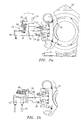
part 50 by blowing air and subsequently continues to cool thepart 50 inside a cooledtube 74 that also removes thepart 50 from the mold. Still further, cooling of thepart 50 is performed in a vertical orientation inside a cooledtube 74. As a result, thepart 50 has improved properties which are beneficial. Using the device of the present invention, time in this vertical orientation is optimized. - Referring now to FIG. 2c, an alternative mechanism can be used to rotate a
head 72 containing only coolingtubes 72. As shown in this figure, thehead 72 may be attached to aframe 64 mounted to one of thecarriers 18 bypin connection 76. Further, a piston-cylinder type ofactuation unit 78 may be connected to theframe 64. Thearm 80 of the actuation unit may be connected to arear portion 82 of thehead 72. As shown in FIG. 2c, thecooling tubes 74 are aligned with core pins 38 and are removing molded articles therefrom. To rotate thehead 72 and move thecooling tubes 74 to a vertical orientation, theactuation unit 78 retractsarm 80 and assumes the substantially vertical position shown in dotted lines in the figure. - Referring now to FIGS. 8a and 8b, a second embodiment of the cooling device of the present invention is illustrated. In this embodiment, blowing
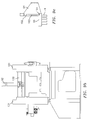
tubes 70 have been omitted. Instead, the cooling device 62' hasadditional cooling tubes 74 so that multi-position cooling can be effected in a manner similar to that illustrated in U.S. Reissue Patent No. 33,237, which is incorporated by reference herein. - As shown in FIG. 8a, the device 62' is mounted in position III on the index
machine turret carriage 18. The device 62' has asingle side frame 84 mounted to one of thecarriers 18 which contains acam track profile 86. Theprofile 86 is followed by acam follower 88 mounted to amovable carrier plate 90 on which are mountedmultiple cooling tubes 74. In a preferred embodiment, the number ofcooling tubes 74 on thecarrier plate 90 is twice the number of core pins 38 on each face of theturret block 16. By providing this number ofcooling tubes 74, the molded parts can be held within thecooling tubes 74 for successive molding cycles, thus extending the cooling times which can be achieved. - An
actuator 92 is mounted to theside frame 84 and has a journaledconnection 94 with thecarrier plate 90 such that when the actuator=srod 96 is extended thecarrier plate 90, following thecam track profile 86, is first translated to move thecarrier plate 90 in a vertical direction and then moved from the vertical plane orientation shown in FIG. 8a to the horizontal plane orientation shown in FIG. 8b. During translation, a first set ofcooling tubes 74 holding molded parts is moved out of alignment with the core pins 38 and a fresh set ofcooling tubes 74 is presented to receive the next set of molded parts. When thecarrier plate 90 is in the position shown in FIG. 8b, theparts 50 can be cooled in a vertical orientation and ejected when ready onto theconveyor 98 below. Theactuator 92 may comprise any suitable actuator known in the art such as piston-cylinder unit. - FIGS. 9a - 9c illustrate an alternative actuation system for moving the cooling device 62' of FIG. 8a so that the
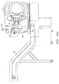
carrier plate 90 moves from a vertical orientation to a horizontal orientation. In this embodiment, theactuator 92 is centrally mounted on abridge 100 connecting support frames 101 on both sides of themachine 10. Theactuator 92, in this arrangement, only effects the vertical positioning of thecarrier plate 90. To effect rotation of thecarrier plate 90 from the vertical position to the horizontal position shown in FIG. 9c, aseparate actuator 102, preferably in the form of a piston-cylinder unit, is provided. Theactuator 102 moves vertically with the carrier plate and when it reaches the end of its vertical travel, theactuator arm 103 is moved to rotate thecarrier plate 90 about thepivot point 105 so that theparts 50 in thecooling tubes 74 is vertically oriented. - FIGS. 10a and 10b illustrate yet another embodiment of an actuation system for the cooling device 62'. In this arrangement, two
cylinders carrier plate 72 containing thecooling tubes 74 is pivotally connected atpivot 108 to theframe 64 which is connected to a support structure on themachine 10. The actuator orcylinder 104 may be attached tocarrier plate 72 in any suitable manner known in the art and is used to translate thecarrier plate 72 withtubes 74 in a vertical direction. This translation may be carried out in any suitable manner known in the art. The actuator orcylinder 106 is connected to thecarrier plate 72 and is used to rotate thecarrier plate 72 aboutpivot point 108 so thattubes 74 assume a vertical orientation. - As can be seen from the foregoing discussion, there has been provided in the embodiments of FIGS. 8 - 10, a lightweight, multi-position cooling carrier plate arrangement for attachment to an index carrier that removes parts horizontally from the mold and cools and ejects them in a vertical orientation, while extending cooling time with multiple tubes.
Claims (25)
- A cooling device (62, 62') for use with an index molding machine (10) having a rotary turret block (16) mounted within support means (18) and at least one mold core (38) on each of at least two faces of said rotary turret block (16), said cooling device (62, 62') comprising:frame moans (64, 84, 101) attached to said rotary turret block support means (18);means (70, 74) for receiving and cooling at least one molded part (50);said receiving and cooling means (74) being mounted to a first surface of a carrier plate (72, 90) connected to said frame means (64, 84, 101); andmeans for moving said carrier plate (72, 90) between a first orientation where said receiving and cooling means (74) is aligned with said at least one molded part (50) and a second orientation where said at least one molded part (50) is being cooled within said receiving and cooling means (74).
- The cooling device according to claim 1, wherein said at least one molded part (50) is vertically oriented while being cooled within said receiving and cooling means (74).
- The cooling device of claim 1 or 2, wherein said receiving and cooling means comprises at least one cooling tube (74) for receiving said at least one molded part and for cooling same by placing an external surface of said at least one molded part (50) in contact with an interior surface of said at least one cooling tube (74).
- The cooling device of claim 3, wherein each said cooling tube (74) has vacuum means for facilitating removal of a respective molded part (50) from at least one mold core pin (38) and for holding said respective molded part (50) within said cooling tube (74).
- The cooling device of at least one of claim 1-4, further comprising:said carrier plate (72) including two surfaces at right angles to each other; andmeans (70) for blowing cooling air onto exterior surfaces of said at least one molded part (50), said blowing means (70) being mounted to a second one of said two surfaces.
- The cooling device of claim 5, wherein said receiving and cooling means comprises at least one cooling tube (74) mounted to said first surface, said at least one cooling tube (74) being oriented substantially perpendicular to said blowing means (70) and wherein said carrier plate (72) is connected to a cross beam (66) attached to said frame (64) means and said moving means comprises means (68) for rotating said cross beam (66) through a rotation of 90 degrees.
- The cooling device of at least one of claims 1-4, wherein said carrier plate (72) is rotatable connected to said frame means (64) and said moving means comprises an actuation unit (78) mounted to said frame means (64) and to a rear surface (82) of said carrier plate (72) for moving said carrier plate (72) between said first and second orientations.
- The cooling device of at least one of claims 1-7, wherein each of said faces has a number of mold cores (38) for carrying molded parts (50) from a molding position to a cooling position and wherein said receiving and cooling means comprises a number of cooling tubes (74) for receiving and cooling said molded parts (50), the number of cooling tubes (74) being at least twice the number of mold cores (38).
- The cooling device of at least one of claims 1-4, further comprising:said frame means (84) containing a cam track profile (86);said carrier plate (72) having a cam follower (88) which engages with said cam track profile (86); andsaid moving means comprises an actuator unit (92) attached to said carrier plate (72) for causing said carrier plate (72) to move along said cam track profile (86) and move from said first orientation to said second orientation.
- The cooling device of at least one of claims 1-4, further comprising:said cooling and receiving means comprising a plurality of cooling tubes (74); andmeans for extending the cooling of said at least one molded part (50), said extending means comprising first actuation means (92, 106) for translating said carrier plate (72, 90) while said carrier plate is in said first orientation between a first position where a first one of said cooling tubes (74) is aligned with a first molded part on a first mold core (38) on a first of said two faces in order to receive same for cooling and a second position where said first one of said cooling tubes (74) is not aligned with any mold core (38) and a second one of said cooling tubes is aligned with a mold core on a second of said two faces for receiving a second molded part.
- The cooling device of claim 10, wherein said moving means comprises a second actuation means (102, 104) for rotating said carrier plate (72, 90) between said first orientation and said second orientation, and wherein said first and second actuation means (92, 106; 102, 104) are connected to said frame means (64, 101).
- An injection molding machine which comprises:a first platen (14) carrying a first mold half (32) having at least one mold cavity (34);a second platen in association with said first platen, said second platen comprising rotatable turret block (16) means rotatable on a central axis (20) of rotation for rotating at least two movable mold halves (26) into alignment with said first mold half (32);each of said movable mold halves (36) having at least one mold core (38) and being movable between a first molding position where it is aligned with said first mold half (32) and a second cooling position where it is not aligned with said first mold half (32);means for moving said rotatable turret block means (16) to bring a first one of said movable mold halves (36) into a mold closed position;means for injecting plastic material into said at least one mold cavity (34) while said first one of said movable mold halves (36) is in said mold closed position and forming at least one molded part (50);said moving means further comprising means for moving said rotatable turret block means (16) and said first one of said movable mold halves (36) to a mold open position where said at least one molded part (50) resides on said at least one mold core (38) on said first one of said movable mold halves (36);means for rotating said rotatable turret block means (16) to cause said first one of said movable mold halves (36) to rotate from said mold open position to said second cooling position and to cause a second one of said movable mold halves (36) to move to said first molding position; andmeans attached to said rotatable turret block means (16) for cooling exterior surfaces of said at least one molded part (50) on said at least one mold core (38) while said first one of said movable mold halves (36) is in said second cooling position.
- The injection molding machine according to claim 12, wherein said cooling means comprises:at least one cooling tube (74) mounted to a first surface of a carrier plate (72, 90) attached to said molding machine; andmeans for rotating said carrier plate (72, 90) between a first position where said at least one cooling tube (74) is aligned with said at least one molded part (50) on said first one of said movable mold halves (36) and a second position wherein said at least one molded part (50) is resident in said at least one cooling tube (74) and is oriented vertically.
- The injection molding machine according to claim 13, wherein:each said cooling tube (74) cools a respective molded part (50) by contact between exterior surfaces of said molded part and interior surfaces of said cooling tube and has vacuum means for holding said respective molded part (50) within said cooling tube (74);said movable mold half (36) includes means for ejecting said at least one molded part (50) into said at least one cooling tube (74); andsaid cooling device further includes means (70) for blowing a cooling fluid onto exterior surfaces of said at least one molded part (50) and said blowing means (70) being mounted to a second surface of said carrier plate (72), said second surface being substantially perpendicular to said first surface.
- The injection molding machine according to claim 14, further comprising said carrier plate (72) being mounted to a rotatable cross beam (66) connected to said injection molding machine and said rotating means comprising means for rotating said cross beam (66) through a 90 degree angle of rotation; and said cooling device comprises at least twice as many cooling tubes (74) as molded parts (50).
- The injection molding machine according to claim 13, wherein said cooling device further comprises:a frame (84) having a cam track profile (86) attached to said machine;a cam follower (88) on said carrier plate (90) for cooperating with said cam track profile (86); andsaid rotating means comprising an actuation unit (92) attached to said carrier plate (90) for causing said carrier plate (90) to move along said cam track profile (86).
- The injection molding machine according to claim 16, wherein said actuation unit (92) translates said carrier plate (90) between a first position where a first cooling tube (74) receives a first molded part (50) from said first one of said movable mold halves (36) and a second position where a second cooling tube (74) receives a second molded part (50) from the second one of said movable mold halves (36) while said first molded part (50) is being cooled within said first cooling tube (74).
- The injection molding machine according to at least one of claims 13-17, wherein said cooling device further comprises:means for translating said carrier plate (72, 90) between a first position where a first cooling tube (74) receives a first molded part (50) from said first one of said movable mold halves (36) and a second position where a second cooling tube (74) receives a second molded part (50) from the second one of said movable mold halves (36) while said first molded part (50) is being cooled within said first cooling tube (74).
- The injection molding machine according to claim 17 or 18, wherein said translating means comprises a first actuation unit (92, 106) connected to a support structure attached to said machine and said rotating means comprises a second actuation unit (102, 104) attached to said support structure.
- A process for forming cooled molded parts comprising the steps of:providing an index molding machine having a first platen (14) carrying a first mold half (32) having at least one mold cavity (34) and a second platen comprising rotatable turret block means (16) rotatable on a central axis (20)of rotation for rotating at least two movable mold halves (36) into alignment with said first mold half (32), each of said movable mold halves (36) having at least one mold core (38);moving said rotatable turret block means (16) to bring a first one of said movable mold halves (36) into a mold closed position with said first mold half (32) and clamping said first one of said movable mold halves (36) and said first mold half (32);injecting molten material into said at least one mold cavity (34) to form a first molded part set of at least one molded part (50);holding said first one of said movable mold halves (36) in said mold closed and clamped position while cooling said first molded part set;moving said rotatable turret block means (16) to a mold open position where said first molded part set is positioned on said at least one mold core (38) on said first one of said movable mold halves (36);rotating said turret block means (16) to bring said first molded part set to a cooling position;providing a cooling device on a carrier plate (72, 90) adjacent said cooling position, said cooling device having at least one cooling tube (74) for receiving said at least one molded part (50) forming said first set;ejecting each said molded part (50) forming said first set into said at least one cooling tube (74);rotating said at least one cooling tube (74) to a position where each said molded part (50) in said first set is in a desired orientation; andcooling each said molded part (50) in said first set while it is in said desired orientation.
- The process according to claim 20, further comprising:moving said rotatable turret block means (16) to bring a second one of said movable mold halves (36) into said mold closed position and clamping said second one of said movable mold halves (36) to said first mold half (32);injecting molten material into said at least one mold cavity (34) to form a second molded part (50) set comprising at least one molded part while said first molded part set is being cooled;holding said second one of said movable mold halves (36) in said mold closed and clamped position while cooling said second molded part set;moving said rotatable turret block means (16) to a mold open position where said second molded part set is positioned on said at least one mold core (38) on said second one of said movable mold halves (36);rotating said turret block means (16) to bring said second molded part set to said cooling position;ejecting said second molded part set into said at least one cooling tube (74);rotating said at least one cooling tube (74) to a position where each molded part (50) in said second set is in said desired orientation; andcooling each said molded part (50) in said second set while it is in said desired orientation.
- The process according to claim 21, further comprising:said cooling device including means (70) for blowing air onto exterior surfaces of said molded parts (50);prior to each said ejecting step blowing air onto each respective set of molded parts while said molded parts (50) are on said mold cores (38) on a respective one of said movable mold halves (36) and thereafter rotating said carrier plate (72, 90) to bring said at least one cooling tube (74) into alignment with said respective set of molded parts (50).
- The process according to claim 22, wherein said carrier plate rotating step comprises rotating said carrier plate (72, 90) 90 degrees, and said step of rotating said at least one cooling tube (74) to bring said molded parts (50) being cooled into said desired orientation also causes said blowing means (70) to be aligned with the next set of molded parts (50) to be cooled.
- The process according to at least one of claims 21-23, further comprising:translating said carrier plate (72, 90) after said first molded part set ejection step to bring a second set of cooling tubes (74) into alignment with said second set of molded parts (50) to be cooled.
- The process according to at least one of claims 21-24, wherein said desired orientation is a vertical orientation.
Applications Claiming Priority (3)
| Application Number | Priority Date | Filing Date | Title |
|---|---|---|---|
| US167669 | 1998-10-07 | ||
| US09/167,669 US6129845A (en) | 1997-12-05 | 1998-10-07 | Catalyst-containing photo-oxidation device, and water treatment system of a semiconductor device fabrication line employing said device |
| US167699 | 1998-10-07 |
Publications (3)
| Publication Number | Publication Date |
|---|---|
| EP0992330A2 true EP0992330A2 (en) | 2000-04-12 |
| EP0992330A3 EP0992330A3 (en) | 2003-01-08 |
| EP0992330A9 EP0992330A9 (en) | 2004-12-22 |
Family
ID=22608298
Family Applications (1)
| Application Number | Title | Priority Date | Filing Date |
|---|---|---|---|
| EP99119167A Withdrawn EP0992330A3 (en) | 1998-10-07 | 1999-10-06 | Cooling device attached to molding machine with rotary turret block |
Country Status (1)
| Country | Link |
|---|---|
| EP (1) | EP0992330A3 (en) |
Cited By (3)
| Publication number | Priority date | Publication date | Assignee | Title |
|---|---|---|---|---|
| WO2005110716A2 (en) * | 2004-05-07 | 2005-11-24 | Graham Packaging Pet Technologies Inc. | Take out and cooling system and method |
| CN115648502A (en) * | 2022-11-16 | 2023-01-31 | 湖南诚路管业科技有限公司 | Energy-saving HDPE water feed pipe rapid cooling equipment |
| CN116533439A (en) * | 2023-07-07 | 2023-08-04 | 常州市中佳塑业有限公司 | Injection molding machine with rotary conveying feeding and discharging mechanism |
Citations (5)
| Publication number | Priority date | Publication date | Assignee | Title |
|---|---|---|---|---|
| US4140464A (en) * | 1977-06-13 | 1979-02-20 | Emhart Industries, Inc. | Machine system for formation of molecularly oriented plastic bottles |
| GB2046657A (en) * | 1979-02-21 | 1980-11-19 | Emhart Ind | Matching Parison Production Rate to Bottle Blow Moulding Rate |
| US4729732A (en) * | 1985-05-14 | 1988-03-08 | Husky Injection Molding Systems Ltd. | Carrying means for holding and cooling a parison |
| US4786455A (en) * | 1981-02-23 | 1988-11-22 | The Continental Group, Inc. | Rotary injection turret and method of utilizing the same in the making of preforms |
| US5728409A (en) * | 1996-03-06 | 1998-03-17 | Husky Injection Molding Systems Ltd. | Turret article molding machine |
-
1999
- 1999-10-06 EP EP99119167A patent/EP0992330A3/en not_active Withdrawn
Patent Citations (5)
| Publication number | Priority date | Publication date | Assignee | Title |
|---|---|---|---|---|
| US4140464A (en) * | 1977-06-13 | 1979-02-20 | Emhart Industries, Inc. | Machine system for formation of molecularly oriented plastic bottles |
| GB2046657A (en) * | 1979-02-21 | 1980-11-19 | Emhart Ind | Matching Parison Production Rate to Bottle Blow Moulding Rate |
| US4786455A (en) * | 1981-02-23 | 1988-11-22 | The Continental Group, Inc. | Rotary injection turret and method of utilizing the same in the making of preforms |
| US4729732A (en) * | 1985-05-14 | 1988-03-08 | Husky Injection Molding Systems Ltd. | Carrying means for holding and cooling a parison |
| US5728409A (en) * | 1996-03-06 | 1998-03-17 | Husky Injection Molding Systems Ltd. | Turret article molding machine |
Cited By (5)
| Publication number | Priority date | Publication date | Assignee | Title |
|---|---|---|---|---|
| WO2005110716A2 (en) * | 2004-05-07 | 2005-11-24 | Graham Packaging Pet Technologies Inc. | Take out and cooling system and method |
| WO2005110716A3 (en) * | 2004-05-07 | 2006-03-16 | Graham Packaging Pet Tech | Take out and cooling system and method |
| US7632089B2 (en) | 2004-05-07 | 2009-12-15 | Graham Packaging Pet Technologies, Inc. | Take out and cooling system and method |
| CN115648502A (en) * | 2022-11-16 | 2023-01-31 | 湖南诚路管业科技有限公司 | Energy-saving HDPE water feed pipe rapid cooling equipment |
| CN116533439A (en) * | 2023-07-07 | 2023-08-04 | 常州市中佳塑业有限公司 | Injection molding machine with rotary conveying feeding and discharging mechanism |
Also Published As
| Publication number | Publication date |
|---|---|
| EP0992330A3 (en) | 2003-01-08 |
Similar Documents
| Publication | Publication Date | Title |
|---|---|---|
| US6059557A (en) | Cooling device attached to index machine | |
| US7056465B2 (en) | Post mold cooling apparatus and method having transverse movement | |
| US6986653B2 (en) | Post mold cooling apparatus and method having transverse movement | |
| CA2516480C (en) | Platen mounted post mold cooling apparatus | |
| US6143225A (en) | Turret cooling block for an index machine | |
| US6663813B2 (en) | Method for cooling molded articles | |
| US4140468A (en) | Plastic bottle forming machine with modular design | |
| EP0001626B1 (en) | Injection blow molding apparatus method | |
| US9381692B2 (en) | Apparatus and method for injection molding and cooling pet preforms | |
| US6113834A (en) | Cooling device attached to index machine | |
| US6848900B2 (en) | Apparatus for handling injection molded preforms | |
| US5744088A (en) | Method and apparatus for manufcturing hollow objects, in particular plastic preforms | |
| US4769205A (en) | In-mold labeling method | |
| EP0992330A2 (en) | Cooling device attached to molding machine with rotary turret block | |
| JP4327463B2 (en) | Mold fixing device |
Legal Events
| Date | Code | Title | Description |
|---|---|---|---|
| PUAI | Public reference made under article 153(3) epc to a published international application that has entered the european phase |
Free format text: ORIGINAL CODE: 0009012 |
|
| AK | Designated contracting states |
Kind code of ref document: A2 Designated state(s): AT BE CH CY DE DK ES FI FR GB GR IE IT LI LU MC NL PT SE |
|
| AX | Request for extension of the european patent |
Free format text: AL;LT;LV;MK;RO;SI |
|
| PUAL | Search report despatched |
Free format text: ORIGINAL CODE: 0009013 |
|
| AK | Designated contracting states |
Kind code of ref document: A3 Designated state(s): AT BE CH CY DE DK ES FI FR GB GR IE IT LI LU MC NL PT SE |
|
| AX | Request for extension of the european patent |
Free format text: AL;LT;LV;MK;RO;SI |
|
| RIC1 | Information provided on ipc code assigned before grant |
Free format text: 7B 29C 35/16 A, 7B 29C 45/04 B, 7B 29C 45/40 B, 7B 29C 45/72 B |
|
| RIN1 | Information on inventor provided before grant (corrected) |
Inventor name: ILMONEN, ROBERT TAYLOR Inventor name: BOURQUE, JACQUES P. Inventor name: GALT, JOHN Inventor name: JACOVICH, WILLIAM J. Inventor name: ING, RONALD |
|
| 17P | Request for examination filed |
Effective date: 20030708 |
|
| AKX | Designation fees paid |
Designated state(s): AT BE CH CY DE DK ES FI FR GB GR IE IT LI LU MC NL PT SE |
|
| 17Q | First examination report despatched |
Effective date: 20061218 |
|
| RAP1 | Party data changed (applicant data changed or rights of an application transferred) |
Owner name: HUSKY INJECTION MOLDING SYSTEMS S.A. |
|
| STAA | Information on the status of an ep patent application or granted ep patent |
Free format text: STATUS: THE APPLICATION HAS BEEN WITHDRAWN |
|
| 18W | Application withdrawn |
Effective date: 20081222 |