CN116209631A - Method and device for stacking flat workpieces - Google Patents
Method and device for stacking flat workpieces Download PDFInfo
- Publication number
- CN116209631A CN116209631A CN202180064504.8A CN202180064504A CN116209631A CN 116209631 A CN116209631 A CN 116209631A CN 202180064504 A CN202180064504 A CN 202180064504A CN 116209631 A CN116209631 A CN 116209631A
- Authority
- CN
- China
- Prior art keywords
- flat
- partition
- conveyor
- workpieces
- stacking
- Prior art date
- Legal status (The legal status is an assumption and is not a legal conclusion. Google has not performed a legal analysis and makes no representation as to the accuracy of the status listed.)
- Pending
Links
- 238000000034 method Methods 0.000 title claims abstract description 38
- 238000005192 partition Methods 0.000 claims abstract description 142
- 238000011144 upstream manufacturing Methods 0.000 claims description 21
- 230000008569 process Effects 0.000 claims description 14
- 238000000926 separation method Methods 0.000 claims description 5
- 230000008859 change Effects 0.000 claims description 2
- 239000010408 film Substances 0.000 description 37
- 239000012788 optical film Substances 0.000 description 28
- 230000005484 gravity Effects 0.000 description 13
- 238000005520 cutting process Methods 0.000 description 11
- 239000000463 material Substances 0.000 description 8
- 239000012790 adhesive layer Substances 0.000 description 7
- 238000003780 insertion Methods 0.000 description 7
- 230000037431 insertion Effects 0.000 description 7
- 239000010410 layer Substances 0.000 description 7
- 230000001681 protective effect Effects 0.000 description 7
- 238000003860 storage Methods 0.000 description 7
- 230000003287 optical effect Effects 0.000 description 6
- 230000001154 acute effect Effects 0.000 description 5
- 230000002093 peripheral effect Effects 0.000 description 5
- 238000000638 solvent extraction Methods 0.000 description 5
- 238000004519 manufacturing process Methods 0.000 description 4
- 239000002184 metal Substances 0.000 description 4
- 229910052751 metal Inorganic materials 0.000 description 4
- 239000011347 resin Substances 0.000 description 4
- 229920005989 resin Polymers 0.000 description 4
- 238000009751 slip forming Methods 0.000 description 4
- 230000015572 biosynthetic process Effects 0.000 description 3
- 230000008878 coupling Effects 0.000 description 3
- 238000010168 coupling process Methods 0.000 description 3
- 238000005859 coupling reaction Methods 0.000 description 3
- 125000006850 spacer group Chemical group 0.000 description 3
- 230000004308 accommodation Effects 0.000 description 2
- 238000009792 diffusion process Methods 0.000 description 2
- 238000009499 grossing Methods 0.000 description 2
- 238000011084 recovery Methods 0.000 description 2
- 239000004925 Acrylic resin Substances 0.000 description 1
- 229920000178 Acrylic resin Polymers 0.000 description 1
- 239000004820 Pressure-sensitive adhesive Substances 0.000 description 1
- 239000012461 cellulose resin Substances 0.000 description 1
- 150000001925 cycloalkenes Chemical class 0.000 description 1
- 230000000994 depressogenic effect Effects 0.000 description 1
- 238000006073 displacement reaction Methods 0.000 description 1
- 230000000694 effects Effects 0.000 description 1
- 230000005611 electricity Effects 0.000 description 1
- -1 for example Substances 0.000 description 1
- 238000007689 inspection Methods 0.000 description 1
- 238000009434 installation Methods 0.000 description 1
- 239000004973 liquid crystal related substance Substances 0.000 description 1
- 239000000314 lubricant Substances 0.000 description 1
- 238000012986 modification Methods 0.000 description 1
- 230000004048 modification Effects 0.000 description 1
- NJPPVKZQTLUDBO-UHFFFAOYSA-N novaluron Chemical compound C1=C(Cl)C(OC(F)(F)C(OC(F)(F)F)F)=CC=C1NC(=O)NC(=O)C1=C(F)C=CC=C1F NJPPVKZQTLUDBO-UHFFFAOYSA-N 0.000 description 1
- 239000004033 plastic Substances 0.000 description 1
- 229920001296 polysiloxane Polymers 0.000 description 1
- 238000003825 pressing Methods 0.000 description 1
- 238000012545 processing Methods 0.000 description 1
- 239000002994 raw material Substances 0.000 description 1
- 239000002893 slag Substances 0.000 description 1
- 230000003068 static effect Effects 0.000 description 1
- 239000000057 synthetic resin Substances 0.000 description 1
- 229920003002 synthetic resin Polymers 0.000 description 1
Images


Classifications
-
- B—PERFORMING OPERATIONS; TRANSPORTING
- B65—CONVEYING; PACKING; STORING; HANDLING THIN OR FILAMENTARY MATERIAL
- B65H—HANDLING THIN OR FILAMENTARY MATERIAL, e.g. SHEETS, WEBS, CABLES
- B65H31/00—Pile receivers
-
- B—PERFORMING OPERATIONS; TRANSPORTING
- B65—CONVEYING; PACKING; STORING; HANDLING THIN OR FILAMENTARY MATERIAL
- B65H—HANDLING THIN OR FILAMENTARY MATERIAL, e.g. SHEETS, WEBS, CABLES
- B65H31/00—Pile receivers
- B65H31/24—Pile receivers multiple or compartmented, e.d. for alternate, programmed, or selective filling
-
- B—PERFORMING OPERATIONS; TRANSPORTING
- B65—CONVEYING; PACKING; STORING; HANDLING THIN OR FILAMENTARY MATERIAL
- B65H—HANDLING THIN OR FILAMENTARY MATERIAL, e.g. SHEETS, WEBS, CABLES
- B65H31/00—Pile receivers
- B65H31/34—Apparatus for squaring-up piled articles
- B65H31/36—Auxiliary devices for contacting each article with a front stop as it is piled
-
- B—PERFORMING OPERATIONS; TRANSPORTING
- B65—CONVEYING; PACKING; STORING; HANDLING THIN OR FILAMENTARY MATERIAL
- B65H—HANDLING THIN OR FILAMENTARY MATERIAL, e.g. SHEETS, WEBS, CABLES
- B65H2405/00—Parts for holding the handled material
- B65H2405/30—Other features of supports for sheets
- B65H2405/33—Compartmented support
- B65H2405/331—Juxtaposed compartments
- B65H2405/3312—Juxtaposed compartments for storing articles vertically or inclined (>45)
Abstract
The present invention relates to a stacking method of flat workpieces capable of stacking and recovering a plurality of flat workpieces that are sequentially conveyed. The method comprises the following steps: a plurality of flat workpieces (1) arranged in a plurality of rows and a plurality of columns are conveyed by a conveyor (3), the flat workpieces (1) are moved to the upper surface (5 a) of a partition (5) arranged outside the conveyor (3), and the flat workpieces (1) are brought into contact with a stopper (7), so that the flat workpieces (1) are dropped into a receiving portion (42) provided between adjacent partitions (5) and stacked.
Description
Technical Field
The present invention relates to a stacking method and a stacking apparatus for transporting a plurality of flat workpieces and sequentially stacking the flat workpieces in a housing portion.
Background
Conventionally, an optical film has been used for image display devices such as liquid crystal display devices and organic EL display devices. Examples of the optical film include a polarizing film including a polarizer, a retardation film, and a light diffusion film. Polarizing films and the like are also used for applications other than image display devices such as polarized sunglasses and light control windows.
Such an optical film is formed into a flat workpiece having a predetermined planar shape so as to be aligned with a screen or the like of the image display device for assembly on the screen or the like. For example, a roll of an optical film raw material (a long strip-shaped optical film or a large sheet of an optical film) is cut by a cutter, whereby a plurality of flat workpieces (an optical film formed into a predetermined planar shape Shan Zhangzhuang) are continuously formed. The continuously formed flat workpieces are conveyed by a conveyor and sequentially and intensively conveyed to the next process.
Prior art literature
Patent literature
Patent document 1: japanese patent laid-open No. 2017-77937
Disclosure of Invention
The system of patent document 1 is functionally preferable because it can smoothly stack and recover flat workpieces. However, the work conveying table having the obliquely extending downstream end edge has a relatively large area, and thus the installation space thereof becomes large. Thus, the system of patent document 1 is limited by the equipment location which must be located in a somewhat wide location.
On the other hand, from the viewpoint of technical diversification, it is also required to smoothly stack the flat workpieces conveyed in sequence in a manner different from patent document 1.
Problems to be solved by the invention
The present invention aims to provide a stacking method of flat workpieces and a stacking device of flat workpieces, wherein the stacking method can stack and recycle a plurality of flat workpieces which are sequentially conveyed.
Means for solving the problems
The stacking method of the flat workpieces comprises the following steps: the flat plate work is sequentially conveyed on a conveying surface of the conveyor in a state that the flat plate work is arranged in a plurality of rows in a width direction and in a plurality of rows in a conveying direction which is a direction orthogonal to the width direction, so that each flat plate work which is protruded to an outer side of the downstream side edge due to the conveying of the conveyor is made to travel while sliding on an upper surface of the partition, and the flat plate work is made to hit the stopper and is made to fall from the upper surface of the partition, and is sequentially stacked in a housing portion between the adjacent partitions.
In a preferred stacking method of the present invention, the flat workpieces are stacked in the housing portion in this order in a state inclined with respect to the horizontal.
In a preferred stacking method of the present invention, after stacking the storage sections in the inclined state, the stacked product is transported to the next step.
In the stacking method of the present invention, after the flat workpiece hits the stopper portion, the flat workpiece rotates to drop from the upper surface of the partition portion and sequentially stack the flat workpiece in the receiving portion.
In the stacking method according to the present invention, the planar shape of the plurality of flat workpieces is a shape having a major axis and a minor axis, and the plurality of flat workpieces are arranged on the conveying surface of the conveyor in a state in which the major axis of the flat workpieces is inclined with respect to the conveying direction.
According to another aspect of the present invention, a stacking apparatus for flat workpieces is provided.
The stacking device for flat workpieces of the present invention comprises: a conveyor that sequentially conveys a plurality of flat workpieces from an upstream side to a downstream side in a conveying direction in a state where the plurality of flat workpieces are arranged in a plurality of rows in a width direction and in a conveying direction which is a direction orthogonal to the width direction; a plurality of partitions disposed outside the downstream side edge of the conveyor in correspondence with the respective rows of the flat plate workpieces, each partition having an upper surface that temporarily supports the flat plate workpieces that are to be projected outside the downstream side edge by conveyance by the conveyor; and a stopper portion disposed on a downstream side of the partition portion, for preventing the flat work from advancing while sliding on an upper surface of the partition portion, and guiding the flat work to a housing portion between the adjacent partition portions.
In a preferred stacking apparatus according to the present invention, each of the adjacent partitions is displaceable so as to change the interval between the partitions.
In the stacking device according to the present invention, a receiving portion extending to one side of each of the partitions is provided below each of the partitions, and the receiving portion is partitioned by the adjacent partition and the receiving portion.
In the stacking device according to the present invention, a right receiving portion and a left receiving portion extending to one side of the partition portion and the opposite side thereof are provided below the partition portions, respectively, and the receiving portion is partitioned by the adjacent partition portions and the right receiving portion and the left receiving portion.
Effects of the invention
According to the stacking method and the stacking apparatus of the flat workpieces of the present invention, a plurality of flat workpieces sequentially conveyed by a conveyor can be efficiently stacked.
Drawings
Fig. 1 is a top view of a planar workpiece.
Fig. 2 is a side view showing an example of layer constitution of a flat workpiece.
Fig. 3 is a side view showing another example of layer constitution of a flat work.
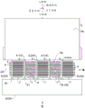
Fig. 4 is a schematic side view of a system incorporating the stacking apparatus of the present invention.
Fig. 5 is a schematic top view of the system.
Fig. 6 is a schematic plan view of the system with the conveyor belt modified.
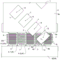
Fig. 7 is a top view of the stacking apparatus of the present invention.
Fig. 8 is a right side view of the stacking device as viewed from the arrow VIII direction of fig. 7.
Fig. 9 is a front view of the stacking apparatus as seen from the arrow IX direction of fig. 7.
Fig. 10 (a) is a top view of a first holding member having a partition, (b) is a right side view of the first holding member, and (c) is a front view of the first holding member.
FIG. 11 is an enlarged cross-sectional view taken along line XI-XI of FIG. 10.
Fig. 12 (a) is a plan view of a second holding member having a partition, (b) is a right side view of the second holding member, and (c) is a front view of the second holding member.
Fig. 13 is an enlarged sectional view taken along line XIII-XIII of fig. 12.
Fig. 14 is a plan view showing a state in which receiving portions of adjacent holding members overlap.
FIG. 15 is an enlarged cross-sectional view taken along line XV-XV of FIG. 14.
Fig. 16 is a plan view showing a flat workpiece conveyed by a conveyor.
Fig. 17 is a plan view showing a state where the flat workpiece is transferred to the upper surface of the partition.
Fig. 18 (a) is a partially omitted side view as seen from the direction of arrow XVIII in fig. 17, and (b) is a partially omitted side view showing a state in which the flat workpiece travels while sliding on the upper surface of the partition.
Fig. 19 is a plan view showing a state where the flat workpiece hits the stopper portion.
Fig. 20 is a front view showing a state in which the flat workpiece enters the housing portion.
Fig. 21 is a front view showing a state in which a plurality of flat workpieces are stacked in the housing portion.
Fig. 22 (a) is a front view showing a state in which the interval between the holding members including the partition is enlarged and the stacked object is placed on the receiving portion, and (b) is a plan view thereof.
Fig. 23 is a plan view showing a state in which flat workpieces are stacked using the stacking apparatus of the second embodiment.
Fig. 24 is a plan view showing a state in which the flat workpiece falls into the housing portion in the stacking apparatus.
Fig. 25 is a front view showing a state in which the flat workpiece enters the housing portion.
Fig. 26 (a) is a plan view of the holding member of the third embodiment, and (b) is a front view of the holding member.
Fig. 27 is a front view showing a state in which a plurality of holding members of the third embodiment are arranged in the width direction.
Fig. 28 is a right side view of a stacking device having a holding member of the fourth embodiment.
Fig. 29 is a right side view of a stacking device having a temporary bottom of the fifth embodiment.
Fig. 30 is a plan view showing a flat workpiece of various plan view shapes.
Detailed Description
In the present specification, "planar view" refers to a surface of an object such as a flat workpiece viewed from the vertical direction, and "planar view" refers to a shape of an object when the surface of an object such as a flat workpiece is viewed from the vertical direction, and the drawings. In the present specification, a "top view" is a view from above toward below, a "side view" is a view from one side in the width direction toward the opposite side, and a "front view" is a view from the downstream side toward the upstream side in the conveying direction.
In the present specification, the expression "substantially" is meant to include the scope allowed in the technical field of the present invention. In the present specification, when numerical ranges such as a plurality of lower limit values or higher and a plurality of lower limit values or lower limit values are described, an arbitrary lower limit value and an arbitrary upper limit value may be selected, and a numerical range of "an arbitrary lower limit value or higher and an arbitrary upper limit value or lower" may be set.
[ Flat workpiece ]
Fig. 1 shows a top view of a flat workpiece.
The planar shape of the flat workpiece 1 is not particularly limited, and examples thereof include a substantially rectangular shape (a substantially rectangular shape, or a substantially square shape), a substantially polygonal shape such as a substantially triangular shape, a substantially hexagonal shape, a substantially circular shape, a substantially elliptical shape, and a different shape in which these shapes are combined. The "substantially" of the substantially rectangular shape, the substantially triangular shape, and the substantially polygonal shape includes, for example, a shape in which corners are chamfered, a shape in which a part of sides is slightly bulged or depressed, a shape in which sides are slightly curved, and the like. The "substantially" of the substantially circular shape and the substantially elliptical shape includes, for example, a shape in which a part of the circumference is slightly raised or recessed, a shape in which a part of the circumference is slightly formed in a straight line or a diagonal line, and the like.
Fig. 1 illustrates a flat workpiece having a substantially rectangular shape in a plan view. The substantially rectangular shape is a top view shape having a long side (side along the long axis) and a short side (side along the short axis). In fig. 1, a substantially rectangular flat workpiece is shown in which four corners of the rectangle are chamfered, but the corners may be right angles.
The flat workpiece is obtained from an arbitrary web (web).
The type of the flat workpiece (and the web that is the source of the flat workpiece) is not particularly limited, and examples thereof include an arbitrary synthetic resin film, an arbitrary plastic plate, an arbitrary metal thin plate, and a laminated plate in which 2 or more arbitrary layers are laminated. For example, in the present invention, a flat workpiece containing an optical film (and a web containing an optical film) is used. The flat workpiece including the optical film may be constituted by only the optical film, or may have the optical film and a component other than the optical film.
Fig. 2 is a configuration example of a flat workpiece including an optical film, and fig. 3 is another configuration example of a flat workpiece including an optical film.
Referring to fig. 2, the flat workpiece 1 includes an optical film 11, a separator 13, and an adhesive layer 12 interposed between the optical film 11 and the separator 13 to bond the two films 11 and 13. The adhesive layer 12 is firmly adhered to the optical film 11, and is peelably adhered to the separation film 13. The separation film 13 can be peeled off at the interface with the adhesive layer 12. When using the flat work 1, the separation film 13 is generally peeled off and removed. The flat workpiece 1 may not have the adhesive layer 12 and the separator 13.
The optical film 11 includes an optical functional film. Examples of the optical functional film include a polarizer, a retardation film, a light diffusion film, a brightness enhancement film, an antiglare film, and a light reflection film. A polarizer is a film having the following properties: light (polarized light) vibrating in a specific one direction is transmitted, and light vibrating in other directions is blocked. The retardation film is a film showing optical anisotropy, and typically includes a stretched film of an acrylic resin, a cycloolefin resin, a cellulose resin, or the like. The optical film 11 may include a protective film. The protective film is laminated for the purpose of protecting the optical functional film. The protective film may typically be a colorless transparent film.
The optical film 11 of the flat workpiece 1 illustrated in fig. 2 has a first protective film 111, a polarizer 112, and a second protective film 113 in this order from the bottom of the drawing. By bonding the films 111 to 113 to each other, one laminated film (optical film 11) is constituted.
Referring to fig. 3, another flat work 1 has a phase difference film 115 as the optical film 11. Further, a surface protective film 16 is laminated on the surface of the optical film 11 (the surface of the retardation film 115) via an adhesive layer 17. The surface protective film 16 may be peeled off from the surface of the optical film 11 (the retardation film 115) with the pressure-sensitive adhesive layer 17, for example. In fig. 3, the adhesive layer 12 and the separator 13 are adhered to the back surface of the optical film 11, but the adhesive layer 12 and the separator 13 may not be provided. The planar work 1 including the optical film 11 is not limited to the layer configuration of fig. 2 and 3, and various modifications are possible. For example, the flat workpiece 1 may include 2 or more layers of optical functional films, or may be composed of only 1 layer of optical functional films.
[ overview of System of Stacking apparatus including Flat-plate workpieces ]
Fig. 4 and 5 show a system comprising a stacking device of the present invention. The system illustrated in this figure is at least capable of performing stacking, reclaiming and routing of flat workpieces from a web to a next process.
Referring to fig. 4 and 5, the system has: a work manufacturing area Z1 for manufacturing a flat work; a work conveying area Z2 that conveys the flat work 1 obtained in the work manufacturing area Z1 to the work stacking area Z3; a work stacking area Z3 in which the flat work 1 is stacked and recovered; a stacked object conveying area Z4 for conveying the stacked object 100 of the flat plate workpieces 1 stacked in the workpiece stacking area Z3 to the next process; and a next process zone Z5 for performing an arbitrary process on the stack 100.
In the work manufacturing area Z1, a work forming device D1 for forming the flat work 1 is provided, and the work forming device D1 includes a conveyor 26 for conveying the flat work 1 to the downstream side. Hereinafter, this conveyor 26 is referred to as "upstream-side conveyor 26". The upstream conveyor 26 has, for example, an endless belt and is rotated by rollers. The upstream conveyor 26 transfers the formed flat workpiece 1 to a conveyor described later. The work forming device D1 forms a flat work 1 from the web 180. The workpiece forming apparatus D1 is, for example, a cutting apparatus. The cutting device (workpiece forming device D1) includes: a cutter 21 for cutting out the flat workpiece 1 from the web 180; a blade receiving sheet 22 for receiving the blade edge of the cutter blade 21; and a pedestal 23 disposed on the back surface of the blade receiving sheet 22. The blade receiving sheet 22 is endless and rotated by a roller. By pressing the cutting blade 21 against the long strip-shaped web 180 sent from the upstream side, the web 180 is cut, and a plurality of flat workpieces 1 can be continuously formed. In addition, at least both lateral portions of the web 180 in the width direction are generally recovered as cutting residues 182 (so-called slag removal). The direction of conveyance of the web 180 and the direction of recovery of the cutting residue 182 are shown by arrows. The web 180 (and the formed flat workpiece 1) are films including, for example, optical films, as described above. In the illustrated example, a cutting pattern generated only at both side portions of the cutting residual portion 182 is illustrated. In this pattern, a plurality of flat workpieces 1 having the gaps between adjacent flat workpieces 1 substantially equal to the blade thickness of the cutting blade 21 can be obtained. The web 180 may be cut in a cutting pattern that generates a cutting residue between the adjacent flat workpieces 1. In the case of this pattern, a plurality of flat workpieces 1 whose gaps between adjacent flat workpieces 1 are sufficiently larger than the knife thickness can be obtained.
A conveyor 3 for conveying the flat workpiece 1 from the upstream side to the downstream side is provided in the workpiece conveying zone Z2. The conveyor 3 sequentially conveys the plurality of flat workpieces 1 from the upstream side to the downstream side.
Here, the conveyance direction is a direction orthogonal to the width direction in a plan view. The downstream side is the opposite side to the upstream side. The downstream side refers to the side on which the flat work 1 is conveyed.
The flat workpiece 1 is conveyed downstream by the conveyor 3 in a state of being multiple rows in the width direction and being multiple rows in the conveying direction. The number of columns of the flat work 1 is not particularly limited, but is 2 or more columns, preferably 3 or more columns. In fig. 5, for convenience, a case is illustrated in which the flat work 1 is transported by forming 5 rows from the web 180 and arranging the flat work 1 in 5 rows in the width direction. The number of columns is the number of flat workpieces 1 arranged in the width direction.
Fig. 5 illustrates a case where a flat workpiece 1 having a substantially rectangular shape (substantially rectangular shape) in plan view is formed by the workpiece forming apparatus D1. However, the formed flat workpiece 1 is not limited to a substantially rectangular shape (substantially rectangular shape).
Fig. 5 illustrates a case where the flat workpiece 1 having a substantially rectangular shape in plan view is conveyed in a state where 1 side (for example, a side along the long axis) is substantially parallel to the conveying direction. However, the present invention is not limited to this, and the flat workpiece 1 may be conveyed in a state in which 1 side (for example, a side along the long axis) is inclined with respect to the conveying direction. With respect to the conveying direction is meant that the inclination is not substantially parallel and substantially right angle. The substantially parallel refers not only to strict parallelism but also includes an error range. For example, the substantial parallelism is within a range of strictly parallel.+ -. 5 degrees, preferably within a range of strictly parallel.+ -. 3 degrees. The substantially right angle refers not only to a strict right angle but also includes an error range. For example, the substantially right angle is within a range of strictly right angle.+ -. 5 degrees, preferably within a range of strictly right angle.+ -. 3 degrees.
The conveyor 3 has a conveying surface 3a on which the flat workpiece 1 is placed and conveyed. The conveyor 3 has, for example, an endless belt and is rotated by rollers. The upper surface of the belt constitutes the conveying surface 3a. In fig. 5, a belt-shaped belt is used as the belt. As the belt of the conveyor 3, a linear belt 32 may be used as shown in fig. 6. The linear belts 32 are provided in plural at predetermined intervals (intervals of such an extent that the flat workpiece 1 does not fall) in the conveying direction. When the linear belt 32 is used, the conveying surface 3a of the conveyor 3 is formed by connecting the upper surfaces of the plurality of linear belts 32.
The peripheral speed of the conveyor 3 is set to be the same as or faster than the peripheral speed of the upstream side conveyor 26. In the example of the figure, the peripheral speed of the conveyor 3 is faster than that of the upstream side conveyor 26. Thus, the flat workpiece 1 moving from the upstream side conveyor 26 to the conveyor 3 is rapidly conveyed to the downstream side. Therefore, the line space of the flat workpiece 1 on the way conveyed by the upstream conveyor 26 becomes dense, but the line space of the flat workpiece 1 on the way conveyed by the conveyor 3 becomes relatively large. The faster the peripheral speed of the conveyor 3, the larger the inter-line of the flat workpiece 1 conveyed by the conveyor 3.
A stacking device D3 for the flat workpieces 1 is provided in the workpiece stacking area Z3. The stacking device D3 is disposed outside the downstream side edge 3b of the conveyor 3. The stacking device D3 has a holding member 4 that holds the stacked object 100. The stack 100 is formed by stacking a plurality of flat workpieces 1 in the thickness direction. The details of the stacking device D3 will be described later.
A conveying device D4 for moving the holding member 4 of the stacking device D3 is provided in the stacking object conveying area Z4. The conveyor D4 connects at least the workpiece stacking area Z3 and the next process area Z5, and is, for example, annular (endless) in a plan view as shown in fig. 5. The conveying device D4 includes: a passage portion 9 including a work stacking region Z3 and a next process region Z5 and arranged in a ring shape in a plan view; and a plurality of movable bodies (not shown) provided movably in the passage portion 9. The holding member 4 on which the stacked object 100 (the plurality of flat workpieces 1) is placed is moved to the next process zone Z5 by the conveyor D4, and the stacked object 100 is taken out in the next process zone Z5. The emptied holding part 4 is again moved by the conveyor D4 to the workpiece stacking zone Z3, whereupon the flat workpieces 1 are again stacked on the holding part 4. By repeating this operation, a series of operations for stacking, collecting and conveying the flat workpieces 1 continuously manufactured from the web 180 to the next step are performed. In fig. 5 and 6, the movement of the holding member 4 is indicated by an arrow. In fig. 5 and 6, the holding members 4 in five groups 1 are shown as being disposed in 3 places in the conveying device D4 in a dispersed manner, but the number of the holding members 4 is not limited to this. In practice, a plurality of holding members 4 are attached to the conveyor D4.
In the present invention, each device, and the components and the operations of the components constituting each device are naturally controlled by a control unit (not shown) including a computer.
The next process zone Z5 is a zone in which arbitrary processing is performed on the stack 100 or each of the flat workpieces 1 constituting the stack 100. As the next step, an inspection product of the flat workpiece 1, a case of the stacked object 100, and the like can be cited. Reference numeral D5 denotes a work table or the like for the next process.
< first embodiment >, first embodiment
[ Stacking device for Flat-plate workpieces ]
Fig. 7 is a top view of the stacking device D3, fig. 8 is a right side view seen from the arrow VIII direction of fig. 7, and fig. 9 is a front view seen from the arrow IX direction of fig. 7. In each figure, the upstream side of the conveyor 3 is omitted. In fig. 7, the driving devices 72 and 82 of the stopper 7 and the temporary bottom 8 are not shown, and in fig. 9, the conveyor 3 and the conveyor D4 are not shown.
Referring to fig. 7 to 9, a holding member 4 having a partition 5 is disposed outside the downstream side edge 3b of the conveyor 3. The holding member 4 includes a partition 5 and a receiving portion 6 provided below the partition 5. The receiving portion 6 is a portion on which the stack 100 is placed. The receiving portion 6 extends to one side (width direction side) of the partition portion 5. The holding member 4 having the receiving portion 6 is formed in a substantially L-shape in a front view.
The partition 5 (holding member 4) is provided at least in correspondence with each row of the flat workpiece 1 conveyed by the conveyor 3. The adjacent partition 5 divides the housing portion 42 of the stacked flat work 1, and the housing portion 42 is preferably divided by the adjacent partition 5 and the receiving portion 6 between the partitions 5. The housing portion 42 is a space for housing the stacked object 100. The minimum number of the partitions 5 (holding members 4) arranged outside the downstream side edge 3b of the conveyor 3 is the number of columns of the flat workpieces 1. In order to reliably form the accommodating portion 42 in which the flat plate workpieces 1 are stacked by the adjacent partition portions 5, it is preferable that the number of the column +1 of the flat plate workpieces 1 (the holding member 4 having the partition portions 5) be arranged outside the downstream side edge 3b of the conveyor 3 at intervals in the width direction. In fig. 7 to 9, a case in which the flat workpiece 1 of 4 rows is conveyed by the conveyor 3 is illustrated, and therefore, five partitions 5 (holding members 4) are arranged at the downstream side edge 3b of the conveyor 3. However, as described above, the number of columns of the flat workpiece 1 is not limited. The number of the partitions 5 (holding members 4) disposed outside the downstream side edge 3b of the conveyor 3 is appropriately set according to the number of columns of the flat workpieces 1.
The plurality of holding members 4 arranged in the width direction are each independently fixed to a moving body (not shown) of the conveying device D4 via the coupling portion 91. A moving body, not shown, is provided in the passage 9 of the conveyor D4. The movable body can stop at an arbitrary position of the passage portion 9 and can move at an arbitrary speed along the passage portion 9. Thus, the plurality of holding members 4 are individually and movably attached to the passage portion 9 via the movable body. The passage 9 is fixed to a place where it is installed (a frame of the device, etc.). The plurality of holding members 4 having the partition 5 can be displaced in the width direction independently of each other by the moving body. The displacement is a position where the position is specified to be at an arbitrary position and stopped, and the position where the position is stopped is arbitrarily changed. That is, each of the partition portions 5 (holding members 4) can be stopped at a predetermined position independently and can be moved along the passage portion 9 at a predetermined speed. Therefore, the interval (interval in the width direction) between the adjacent partition portions 5 (holding members 4) can be arbitrarily changed, and the interval can be appropriately set at the time of stacking the flat plate workpieces 1, at the time of conveying the stacked object 100, and the like.
The number of the partitions 5 (holding members 4) attached to the conveyor D4 is not limited to the number of columns +1 of the flat work 1, but in practice, the partitions 5 (holding members 4) far exceeding the number are independently attached to the conveyor D4.
Each partition 5 has an upper surface 5a that temporarily supports the flat workpiece 1 that protrudes outward from the downstream side edge 3b due to conveyance by the conveyor 3. The upper surface 5a of the partition 5 is flat. The upper surface 5a of the partition 5 may be inclined with respect to the horizontal, but is preferably horizontal. The respective partitions 5 are arranged such that the upper surfaces 5a of the respective partitions 5 are in the same plane as the conveying surface 3a of the conveyor 3 or slightly below the conveying surface 3 a. In the example shown in the drawing, the upper surface 5a of each partition 5 is located slightly below the conveying surface 3a of the conveyor 3 (see fig. 8). The upper surface 5a is positioned below, so that the flat workpiece 1 is smoothly transferred from the conveyor 3 to the upper surface 5a of the partition 5 and easily falls down to the housing 42 by gravity.
Specifically, in a side view shown in fig. 8, the partition 5 includes: an upper portion 51 having an upper surface 5a extending in the conveying direction; and a side wall portion extending in the up-down direction. The upper surface 5a of the partition 5 may be smoothed, if necessary. As the smoothing treatment, there are a method of applying a lubricant such as silicone to the upper surface 5a of the partition 5, a method of adhering a sliding tape (a tape provided on the surface) to the partition 5, and the like. In the illustrated example, the slide tape 56 is adhered to the partitioning portion 5, in which case the upper surface of the tape 56 constitutes the upper surface 5a of the partitioning portion 5. By smoothing the upper surface 5a of the partition 5, the flat workpiece 1 is moved while smoothly sliding on the upper surface 5a. It is preferable to use a sliding tape 56 having conductivity. By using the slide tape 56 having conductivity, generation of static electricity can be prevented. The side wall portion may be plate-shaped. In order to protrude the temporary bottom 8 described later above the receiving portion 6, the side wall portion is constituted by a plurality of rod-like portions 52 in the example shown in the figure. The upper parts of the plurality of rod-shaped parts 52 are connected to the upper part 51, respectively, and the receiving parts 6 are connected to the lower parts of the plurality of rod-shaped parts 52, respectively. The plurality of rod-shaped portions 52 are connected to the upper portion 51 with gaps 52c therebetween. The plurality of rod-like portions 52 have gaps 52c and are continuous, whereby the plurality of rod-like portions 52 constitute walls.
The plurality of holding members 4 may be identical or different. In the example shown in the figure, two types of holding members 4 different in receiving portion 6 are alternately arranged in the width direction. Hereinafter, in the case where it is necessary to distinguish between the two holding members, one of them is referred to as "first holding member 4-1", the other is referred to as "second holding member 4-2", and both are generally referred to as "holding member 4".
Fig. 10 and 11 show the first holding member 4-1.
The first holding member 4-1 includes a partition 5 and a receiving portion 6 provided below the partition 5. The receiving portion 6 of the first holding member 4-1 is referred to as "first receiving portion 6-1". The partition 5 has: an upper portion 51 having an upper surface 5a that has been smoothed as described above; and a side wall portion (a plurality of rod-like portions 52) constituted by the plurality of rod-like portions 52. The first receiving portion 6-1 is provided in plural numbers and is composed of rod-shaped members. The plurality of first receiving portions 6-1 are arranged with gaps in series so that the plurality of first receiving portions 6-1 constitute a receiving table. As shown in fig. 10 b, the plurality of first receiving portions 6-1 are arranged at the same height position (horizontal position) as each other. The height positions of the plurality of first receiving portions 6-1 are not limited to the same height, and the first receiving portion 6-1 on the left side of the drawing sheet shown in fig. 10 (b) may be lower than the first receiving portion 6-1 on the right side of the drawing sheet.
The plurality of first receiving portions 6-1 are provided to extend from one side in the width direction of the plurality of rod-like portions 52. The base of the first receiving portion 6-1 is connected to the lower portion of the rod-shaped portion 52, and the tip end portion (the end portion on the opposite side to the base) of the first receiving portion 6-1 is set as a free end. The outer diameter of the first receiving portion 6-1 is reduced toward the tip end portion thereof so as to be able to be reliably inserted into an insertion hole 66 of the second receiving portion 6-2 described later. The length (length in the extending direction) of the first receiving portion 6-1 is not particularly limited as long as it is not less than a level at which the stacked object 100 is placed and does not naturally fall.
The first receiving portion 6-1 may extend at right angles to the partition portion 5 (the side wall portion constituted by the rod-like portion 52). Alternatively, in order to prevent the stack 100 from inadvertently falling down when the stack 100 is conveyed to the next process zone Z5, the upper surface of the first receiving portion 6-1 may extend at an acute angle with respect to the partition portion 5 (the rod-like portion 52). That is, the first receiving portion 6-1 may be inclined with respect to the partition portion 5 such that an angle α formed between the upper surface of the first receiving portion 6-1 and the side surface of the partition portion 5 (the side wall portion constituted by the rod-like portion 52) is an acute angle. In this case, the tip end portion of the first receiving portion 6-1 is located above the base portion of the first receiving portion 6-1. The angle α is not particularly limited, but if it is too close to 90 degrees, it is not substantially right-angled, and if it is too large, it is not possible to stack a plurality of flat workpieces 1. From this viewpoint, the angle α is, for example, more than 0 degrees and 20 degrees or less, and further more than 0 degrees and 5 degrees or less.
Fig. 12 and 13 show the second holding member 4-2.
The second holding member 4-2 has a partition 5 and a receiving portion 6 provided below the partition 5, similarly to the first holding member 4-1. The receiving portion 6 of the second holding member 4-2 is referred to as "second receiving portion 6-2". The partition 5 has an upper portion 51 and a side wall portion (a plurality of rod-like portions 52). It is preferable that the partition 5 of the second holding member 4-2 has the same constitution as the partition 5 of the first holding member 4-1.
The second receiving portion 6-2 is provided in plural and is composed of rod-like members. The plurality of second receiving portions 6-2 are arranged in series with gaps therebetween so that the plurality of second receiving portions 6-2 constitute a receiving table. As shown in fig. 12 b, the plurality of second receiving portions 6-2 are arranged at the same height position (horizontal position). The height positions of the plurality of second receiving portions 6-2 are not limited to the same height, and the second receiving portion 6-2 on the left side of the drawing sheet shown in fig. 12 (b) may be lower than the second receiving portion 6-2 on the right side of the drawing sheet. The plurality of second receiving portions 6-2 are provided so as to extend from the lower side of the plurality of rod-like portions 52 to one side in the width direction.
The second receiving portion 6-2 has an insertion space 64 in the extending direction thereof into which the first receiving portion 6-1 is inserted. For example, the second receiving portion 6-2 is formed of an elongated rod that is continuous in a U-shape in the direction in which it extends (the second receiving portion 6-2 is formed of a tube with its upper surface removed). The base of the second receiving portion 6-2 is connected to the lower portion of the rod-shaped portion 52, and the tip end portion (the end portion on the opposite side to the base) of the second receiving portion 6-2 is set as a free end. An insertion hole 66 is opened below the rod-like portion 52 so that the first receiving portion 6-1 can be inserted. The length (length in the extending direction) of the second receiving portion 6-2 is not particularly limited as long as it is not less than a level at which the stacked object 100 is placed and does not naturally fall.
The second receiving portion 6-2 may extend at right angles to the partition portion 5 (the rod-like portion 52). Alternatively, in order to prevent the stack 100 from inadvertently falling down when the stack 100 is conveyed to the next process zone Z5, the upper surface of the second receiving portion 6-2 may extend at an acute angle with respect to the partition portion 5 (the rod-like portion 52) like the first receiving portion 6-1. The angle α of the second receiving unit 6-2 is, for example, more than 0 degrees and 20 degrees or less, and more preferably more than 0 degrees and 5 degrees or less, similar to the angle α of the first receiving unit 6-1.
The first holding members 4-1 and the second holding members 4-2 are alternately arranged in the width direction. The adjacent first holding member 4-1 and second holding member 4-2 can overlap the first receiving portion 6-1 and second receiving portion 6-2.
Specifically, as shown in fig. 14 and 15, each holding member 4 is moved so that the interval between adjacent holding members 4 becomes smaller. At this time, the first receiving portion 6-1 passes through the insertion hole 66 of the second holding member 4-2 and enters the insertion space 64 of the second receiving portion 6-2.
In the present invention, the receiving portions 6 of the adjacent holding members 4 may be configured identically. However, when the receiving portions 6 are configured in the same manner, if the adjacent holding members 4 are brought close to each other, the distal end portion of the receiving portion 6 of one holding member 4 interferes with the base portion of the receiving portion 6 of the other partition 5. Therefore, when the receiving portions 6 are configured identically, the minimum value of the interval of the holding members 4 (the partition portions 5) becomes the length of the receiving portion 6. In this regard, when the first holding members 4-1 and the second holding members 4-2 are alternately arranged in the width direction, the first receiving portion 6-1 enters the insertion space 64 of the second receiving portion 6-2 as described above, and the first receiving portion 6-1 and the second receiving portion 6-2 overlap without interference. Therefore, the adjacent holding members 4 may be brought close to each other, and the interval between the holding members 4 (the partition 5) may be smaller than the length of the receiving portion 6. As described above, by alternately disposing the first holding members 4-1 and the second holding members 4-2, which do not interfere with each other in the receiving portion 6, as shown in fig. 1 and 15, a plurality of holding members 4 can be collectively disposed.
The material forming the holding member 4 (first and second holding members 4-1, 4-2) is not particularly limited. The holding member 4 is formed of a material having excellent strength, such as metal or hard resin.
Referring to fig. 7 to 9, the stacking device D3 has a stopper 7. The stopper 7 is disposed downstream of the partition 5. The stopper 7 is provided to prevent the flat workpiece 1 that moves forward while sliding on the upper surface 5a of the partition 5. The stoppers 7 are provided between at least adjacent partitions 5, respectively. In the illustrated example, the same number of stoppers 7 as the number of holding members 4 arranged outside the downstream side edge 3b of the conveyor 3 is provided. The stopper 7 is configured not to contact the partition 5. For example, the stopper portions 7 are respectively arranged in the middle of the adjacent partition portions.
As shown in fig. 8, the stopper portion 7 may be formed so as to intersect at least the same plane as the upper surface 5a of the partition portion 5. For example, the stopper 7 is formed of a plate-like body. The stopper 7 formed of a plate-like body includes a portion intersecting with the same plane as the upper surface 5a of the partition 5, and extends upward and downward from the portion.
In order to prevent the flat work pieces 1 stacked in the receiving portion 42 from falling off from the downstream side, the stopper portion 7 preferably extends to the vicinity of the receiving portion 6 as shown in fig. 8. In the example of the figure, the stopper 7 extends to such an extent that the lower end 7d of the stopper 7 is located slightly above the socket 6. The width-direction length of the stopper portion 7 is not particularly limited, and is preferably not in contact with the partition portion 5.
The material forming the stopper 7 is not particularly limited. The stopper 7 is formed of a material having excellent strength, such as metal or hard resin.
Each stopper 7 is movable in the up-down direction. For example, each stopper 7 is attached to the driving device 72 via the coupling portion 71. The driving device 72 is fixed to a place where it is installed (a frame of the device, etc.). When stacking the flat plate workpieces 1, each stopper portion 7 is arranged to intersect the same plane as the upper surface 5a of the partition portion 5. When the holding member 4 is moved, the stopper portions 7 are moved upward by the driving device 72 so that the holding member 4 does not interfere with the stopper portions 7. For example, each stopper 7 is retracted above the upper surface 5a of the partition 5 so as not to intersect the upper surface 5a of the partition 5.
The driving device may be set so that each stopper portion 7 can be moved in the conveying direction, if necessary. The thick arrow in fig. 8 indicates the moving direction of the stopper 7. Depending on the planar shape and size of the flat workpiece 1, the flat workpiece 1 that advances on the upper surface 5a of the partition 5 may not touch the stopper 7. As long as the stopper 7 can move to the downstream side and the upstream side in the conveying direction, the position of the stopper 7 can be made to be close to the downstream side edge 3b of the conveyor 3 or to be away from the downstream side edge 3b. The position of the stopper 7 is appropriately adjusted according to the planar shape and size of the flat workpiece 1, so that the traveling flat workpiece 1 can reliably contact the stopper 7.
The driving device may be set so that each stopper portion 7 can be moved in the width direction, as needed. The stopper portions 7 can be displaced in the width direction, and the width direction positions of the stopper portions 7 can be appropriately adjusted in accordance with the intervals between the adjacent partition portions 5.
Furthermore, the stacking device D3 has a temporary bottom 8 that can move up and down. The temporary bottom 8 functions as a receiving base for temporarily supporting the flat workpiece 1 dropped into the receiving portion 42.
The temporary bottom 8 is provided so as to be able to enter the housing 42 and exit from the housing 42. For example, the temporary bottom 8 is formed of a plate-like body (or may be a rod-like body) that can enter the gap 52c of the rod-like portion 52 of the holding member 4. In the illustrated example, the temporary bottom 8 is constituted by a plurality of plate-like bodies that enter the gaps 52c of all the rod-like portions 52. The formation material of the temporary bottom 8 is not particularly limited. The temporary bottom 8 is formed of a material having excellent strength, such as metal or hard resin. The upper end 8a of the temporary bottom 8 may be flat, but is preferably arc-shaped as shown in fig. 8 from the viewpoint of preventing damage to the dropped flat work 1. The upper end 8a of the temporary bottom 8 may be formed of a buffer material such as rubber, or a buffer material (not shown) such as rubber may be provided on the upper end 8a of the temporary bottom 8.
The plurality of temporary bottoms 8 may also be located at the same height position. That is, the plurality of temporary bottoms 8 may be arranged such that a virtual line connecting the upper ends 8a of the temporary bottoms 8 is horizontal in a side view. Alternatively, as shown in fig. 8, the plurality of temporary bottoms 8 are preferably gradually lowered toward the stopper 7 side (downstream side). That is, it is preferable that the plurality of temporary bottoms 8 are inclined with respect to a virtual line connecting the upper ends 8a of the temporary bottoms 8 in a side view. By tilting the upper end portions 8a of the temporary bottoms toward the stopper 7, the flat workpiece 1 placed on the upper end portions 8a of the temporary bottoms 8, which falls down to the receiving portion 42, moves toward the stopper 7 in accordance with the tilting. The moved flat work 1 hits the stopper 7 and stops, and thus the flat work 1 is stacked in a vertically aligned state. The degree of the inclination is not particularly limited, but if too small, the flat workpiece 1 is difficult to move toward the stopper 7 side. The inclination angle β of the upper end 8a of the temporary bottom 8 is, for example, 5 degrees to 20 degrees, preferably 7 degrees to 15 degrees. As shown in fig. 8, the inclination angle β is an angle between a virtual line connecting the upper ends 8a of the temporary bottoms 8 and a horizontal plane.
The temporary bottom 8 may be provided for each of the holding members 4 so as to be able to enter and exit the storage portions 42 of the plurality of holding members 4 independently of each other. Alternatively, the temporary bottom 8 may be configured to be capable of simultaneously entering and exiting the storage portions 42 of the plurality of holding members 4. In the illustrated example, the temporary bottom 8 can simultaneously enter and exit the storage portions 42 of the plurality of holding members 4 disposed outside the downstream side edge 3b of the conveyor 3. In this case, the plate-like body constituting the temporary bottom portion 8 is elongated so as to intersect each holding member 4 and extend in the width direction (see fig. 9).
The temporary bottom 8 is attached to the driving device 82 via the coupling portion 81 so as to be movable in the up-down direction. The driving device 82 is fixed to the place where it is installed (frame of device, etc.). When stacking the flat workpieces 1, the temporary bottom 8 enters the gap 52c of the adjacent rod-shaped portion 52, and protrudes above the receiving portion 6 of the holding member 4 (see fig. 8 and 9).
[ method of stacking Flat workpieces ]
Next, the order of stacking and recovering the flat workpieces 1 will be described.
The stacking method of the flat workpieces 1 according to the present invention is performed using a stacking device D3, wherein the stacking device D3 includes a conveyor 3 that conveys the plurality of flat workpieces 1 from an upstream side to a downstream side, a plurality of partitions 5 disposed outside a downstream side edge 3b of the conveyor 3, and a stopper 7 disposed downstream of the partitions 5.
The method comprises the following steps: on the conveying surface 3a of the conveyor 3, each of the flat workpieces 1 is sequentially conveyed in a state in which the flat workpieces 1 are arranged in a plurality of rows in the width direction and in a plurality of rows in the conveying direction which is a direction orthogonal to the width direction; each flat workpiece 1 conveyed by the conveyor 3 to the outside of the downstream side edge 3b is caused to travel while sliding on the upper surface 5a of the partition 5; and a receiving portion 42 for allowing the flat workpiece 1 to contact the stopper portion 7 and allowing the flat workpiece 1 to drop from the upper surface 5a of the partition portion 5 to be stacked in order between the adjacent partition portions 5.
Here, the description will be given of a case where the flat workpiece 1 is formed in a state where 1 side (for example, a side along the long axis) is inclined with respect to the conveying direction by the workpiece forming apparatus D1, and is conveyed in this inclined state.
Fig. 16 is a plan view showing a state in which the flat workpiece 1 is conveyed by the upstream conveyor 26 and a state in which the flat workpiece is conveyed by the conveyor 3.
Referring to fig. 16, a plurality of flat workpieces 1 formed by the workpiece forming apparatus D1 are arranged in a closely spaced state between rows and between columns and conveyed downstream by an upstream conveyor 26. For example, the peripheral speed of the conveyor 3 is faster than that of the upstream-side conveyor 26. Each of the flat workpieces 1 moving from the upstream conveyor 26 to the conveyor 3 is conveyed while being inclined with respect to the conveying direction, while being expanded in the inter-row and inter-column directions.
On the other hand, a plurality of holding members 4 including partitions 5 are provided (set) at predetermined positions on the outer side of the downstream side edge 3b of the conveyor 3. As shown in fig. 17, the holding members 4 including the partitioning portions 5 are positioned and provided in such a manner that the intervals W5 of the cores Y, Y of the neighboring partitioning portions 5 are the same as the distances W1 between the centers of gravity X, X of the flat work pieces 1 adjacent between the columns. The holding member 4 including the partition 5 is positioned so that the core Y of each partition 5 is offset to one side in the width direction from the center of gravity X of the conveyed flat work 1 of each row. Preferably, the holding member 4 including the partition 5 is positioned and provided on the upper surface 5a of each partition 5 so that the center of gravity X of the conveyed flat work 1 of each row does not overlap.
As shown in fig. 14, the plurality of holding members 4 disposed before the outer side of the downstream side edge 3b are compactly combined and moved by the conveyor D4. The plurality of holding members 4 are positioned and expanded outside the downstream edge 3b of the conveyor 3, respectively, with the above-described intervals.
The flat workpiece 1 conveyed by the conveyor 3 extends outside the downstream side edge 3b and is transferred to the upper surface 5a of the partition 5. By pushing out the conveyor 3, as shown in fig. 18 (a) and (b), the flat workpiece 1 travels while sliding on the upper surface 5a of the partition 5. In other words, the conveyor 3 makes the flat workpiece 1 travel while sliding on the upper surface 5a of the partition 5. As shown in fig. 19, if the front end corner 1d of the flat workpiece 1 in the traveling direction hits the stopper 7 and is pushed out further, the flat workpiece 1 rotates. In the figure, a flat workpiece in the middle of rotation is indicated by a two-dot chain line and denoted by reference numeral 1'. Since the center of gravity X of the flat workpiece 1 is offset to one side in the width direction from the core Y of the partition 5, the flat workpiece 1 falls between adjacent partitions 5 (the housing portion 42 on the side where the center of gravity X is offset) due to gravity while rotating (see fig. 20). In fig. 20, the stopper 7 is indicated by a one-dot chain line, and the driving device and the conveying device D4 are not shown (the same applies to fig. 25).
The flat workpieces 1 dropped into the housing portion 42 are stacked in order in a state inclined with respect to the horizontal. Specifically, by the rotation, the flat workpiece 1 falls down to the housing portion 42 with its long axis along the width direction and its one short side (side along the short axis) downward. That is, by rotating itself, the flat workpiece 1 falls down to the housing 42 while being in a state in which its long axis is substantially parallel to the width direction in a plan view. One short side of the dropped flat work 1 is in contact with a corner divided by the temporary bottom 8 and the partition 5, and the short side of the opposite side of the flat work 1 is in contact with the adjacent partition 5. Thus, the flat workpiece 1 is stored in the storage portion 42 while being inclined. If the flat workpiece 1 is inclined in this manner, only the edges (one short side and the opposite short side) of the flat workpiece 1 contact the partition 5, and damage to the back surface of the flat workpiece 1 or the like can be prevented.
Further, since the temporary bottom 8 is provided, the drop distance of the flat workpiece 1 can be reduced as much as possible, and the drop impact on the flat workpiece 1 can be reduced. That is, in the present invention, the temporary bottom 8 may not be provided, but the flat workpiece 1 temporarily falls from the upper surface 5a of the partition 5 to the receiving portion 6 without the temporary bottom 8. In this regard, by positioning the temporary bottom 8 above the receiving portion 6, the distance by which the flat workpiece 1 temporarily falls can be reduced.
Further, since the upper end portions 8a of the plurality of temporary bottoms 8 are inclined, the flat workpiece 1 in contact with the upper end portions 8a of the temporary bottoms 8 moves toward the stopper 7 in accordance with the inclination. Accordingly, in the housing portion 42, the flat workpieces 1 are stacked in a state of hitting the stopper portion 7, and a stacked object in which the flat workpieces 1 are aligned neatly can be obtained.
In this way, each of the flat workpieces 1 sequentially conveyed by the conveyor 3 rotates on the upper surface 5a of the partition 5 corresponding to each row, and is accommodated in the accommodation portion 42. It is necessary that the flat workpiece 1 accommodated in each accommodation portion 42 does not protrude upward from the upper surface 5a of the partition 5. Therefore, if the number of stacks of the flat workpieces 1 increases, the temporary bottom 8 descends accordingly. When a predetermined number of flat workpieces 1 are stacked in the storage portion 42, the temporary bottom 8 is lowered and retracted to a position lower than the receiving portion 6, and the stopper portion 7 is raised and retracted to a position higher than the upper surface 5a of the partitioning portion 5, as shown in fig. 21. When the temporary bottom 8 is lowered, the inclined stack 100 is transferred onto the receiving unit 6. By retracting the temporary bottom 8 and the stopper 7, the holding member 4 can be moved. The holding member 4 may be conveyed to the next step in a state where the stacked object 100 is inclined, but may be unstable in an inclined state. Accordingly, from the state shown in fig. 21, each holding member 4 is moved in the width direction, and the interval between adjacent holding members 4 is enlarged. Then, as shown in fig. 22 (a) and (b), the back surface of the stack 100 is placed along the receiving portion 6. When the holding member 4 is moved in a state where the back surface of the stack 100 is in contact with the receiving portion 6, the stack 100 can be stably conveyed to the next step. In particular, since the receiving portion 6 extends at an acute angle with respect to the partition portion 5, as shown in the figure, the stack 100 that is in contact with the receiving portion 6 is inclined integrally with the front end portion side of the receiving portion 6. Therefore, when the stacked object 100 held by the holding member 4 is conveyed, the flat workpiece 1 can be prevented from falling off from the front end side (free end side) of the receiving portion 6.
When the holding member 4 accommodating the stacked object 100 is moved, the empty holding member 4 is immediately disposed outside the downstream side edge 3b of the conveyor 3. After the empty holding member 4 is arranged, the stopper portion 7 is lowered and the temporary bottom portion 8 is raised, thereby setting the state shown in fig. 7 to 9. Then, the flat workpieces 1 are stacked in the housing portion 42 in the same manner. Thereafter, by repeating this operation, the flat workpieces 1 can be continuously stacked and collected and sequentially transported to the next step.
< second embodiment >
In the above-described column < first embodiment > a description has been given of the case where the flat workpiece 1 is aligned and conveyed on the conveying surface 3a in a state where the 1 side of the flat workpiece 1 is inclined with respect to the conveying direction, but here, the case where the flat workpiece 1 is conveyed in a state where the 1 side is substantially parallel to the conveying direction is described.
The plurality of flat workpieces 1 formed by the workpiece forming apparatus D1 are conveyed downstream in a state in which the 1-side is substantially parallel to the conveying direction (see fig. 5). For example, the flat workpiece 1 is conveyed with its long axis substantially parallel to the conveying direction.
Fig. 23 is a top view of a stacking device D3 that implements the stacking method of the second embodiment.
Referring to fig. 23, a plurality of holding members 4 including a partition 5 are provided at predetermined positions on the outer side of the downstream side edge 3b of the conveyor 3. As described in the first embodiment, the holding members 4 including the spacers 5 are positioned and provided so that the distance W5 between the cores Y of the adjacent spacers 5 is the same as the distance W1 between the centers of gravity X, X of the flat work pieces 1 adjacent between the columns, and the cores Y of the spacers 5 are offset from the centers of gravity X of the corresponding flat work pieces 1.
The flat workpiece 1 conveyed by the conveyor 3 extends outside the downstream side edge 3b and is transferred to the upper surface 5a of the partition 5. By the pushing-out of the conveyor 3, the flat workpiece 1 travels while sliding on the upper surface 5a of the partition 5 along the extending direction of the upper surface 5a of the partition 5.
As shown in fig. 24 and 25, when the front edge of the flat workpiece 1 in the traveling direction hits the stopper 7, the flat workpiece 1 is out of balance due to the impact, and the flat workpiece 1 falls down to the receiving portion 42 on the side where the center of gravity X is shifted due to gravity. Specifically, the flat workpiece 1 traveling on the upper surface 5a of the partition 5 falls down so as to be tilted sideways because the center of gravity X of the flat workpiece 1 does not overlap with the upper surface 5a of the partition 5 and the flat workpiece 1 hits the stopper 7. In the case of the present embodiment, the flat workpiece 1 does not rotate, and the flat workpiece 1 on the upper surface 5a of the partition 5 falls to a side where the center of gravity is offset from the upper surface 5a of the partition 5, and falls down to the housing 42 on the side. Thus, the flat workpiece 1 is accommodated in the accommodating portion 42 in the same orientation as that in the conveyance (that is, the flat workpiece 1 is accommodated in the accommodating portion 42 in a state in which the long axis is substantially parallel to the conveyance direction).
Since the interval between the adjacent partitions 5 is smaller than the short axis length of the flat work 1, the flat work 1 dropped into the housing 42 is stacked in order in a state inclined with respect to the horizontal as in the first embodiment. In this way, the flat workpieces 1 of each row are stacked in order from the upper surface 5a of the partition 5 corresponding to each row down to the housing 42.
Thereafter, as in the first embodiment, when a predetermined number of flat workpieces 1 are stacked in the storage portion 42, the stopper portion 7 and the temporary bottom portion 8 are retracted, and the stacked object 100 is brought into contact with the receiving portion 6, and the holding member 4 is conveyed to the next step.
In the present embodiment, the case where the flat workpiece 1 is conveyed in a state where the major axis is substantially parallel to the conveying direction has been described with reference to the drawings, but the same can be applied to a case where the flat workpiece 1 is conveyed in a state where the minor axis is substantially parallel to the conveying direction.
< third embodiment >
The receiving portion 6 of the holding member 4 of each of the above embodiments is provided to extend to one side of the partition 5, but the holding member 4 in which the receiving portion 6 extends to one side of the partition 5 and the opposite side thereof may be used.
Fig. 26 shows a holding member 4 of the third embodiment.
The holding member 4 includes a partition 5, a right receiving portion 6R and a left receiving portion 6L provided below the partition 5. The right receiving portion 6R extends to one side in the width direction of the partition 5, and the left receiving portion 6L extends to the opposite side. The right receiving portion 6R and the left receiving portion 6L are portions on which the stacked object 100 is placed. The holding member 4 having the two receiving portions 6 has an inverted T shape in a front view.
The right receiving portion 6R and the left receiving portion 6L may have a long extended shape, and the two receiving portions 6R and 6L may have the same shape. In order to avoid interference between the right receiving portion 6R of one holding member 4 and the left receiving portion 6L of the adjacent holding member 4 when the interval between the adjacent partitions 5 is reduced, it is preferable to adopt the configuration of the first embodiment.
For example, the right receiving portion 6R is composed of a rod-like member, similar to the first receiving portion 6-1 of the first embodiment. The left receiving portion 6L has an insertion space 64, similar to the second receiving portion 6-2 of the first embodiment. The upper surfaces of the right receiving portion 6R and the left receiving portion 6L may extend at an acute angle to the partition 5, or may extend at a right angle (horizontally) to the partition 5.
Fig. 27 shows a state in which the holding member 4 of the third embodiment is disposed outside the downstream side edge 3b of the conveyor 3 at a distance. However, the conveyor 3 and the like are omitted, and only the holding member 4 is shown.
When the holding member 4 according to the third embodiment is used, the housing portion 42 is partitioned by the adjacent partition portion 5 and the right receiving portion 6R and the left receiving portion 6L. In use, the flat work 1 is stacked on the housing portion 42.
< fourth embodiment >, a third embodiment
The receiving portions 6 (the first receiving portion 6-1 and the second receiving portion 6-2) of the holding member 4 of each of the above embodiments are arranged at the same height position (horizontal) as each other, but may be arranged in an inclined shape.
For example, as shown in fig. 28, the plurality of receiving portions 6 may be gradually lowered toward the stopper portion 7 (downstream side) in a side view. That is, the plurality of receiving portions 6 may be provided so that a virtual line connecting the lower ends 6d of the plurality of receiving portions 6 is inclined in a side view. The plurality of receiving portions 6 are inclined toward the stopper portion 7, so that the flat workpiece 1 which has fallen down to the receiving portion 42 and is placed on the upper end portion 8a of the temporary bottom portion 8 is easily moved toward the stopper portion 7 in accordance with the inclination. The inclination angle γ of the plurality of receiving units 6 is, for example, more than 0 degrees and 5 degrees or less, and preferably more than 0 degrees and 3 degrees or less. As shown in fig. 28, the inclination angle γ is an angle between a virtual line connecting the lower end portion 6d of the receiving portion 6 and a horizontal plane.
< fifth embodiment >, a third embodiment
Although the plurality of temporary bottoms 8 in the above embodiments are inclined, for example, as shown in fig. 29, the upper end portions 8a of the temporary receiving portions 8 may be positioned at the same height. In this case, the virtual line connecting the upper ends 8a of the temporary bottoms 8 is horizontal in side view.
< sixth embodiment >
In the present invention, in addition to the flat work 1 illustrated in the description of the above embodiments, flat work 1 of various planar shapes can be stacked.
A flat workpiece 1 of several plan-view shapes to which the present invention can be applied is shown in fig. 30. However, the flat workpieces 1 other than the shape of fig. 30 can be stacked by the stacking device D3 of the present invention.
In the figure, (a) is a flat workpiece 1-1 having a through hole 1e formed in a plane. In the figure (b), a flat workpiece 1-2 is formed with a notch 1 f. The (c) of the figure is a flat workpiece 1-3 formed with a through hole 1e and a notch 1 f. The (d) of the figure is a flat work 1-4 combining two circular plan shapes. The figure (e) is a flat workpiece 1-5 combining three circular plan shapes. The number of through holes 1e and the number of notches 1f are not limited to the example shown in the drawings, and can be appropriately changed. The formation or non-formation of the through hole 1e and the notch 1f may be appropriately changed.
Each of the flat workpieces 1 shown in fig. 30 has a planar shape (each having a longitudinal axis in the lateral direction of the paper) having a long axis and a short axis.
Description of the reference numerals
1. 1-1, 1-2, 1-3, 1-4, 1-5 flat workpieces
3. Conveyor
Conveying surface of 3a conveyor
3b downstream side edge of conveyor
4. 4-1, 4-2 holding member
42. Housing part
5. Partition part
5a upper surface of the partition
6. 6-1, 6-2 receiving part
6R right bearing part
6L left bearing part
7. Stop block
8. Temporary bottom
D3 Stacking device for flat workpieces
Claims (9)
1. A method for stacking flat workpieces is characterized by comprising the following steps:
using a device comprising a conveyor for conveying a plurality of flat workpieces from an upstream side to a downstream side, a plurality of dividing parts arranged outside the downstream side edge of the conveyor, and a stopper part arranged downstream of the dividing parts,
sequentially conveying each of the flat workpieces on a conveying surface of the conveyor in a state in which the flat workpieces are arranged in a plurality of rows in a width direction and in a plurality of rows in a conveying direction which is a direction orthogonal to the width direction,
each flat workpiece protruding to the outside of the downstream side edge due to the conveyance by the conveyor is caused to travel while sliding on the upper surface of the partition,
The flat plate work is caused to hit the stopper portion and the flat plate work is caused to fall from the upper surface of the partition portion and stacked in order to the housing portion between the adjacent partition portions.
2. The method of stacking flat workpieces according to claim 1,
and stacking the flat workpieces in the accommodating portion in order in a state of being inclined relative to the horizontal.
3. The method of stacking flat workpieces according to claim 2,
after stacking the housing parts in the inclined state, the stack is transported to the next process.
4. A method for stacking flat workpieces according to any one of claim 1 to 3,
after the flat workpiece hits the stopper portion, the flat workpiece rotates to drop from the upper surface of the partition portion and is stacked in order on the housing portion.
5. The method for stacking flat workpieces according to any one of claims 1 to 4,
the planar shape of the plurality of flat workpieces is a shape having a major axis and a minor axis,
the plurality of flat workpieces are arranged on the conveying surface of the conveyor in a state in which the long axes of the flat workpieces are inclined with respect to the conveying direction.
6. A stacking apparatus for flat workpieces, comprising:
a conveyor that sequentially conveys a plurality of flat workpieces from an upstream side to a downstream side in a conveying direction in a state where the plurality of flat workpieces are arranged in a plurality of rows in a width direction and in a conveying direction which is a direction orthogonal to the width direction;
a plurality of partitions disposed outside the downstream side edge of the conveyor in correspondence with the respective rows of the flat plate workpieces, each partition having an upper surface that temporarily supports the flat plate workpieces that are to be projected outside the downstream side edge by conveyance by the conveyor; and
and a stopper portion disposed on a downstream side of the partition portion, for preventing the flat plate work from advancing while sliding on an upper surface of the partition portion, and guiding the flat plate work to a receiving portion between the adjacent partition portions.
7. The apparatus according to claim 6, wherein,
in order to change the interval between the adjacent partitions, each of the partitions is displaceable.
8. The stacking device for flat workpieces according to claim 6 or 7, wherein,
and a receiving portion extending to one side of each partition portion is provided below each partition portion, and the receiving portion is partitioned by the adjacent partition portion and the receiving portion.
9. The stacking device for flat workpieces according to claim 6 or 7, wherein,
a right receiving part and a left receiving part which extend to one side of the separation part and the opposite side thereof are respectively arranged below the separation parts,
the receiving portion is divided by the adjacent partition portion and the right receiving portion and the left receiving portion.
Applications Claiming Priority (3)
| Application Number | Priority Date | Filing Date | Title |
|---|---|---|---|
| JP2020-162051 | 2020-09-28 | ||
| JP2020162051 | 2020-09-28 | ||
| PCT/JP2021/015041 WO2022064743A1 (en) | 2020-09-28 | 2021-04-09 | Method for stacking flat workpieces and device for stacking flat workpieces |
Publications (1)
| Publication Number | Publication Date |
|---|---|
| CN116209631A true CN116209631A (en) | 2023-06-02 |
Family
ID=80845138
Family Applications (1)
| Application Number | Title | Priority Date | Filing Date |
|---|---|---|---|
| CN202180064504.8A Pending CN116209631A (en) | 2020-09-28 | 2021-04-09 | Method and device for stacking flat workpieces |
Country Status (5)
| Country | Link |
|---|---|
| JP (1) | JPWO2022064743A1 (en) |
| KR (1) | KR20230074714A (en) |
| CN (1) | CN116209631A (en) |
| TW (1) | TW202231563A (en) |
| WO (1) | WO2022064743A1 (en) |
Families Citing this family (1)
| Publication number | Priority date | Publication date | Assignee | Title |
|---|---|---|---|---|
| JP7340653B1 (en) | 2022-05-16 | 2023-09-07 | 日東電工株式会社 | Manufacturing method of sheet film |
Family Cites Families (3)
| Publication number | Priority date | Publication date | Assignee | Title |
|---|---|---|---|---|
| JPH0324535Y2 (en) * | 1985-07-01 | 1991-05-28 | ||
| JP5670709B2 (en) * | 2010-11-22 | 2015-02-18 | 大森機械工業株式会社 | Integrated supply system |
| JP6751535B2 (en) * | 2015-10-19 | 2020-09-09 | 日東電工株式会社 | Flat plate work cutting and recovery system, and flat plate work cutting and recovery method |
-
2021
- 2021-04-09 CN CN202180064504.8A patent/CN116209631A/en active Pending
- 2021-04-09 WO PCT/JP2021/015041 patent/WO2022064743A1/en active Application Filing
- 2021-04-09 JP JP2022551130A patent/JPWO2022064743A1/ja active Pending
- 2021-04-09 KR KR1020237007211A patent/KR20230074714A/en unknown
- 2021-04-19 TW TW110113899A patent/TW202231563A/en unknown
Also Published As
| Publication number | Publication date |
|---|---|
| JPWO2022064743A1 (en) | 2022-03-31 |
| TW202231563A (en) | 2022-08-16 |
| WO2022064743A1 (en) | 2022-03-31 |
| KR20230074714A (en) | 2023-05-31 |
Similar Documents
| Publication | Publication Date | Title |
|---|---|---|
| US7878381B2 (en) | Plate material cutting unit, plate material cutting apparatus equipped with the plate material cutting unit, and plate material cutting system equipped with the plate material cutting apparatus | |
| KR101953659B1 (en) | Glass plate working device and glass plate working method | |
| CN101868413B (en) | Slip sheet removing device, plate taking device and method thereof | |
| JP2009001484A (en) | Separation apparatus and method | |
| TWI480247B (en) | Splitting device | |
| CN110316597B (en) | Flat workpiece cutting and recycling system and flat workpiece cutting and recycling method | |
| JP2008087975A (en) | Apparatus and method for processing glass plate | |
| KR102138405B1 (en) | Apparatus for conveying and recovering optical film, system for manufacturing optical film, and method for conveying and recovering optical film | |
| CN116209631A (en) | Method and device for stacking flat workpieces | |
| CN105217310A (en) | Scoring device | |
| JP6842689B2 (en) | Transport equipment and scribe system | |
| US7487814B2 (en) | Device of forming tire reinforcing layer | |
| KR101932303B1 (en) | Optical film conveyance method and conveyance apparatus | |
| TWI604518B (en) | Substrate separation apparatus | |
| KR101397487B1 (en) | Dividing apparatus | |
| TWI480246B (en) | Splitting device | |
| JP7456633B2 (en) | Workpiece edge clean roller device | |
| JP6032428B2 (en) | Glass film cutting apparatus and glass film cutting method | |
| US20040118160A1 (en) | Method and device for loading a glass processing installation | |
| KR101791831B1 (en) | Glass protection film attatching apparatus for mobile terminal | |
| CN115744266A (en) | Transfer device and transfer method thereof | |
| JP5736010B2 (en) | Board cutting equipment | |
| CN105990191B (en) | Substrate transfer stage, scribing device, and method of transferring substrate | |
| JP2008094632A (en) | Panel parting method and device therefor | |
| KR101267002B1 (en) | Tilting plaform system for glass pannel sorting |
Legal Events
| Date | Code | Title | Description |
|---|---|---|---|
| PB01 | Publication | ||
| PB01 | Publication | ||
| WD01 | Invention patent application deemed withdrawn after publication |
Application publication date: 20230602 |
|
| WD01 | Invention patent application deemed withdrawn after publication |