CN116096334A - UV radiation device and method of use thereof - Google Patents
UV radiation device and method of use thereof Download PDFInfo
- Publication number
- CN116096334A CN116096334A CN202180063034.3A CN202180063034A CN116096334A CN 116096334 A CN116096334 A CN 116096334A CN 202180063034 A CN202180063034 A CN 202180063034A CN 116096334 A CN116096334 A CN 116096334A
- Authority
- CN
- China
- Prior art keywords
- uvc
- eye
- radiation
- source
- subject
- Prior art date
- Legal status (The legal status is an assumption and is not a legal conclusion. Google has not performed a legal analysis and makes no representation as to the accuracy of the status listed.)
- Pending
Links
- 230000005855 radiation Effects 0.000 title claims abstract description 248
- 238000000034 method Methods 0.000 title claims abstract description 60
- 230000001954 sterilising effect Effects 0.000 claims abstract description 68
- 230000037338 UVA radiation Effects 0.000 claims abstract description 26
- 238000011282 treatment Methods 0.000 claims description 219
- 210000003128 head Anatomy 0.000 claims description 186
- 210000001508 eye Anatomy 0.000 claims description 105
- 238000011287 therapeutic dose Methods 0.000 claims description 69
- 210000001519 tissue Anatomy 0.000 claims description 58
- 206010028980 Neoplasm Diseases 0.000 claims description 50
- 238000004659 sterilization and disinfection Methods 0.000 claims description 49
- 210000000744 eyelid Anatomy 0.000 claims description 44
- 230000000087 stabilizing effect Effects 0.000 claims description 38
- 238000002604 ultrasonography Methods 0.000 claims description 38
- 201000011510 cancer Diseases 0.000 claims description 36
- 208000037265 diseases, disorders, signs and symptoms Diseases 0.000 claims description 22
- 210000000214 mouth Anatomy 0.000 claims description 21
- 238000003384 imaging method Methods 0.000 claims description 19
- 208000024519 eye neoplasm Diseases 0.000 claims description 15
- 201000008106 ocular cancer Diseases 0.000 claims description 15
- 201000010099 disease Diseases 0.000 claims description 14
- AUNGANRZJHBGPY-SCRDCRAPSA-N Riboflavin Natural products OC[C@@H](O)[C@@H](O)[C@@H](O)CN1C=2C=C(C)C(C)=CC=2N=C2C1=NC(=O)NC2=O AUNGANRZJHBGPY-SCRDCRAPSA-N 0.000 claims description 13
- 208000027418 Wounds and injury Diseases 0.000 claims description 13
- 208000010217 blepharitis Diseases 0.000 claims description 13
- 230000007274 generation of a signal involved in cell-cell signaling Effects 0.000 claims description 9
- 210000004175 meibomian gland Anatomy 0.000 claims description 9
- 208000001860 Eye Infections Diseases 0.000 claims description 8
- 208000011323 eye infectious disease Diseases 0.000 claims description 8
- 210000003928 nasal cavity Anatomy 0.000 claims description 8
- 201000000890 orbital cancer Diseases 0.000 claims description 8
- 230000000007 visual effect Effects 0.000 claims description 8
- AUNGANRZJHBGPY-UHFFFAOYSA-N D-Lyxoflavin Natural products OCC(O)C(O)C(O)CN1C=2C=C(C)C(C)=CC=2N=C2C1=NC(=O)NC2=O AUNGANRZJHBGPY-UHFFFAOYSA-N 0.000 claims description 7
- 208000026043 eyelid cancer Diseases 0.000 claims description 7
- 229960002477 riboflavin Drugs 0.000 claims description 7
- 235000019192 riboflavin Nutrition 0.000 claims description 7
- 239000002151 riboflavin Substances 0.000 claims description 7
- XJLXINKUBYWONI-NNYOXOHSSA-N NADP zwitterion Chemical compound NC(=O)C1=CC=C[N+]([C@H]2[C@@H]([C@H](O)[C@@H](COP([O-])(=O)OP(O)(=O)OC[C@@H]3[C@H]([C@@H](OP(O)(O)=O)[C@@H](O3)N3C4=NC=NC(N)=C4N=C3)O)O2)O)=C1 XJLXINKUBYWONI-NNYOXOHSSA-N 0.000 claims description 6
- LOUPRKONTZGTKE-WZBLMQSHSA-N Quinine Chemical compound C([C@H]([C@H](C1)C=C)C2)C[N@@]1[C@@H]2[C@H](O)C1=CC=NC2=CC=C(OC)C=C21 LOUPRKONTZGTKE-WZBLMQSHSA-N 0.000 claims description 6
- MYSWGUAQZAJSOK-UHFFFAOYSA-N ciprofloxacin Chemical compound C12=CC(N3CCNCC3)=C(F)C=C2C(=O)C(C(=O)O)=CN1C1CC1 MYSWGUAQZAJSOK-UHFFFAOYSA-N 0.000 claims description 6
- 201000005969 Uveal melanoma Diseases 0.000 claims description 5
- 230000001886 ciliary effect Effects 0.000 claims description 5
- 210000003205 muscle Anatomy 0.000 claims description 5
- 210000001328 optic nerve Anatomy 0.000 claims description 5
- 230000000249 desinfective effect Effects 0.000 claims description 4
- 230000002207 retinal effect Effects 0.000 claims description 4
- 210000003491 skin Anatomy 0.000 claims description 4
- 230000009385 viral infection Effects 0.000 claims description 4
- IICCLYANAQEHCI-UHFFFAOYSA-N 4,5,6,7-tetrachloro-3',6'-dihydroxy-2',4',5',7'-tetraiodospiro[2-benzofuran-3,9'-xanthene]-1-one Chemical compound O1C(=O)C(C(=C(Cl)C(Cl)=C2Cl)Cl)=C2C21C1=CC(I)=C(O)C(I)=C1OC1=C(I)C(O)=C(I)C=C21 IICCLYANAQEHCI-UHFFFAOYSA-N 0.000 claims description 3
- ZGXJTSGNIOSYLO-UHFFFAOYSA-N 88755TAZ87 Chemical compound NCC(=O)CCC(O)=O ZGXJTSGNIOSYLO-UHFFFAOYSA-N 0.000 claims description 3
- DQFBYFPFKXHELB-UHFFFAOYSA-N Chalcone Natural products C=1C=CC=CC=1C(=O)C=CC1=CC=CC=C1 DQFBYFPFKXHELB-UHFFFAOYSA-N 0.000 claims description 3
- 235000001258 Cinchona calisaya Nutrition 0.000 claims description 3
- 208000032972 Conjunctival malignant melanoma Diseases 0.000 claims description 3
- 206010066384 Conjunctival melanoma Diseases 0.000 claims description 3
- 201000000582 Retinoblastoma Diseases 0.000 claims description 3
- 208000025865 Ulcer Diseases 0.000 claims description 3
- 229960002749 aminolevulinic acid Drugs 0.000 claims description 3
- 229940045799 anthracyclines and related substance Drugs 0.000 claims description 3
- 150000004056 anthraquinones Chemical class 0.000 claims description 3
- 235000005513 chalcones Nutrition 0.000 claims description 3
- LOUPRKONTZGTKE-UHFFFAOYSA-N cinchonine Natural products C1C(C(C2)C=C)CCN2C1C(O)C1=CC=NC2=CC=C(OC)C=C21 LOUPRKONTZGTKE-UHFFFAOYSA-N 0.000 claims description 3
- 229960003405 ciprofloxacin Drugs 0.000 claims description 3
- 239000000975 dye Substances 0.000 claims description 3
- 206010014801 endophthalmitis Diseases 0.000 claims description 3
- 229940005608 hypericin Drugs 0.000 claims description 3
- PHOKTTKFQUYZPI-UHFFFAOYSA-N hypericin Natural products Cc1cc(O)c2c3C(=O)C(=Cc4c(O)c5c(O)cc(O)c6c7C(=O)C(=Cc8c(C)c1c2c(c78)c(c34)c56)O)O PHOKTTKFQUYZPI-UHFFFAOYSA-N 0.000 claims description 3
- 201000002576 malignant conjunctival melanoma Diseases 0.000 claims description 3
- 229930027945 nicotinamide-adenine dinucleotide Natural products 0.000 claims description 3
- 201000002575 ocular melanoma Diseases 0.000 claims description 3
- 239000003504 photosensitizing agent Substances 0.000 claims description 3
- 150000004032 porphyrins Chemical class 0.000 claims description 3
- SSKVDVBQSWQEGJ-UHFFFAOYSA-N pseudohypericin Natural products C12=C(O)C=C(O)C(C(C=3C(O)=CC(O)=C4C=33)=O)=C2C3=C2C3=C4C(C)=CC(O)=C3C(=O)C3=C(O)C=C(O)C1=C32 SSKVDVBQSWQEGJ-UHFFFAOYSA-N 0.000 claims description 3
- 229960000948 quinine Drugs 0.000 claims description 3
- PYWVYCXTNDRMGF-UHFFFAOYSA-N rhodamine B Chemical compound [Cl-].C=12C=CC(=[N+](CC)CC)C=C2OC2=CC(N(CC)CC)=CC=C2C=1C1=CC=CC=C1C(O)=O PYWVYCXTNDRMGF-UHFFFAOYSA-N 0.000 claims description 3
- 229930187593 rose bengal Natural products 0.000 claims description 3
- 229940081623 rose bengal Drugs 0.000 claims description 3
- STRXNPAVPKGJQR-UHFFFAOYSA-N rose bengal A Natural products O1C(=O)C(C(=CC=C2Cl)Cl)=C2C21C1=CC(I)=C(O)C(I)=C1OC1=C(I)C(O)=C(I)C=C21 STRXNPAVPKGJQR-UHFFFAOYSA-N 0.000 claims description 3
- DQFBYFPFKXHELB-VAWYXSNFSA-N trans-chalcone Chemical compound C=1C=CC=CC=1C(=O)\C=C\C1=CC=CC=C1 DQFBYFPFKXHELB-VAWYXSNFSA-N 0.000 claims description 3
- 239000001003 triarylmethane dye Substances 0.000 claims description 3
- 231100000397 ulcer Toxicity 0.000 claims description 3
- 208000029433 Herpesviridae infectious disease Diseases 0.000 claims description 2
- 241000725303 Human immunodeficiency virus Species 0.000 claims description 2
- 206010061252 Intraocular melanoma Diseases 0.000 claims description 2
- 208000009608 Papillomavirus Infections Diseases 0.000 claims description 2
- 230000010339 dilation Effects 0.000 claims description 2
- 208000021145 human papilloma virus infection Diseases 0.000 claims description 2
- 230000003902 lesion Effects 0.000 claims description 2
- 238000011012 sanitization Methods 0.000 claims description 2
- AZQWKYJCGOJGHM-UHFFFAOYSA-N 1,4-benzoquinone Chemical compound O=C1C=CC(=O)C=C1 AZQWKYJCGOJGHM-UHFFFAOYSA-N 0.000 claims 2
- DZBUGLKDJFMEHC-UHFFFAOYSA-N acridine Chemical compound C1=CC=CC2=CC3=CC=CC=C3N=C21 DZBUGLKDJFMEHC-UHFFFAOYSA-N 0.000 claims 2
- ZCCUUQDIBDJBTK-UHFFFAOYSA-N psoralen Chemical compound C1=C2OC(=O)C=CC2=CC2=C1OC=C2 ZCCUUQDIBDJBTK-UHFFFAOYSA-N 0.000 claims 2
- WJFKNYWRSNBZNX-UHFFFAOYSA-N 10H-phenothiazine Chemical compound C1=CC=C2NC3=CC=CC=C3SC2=C1 WJFKNYWRSNBZNX-UHFFFAOYSA-N 0.000 claims 1
- TZMSYXZUNZXBOL-UHFFFAOYSA-N 10H-phenoxazine Chemical compound C1=CC=C2NC3=CC=CC=C3OC2=C1 TZMSYXZUNZXBOL-UHFFFAOYSA-N 0.000 claims 1
- VXGRJERITKFWPL-UHFFFAOYSA-N 4',5'-Dihydropsoralen Natural products C1=C2OC(=O)C=CC2=CC2=C1OCC2 VXGRJERITKFWPL-UHFFFAOYSA-N 0.000 claims 1
- GJCOSYZMQJWQCA-UHFFFAOYSA-N 9H-xanthene Chemical compound C1=CC=C2CC3=CC=CC=C3OC2=C1 GJCOSYZMQJWQCA-UHFFFAOYSA-N 0.000 claims 1
- PYKYMHQGRFAEBM-UHFFFAOYSA-N anthraquinone Natural products CCC(=O)c1c(O)c2C(=O)C3C(C=CC=C3O)C(=O)c2cc1CC(=O)OC PYKYMHQGRFAEBM-UHFFFAOYSA-N 0.000 claims 1
- GNBHRKFJIUUOQI-UHFFFAOYSA-N fluorescein Chemical compound O1C(=O)C2=CC=CC=C2C21C1=CC=C(O)C=C1OC1=CC(O)=CC=C21 GNBHRKFJIUUOQI-UHFFFAOYSA-N 0.000 claims 1
- BTXNYTINYBABQR-UHFFFAOYSA-N hypericin Chemical compound C12=C(O)C=C(O)C(C(C=3C(O)=CC(C)=C4C=33)=O)=C2C3=C2C3=C4C(C)=CC(O)=C3C(=O)C3=C(O)C=C(O)C1=C32 BTXNYTINYBABQR-UHFFFAOYSA-N 0.000 claims 1
- QDLAGTHXVHQKRE-UHFFFAOYSA-N lichenxanthone Natural products COC1=CC(O)=C2C(=O)C3=C(C)C=C(OC)C=C3OC2=C1 QDLAGTHXVHQKRE-UHFFFAOYSA-N 0.000 claims 1
- 229950000688 phenothiazine Drugs 0.000 claims 1
- 125000001452 riboflavin group Chemical group 0.000 claims 1
- 230000001225 therapeutic effect Effects 0.000 abstract description 30
- 239000013307 optical fiber Substances 0.000 description 23
- 238000010586 diagram Methods 0.000 description 21
- 239000000523 sample Substances 0.000 description 15
- 230000001678 irradiating effect Effects 0.000 description 14
- 210000004027 cell Anatomy 0.000 description 13
- 238000005259 measurement Methods 0.000 description 13
- 206010052428 Wound Diseases 0.000 description 12
- 239000000835 fiber Substances 0.000 description 12
- 238000010438 heat treatment Methods 0.000 description 12
- 201000002287 Keratoconus Diseases 0.000 description 10
- 230000002496 gastric effect Effects 0.000 description 9
- 208000007565 gingivitis Diseases 0.000 description 9
- 239000000463 material Substances 0.000 description 9
- 206010027476 Metastases Diseases 0.000 description 8
- 208000035475 disorder Diseases 0.000 description 8
- 208000015181 infectious disease Diseases 0.000 description 8
- 230000003612 virological effect Effects 0.000 description 8
- 230000009401 metastasis Effects 0.000 description 7
- 230000006641 stabilisation Effects 0.000 description 7
- 238000011105 stabilization Methods 0.000 description 7
- 208000002874 Acne Vulgaris Diseases 0.000 description 6
- 208000007107 Stomach Ulcer Diseases 0.000 description 6
- 206010000496 acne Diseases 0.000 description 6
- -1 anthracyclines Chemical class 0.000 description 6
- 230000000694 effects Effects 0.000 description 6
- 230000009826 neoplastic cell growth Effects 0.000 description 6
- 206010006187 Breast cancer Diseases 0.000 description 5
- 208000026310 Breast neoplasm Diseases 0.000 description 5
- 206010009944 Colon cancer Diseases 0.000 description 5
- 208000000718 duodenal ulcer Diseases 0.000 description 5
- 239000011521 glass Substances 0.000 description 5
- 241001678559 COVID-19 virus Species 0.000 description 4
- 206010008342 Cervix carcinoma Diseases 0.000 description 4
- 206010058314 Dysplasia Diseases 0.000 description 4
- 208000005016 Intestinal Neoplasms Diseases 0.000 description 4
- 206010058467 Lung neoplasm malignant Diseases 0.000 description 4
- 206010060862 Prostate cancer Diseases 0.000 description 4
- 208000000236 Prostatic Neoplasms Diseases 0.000 description 4
- 208000006105 Uterine Cervical Neoplasms Diseases 0.000 description 4
- 230000001580 bacterial effect Effects 0.000 description 4
- 201000010881 cervical cancer Diseases 0.000 description 4
- 208000029742 colonic neoplasm Diseases 0.000 description 4
- 208000002925 dental caries Diseases 0.000 description 4
- 230000035876 healing Effects 0.000 description 4
- 201000002313 intestinal cancer Diseases 0.000 description 4
- 201000005202 lung cancer Diseases 0.000 description 4
- 208000020816 lung neoplasm Diseases 0.000 description 4
- 230000007246 mechanism Effects 0.000 description 4
- 230000000813 microbial effect Effects 0.000 description 4
- 201000001245 periodontitis Diseases 0.000 description 4
- 239000004033 plastic Substances 0.000 description 4
- 229920003023 plastic Polymers 0.000 description 4
- 238000012546 transfer Methods 0.000 description 4
- 230000003442 weekly effect Effects 0.000 description 4
- 230000029663 wound healing Effects 0.000 description 4
- 241001303601 Rosacea Species 0.000 description 3
- VYPSYNLAJGMNEJ-UHFFFAOYSA-N Silicium dioxide Chemical compound O=[Si]=O VYPSYNLAJGMNEJ-UHFFFAOYSA-N 0.000 description 3
- 208000002847 Surgical Wound Diseases 0.000 description 3
- 230000003213 activating effect Effects 0.000 description 3
- 210000004087 cornea Anatomy 0.000 description 3
- 230000004424 eye movement Effects 0.000 description 3
- 239000007788 liquid Substances 0.000 description 3
- 201000001441 melanoma Diseases 0.000 description 3
- 244000005700 microbiome Species 0.000 description 3
- 230000003287 optical effect Effects 0.000 description 3
- 238000003825 pressing Methods 0.000 description 3
- 201000004700 rosacea Diseases 0.000 description 3
- 208000035143 Bacterial infection Diseases 0.000 description 2
- 208000003174 Brain Neoplasms Diseases 0.000 description 2
- 241000510164 Cumberlandia monodonta Species 0.000 description 2
- 206010014733 Endometrial cancer Diseases 0.000 description 2
- 206010014759 Endometrial neoplasm Diseases 0.000 description 2
- 208000000461 Esophageal Neoplasms Diseases 0.000 description 2
- 208000035874 Excoriation Diseases 0.000 description 2
- 206010017533 Fungal infection Diseases 0.000 description 2
- 206010017993 Gastrointestinal neoplasms Diseases 0.000 description 2
- 208000032612 Glial tumor Diseases 0.000 description 2
- 206010018338 Glioma Diseases 0.000 description 2
- 241000590002 Helicobacter pylori Species 0.000 description 2
- 241000701806 Human papillomavirus Species 0.000 description 2
- 208000008839 Kidney Neoplasms Diseases 0.000 description 2
- 206010025323 Lymphomas Diseases 0.000 description 2
- 208000031888 Mycoses Diseases 0.000 description 2
- 206010029260 Neuroblastoma Diseases 0.000 description 2
- 206010030155 Oesophageal carcinoma Diseases 0.000 description 2
- 206010033128 Ovarian cancer Diseases 0.000 description 2
- 206010061535 Ovarian neoplasm Diseases 0.000 description 2
- 206010061902 Pancreatic neoplasm Diseases 0.000 description 2
- 208000015634 Rectal Neoplasms Diseases 0.000 description 2
- 206010038389 Renal cancer Diseases 0.000 description 2
- 208000006265 Renal cell carcinoma Diseases 0.000 description 2
- 206010057190 Respiratory tract infections Diseases 0.000 description 2
- 201000010208 Seminoma Diseases 0.000 description 2
- 208000000453 Skin Neoplasms Diseases 0.000 description 2
- 208000005718 Stomach Neoplasms Diseases 0.000 description 2
- 206010043276 Teratoma Diseases 0.000 description 2
- 208000024770 Thyroid neoplasm Diseases 0.000 description 2
- 208000002495 Uterine Neoplasms Diseases 0.000 description 2
- 208000036142 Viral infection Diseases 0.000 description 2
- 238000005299 abrasion Methods 0.000 description 2
- 125000000641 acridinyl group Chemical class C1(=CC=CC2=NC3=CC=CC=C3C=C12)* 0.000 description 2
- 230000004913 activation Effects 0.000 description 2
- 238000009098 adjuvant therapy Methods 0.000 description 2
- 201000005188 adrenal gland cancer Diseases 0.000 description 2
- 208000024447 adrenal gland neoplasm Diseases 0.000 description 2
- 208000022362 bacterial infectious disease Diseases 0.000 description 2
- 238000005253 cladding Methods 0.000 description 2
- 238000004132 cross linking Methods 0.000 description 2
- 230000001934 delay Effects 0.000 description 2
- 238000013461 design Methods 0.000 description 2
- 201000004101 esophageal cancer Diseases 0.000 description 2
- 230000002538 fungal effect Effects 0.000 description 2
- 239000005350 fused silica glass Substances 0.000 description 2
- 206010017758 gastric cancer Diseases 0.000 description 2
- 201000005917 gastric ulcer Diseases 0.000 description 2
- 210000001035 gastrointestinal tract Anatomy 0.000 description 2
- 210000004392 genitalia Anatomy 0.000 description 2
- 230000012010 growth Effects 0.000 description 2
- 201000010536 head and neck cancer Diseases 0.000 description 2
- 208000014829 head and neck neoplasm Diseases 0.000 description 2
- 229940037467 helicobacter pylori Drugs 0.000 description 2
- 201000005787 hematologic cancer Diseases 0.000 description 2
- 208000024200 hematopoietic and lymphoid system neoplasm Diseases 0.000 description 2
- MPGWGYQTRSNGDD-UHFFFAOYSA-N hypericin Chemical compound OC1=CC(O)=C(C2=O)C3=C1C1C(O)=CC(=O)C(C4=O)=C1C1=C3C3=C2C(O)=CC(C)=C3C2=C1C4=C(O)C=C2C MPGWGYQTRSNGDD-UHFFFAOYSA-N 0.000 description 2
- 201000010982 kidney cancer Diseases 0.000 description 2
- 208000032839 leukemia Diseases 0.000 description 2
- 201000007270 liver cancer Diseases 0.000 description 2
- 208000014018 liver neoplasm Diseases 0.000 description 2
- 201000010453 lymph node cancer Diseases 0.000 description 2
- 208000015486 malignant pancreatic neoplasm Diseases 0.000 description 2
- 210000001331 nose Anatomy 0.000 description 2
- 238000001208 nuclear magnetic resonance pulse sequence Methods 0.000 description 2
- 201000002528 pancreatic cancer Diseases 0.000 description 2
- 208000008443 pancreatic carcinoma Diseases 0.000 description 2
- 230000003071 parasitic effect Effects 0.000 description 2
- 230000001717 pathogenic effect Effects 0.000 description 2
- 125000001484 phenothiazinyl group Chemical class C1(=CC=CC=2SC3=CC=CC=C3NC12)* 0.000 description 2
- 125000001644 phenoxazinyl group Chemical class C1(=CC=CC=2OC3=CC=CC=C3NC12)* 0.000 description 2
- 125000005506 phthalide group Chemical group 0.000 description 2
- 239000000049 pigment Substances 0.000 description 2
- 229920000915 polyvinyl chloride Polymers 0.000 description 2
- 239000004800 polyvinyl chloride Substances 0.000 description 2
- 150000004053 quinones Chemical class 0.000 description 2
- 206010038038 rectal cancer Diseases 0.000 description 2
- 201000001275 rectum cancer Diseases 0.000 description 2
- 230000001850 reproductive effect Effects 0.000 description 2
- 230000037390 scarring Effects 0.000 description 2
- 235000012239 silicon dioxide Nutrition 0.000 description 2
- 201000000849 skin cancer Diseases 0.000 description 2
- 229910001220 stainless steel Inorganic materials 0.000 description 2
- 239000010935 stainless steel Substances 0.000 description 2
- 238000012414 sterilization procedure Methods 0.000 description 2
- 201000011549 stomach cancer Diseases 0.000 description 2
- 238000001356 surgical procedure Methods 0.000 description 2
- 208000024891 symptom Diseases 0.000 description 2
- 238000002560 therapeutic procedure Methods 0.000 description 2
- 238000011285 therapeutic regimen Methods 0.000 description 2
- 201000002510 thyroid cancer Diseases 0.000 description 2
- 231100000419 toxicity Toxicity 0.000 description 2
- 230000001988 toxicity Effects 0.000 description 2
- 230000002485 urinary effect Effects 0.000 description 2
- 206010046766 uterine cancer Diseases 0.000 description 2
- 125000001834 xanthenyl group Chemical class C1=CC=CC=2OC3=CC=CC=C3C(C12)* 0.000 description 2
- 241000224489 Amoeba Species 0.000 description 1
- 241000894006 Bacteria Species 0.000 description 1
- 241000283690 Bos taurus Species 0.000 description 1
- 241000282472 Canis lupus familiaris Species 0.000 description 1
- 241000283707 Capra Species 0.000 description 1
- 208000002177 Cataract Diseases 0.000 description 1
- 241000606153 Chlamydia trachomatis Species 0.000 description 1
- 206010061041 Chlamydial infection Diseases 0.000 description 1
- 208000001333 Colorectal Neoplasms Diseases 0.000 description 1
- 206010010741 Conjunctivitis Diseases 0.000 description 1
- 241000711573 Coronaviridae Species 0.000 description 1
- 241000193880 Demodex folliculorum Species 0.000 description 1
- 241000283086 Equidae Species 0.000 description 1
- 241000282326 Felis catus Species 0.000 description 1
- 241000606768 Haemophilus influenzae Species 0.000 description 1
- 206010019375 Helicobacter infections Diseases 0.000 description 1
- 206010019972 Herpes viral infections Diseases 0.000 description 1
- 241000282412 Homo Species 0.000 description 1
- 206010061218 Inflammation Diseases 0.000 description 1
- 206010025421 Macule Diseases 0.000 description 1
- 241000124008 Mammalia Species 0.000 description 1
- 206010065062 Meibomian gland dysfunction Diseases 0.000 description 1
- 206010027458 Metastases to lung Diseases 0.000 description 1
- 241000699670 Mus sp. Species 0.000 description 1
- 241000244206 Nematoda Species 0.000 description 1
- 239000004677 Nylon Substances 0.000 description 1
- 229930040373 Paraformaldehyde Natural products 0.000 description 1
- 208000030852 Parasitic disease Diseases 0.000 description 1
- 241001494479 Pecora Species 0.000 description 1
- 239000004952 Polyamide Substances 0.000 description 1
- 239000004698 Polyethylene Substances 0.000 description 1
- 239000004743 Polypropylene Substances 0.000 description 1
- 239000004793 Polystyrene Substances 0.000 description 1
- 241000700159 Rattus Species 0.000 description 1
- 241000725643 Respiratory syncytial virus Species 0.000 description 1
- 206010038910 Retinitis Diseases 0.000 description 1
- 241000315672 SARS coronavirus Species 0.000 description 1
- 206010072170 Skin wound Diseases 0.000 description 1
- 241000193998 Streptococcus pneumoniae Species 0.000 description 1
- 241000282887 Suidae Species 0.000 description 1
- 206010043515 Throat cancer Diseases 0.000 description 1
- 206010048762 Tooth infection Diseases 0.000 description 1
- 241000223996 Toxoplasma Species 0.000 description 1
- 201000005485 Toxoplasmosis Diseases 0.000 description 1
- 241000726445 Viroids Species 0.000 description 1
- 241000700605 Viruses Species 0.000 description 1
- NIXOWILDQLNWCW-UHFFFAOYSA-N acrylic acid group Chemical group C(C=C)(=O)O NIXOWILDQLNWCW-UHFFFAOYSA-N 0.000 description 1
- XECAHXYUAAWDEL-UHFFFAOYSA-N acrylonitrile butadiene styrene Chemical compound C=CC=C.C=CC#N.C=CC1=CC=CC=C1 XECAHXYUAAWDEL-UHFFFAOYSA-N 0.000 description 1
- 239000004676 acrylonitrile butadiene styrene Substances 0.000 description 1
- 229920000122 acrylonitrile butadiene styrene Polymers 0.000 description 1
- 230000006978 adaptation Effects 0.000 description 1
- 230000003044 adaptive effect Effects 0.000 description 1
- 150000001298 alcohols Chemical class 0.000 description 1
- 150000001299 aldehydes Chemical class 0.000 description 1
- 201000007032 bacterial conjunctivitis Diseases 0.000 description 1
- 230000009286 beneficial effect Effects 0.000 description 1
- 230000005540 biological transmission Effects 0.000 description 1
- 230000015572 biosynthetic process Effects 0.000 description 1
- 210000000481 breast Anatomy 0.000 description 1
- 210000000621 bronchi Anatomy 0.000 description 1
- 210000003123 bronchiole Anatomy 0.000 description 1
- 230000032823 cell division Effects 0.000 description 1
- 210000000170 cell membrane Anatomy 0.000 description 1
- 210000003679 cervix uteri Anatomy 0.000 description 1
- 229940038705 chlamydia trachomatis Drugs 0.000 description 1
- 210000003161 choroid Anatomy 0.000 description 1
- 238000004140 cleaning Methods 0.000 description 1
- 238000004891 communication Methods 0.000 description 1
- 230000006835 compression Effects 0.000 description 1
- 238000007906 compression Methods 0.000 description 1
- 208000021921 corneal disease Diseases 0.000 description 1
- 201000004573 corneal ectasia Diseases 0.000 description 1
- 201000007717 corneal ulcer Diseases 0.000 description 1
- 230000002596 correlated effect Effects 0.000 description 1
- 238000002316 cosmetic surgery Methods 0.000 description 1
- 238000005520 cutting process Methods 0.000 description 1
- 230000006378 damage Effects 0.000 description 1
- 210000004262 dental pulp cavity Anatomy 0.000 description 1
- 230000001419 dependent effect Effects 0.000 description 1
- 239000003085 diluting agent Substances 0.000 description 1
- 239000003814 drug Substances 0.000 description 1
- 230000002183 duodenal effect Effects 0.000 description 1
- 230000005670 electromagnetic radiation Effects 0.000 description 1
- 210000002409 epiglottis Anatomy 0.000 description 1
- 210000000981 epithelium Anatomy 0.000 description 1
- 150000002170 ethers Chemical class 0.000 description 1
- 230000001747 exhibiting effect Effects 0.000 description 1
- 238000000605 extraction Methods 0.000 description 1
- 208000030533 eye disease Diseases 0.000 description 1
- 230000008713 feedback mechanism Effects 0.000 description 1
- 210000004907 gland Anatomy 0.000 description 1
- 229940047650 haemophilus influenzae Drugs 0.000 description 1
- 230000001976 improved effect Effects 0.000 description 1
- 230000002458 infectious effect Effects 0.000 description 1
- 230000004054 inflammatory process Effects 0.000 description 1
- 230000000977 initiatory effect Effects 0.000 description 1
- 230000009545 invasion Effects 0.000 description 1
- 150000002576 ketones Chemical class 0.000 description 1
- 201000011061 large intestine cancer Diseases 0.000 description 1
- 150000002632 lipids Chemical class 0.000 description 1
- 210000004072 lung Anatomy 0.000 description 1
- SYHGEUNFJIGTRX-UHFFFAOYSA-N methylenedioxypyrovalerone Chemical compound C=1C=C2OCOC2=CC=1C(=O)C(CCC)N1CCCC1 SYHGEUNFJIGTRX-UHFFFAOYSA-N 0.000 description 1
- 244000000010 microbial pathogen Species 0.000 description 1
- 239000000203 mixture Substances 0.000 description 1
- 238000012986 modification Methods 0.000 description 1
- 230000004048 modification Effects 0.000 description 1
- 238000003032 molecular docking Methods 0.000 description 1
- 229920001778 nylon Polymers 0.000 description 1
- 239000002245 particle Substances 0.000 description 1
- 230000003239 periodontal effect Effects 0.000 description 1
- 230000035699 permeability Effects 0.000 description 1
- 229920000747 poly(lactic acid) Polymers 0.000 description 1
- 229920002647 polyamide Polymers 0.000 description 1
- 239000004417 polycarbonate Substances 0.000 description 1
- 229920000515 polycarbonate Polymers 0.000 description 1
- 229920000728 polyester Polymers 0.000 description 1
- 229920000573 polyethylene Polymers 0.000 description 1
- 229920000139 polyethylene terephthalate Polymers 0.000 description 1
- 239000005020 polyethylene terephthalate Substances 0.000 description 1
- 239000004626 polylactic acid Substances 0.000 description 1
- 229920006324 polyoxymethylene Polymers 0.000 description 1
- 229920001155 polypropylene Polymers 0.000 description 1
- 229920001296 polysiloxane Polymers 0.000 description 1
- 229920002223 polystyrene Polymers 0.000 description 1
- 229920002635 polyurethane Polymers 0.000 description 1
- 239000004814 polyurethane Substances 0.000 description 1
- 238000012545 processing Methods 0.000 description 1
- 230000035755 proliferation Effects 0.000 description 1
- 230000002035 prolonged effect Effects 0.000 description 1
- 230000001902 propagating effect Effects 0.000 description 1
- 208000028172 protozoa infectious disease Diseases 0.000 description 1
- 239000010453 quartz Substances 0.000 description 1
- 201000002002 recurrent corneal erosion Diseases 0.000 description 1
- 230000009467 reduction Effects 0.000 description 1
- 210000002345 respiratory system Anatomy 0.000 description 1
- 230000004044 response Effects 0.000 description 1
- 210000001525 retina Anatomy 0.000 description 1
- 210000003786 sclera Anatomy 0.000 description 1
- 208000011581 secondary neoplasm Diseases 0.000 description 1
- 239000007779 soft material Substances 0.000 description 1
- 238000003892 spreading Methods 0.000 description 1
- 230000007480 spreading Effects 0.000 description 1
- 230000004936 stimulating effect Effects 0.000 description 1
- 210000002784 stomach Anatomy 0.000 description 1
- 238000003860 storage Methods 0.000 description 1
- 229940031000 streptococcus pneumoniae Drugs 0.000 description 1
- 229940124597 therapeutic agent Drugs 0.000 description 1
- 238000009210 therapy by ultrasound Methods 0.000 description 1
- 229920001169 thermoplastic Polymers 0.000 description 1
- 239000004416 thermosoftening plastic Substances 0.000 description 1
- 210000003437 trachea Anatomy 0.000 description 1
- 239000012780 transparent material Substances 0.000 description 1
- 241000701161 unidentified adenovirus Species 0.000 description 1
- 241001529453 unidentified herpesvirus Species 0.000 description 1
- 241000712461 unidentified influenza virus Species 0.000 description 1
- XLYOFNOQVPJJNP-UHFFFAOYSA-N water Substances O XLYOFNOQVPJJNP-UHFFFAOYSA-N 0.000 description 1
Images


Classifications
-
- A—HUMAN NECESSITIES
- A61—MEDICAL OR VETERINARY SCIENCE; HYGIENE
- A61N—ELECTROTHERAPY; MAGNETOTHERAPY; RADIATION THERAPY; ULTRASOUND THERAPY
- A61N5/00—Radiation therapy
- A61N5/06—Radiation therapy using light
- A61N5/0613—Apparatus adapted for a specific treatment
- A61N5/0624—Apparatus adapted for a specific treatment for eliminating microbes, germs, bacteria on or in the body
-
- A—HUMAN NECESSITIES
- A61—MEDICAL OR VETERINARY SCIENCE; HYGIENE
- A61F—FILTERS IMPLANTABLE INTO BLOOD VESSELS; PROSTHESES; DEVICES PROVIDING PATENCY TO, OR PREVENTING COLLAPSING OF, TUBULAR STRUCTURES OF THE BODY, e.g. STENTS; ORTHOPAEDIC, NURSING OR CONTRACEPTIVE DEVICES; FOMENTATION; TREATMENT OR PROTECTION OF EYES OR EARS; BANDAGES, DRESSINGS OR ABSORBENT PADS; FIRST-AID KITS
- A61F9/00—Methods or devices for treatment of the eyes; Devices for putting-in contact lenses; Devices to correct squinting; Apparatus to guide the blind; Protective devices for the eyes, carried on the body or in the hand
- A61F9/0061—Devices for putting-in contact lenses
-
- A—HUMAN NECESSITIES
- A61—MEDICAL OR VETERINARY SCIENCE; HYGIENE
- A61F—FILTERS IMPLANTABLE INTO BLOOD VESSELS; PROSTHESES; DEVICES PROVIDING PATENCY TO, OR PREVENTING COLLAPSING OF, TUBULAR STRUCTURES OF THE BODY, e.g. STENTS; ORTHOPAEDIC, NURSING OR CONTRACEPTIVE DEVICES; FOMENTATION; TREATMENT OR PROTECTION OF EYES OR EARS; BANDAGES, DRESSINGS OR ABSORBENT PADS; FIRST-AID KITS
- A61F9/00—Methods or devices for treatment of the eyes; Devices for putting-in contact lenses; Devices to correct squinting; Apparatus to guide the blind; Protective devices for the eyes, carried on the body or in the hand
- A61F9/007—Methods or devices for eye surgery
- A61F9/0079—Methods or devices for eye surgery using non-laser electromagnetic radiation, e.g. non-coherent light or microwaves
-
- A—HUMAN NECESSITIES
- A61—MEDICAL OR VETERINARY SCIENCE; HYGIENE
- A61L—METHODS OR APPARATUS FOR STERILISING MATERIALS OR OBJECTS IN GENERAL; DISINFECTION, STERILISATION OR DEODORISATION OF AIR; CHEMICAL ASPECTS OF BANDAGES, DRESSINGS, ABSORBENT PADS OR SURGICAL ARTICLES; MATERIALS FOR BANDAGES, DRESSINGS, ABSORBENT PADS OR SURGICAL ARTICLES
- A61L2/00—Methods or apparatus for disinfecting or sterilising materials or objects other than foodstuffs or contact lenses; Accessories therefor
- A61L2/02—Methods or apparatus for disinfecting or sterilising materials or objects other than foodstuffs or contact lenses; Accessories therefor using physical phenomena
- A61L2/025—Ultrasonics
-
- A—HUMAN NECESSITIES
- A61—MEDICAL OR VETERINARY SCIENCE; HYGIENE
- A61L—METHODS OR APPARATUS FOR STERILISING MATERIALS OR OBJECTS IN GENERAL; DISINFECTION, STERILISATION OR DEODORISATION OF AIR; CHEMICAL ASPECTS OF BANDAGES, DRESSINGS, ABSORBENT PADS OR SURGICAL ARTICLES; MATERIALS FOR BANDAGES, DRESSINGS, ABSORBENT PADS OR SURGICAL ARTICLES
- A61L2/00—Methods or apparatus for disinfecting or sterilising materials or objects other than foodstuffs or contact lenses; Accessories therefor
- A61L2/02—Methods or apparatus for disinfecting or sterilising materials or objects other than foodstuffs or contact lenses; Accessories therefor using physical phenomena
- A61L2/08—Radiation
- A61L2/085—Infrared radiation
-
- A—HUMAN NECESSITIES
- A61—MEDICAL OR VETERINARY SCIENCE; HYGIENE
- A61L—METHODS OR APPARATUS FOR STERILISING MATERIALS OR OBJECTS IN GENERAL; DISINFECTION, STERILISATION OR DEODORISATION OF AIR; CHEMICAL ASPECTS OF BANDAGES, DRESSINGS, ABSORBENT PADS OR SURGICAL ARTICLES; MATERIALS FOR BANDAGES, DRESSINGS, ABSORBENT PADS OR SURGICAL ARTICLES
- A61L2/00—Methods or apparatus for disinfecting or sterilising materials or objects other than foodstuffs or contact lenses; Accessories therefor
- A61L2/02—Methods or apparatus for disinfecting or sterilising materials or objects other than foodstuffs or contact lenses; Accessories therefor using physical phenomena
- A61L2/08—Radiation
- A61L2/10—Ultraviolet radiation
-
- A—HUMAN NECESSITIES
- A61—MEDICAL OR VETERINARY SCIENCE; HYGIENE
- A61N—ELECTROTHERAPY; MAGNETOTHERAPY; RADIATION THERAPY; ULTRASOUND THERAPY
- A61N5/00—Radiation therapy
- A61N5/02—Radiation therapy using microwaves
- A61N5/022—Apparatus adapted for a specific treatment
-
- A—HUMAN NECESSITIES
- A61—MEDICAL OR VETERINARY SCIENCE; HYGIENE
- A61N—ELECTROTHERAPY; MAGNETOTHERAPY; RADIATION THERAPY; ULTRASOUND THERAPY
- A61N5/00—Radiation therapy
- A61N5/02—Radiation therapy using microwaves
- A61N5/04—Radiators for near-field treatment
-
- A—HUMAN NECESSITIES
- A61—MEDICAL OR VETERINARY SCIENCE; HYGIENE
- A61N—ELECTROTHERAPY; MAGNETOTHERAPY; RADIATION THERAPY; ULTRASOUND THERAPY
- A61N5/00—Radiation therapy
- A61N5/06—Radiation therapy using light
- A61N5/067—Radiation therapy using light using laser light
-
- A—HUMAN NECESSITIES
- A61—MEDICAL OR VETERINARY SCIENCE; HYGIENE
- A61N—ELECTROTHERAPY; MAGNETOTHERAPY; RADIATION THERAPY; ULTRASOUND THERAPY
- A61N7/00—Ultrasound therapy
-
- A—HUMAN NECESSITIES
- A61—MEDICAL OR VETERINARY SCIENCE; HYGIENE
- A61B—DIAGNOSIS; SURGERY; IDENTIFICATION
- A61B17/00—Surgical instruments, devices or methods, e.g. tourniquets
- A61B17/02—Surgical instruments, devices or methods, e.g. tourniquets for holding wounds open; Tractors
- A61B17/0231—Surgical instruments, devices or methods, e.g. tourniquets for holding wounds open; Tractors for eye surgery
-
- A—HUMAN NECESSITIES
- A61—MEDICAL OR VETERINARY SCIENCE; HYGIENE
- A61B—DIAGNOSIS; SURGERY; IDENTIFICATION
- A61B17/00—Surgical instruments, devices or methods, e.g. tourniquets
- A61B2017/00017—Electrical control of surgical instruments
- A61B2017/00022—Sensing or detecting at the treatment site
- A61B2017/00084—Temperature
-
- A—HUMAN NECESSITIES
- A61—MEDICAL OR VETERINARY SCIENCE; HYGIENE
- A61B—DIAGNOSIS; SURGERY; IDENTIFICATION
- A61B18/00—Surgical instruments, devices or methods for transferring non-mechanical forms of energy to or from the body
- A61B2018/00636—Sensing and controlling the application of energy
- A61B2018/00773—Sensed parameters
- A61B2018/00791—Temperature
-
- A—HUMAN NECESSITIES
- A61—MEDICAL OR VETERINARY SCIENCE; HYGIENE
- A61B—DIAGNOSIS; SURGERY; IDENTIFICATION
- A61B90/00—Instruments, implements or accessories specially adapted for surgery or diagnosis and not covered by any of the groups A61B1/00 - A61B50/00, e.g. for luxation treatment or for protecting wound edges
- A61B90/06—Measuring instruments not otherwise provided for
- A61B2090/061—Measuring instruments not otherwise provided for for measuring dimensions, e.g. length
-
- A—HUMAN NECESSITIES
- A61—MEDICAL OR VETERINARY SCIENCE; HYGIENE
- A61B—DIAGNOSIS; SURGERY; IDENTIFICATION
- A61B90/00—Instruments, implements or accessories specially adapted for surgery or diagnosis and not covered by any of the groups A61B1/00 - A61B50/00, e.g. for luxation treatment or for protecting wound edges
- A61B90/06—Measuring instruments not otherwise provided for
- A61B2090/064—Measuring instruments not otherwise provided for for measuring force, pressure or mechanical tension
- A61B2090/065—Measuring instruments not otherwise provided for for measuring force, pressure or mechanical tension for measuring contact or contact pressure
-
- A—HUMAN NECESSITIES
- A61—MEDICAL OR VETERINARY SCIENCE; HYGIENE
- A61F—FILTERS IMPLANTABLE INTO BLOOD VESSELS; PROSTHESES; DEVICES PROVIDING PATENCY TO, OR PREVENTING COLLAPSING OF, TUBULAR STRUCTURES OF THE BODY, e.g. STENTS; ORTHOPAEDIC, NURSING OR CONTRACEPTIVE DEVICES; FOMENTATION; TREATMENT OR PROTECTION OF EYES OR EARS; BANDAGES, DRESSINGS OR ABSORBENT PADS; FIRST-AID KITS
- A61F7/00—Heating or cooling appliances for medical or therapeutic treatment of the human body
- A61F2007/0001—Body part
- A61F2007/0002—Head or parts thereof
- A61F2007/0004—Eyes or part of the face surrounding the eyes
-
- A—HUMAN NECESSITIES
- A61—MEDICAL OR VETERINARY SCIENCE; HYGIENE
- A61F—FILTERS IMPLANTABLE INTO BLOOD VESSELS; PROSTHESES; DEVICES PROVIDING PATENCY TO, OR PREVENTING COLLAPSING OF, TUBULAR STRUCTURES OF THE BODY, e.g. STENTS; ORTHOPAEDIC, NURSING OR CONTRACEPTIVE DEVICES; FOMENTATION; TREATMENT OR PROTECTION OF EYES OR EARS; BANDAGES, DRESSINGS OR ABSORBENT PADS; FIRST-AID KITS
- A61F7/00—Heating or cooling appliances for medical or therapeutic treatment of the human body
- A61F7/007—Heating or cooling appliances for medical or therapeutic treatment of the human body characterised by electric heating
- A61F2007/0071—Heating or cooling appliances for medical or therapeutic treatment of the human body characterised by electric heating using a resistor, e.g. near the spot to be heated
-
- A—HUMAN NECESSITIES
- A61—MEDICAL OR VETERINARY SCIENCE; HYGIENE
- A61F—FILTERS IMPLANTABLE INTO BLOOD VESSELS; PROSTHESES; DEVICES PROVIDING PATENCY TO, OR PREVENTING COLLAPSING OF, TUBULAR STRUCTURES OF THE BODY, e.g. STENTS; ORTHOPAEDIC, NURSING OR CONTRACEPTIVE DEVICES; FOMENTATION; TREATMENT OR PROTECTION OF EYES OR EARS; BANDAGES, DRESSINGS OR ABSORBENT PADS; FIRST-AID KITS
- A61F7/00—Heating or cooling appliances for medical or therapeutic treatment of the human body
- A61F2007/0088—Radiating heat
-
- A—HUMAN NECESSITIES
- A61—MEDICAL OR VETERINARY SCIENCE; HYGIENE
- A61L—METHODS OR APPARATUS FOR STERILISING MATERIALS OR OBJECTS IN GENERAL; DISINFECTION, STERILISATION OR DEODORISATION OF AIR; CHEMICAL ASPECTS OF BANDAGES, DRESSINGS, ABSORBENT PADS OR SURGICAL ARTICLES; MATERIALS FOR BANDAGES, DRESSINGS, ABSORBENT PADS OR SURGICAL ARTICLES
- A61L2202/00—Aspects relating to methods or apparatus for disinfecting or sterilising materials or objects
- A61L2202/10—Apparatus features
- A61L2202/14—Means for controlling sterilisation processes, data processing, presentation and storage means, e.g. sensors, controllers, programs
-
- A—HUMAN NECESSITIES
- A61—MEDICAL OR VETERINARY SCIENCE; HYGIENE
- A61L—METHODS OR APPARATUS FOR STERILISING MATERIALS OR OBJECTS IN GENERAL; DISINFECTION, STERILISATION OR DEODORISATION OF AIR; CHEMICAL ASPECTS OF BANDAGES, DRESSINGS, ABSORBENT PADS OR SURGICAL ARTICLES; MATERIALS FOR BANDAGES, DRESSINGS, ABSORBENT PADS OR SURGICAL ARTICLES
- A61L2202/00—Aspects relating to methods or apparatus for disinfecting or sterilising materials or objects
- A61L2202/20—Targets to be treated
- A61L2202/24—Medical instruments, e.g. endoscopes, catheters, sharps
-
- A—HUMAN NECESSITIES
- A61—MEDICAL OR VETERINARY SCIENCE; HYGIENE
- A61N—ELECTROTHERAPY; MAGNETOTHERAPY; RADIATION THERAPY; ULTRASOUND THERAPY
- A61N5/00—Radiation therapy
- A61N5/06—Radiation therapy using light
- A61N5/0601—Apparatus for use inside the body
- A61N2005/0612—Apparatus for use inside the body using probes penetrating tissue; interstitial probes
-
- A—HUMAN NECESSITIES
- A61—MEDICAL OR VETERINARY SCIENCE; HYGIENE
- A61N—ELECTROTHERAPY; MAGNETOTHERAPY; RADIATION THERAPY; ULTRASOUND THERAPY
- A61N5/00—Radiation therapy
- A61N5/06—Radiation therapy using light
- A61N2005/0626—Monitoring, verifying, controlling systems and methods
-
- A—HUMAN NECESSITIES
- A61—MEDICAL OR VETERINARY SCIENCE; HYGIENE
- A61N—ELECTROTHERAPY; MAGNETOTHERAPY; RADIATION THERAPY; ULTRASOUND THERAPY
- A61N5/00—Radiation therapy
- A61N5/06—Radiation therapy using light
- A61N2005/063—Radiation therapy using light comprising light transmitting means, e.g. optical fibres
-
- A—HUMAN NECESSITIES
- A61—MEDICAL OR VETERINARY SCIENCE; HYGIENE
- A61N—ELECTROTHERAPY; MAGNETOTHERAPY; RADIATION THERAPY; ULTRASOUND THERAPY
- A61N5/00—Radiation therapy
- A61N5/06—Radiation therapy using light
- A61N2005/0635—Radiation therapy using light characterised by the body area to be irradiated
- A61N2005/0643—Applicators, probes irradiating specific body areas in close proximity
- A61N2005/0644—Handheld applicators
-
- A—HUMAN NECESSITIES
- A61—MEDICAL OR VETERINARY SCIENCE; HYGIENE
- A61N—ELECTROTHERAPY; MAGNETOTHERAPY; RADIATION THERAPY; ULTRASOUND THERAPY
- A61N5/00—Radiation therapy
- A61N5/06—Radiation therapy using light
- A61N2005/0635—Radiation therapy using light characterised by the body area to be irradiated
- A61N2005/0643—Applicators, probes irradiating specific body areas in close proximity
- A61N2005/0645—Applicators worn by the patient
- A61N2005/0647—Applicators worn by the patient the applicator adapted to be worn on the head
- A61N2005/0648—Applicators worn by the patient the applicator adapted to be worn on the head the light being directed to the eyes
-
- A—HUMAN NECESSITIES
- A61—MEDICAL OR VETERINARY SCIENCE; HYGIENE
- A61N—ELECTROTHERAPY; MAGNETOTHERAPY; RADIATION THERAPY; ULTRASOUND THERAPY
- A61N5/00—Radiation therapy
- A61N5/06—Radiation therapy using light
- A61N2005/065—Light sources therefor
- A61N2005/0651—Diodes
-
- A—HUMAN NECESSITIES
- A61—MEDICAL OR VETERINARY SCIENCE; HYGIENE
- A61N—ELECTROTHERAPY; MAGNETOTHERAPY; RADIATION THERAPY; ULTRASOUND THERAPY
- A61N5/00—Radiation therapy
- A61N5/06—Radiation therapy using light
- A61N2005/065—Light sources therefor
- A61N2005/0651—Diodes
- A61N2005/0652—Arrays of diodes
-
- A—HUMAN NECESSITIES
- A61—MEDICAL OR VETERINARY SCIENCE; HYGIENE
- A61N—ELECTROTHERAPY; MAGNETOTHERAPY; RADIATION THERAPY; ULTRASOUND THERAPY
- A61N5/00—Radiation therapy
- A61N5/06—Radiation therapy using light
- A61N2005/065—Light sources therefor
- A61N2005/0654—Lamps
-
- A—HUMAN NECESSITIES
- A61—MEDICAL OR VETERINARY SCIENCE; HYGIENE
- A61N—ELECTROTHERAPY; MAGNETOTHERAPY; RADIATION THERAPY; ULTRASOUND THERAPY
- A61N5/00—Radiation therapy
- A61N5/06—Radiation therapy using light
- A61N2005/0658—Radiation therapy using light characterised by the wavelength of light used
- A61N2005/0659—Radiation therapy using light characterised by the wavelength of light used infrared
-
- A—HUMAN NECESSITIES
- A61—MEDICAL OR VETERINARY SCIENCE; HYGIENE
- A61N—ELECTROTHERAPY; MAGNETOTHERAPY; RADIATION THERAPY; ULTRASOUND THERAPY
- A61N5/00—Radiation therapy
- A61N5/06—Radiation therapy using light
- A61N2005/0658—Radiation therapy using light characterised by the wavelength of light used
- A61N2005/0661—Radiation therapy using light characterised by the wavelength of light used ultraviolet
-
- A—HUMAN NECESSITIES
- A61—MEDICAL OR VETERINARY SCIENCE; HYGIENE
- A61N—ELECTROTHERAPY; MAGNETOTHERAPY; RADIATION THERAPY; ULTRASOUND THERAPY
- A61N7/00—Ultrasound therapy
- A61N2007/0004—Applications of ultrasound therapy
-
- G—PHYSICS
- G02—OPTICS
- G02C—SPECTACLES; SUNGLASSES OR GOGGLES INSOFAR AS THEY HAVE THE SAME FEATURES AS SPECTACLES; CONTACT LENSES
- G02C7/00—Optical parts
- G02C7/02—Lenses; Lens systems ; Methods of designing lenses
- G02C7/04—Contact lenses for the eyes
Landscapes
- Health & Medical Sciences (AREA)
- Engineering & Computer Science (AREA)
- Biomedical Technology (AREA)
- Life Sciences & Earth Sciences (AREA)
- General Health & Medical Sciences (AREA)
- Public Health (AREA)
- Animal Behavior & Ethology (AREA)
- Veterinary Medicine (AREA)
- Nuclear Medicine, Radiotherapy & Molecular Imaging (AREA)
- Radiology & Medical Imaging (AREA)
- Ophthalmology & Optometry (AREA)
- Pathology (AREA)
- Physics & Mathematics (AREA)
- Optics & Photonics (AREA)
- Heart & Thoracic Surgery (AREA)
- Vascular Medicine (AREA)
- Surgery (AREA)
- Epidemiology (AREA)
- Electromagnetism (AREA)
- General Physics & Mathematics (AREA)
- Molecular Biology (AREA)
- Medical Informatics (AREA)
- Radiation-Therapy Devices (AREA)
- Pharmaceuticals Containing Other Organic And Inorganic Compounds (AREA)
- Medicines That Contain Protein Lipid Enzymes And Other Medicines (AREA)
- Apparatus For Disinfection Or Sterilisation (AREA)
- Surgical Instruments (AREA)
- Materials For Medical Uses (AREA)
Abstract
The invention features devices, systems, and methods of use thereof for delivering therapeutic or sterilizing Ultraviolet (UV) radiation, such as UVC or UVA radiation.
Description
Background
Ultraviolet (UV) radiation of suitable intensity, energy and wavelength can be used to inactivate or kill unwanted cells or microorganisms without significant damage to surrounding healthy cells. However, delivering UV radiation to the appropriate site at the appropriate time has proven to be a challenging task. Thus, new devices and methods are needed to deliver UV radiation for a variety of indications.
Disclosure of Invention
Described herein are devices, methods, and systems useful for delivering therapeutic and sterilizing Ultraviolet (UV) radiation. In addition, infrared radiation, heat, and ultrasound are optionally delivered in configurations for treating various diseases using the devices described herein. The described devices, methods, and systems are configured to sterilize tissue and surfaces such as contact lenses and lenses.
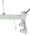
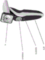
Accordingly, in one aspect, the invention features a treatment device that includes a base member and a head member having a distal portion and a proximal portion, the distal portion of the head member configured to contact an eyelid of a subject, and the proximal portion of the head member configured to be attached to the base member. The distal portion of the head member may be configured to deliver therapeutic doses of energy from a plurality of energy sources including a source of ultraviolet C (UVC) radiation, a source of Infrared (IR) radiation, and a source of ultrasound. The plurality of energy sources may be configured to deliver the therapeutic dose of energy to the eyelid of the subject at a predetermined power when the distal portion of the head member contacts the eyelid.
In some embodiments, the device further comprises a temperature sensor. The device may also include a heat source. The IR radiation source may be configured to provide heat. In some embodiments, the heat source comprises a resistance wire element. In some embodiments, the apparatus further comprises a microwave radiation source. In some embodiments, the device further comprises a strong pulsed light source. In some embodiments, the device further comprises a contact sensor that senses contact of the device with the eyelid.
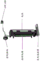
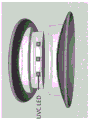
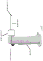
In another aspect, the invention features a treatment device that includes a base member and a head member having a distal portion and a proximal portion, the distal portion of the head member configured to deliver a therapeutic dose of UVC radiation from a UVC radiation source to an eye of a subject, and the proximal portion of the head member configured to be attached to the base member. The apparatus may further comprise a proximity determination element configured to detect a predetermined distance between the UVC radiation source and a treatment site of the eye. The apparatus may further comprise a signal generating element configured to generate a signal when the proximity determining element detects the predetermined distance, wherein the signal is configured to activate the UVC radiation source to deliver the therapeutic dose of UVC radiation to the eye of the subject at a predetermined power. The treatment device may further include a light guide having a proximal portion and a distal portion, the proximal portion of the light guide configured to be attached to the distal portion of the head piece, and the distal portion of the light guide configured to deliver the therapeutic dose of UVC radiation.
In another aspect, the invention features a sterilizing device including a base member and a head member having a distal portion and a proximal portion, the distal portion of the head member configured to deliver a sterilizing dose of UVC radiation from a UVC radiation source to a subject, and the proximal portion of the head member configured to be attached to the base member. The device may further include a light guide having a proximal portion and a distal portion, the proximal portion of the light guide configured to be attached to the distal portion of the head piece, and the distal portion of the light guide configured to deliver the sanitizing dose of UVC radiation. The device may further include a proximity determination element configured to detect a predetermined distance between the distal portion of the light guide and a treatment site of the subject. The apparatus may further comprise a signal generating element configured to generate a signal when the proximity determining element detects the predetermined distance, wherein the signal is configured to activate the UVC radiation source to deliver the disinfection dose at a predetermined power via the light guide.
In some embodiments, the head piece includes an aperture control element configured to adjust a UVC radiation dose. The orifice control element may include one or more removable cones. The orifice control element may be integrated within the head. The aperture of the UVC radiation source can be from about 1mm to about 50mm (e.g., from about 2mm to about 40mm, from about 4mm to about 40mm, such as about 25mm, such as about 4 mm).
In some embodiments of any of the above aspects, the UVC radiation source is configured to deliver a therapeutic dose of UVC to an anterior region, a posterior region, a vitreous cavity region, a retinal region, a choroidal region, a macular region, a lens region (e.g., an intraocular lens region), a ciliary muscle region, an optic nerve region, a lesion site, or a site affected by a foreign object of the eye. In some embodiments, the therapeutic dose of UVC is configured for delivery to the eye of the subject via a vitrectomy element. In some embodiments, the UVC radiation source is configured to deliver the therapeutic dose of UVC radiation to an interior region of the eye of the subject via a light guide configured to be inserted into the vitrectomy element and into the interior region of the eye of the subject.
In some embodiments of any of the above aspects, the UVC radiation source is configured to deliver the therapeutic dose of UVC to a wound. In some embodiments, the therapeutic dose of UVC improves wound healing (e.g., healing rate, degree of healing, and/or reduces scarring).
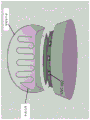
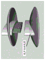
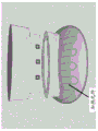
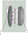
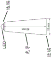
In some embodiments of any of the above aspects, the device comprises an eye stabilizing element comprising a proximal end configured to attach to the distal portion of the head piece and a distal end configured to contact and stabilize the eye. In some embodiments, the eye stabilizing element is shaped as a cone having a first diameter at the proximal end and a second diameter at the distal end.
In some embodiments, the first diameter is smaller than the second diameter, or the first diameter is larger than the second diameter. In some embodiments, the distal portion of the eye stabilizing element comprises a plurality of teeth configured to secure the eye of the subject. In some embodiments, the eye stabilizing element is composed of a material that is opaque to UVC light. In some embodiments, the eye stabilizing element is substantially hollow to provide a volume through which a therapeutic dose of UVC radiation from the head piece can propagate to a treatment site of the eye of the subject. In some embodiments, the eye stabilizing element is configured to prevent UVC radiation from irradiating healthy sites of the eye of the subject. In some embodiments, the eye stabilizing element is disposable. In some embodiments, the eye stabilizing element is provided for only a single use and includes a tag (e.g., radio Frequency Identification (RFID)) to prevent reuse of the eye stabilizing element. In some embodiments, the eye stabilizing element is non-sterilizable. In some embodiments, the eye stabilizing element is constructed of plastic. In some embodiments, the eye stabilizing element is transparent to visible light.
In another aspect, the invention features a treatment device that includes a base member and a head member having a distal portion and a proximal portion, the distal portion of the head member configured to deliver a therapeutic dose of ultraviolet a (UVA) radiation from a UVA radiation source to an eye of a subject, and the proximal portion of the head member configured to be attached to the base member. The apparatus may further comprise a proximity determination element configured to detect a predetermined distance between the UVA radiation source and a treatment site of the subject. The apparatus may further comprise a signal generating element configured to generate a signal when the proximity determining element detects the predetermined distance, wherein the signal is configured to activate the UVA radiation source to deliver the therapeutic dose of UVA radiation to the eye of the subject at a predetermined power.
In some embodiments, the apparatus further comprises an imaging module configured to display an image of the treatment site.
In some embodiments, the device is configured to be mounted on a slit lamp.
In some embodiments, the device further comprises a power source (e.g., a battery).
In some embodiments, the device further comprises a control mechanism, such as a control button. In some embodiments, the control mechanism is on the base member.
In some embodiments, the proximity determination element comprises two or more lasers. The proximity determination element may be configured to activate the signal generation element when the two or more lasers converge.
In some embodiments, the signal generating element is configured to provide an audible, visual or tactile signal.
In another aspect, the invention features an apparatus that includes a base member and a head member having a distal portion and a proximal portion, the distal portion of the head member configured to deliver a dose of UVC radiation from a UVC radiation source to a contact lens or lens, and the proximal portion of the head member configured to be attached to the base member. In some embodiments, the device further comprises a contact lens or lens case comprising an ultrasonic source, wherein the contact lens or lens case is attached to the distal portion of the head piece and is configured to deliver a dose of ultrasonic waves.
In another aspect, the invention features a system for delivering multiple energy sources to a tissue site. The system includes a base member having a proximal portion and a distal portion configured to mate with one of a plurality of interchangeable heads selected from two or more of: a first head comprising a UVC radiation source; a second head comprising an IR radiation source; a third head comprising an ultrasonic source; a fourth head comprising a UVA radiation source; a fifth head comprising a UVC radiation source, an IR radiation source, and an ultrasonic source; and a sixth head comprising a microwave radiation source and an intense pulsed light source. The first head may also include one or more of the following: a proximity determination element configured to detect a predetermined distance between the energy source and the application site; a signal generating element configured to generate a signal when the proximity determining element detects the predetermined distance; an orifice control module for adjusting an energy dose; a light guide; and an imaging module. In some embodiments, in which the system for delivering multiple energy sources to a tissue site includes a microwave radiation source and a strong pulsed light source, UVC radiation, IR radiation, ultrasound, microwave radiation, and strong pulsed light may be administered simultaneously. In some embodiments, the system for delivering multiple energy sources to a tissue site includes a microwave radiation source and an intense pulsed light source, the UVC radiation, IR radiation, ultrasound, microwave radiation, and intense pulsed light may be sequentially applied.
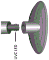
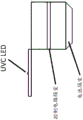
In some embodiments of any of the above aspects, the UVC radiation source comprises an LED. In some embodiments, the UVC radiation source comprises a plurality of LEDs. In some embodiments, the UVC radiation comprises the following peak wavelengths: about 100nm to about 290nm (e.g., about 200nm to about 290nm, e.g., about 220nm to about 290nm, e.g., about 240nm to about 280nm, e.g., about 250nm to about 280 or about 260nm to about 280nm, e.g., about 254nm, about 265nm, or about 275 nm). In some embodiments, the UVC radiation has a radiation intensity of about 20mW/cm 2 To about 1,000mW/cm 2 。
In some embodiments of any of the above aspects, the UVA radiation source comprises an LED. In some embodiments, the UVA radiation source comprises a plurality (e.g., 1, 2, 3, 4, 5, 6, 7, 8, 9, 10, or more) LEDs. The wavelength of the UVA radiation may be from about 315nm to about 400nm, for example, about 365nm or about 370nm. In some embodiments, the UVA radiation has a radiation intensity of about 0.5mW/cm 2 To about 100mW/cm 2 For example about 1mW/cm 2 To about 90mW/cm 2 About 2mW/cm 2 To about 80mW/cm 2 About 5mW/cm 2 To about 70mW/cm 2 About 10mW/cm 2 To about 60mW/cm 2 About 15mW/cm 2 To about 50mW/cm 2 About 20mW/cm 2 To about 45mW/cm 2 About 25mW/cm 2 To about 35mW/cm 2 . In some embodiments, the head further comprises an aperture control element configured to adjust the UVA radiation dose.
In some embodiments, the IR radiation source comprises an LED. The IR radiation source may comprise a plurality of LEDs. The IR radiation includes a peak wavelength of about 750nm to about 1,000,000 nm. The IR radiation may have a radiation intensity of about 20mW/cm 2 To about 1,000mW/cm 2 。
In some embodiments, the ultrasonic waves have a frequency of about 1MHz to about 10MHz.
In some embodiments of any of the above aspects, the head member and the base member are integral.
In some embodiments of any of the above aspects, the head member and the base member are separable.
In another aspect, the invention features a method for treating blepharitis or Meibomian Gland Disease (MGD): providing an apparatus as described herein; allowing the distal portion of the head member to contact the eyelid; and administering the therapeutic dose of energy from the plurality of energy sources to the eyelid.
In some embodiments, the UVC radiation, IR radiation, ultrasound, microwave radiation, and intense pulsed light may be administered simultaneously. Alternatively, in some embodiments, the UVC radiation, IR radiation, ultrasound, microwave radiation, and intense pulsed light may be applied sequentially.
In some embodiments, the method further comprises delivering heat.
In another aspect, the invention features a method for treating an eye infection (e.g., endophthalmitis), a cancer (e.g., eyelid cancer or eye cancer): providing a device as described herein and positioning the device in proximity to the treatment site. The method may comprise: detecting the predetermined distance by the proximity determination element; generating the signal by the signal generating element to activate the UVC radiation source; and administering the therapeutic dose of UVC radiation to the eyelid or the treatment site of the eye.
In another aspect, the invention features a method of treating cancer: providing a device as described herein and positioning the device in proximity to the treatment site; detecting the predetermined distance by the proximity determination element; generating the signal by the signal generating element to activate the UVC radiation source; and administering the therapeutic dose of UVC radiation to the treatment site.
In some embodiments, the cancer is eyelid cancer or eye cancer. In some embodiments, the cancer is intraocular melanoma, retinoblastoma, uveal melanoma, conjunctival melanoma, orbital cancer, or an accessory cancer.
In some embodiments of any of the aspects described herein, the devices and methods can be used to treat cancer, neoplasia, and/or dysplasia, including, for example, cancer cells or pre-cancerous cells.
In another aspect, the invention features a method for disinfecting tissue of a subject: a device as described herein is provided and a light guide is positioned proximate to the treatment site. The method may comprise: detecting the predetermined distance by the proximity determination element; generating the signal by the signal generating element to activate the UVC radiation source; and administering the therapeutic dose of UVC radiation via the light directed to the treatment site in the tissue of the subject.
In some embodiments, the tissue is selected from the group consisting of eye, nasal cavity, oral cavity, skin tissue, and inner cavity. In some embodiments, the subject has or is suspected of having a bacterial infection (e.g., chlamydia trachomatis, streptococcus pneumoniae, haemophilus influenzae), a fungal infection, an amoeba infection, a parasitic infection (e.g., toxoplasmosis, toxoplasma, infectious retinitis), or a viral infection (e.g., a respiratory tract infection, such as respiratory syncytial virus, influenza virus, or SARS-CoV 2). In some embodiments, the subject has acne vulgaris and/or rosacea. In some embodiments, the subject has an ulcer, e.g., caused by helicobacter pylori. In some embodiments, the subject has or is suspected of having a herpes viral infection. In some embodiments, the subject has or is suspected of having a human immunodeficiency virus infection. In some embodiments, the herpes virus infection is located in epithelial tissue, such as genital tissue, lips, or other parts of the skin. In some embodiments, the subject has or is suspected of having a human papillomavirus infection. In some embodiments, the human papillomavirus infects tissue located in the cervix.
In another aspect, the invention features a method for treating corneal ectasia (e.g., keratoconus) in a subject: providing a device as described herein and positioning the device in proximity to the treatment site, wherein the subject has administered a dose of a photoactivator. Suitable photoactivators include, but are not limited to, riboflavin, rose bengal, porphyrin-based photosensitizers, psoralens, quinones, anthracyclines, anthraquinones, xanthenes, luciferins, rhodamine, phthalides, cyan pigments, chalcone (chalcone) dyes, triarylmethane dyes, phenothiazines, phenoxazines, acridines, hypericin, nicotinamide Adenine Dinucleotide Phosphate (NADPH), 5-aminolevulinic acid, ciprofloxacin, and quinine. The photoactivator may be administered at the treatment site. In some embodiments, the method comprises: detecting the predetermined distance by the proximity determination element; generating the signal by the signal generating element to activate the UVA radiation source; and administering the therapeutic dose of UVA radiation to the treatment site in the eye.
In another aspect, the invention features a method for sterilizing a contact lens or lens, the method including: providing an apparatus as described herein; placing the contact lens or lenses in the box; and applying the UVC radiation source and the ultrasonic source to the contact lens or lens. In some embodiments, UVC radiation and ultrasound are administered simultaneously. In some embodiments, the UVC radiation and ultrasound are administered sequentially.
In another aspect, the invention features a contact lens having a proximal end and a distal end, the contact lens configured to direct a therapeutic dose of UVC radiation from a UVC radiation source toward an eye of a subject. In some embodiments, the contact lens comprises the UVC radiation source. In some embodiments, the UVC radiation source comprises an LED. In some embodiments, the UVC radiation source comprises a plurality (e.g., 1, 2, 3, 4, 5, 6, 7, 8, 9, 10, or more) LEDs. In some embodiments, the UVC radiation source comprises a plurality of Surface Mount Device (SMD) LEDs. In some embodiments, the plurality of LEDs are configured to be attached to the contact lens, configured to be incorporated within the lens, or configured to be focused by the lens. In some embodiments, the proximal end of the contact lens is configured to contact the eye of the subject, and wherein the distal end is configured to mate with an external UVC radiation source. In some embodiments, the external UVC radiation source delivers the therapeutic dose of UVC to the distal end of the contact lens through a light guide. In some embodiments, the UVC radiation comprises the following peak wavelengths: about 100nm to about 290nm (e.g., about 200nm to about 290nm, e.g., about 220nm to about 290nm, e.g., about 240nm to about 280nm, e.g., about 250nm to about 280 or about 260nm to about 280nm, e.g., about 254nm, about 265nm, or about 275 nm). In some embodiments, the UVC radiation has a radiation intensity of about 20mW/cm 2 To about 1,000mW/cm 2 . In some embodiments, the contact lens includes a power source that is a battery, an energy transfer antenna, a solar cell, an inertial force collector, or an electrical plug.
In another aspect, the invention features a method for treating an eye infection, the method including: providing a contact lens having a UVC radiation source as described herein; positioning the contact lens over a site of the eye infection; and administering a therapeutic dose of UVC radiation to the eyelid or the treatment site of the eye.
In another aspect, the invention features a method of treating a wound in a subject, the method including providing a treatment device as described herein and administering a therapeutic dose of UVC radiation to the wound.
Definition of the definition
In order to facilitate an understanding of the present invention, a number of terms are defined below. The terms defined herein have meanings as commonly understood by one of ordinary skill in the art to which the invention pertains. Terms such as "a/an" and "the" are not intended to refer to only a single entity, but rather include general categories that may be illustrated using a particular example. The terminology herein is used to describe specific embodiments of the invention, but their use does not limit the invention unless outlined in the claims.
As used herein, the term "about" refers to a value within 10% of the value.
As used herein, the term "cancer" refers to a disease caused by uncontrolled cell division and cell metastasis or the ability to establish new growth points at additional sites. The term cancer includes, for example, leukemia, seminoma, melanoma, teratoma, lymphoma, neuroblastoma, glioma, rectal cancer, endometrial cancer, renal cancer, adrenal cancer, thyroid cancer, blood cancer, skin cancer, brain cancer, cervical cancer, intestinal cancer, liver cancer, colon cancer, gastric cancer, intestinal cancer, head and neck cancer, gastrointestinal cancer, lymph node cancer, esophageal cancer, colorectal cancer, pancreatic cancer, ear-nose-throat cancer (ENT), breast cancer, prostate cancer, uterine cancer, ovarian cancer, and lung cancer, as well as metastases thereof. Examples thereof are lung cancer, breast cancer, prostate cancer, colon cancer, renal cell carcinoma, cervical cancer or metastasis of cancers or tumors of the type described above. The term cancer according to the invention also encompasses cancer metastasis and/or cancer of surrounding tissue, such as orbital cancer or an appendage cancer. As used herein, cancer also includes neoplasia and dysplasia, including, for example, cancer cells or tissues and pre-cancer cells or tissues.
As used herein, the term "disinfecting dose of energy" refers to electromagnetic energy (e.g., UV), mechanical energy (e.g., ultrasonic energy), thermal energy, or any combination thereof, that is suitable for achieving a desired disinfecting effect when used in an appropriate therapeutic regimen, such as reducing the amount of microbial load (e.g., bacterial load, fungal, protozoa, parasitic, or viral load) on a target site.
The term "energy guide" as used herein refers to any element capable of transmitting any kind of energy (e.g., electromagnetic energy, mechanical energy, thermal energy 1 from one end to the other, in one embodiment, the light guide may be an optical fiber.
As used herein, the term "energy source" refers to a source of electromagnetic radiation, a source of mechanical energy (e.g., acoustic or ultrasonic), a source of thermal energy, or any combination thereof. The energy source may include multiple sources and energy from the energy source may be applied directly to the target site or through an energy guide.
As used herein, the term "imaging module" describes an imaging element and processing circuitry for generating a video signal.
As used herein, the term "integral" refers to, relating to or being part of the entire device; i.e. is necessary for the integrity of the whole; is composed of or consists of a plurality of parts which together form a whole.
As used herein, the term "intense pulsed light" or "IPL" refers to non-laser-like light that has a range of wavelengths and is emitted periodically in the form of intense pulses. For example, IPL is light with a wavelength range of about 300 to 1,200nm (varying according to the IPL device) and periodically emitted in the form of intense pulses. The IPL irradiation device uses a flash lamp emitting light with a wavelength of about 300-1,200nm, and controls the wavelength of the light emitted by the filter. IPL energy is delivered as a series of single, double, or triple pulse sequences with pulse durations of 2-25ms and inter-pulse delays of 10-500 ms. IPL radiant energyThe density can range from 5J/cm 2 To 60J/cm 2 。
As used herein, the term "light guide" refers to an article that receives light at an input end and propagates the light to an output end or extraction mechanism without significant loss. In general, light guides function according to the principle of total internal reflection, whereby light propagating through the light guide is reflected at the surface of the light guide based on the difference in refractive index of the light guide material and the material (e.g., air, cladding, etc.) that tightly surrounds the light guide.
As used herein, the term "proximity determination element" refers to any device capable of measuring the distance from the device described herein to the surface of the treatment site or application site.
As used herein, the term "respiratory tract infection" includes the invasion and/or proliferation and/or colonization of pathogenic microorganisms (e.g., bacteria and viruses) in one or more components of the respiratory tract (e.g., such as the lungs, epiglottis, trachea, bronchi, bronchioles, or alveoli).
As used herein, the term "separable" means that a device component, module, element, or any variation thereof, can be readily connected or disconnected by engaging or disengaging the connection at a working interface.
As used herein, the term "signal generating element" refers to a component of a device as described herein that can provide a detectable signal (e.g., an audible signal, visual cue, tactile feedback) in response to a measured distance value (e.g., as measured by a proximity determining element of the device described herein).
As used herein, the terms "sterilization" and "disinfection" or variants thereof refer to reducing the load of microorganisms (e.g., pathogenic and/or non-pathogenic) on or in living tissue or body parts of a subject, or on or in inanimate objects. As used herein, these terms are used interchangeably.
As used herein, the term "subject" refers to a mammal, including a human in need of treatment or susceptible to a disorder or sequelae. The subject may include dogs, cats, pigs, cattle, sheep, goats, horses, rats and mice, and humans. The term "subject" does not exclude individuals who are normal in all respects.
As used herein, the term "sufficient distance and time" refers to the period of time and distance from a target site (e.g., body part, surface, or object) to which light or other energy form (e.g., mechanical or thermal energy form) generated by the device is exposed in order to deliver a therapeutic dose of energy. In one embodiment, the period of time is from about 0.01 seconds to about 30 minutes. In one embodiment, a shutter is utilized to open, close and regulate the passage of energy from the energy source to the target site. The exposure may be directly from the end of the energy source or continued to the end of the energy guide via an energy guide (e.g., a light guide), particularly for application of a therapeutic dose of energy into the lumen of the body, either directly or through the skin of the subject.
As used herein, the term "therapeutic dose of energy" refers to an amount of electromagnetic energy, mechanical energy (e.g., ultrasonic energy), thermal energy, or a combination thereof that is suitable to achieve a desired therapeutic effect, such as lessening the severity of a disease symptom or condition, when used in an appropriate therapeutic regimen. The dose may be considered to be a therapeutic dose for treating cancer or metastasis if the amount of energy applied is sufficient to bring about the following effects: the growth of the tumor or metastasis is slowed or stopped, or the tumor or metastasis is found to decrease in size, and/or the patient's life is prolonged. The dose may be considered to be a therapeutic dose for treating a bacterial infection, a fungal infection, a protozoal infection or a viral infection if the amount of energy applied is sufficient to bring about the following effects: the infection slows down or stops, and/or the patient's life becomes longer. Appropriate therapeutic doses will generally balance therapeutic effects with tolerance to toxicity, for example, when side effects and toxicity are tolerated, provided that treatment is beneficial.
As used herein, the term "treatment" (also referred to as "treatment") or "treatment") in its broadest sense refers to any administration of a therapeutic agent (e.g., ultraviolet light) that partially or completely alleviates, ameliorates, alleviates, inhibits one or more symptoms, features, or etiologies of a particular disease, disorder, or condition, delays its onset, reduces its serious course, or reduces its incidence. In some embodiments, such treatments may be administered to subjects that do not exhibit signs of the associated disease, disorder, or condition or subjects that exhibit only early signs of the disease, disorder, or condition. Alternatively or additionally, in some embodiments, the treatment may be administered to a subject exhibiting one or more established signs of the associated disease, disorder, or condition. In some embodiments, the treatment may be directed to a subject that has been diagnosed as having a related disease, disorder, or condition. In some embodiments, the treatment may be directed to a subject known to have one or more susceptibility factors that are statistically correlated with an increased risk of progression of the associated disease, disorder, or condition.
Drawings
Fig. 1 is a schematic diagram showing a control side of a therapeutic apparatus. Showing the base member, control buttons and interchangeable head member (indicated by asterisks).
Fig. 2 is a schematic diagram showing a treatment side of the treatment device. A base member, UVC LED source and interchangeable head member (indicated by asterisks) are shown.
Fig. 3 is a schematic diagram showing a side view of a treatment device and a charge docking station.
Fig. 4 is a schematic diagram showing the internal components of the treatment delivery device. Control buttons, control circuitry, charging connectors, batteries, and UVC LED components are shown.
Fig. 5 is a schematic diagram illustrating an energy delivery head assembly. A plurality of UVC LEDs are depicted and may be connected to a module comprising a heating element and an eyelid speculum.
Fig. 6 is a schematic diagram showing an energy delivery head assembly configured with an ultrasonic transducer and a heating element.
Fig. 7A-7D are schematic diagrams illustrating multiple views of an energy delivery head module configured to deliver UVC light, ultrasound, and heat. Fig. 7A shows an ultrasonic transducer, fig. 7B shows a heating element, and fig. 7C and 7D show UVC LEDs.
Fig. 8 is a schematic diagram illustrating an energy delivery head module configured to deliver UVC light, ultrasound, and heat.
Fig. 9 is a schematic diagram showing the control side of the treatment apparatus. Showing the head part, control buttons, power button and base part.
Fig. 10 is a schematic diagram showing a side view of a treatment apparatus including a base member and a head member.
Fig. 11 is a schematic view of the treatment side of the treatment device. An imaging module (HD camera), UVC LED source, proximity measurement element and base member are shown.
Fig. 12 is a schematic view of the control side of the treatment apparatus. A video screen, a head module, control buttons, power buttons, and base members are shown.
Fig. 13 is a schematic diagram showing a control side of the therapeutic apparatus. A video screen, a head module, control buttons, power buttons, and base members are shown.
Fig. 14 is a schematic view of the treatment side of the treatment apparatus. An imaging module (HD camera), UVC LED source, proximity measurement element and base member are shown.
Fig. 15 is a schematic diagram showing a control side of the therapeutic apparatus. A signal generating element (video screen), control buttons, power buttons and base unit are shown.
Fig. 16 is a set of schematic diagrams of the treatment side of the treatment apparatus. A proximity measurement element and UVA LED array are shown.
Fig. 17 is a schematic view of the treatment side of the treatment apparatus. A proximity measurement element and UVA LED array are shown.
Fig. 18 is a schematic view of a UVC sterilization apparatus. A plurality of UVC LED sources, a base member configured to deliver ultrasound waves, and a contact lens aperture are shown.
Fig. 19 is a schematic view of a UVC sterilization apparatus. A plurality of UVC LED sources, a base member configured to deliver ultrasound waves, and a contact lens aperture are shown.
Fig. 20 is a schematic diagram of a top view of a UVC sterilization apparatus. A plurality of UVC LED sources, a base member configured to deliver ultrasound waves, and a contact lens aperture are shown.
Fig. 21 is a schematic diagram of a side view of a UVC sterilization apparatus. A control circuit compartment and a battery compartment configured to deliver ultrasound and UVC are shown.
Fig. 22 is a schematic view of the internal components of the base of the UVC sterilization device. A control circuit compartment configured to deliver ultrasound and UVC, a battery compartment, and an ultrasound transducer are shown.
Fig. 23 is a schematic view of an embodiment of a vitrectomy element shown connected to the distal end of a head piece of a UVC sterilization device. A vitrectomy probe and vitrectomy probe opening are shown. In this embodiment, UVC radiation enters at one end of the vitrectomy element and exits at a vitrectomy probe opening configured to be inserted into an interior region of the eye.
Fig. 24A is a schematic diagram of a side view of an embodiment of a vitrectomy element shown with a 6mm diameter base and a 12mm length vitrectomy probe, and a vitrectomy probe opening shown with a 1mm diameter.
Fig. 24B is a schematic diagram of a perspective view of an embodiment of a vitrectomy element shown with a 1mm diameter vitrectomy probe opening.
Fig. 25 is a schematic diagram showing an embodiment of a light guide delivering UVC light into the vitreous of an eye. A needle may be used in combination to extract a portion of the vitreous.
Fig. 26A and 26B are schematic views of an embodiment of an eye stabilization element having a length of 10mm from a proximal end to a distal end. The distal end is shown as a smooth edge. The eye stabilizing element is shown in the shape of a cone having a diameter at the proximal end that is larger than the diameter at the distal end. The distal end contacts the subject's eye to stabilize the eye and minimize eye movement. The proximal end is configured to attach to a distal end of a head piece of the device. Fig. 27A is a side view, and fig. 27B is a perspective view. The distal end is shown as having a diameter of 6mm and the proximal end is shown as having a diameter of 10mm.
Fig. 27A is a schematic view of an embodiment of an eye stabilization element. The distal end is shown with a smooth edge. The eye stabilizing element is shown in the shape of a cone having a diameter at the proximal end that is larger than the diameter at the distal end. The distal end contacts the subject's eye to stabilize the eye and minimize eye movement. The proximal end is configured to attach to a distal end of a head piece of the device.
Fig. 27B is a schematic view of an embodiment of an eye stabilization element. The distal end is shown with castellated edges and teeth. The eye stabilizing element is shown in the shape of a cone having a diameter at the proximal end that is larger than the diameter at the distal end. The distal end contacts the subject's eye to stabilize the eye and minimize eye movement. The proximal end is configured to attach to a distal end of a head piece of the device.
Fig. 28A is a schematic diagram of an embodiment of a lightguide for delivering a therapeutic dose of UVC to the mouth of a subject (e.g., to treat gingivitis). This exemplary embodiment is shown as having a length of 40mm from the proximal end to the distal end and a diameter of 15mm at the proximal end. The light guide is configured to be attached at a proximal end to a head piece of the device. The light guide is configured with UVC LEDs at the distal end.
Fig. 28B is a schematic diagram of a top view of an embodiment of a lightguide for delivering a therapeutic dose of UVC to a subject's mouth (e.g., to treat gingivitis). UVC LEDs are shown.
Fig. 28C is a schematic diagram of a side view of an embodiment of a lightguide for delivering a therapeutic dose of UVC to a subject's mouth (e.g., to treat gingivitis). The proximal and distal ends and the UVC LEDs at the distal end are shown.
Fig. 28D is a side view of an embodiment of a lightguide for delivering a therapeutic dose of UVC to the mouth of a subject (e.g., to treat gingivitis). The light guide is shown attached to the head part as well as the base part and the UVC LEDs.
Detailed Description
The invention features devices, systems, and methods of use thereof for delivering therapeutic or sterilizing Ultraviolet (UV) radiation. The devices and systems described herein may be used for a variety of purposes, including the treatment of eye disorders, such as blepharitis, meibomian Gland Disease (MGD), eye cancer, eye infection, and keratoconus. The devices described herein may be used to provide sterilizing or therapeutic radiation to various tissues of a subject, such as the eye, nasal cavity, oral cavity, skin tissue, or lumen. The devices may also be used to treat cancer (e.g., eye cancer or eyelid cancer), neoplasia, and/or dysplasia. Generally, the device includes a base member and a head member attached thereto, the head member configured to deliver therapeutic or sterilizing UV radiation (e.g., UVA or UVC) to a treatment site within a subject or to a device. The device may also be designed in a multi-functional manner such that a single device may be used with multiple interchangeable heads, each of which may be used according to a desired purpose or function. The components of the apparatus and system are described in more detail below.
Base component
The base member of the device as described herein includes a distal portion and a proximal portion configured as a connector member. The base member may be of any suitable size and shape such that it is suitably configured to receive the head member thereon. The base member may have an ergonomic design to allow easy control of the hand-held device. For example, the base member may include a handle such that the device may be easily manipulated by a user (e.g., a healthcare provider). The base member may be configured to be mounted on another device or instrument, such as a microscope, a slit lamp, a power source, or an energy (e.g., UV (e.g., UVA or UVC), IR, heat, and ultrasound) source. The base member may include a housing, for example, on a distal portion thereof for attaching a joint member or other accessory member. The base member may include a housing for mounting the base member to another instrument (e.g., a slit lamp). The base member may be designed to be removably attached to (e.g., separable from) the head member, and the base member and the head member form a system. Alternatively, the base part may be designed in one piece with the head part.
Head unit
The head pieces of the devices as described herein include a distal portion configured to deliver a therapeutic energy source (e.g., UV, IR, heat, microwaves, intense pulsed light, and/or ultrasound) to a treatment or sterilization site and a proximal portion. The proximal portion of the head member is configured to be attached or mounted to the base member. The head member may have any suitable geometry to match its function, for example to deliver therapeutic energy to an appropriate site (e.g., an eye, eyelid, nasal cavity, oral cavity, tooth cavity, periodontal tissue, skin tissue or cavity (e.g., gastrointestinal cavity, oropharyngeal cavity, reproductive cavity, or urinary cavity). For example, the device configured to deliver therapeutic energy to the eyelid may include a head member sized and shaped (e.g., curvature) to conform to the eyelid or pair of eyelids of a subject.
The head piece may house a therapeutic energy source, e.g., a therapeutic energy (e.g., UV) source integrated within or on the head. Alternatively, the head piece may act as an emitter that directs a therapeutic energy source to the application site via the source. In some embodiments, the device further comprises a light guide for delivering UV radiation. The light guide may be attached to a head piece that transfers therapeutic energy from the source to the application site via the light guide.
UV radiation
The devices described herein include a UV radiation source. The UV radiation may be, for example, UVC radiation, UVA radiation, or a combination thereof. The wavelength of UVC radiation may be from about 100nm to about 280nm (e.g., from about 200nm to about 280nm, such as from about 220nm to about 280nm, such as from about 240nm to about 270nm, such as from about 250nm to about 270 or from about 260nm to about 270nm, such as from about 254nm, 255nm or about 265 nm). The UVA radiation may have a wavelength of about 315nm to about 400nm. The UV radiation source may be configured to emit radiation at a plurality of wavelengths. The source may be tunable so as to emit radiation at a selected wavelength. The UV radiation source may comprise at least one Light Emitting Diode (LED) or a plurality of LEDs emitting UV radiation. For example, the source may comprise 1, 2, 3, 4, 5, 6, 7, 8, 9, 10 or more LEDs emitting UV radiation. In one embodiment, the UV radiation source comprises eight LEDs.
In some embodiments, the power output of the UV radiation source is about 0.005mW to about 50mW (e.g., about 0.005mW to about 5mW, e.g., about 0.01mW to about 1 mW). For example, the power output of the UV radiation source may be about 0.005mW to about 0.01mW, e.g., about 0.006mW, 0.007mW, 0.008mW, 0.009mW, or 0.01mW, e.g., about 0.01mW to about 0.1mW, e.g., about 0.02mW, 0.03mW, 0.04mW, 0.05mW, 0.06mW, 0.07mW, 0.08mW, 0.09mW, or 0.1mW, e.g., about 0.1mW to about 1mW, e.g., about 0.2mW, 0.3mW, 0.4mW, 0.5mW, 0.6mW, 0.7mW, 0.8mW, 0.9mW or 1mW, e.g., about 2mW, 3mW, 4mW, 5mW, 6mW, 7mW, 8mW, 10mW, about 50mW, or about 40mW, about 50mW, or about 0.0 mW. The power of the source may be adjustable to transmit a desired power output.
The UV radiation source may be configured to irradiate the entire surface of the eye. The UV radiation source may be configured to irradiate a tissue region having a largest dimension of less than about 10cm, such as less than about 9cm, 8cm, 7cm, 6cm, 5cm, 4cm, 3cm, 2cm, 1cm, 0.9cm, 0.8cm, 0.7cm, 0.6cm, 0.5cm, 0.4cm, 0.3cm, 0.2cm, or 0.1cm. The radiation source may be configured to irradiate a substantially circular tissue region, an elongated tissue region, or an annular body tissue region. In some embodiments, the radiation source is configured to be adjustable to adjust the size and/or shape of the irradiated region. The device may be configured to scan UV radiation across a body tissue region. This may be achieved, for example, by moving the base member or the handle above, or by rotating or moving members, for example, in the head member.
In some embodiments, the UV radiation source produces the following radiation intensities: about 0.01mW/cm 2 To about 500mW/cm 2 For example about 0.01mW/cm 2 To about 50mW/cm 2 For example about 0.01mW/cm 2 To about 5mW/cm 2 . For example, a UV radiation source may produce the following radiation intensities: about 0.01mW/cm 2 To about 0.1mW/cm 2 For example about 0.02mW/cm 2 、0.03mW/cm 2 、0.04mW/cm 2 、0.05mW/cm 2 、0.06mW/cm 2 、0.07mW/cm 2 、0.08mW/cm 2 、0.09mW/cm 2 、0.1mW/cm 2 For example about 0.1mW/cm 2 To about 1mW/cm 2 For example about 0.2mW/cm 2 、0.3mW/cm 2 、0.4mW/cm 2 、0.5mW/cm 2 、0.6mW/cm 2 、0.7mW/cm 2 、0.8mW/cm 2 、0.9mW/cm 2 Or 1mW/cm 2 For example about 1mW/cm 2 To about 10mW/cm 2 For example about 2mW/cm 2 、3mW/cm 2 、4mW/cm 2 、5mW/cm 2 、6mW/cm 2 、7mW/cm 2 、8mW/cm 2 、9mW/cm 2 、10mW/cm 2 For example about 10mW/cm 2 To about 100mW/cm 2 For example about 20mW/cm 2 、30mW/cm 2 、40mW/cm 2 、50mW/cm 2 、60mW/cm 2 、70mW/cm 2 、80mW/cm 2 、90mW/cm 2 Or 100mW/cm 2 For example about 100mW/cm 2 To about 500mW/cm 2 For example about 150mW/cm 2 、200mW/cm 2 、250mW/cm 2 、300mW/cm 2 、350mW/cm 2 、400mW/cm 2 、450mW/cm 2 Or 500mW/cm 2 。
The UV radiation source may be applied over a period of time. The dose may be administered as a continuous dose or as a pulsed dose. The dose may be administered, for example, from about 0.01 seconds to about 600 seconds, such as from about 0.01 seconds to about 0.1 seconds, such as from about 0.02 seconds, 0.03 seconds, 0.04 seconds, 0.05 seconds, 0.06 seconds, 0.07 seconds, 0.08 seconds, 0.09 seconds, or 0.1 seconds, such as from about 0.1 seconds to about 1 second, such as from about 0.2 seconds, 0.3 seconds, 0.4 seconds, 0.5 seconds, 0.6 seconds, 0.7 seconds, 0.8 seconds, 0.9 seconds, or 1 second, such as from about 1 second to about 10 seconds, such as from about 2 seconds, 3 seconds, 4 seconds, 5 seconds, 6 seconds, 7 seconds, 8 seconds, 9 seconds, or 10 seconds, such as from about 10 seconds to about 100 seconds, such as from about 20 seconds, 30 seconds, 40 seconds, 50 seconds, 60 seconds, 70 seconds, 80 seconds, 90 seconds, or 100 seconds, such as from about 100 seconds to about 600 seconds, such as from about 110 seconds, 120, 150, 180, 240, 300, 330, 360, 500, 510, 570, or 1 second, 500, or 10 seconds. The pulse dose of radiation may include the following on-time to off-time ratios: such as from about 0.01 to about 100, such as from about 0.01 to about 0.1, such as from about 0.02, 0.03, 0.04, 0.05, 0.06, 0.07, 0.08, 0.09, or 0.1, such as from about 0.1 to about 1, such as from about 0.2, 0.3, 0.4, 0.5, 0.6, 0.7, 0.8, 0.9, or 1, such as from about 1 to about 10, such as from about 2, 3, 4, 5, 6, 7, 8, 9, or 10, such as from about 10 to about 100, such as from about 20, 30, 40, 50, 60, 70, 80, 90, or 100. The pulsed dose of radiation may comprise a pulse shape or waveform selected from the group consisting of: square, triangular, sinusoidal, saw tooth, and any superposition or combination thereof.
The UV radiation source may be applied at the following doses: about 0.01mJ/cm 2 To about 500mJ/cm 2 For example about 0.01mJ/cm 2 To about 250mJ/cm 2 For example about 0.01mJ/cm 2 To about 15mJ/cm 2 For example about 1mJ/cm 2 To about 15mJ/cm 2 . For example, the radiation source may be administered at the following doses: about 0.01mJ/cm 2 To about 0.1mJ/cm 2 For example about 0.02mJ/cm 2 、0.03mJ/cm 2 、0.04mJ/cm 2 、0.05mJ/cm 2 、0.06mJ/cm 2 、0.07mJ/cm 2 、0.08mJ/cm 2 、0.09mJ/cm 2 Or 0.1mJ/cm 2 For example about 0.1mJ/cm 2 To about 1mJ/cm 2 For example about 0.2mJ/cm 2 、0.3mJ/cm 2 、0.4mJ/cm 2 、0.5mJ/cm 2 、0.6mJ/cm 2 、0.7mJ/cm 2 、0.8mJ/cm 2 、0.9mJ/cm 2 Or 1mJ/cm 2 For example about 1mJ/cm 2 To about 10mJ/cm 2 For example about 2mJ/cm 2 、3mJ/cm 2 、4mJ/cm 2 、5mJ/cm 2 、6mJ/cm 2 、7mJ/cm 2 、8mJ/cm 2 、9mJ/cm 2 Or 10mJ/cm 2 For example about 10mJ/cm 2 To about 100mJ/cm 2 For example about 20mJ/cm 2 、30mJ/cm 2 、40mJ/cm 2 、50mJ/cm 2 、60mJ/cm 2 、70mJ/cm 2 、80mJ/cm 2 、90mJ/cm 2 Or 100mJ/cm 2 For example about 100mJ/cm 2 To about 250mJ/cm 2 For example about 125mJ/cm 2 、150mJ/cm 2 、175mJ/cm 2 、200mJ/cm 2 、225mJ/cm 2 Or 250mJ/cm 2 . In some embodiments, the UV radiation source includes an adaptive optics configured to adjust a focus of the UV radiation.
IR radiation
The devices described herein may include an IR radiation source. The wavelength of the IR radiation may be from about 750nm to about 1,000,000nm (e.g., from about 800nm to about 900,000nm, from about 810nm to about 500,000nm, from about 820nm to about 250,000nm, from about 830nm to about 100,000nm, from about 850nm to about 50,000nm, from about 860nm to about 25,000nm, from about 870nm to about 10,000nm, from about 880nm to about 9,000nm, from about 890nm to about 8,000nm, from about 900nm to about 7,000nm, from about 910nm to about 6,000nm, from about 920nm to about 5,000nm, from about 930nm to about 4,000nm, from about 940nm to about 3,000nm, from about 950nm to about 2,500nm, from about 960nm to about 2,400nm, from about 970nm to about 2,300nm, from about 980nm to about 200nm, from about 990 to about 2,100nm, or from about 1,000nm to about 2,000 nm). The IR radiation source may be configured to emit radiation at a plurality of wavelengths. The source may be tunable so as to emit radiation at a selected wavelength. The IR radiation source may comprise at least one Light Emitting Diode (LED) or a plurality of LEDs emitting IR radiation. For example, the source may include 1, 2,3, 4, 5, 6, 7, 8, 9, 10, or more LEDs that emit IR radiation.
In some embodiments, the power output of the IR radiation source is about 0.005mW to about 50mW (e.g., about 0.005mW to about 5mW, e.g., about 0.01mW to about 1 mW). For example, the power output of the IR radiation source may be about 0.005mW to about 0.01mW, e.g., about 0.006mW, 0.007mW, 0.008mW, 0.009mW, or 0.01mW, e.g., about 0.01mW to about 0.1mW, e.g., about 0.02mW, 0.03mW, 0.04mW, 0.05mW, 0.06mW, 0.07mW, 0.08mW, 0.09mW, or 0.1mW, e.g., about 0.1mW to about 1mW, e.g., about 0.2mW, 0.3mW, 0.4mW, 0.5mW, 0.6mW, 0.7mW, 0.8mW, 0.9mW or 1mW, e.g., about 2mW, 3mW, 4mW, 5mW, 6mW, 7mW, 8mW, 10mW, about 50mW, or about 40mW, about 50mW, or about 0.0 mW. The power of the source may be adjustable to transmit a desired power output.
The IR radiation source may be configured to irradiate a tissue region having a maximum dimension of less than about 10cm, such as less than about 90mm, 80mm, 70mm, 60mm, 50mm, 40mm, 30mm, 20mm, or 10mm, such as less than about 9mm, 8mm, 7mm, 6mm, 5mm, 4mm, 3mm, 2mm, or 1mm. The radiation source may be configured to irradiate a substantially circular tissue region, an elongated tissue region, or an annular body tissue region. In some embodiments, the radiation source is configured to be adjustable to adjust the size and/or shape of the irradiated region. The device may be configured to scan IR radiation across a body tissue region. This may be achieved, for example, by moving the base member or the handle above, or by rotating or moving members, for example, in the head member.
In some embodiments, the IR radiation source produces the following radiation intensities: about 0.01mW/cm 2 To about 500mW/cm 2 For example about 0.01mW/cm 2 To about 50mW/cm 2 For example about 0.01mW/cm 2 To about 5mW/cm 2 . For example, an IR radiation source may produce the following radiation intensities: about 0.01mW/cm 2 To about 0.1mW/cm 2 For example about 0.02mW/cm 2 、0.03mW/cm 2 、0.04mW/cm 2 、0.05mW/cm 2 、0.06mW/cm 2 、0.07mW/cm 2 、0.08mW/cm 2 、0.09mW/cm 2 、0.1mW/cm 2 For example about 0.1mW/cm 2 To about 1mW/cm 2 For example about 0.2mW/cm 2 、0.3mW/cm 2 、0.4mW/cm 2 、0.5mW/cm 2 、0.6mW/cm 2 、0.7mW/cm 2 、0.8mW/cm 2 、0.9mW/cm 2 Or 1mW/cm 2 For example about 1mW/cm 2 To about 10mW/cm 2 For example about 2mW/cm 2 、3mW/cm 2 、4mW/cm 2 、5mW/cm 2 、6mW/cm 2 、7mW/cm 2 、8mW/cm 2 、9mW/cm 2 、10mW/cm 2 For example about 10mW/cm 2 To about 100mW/cm 2 For example about 20mW/cm 2 、30mW/cm 2 、40mW/cm 2 、50mW/cm 2 、60mW/cm 2 、70mW/cm 2 、80mW/cm 2 、90mW/cm 2 Or 100mW/cm 2 For example about 100mW/cm 2 To about 500mW/cm 2 For example about 150mW/cm 2 、200mW/cm 2 、250mW/cm 2 、300mW/cm 2 、350mW/cm 2 、400mW/cm 2 、450mW/cm 2 Or 500mW/cm 2 。
The IR radiation source may be applied over a period of time. The dose may be administered as a continuous dose or as a pulsed dose. The dose may be administered, for example, from about 0.01 seconds to about 600 seconds, such as from about 0.01 seconds to about 0.1 seconds, such as from about 0.02 seconds, 0.03 seconds, 0.04 seconds, 0.05 seconds, 0.06 seconds, 0.07 seconds, 0.08 seconds, 0.09 seconds, or 0.1 seconds, such as from about 0.1 seconds to about 1 second, such as from about 0.2 seconds, 0.3 seconds, 0.4 seconds, 0.5 seconds, 0.6 seconds, 0.7 seconds, 0.8 seconds, 0.9 seconds, or 1 second, such as from about 1 second to about 10 seconds, such as from about 2 seconds, 3 seconds, 4 seconds, 5 seconds, 6 seconds, 7 seconds, 8 seconds, 9 seconds, or 10 seconds, such as from about 10 seconds to about 100 seconds, such as from about 20 seconds, 30 seconds, 40 seconds, 50 seconds, 60 seconds, 70 seconds, 80 seconds, 90 seconds, or 100 seconds, such as from about 100 seconds to about 600 seconds, such as from about 110 seconds, 120, 150, 180, 240, 300, 330, 360, 500, 510, 570, or 1 second, 500, or 10 seconds. The pulse dose of radiation may include the following on-time to off-time ratios: such as from about 0.01 to about 100, such as from about 0.01 to about 0.1, such as from about 0.02, 0.03, 0.04, 0.05, 0.06, 0.07, 0.08, 0.09, or 0.1, such as from about 0.1 to about 1, such as from about 0.2, 0.3, 0.4, 0.5, 0.6, 0.7, 0.8, 0.9, or 1, such as from about 1 to about 10, such as from about 2, 3, 4, 5, 6, 7, 8, 9, or 10, such as from about 10 to about 100, such as from about 20, 30, 40, 50, 60, 70, 80, 90, or 100.
The IR radiation source may be administered at the following doses: about 0.01mJ/cm 2 To about 500mJ/cm 2 For example about 0.01mJ/cm 2 To about 250mJ/cm 2 For example about 0.01mJ/cm 2 To about 15mJ/cm 2 For example about 1mJ/cm 2 To about 15mJ/cm 2 . For example, the radiation source may be administered at the following doses: about 0.01mJ/cm 2 To about 0.1mJ/cm 2 For example about 0.02mJ/cm 2 、0.03mJ/cm 2 、0.04mJ/cm 2 ,、0.05mJ/cm 2 、0.06mJ/cm 2 、0.07mJ/cm 2 、0.08mJ/cm 2 、0.09mJ/cm 2 Or 0.1mJ/cm 2 For example about0.1mJ/cm 2 To about 1mJ/cm 2 For example about 0.2mJ/cm 2 、0.3mJ/cm 2 、0.4mJ/cm 2 、0.5mJ/cm 2 、0.6mJ/cm 2 、0.7mJ/cm 2 、0.8mJ/cm 2 、0.9mJ/cm 2 Or 1mJ/cm 2 For example about 1mJ/cm 2 To about 10mJ/cm 2 For example about 2mJ/cm 2 、3mJ/cm 2 、4mJ/cm 2 、5mJ/cm 2 、6mJ/cm 2 、7mJ/cm 2 、8mJ/cm 2 、9mJ/cm 2 Or 10mJ/cm 2 For example about 10mJ/cm 2 To about 100mJ/cm 2 For example about 20mJ/cm 2 、30mJ/cm 2 、40mJ/cm 2 、50mJ/cm 2 、60mJ/cm 2 、70mJ/cm 2 、80mJ/cm 2 、90mJ/cm 2 Or 100mJ/cm 2 For example about 100mJ/cm 2 To about 250mJ/cm 2 For example about 125mJ/cm 2 、150mJ/cm 2 、175mJ/cm 2 、200mJ/cm 2 、225mJ/cm 2 Or 250mJ/cm 2 。
Intense pulsed light
The described apparatus may include an Intense Pulsed Light (IPL) source. The IPL source includes a non-laser light source that radiates light of various wavelengths and produces bursts of light in the form of intense pulses. IPL sources can produce light having wavelengths of about 300nm to about 1,200nm (e.g., about 400nm to about 1100nm, about 500nm to about 1000nm, about 600nm to about 900nm, or about 700nm to about 800 nm). The wavelength emitted by the IPL varies depending on the IPL device. In some embodiments, the IPL source generates bursts of light at a broadband wavelength and filters the light to control the range of wavelengths allowed to leave the IPL source. In some examples, the filter is an optical filter configured as a low-pass filter, a high-pass filter, or a band-pass filter. In some embodiments, the filter may be configured with notches that allow light of a small bandwidth (e.g., light having wavelengths differing by less than 500nm, 400nm, 300nm, 200nm, 100nm, 50nm, 25nm, 20nm, 10nm, 5nm, or 2 nm) to pass through the filter. The IPL energy can be provided as a series of single pulse, double pulse, triple pulse sequences in a range of about 2ms to about 25ms (e.g., about 2ms, about 3ms, About 4ms, about 5ms, about 6ms, about 7ms, about 8ms, about 9ms, about 10ms, about 11ms, about 12ms, about 13ms, about 14ms, about 15ms, about 16ms, about 17ms, about 18ms, about 19ms, about 20ms, about 21ms, about 22ms, about 23ms, about 24ms, or about 25 ms), and about 10ms to about 500ms (e.g., about 10ms, about 20ms, about 30ms, about 40ms, about 50ms, about 60ms, about 70ms, about 80ms, about 90ms, about 100ms, about 110ms, about 120ms, about 130ms, about 140ms, about 150ms, about 160ms, about 170ms, about 180ms, about 190ms, about 200, about 210ms, about 220ms, about 230ms, about 240ms, about 250ms, about 260ms, about 270ms, about 280ms, about 290, about 300, about 310ms, about 320ms, about 340ms, about 360ms, about 400ms, about 410, about 440, about 500ms, about 400ms, about 410ms, about 440, about 500 ms. The range of IPL radiant energy density may be about 5J/cm 2 To 60J/cm 2 (e.g., about 5J/cm) 2 About 6J/cm 2 About 7J/cm 2 About 8J/cm 2 About 9J/cm 2 About 10J/cm 2 About 11J/cm 2 About 12J/cm 2 About 13J/cm 2 About 14J/cm 2 About 15J/cm 2 About 16J/cm 2 About 17J/cm 2 About 18J/cm 2 About 19J/cm 2 About 20J/cm 2 About 21J/cm 2 About 22J/cm 2 About 23J/cm 2 About 24J/cm 2 About 25J/cm 2 About 26J/cm 2 About 27J/cm 2 About 28J/cm 2 About 29J/cm 2 About 30J/cm 2 About 31J/cm 2 About 32J/cm 2 About 33J/cm 2 About 34J/cm 2 About 35J/cm 2 About 36J/cm 2 About 37J/cm 2 About 38J/cm 2 About 39J/cm 2 About 40J/cm 2 About 41J/cm 2 About 42J/cm 2 About 43J/cm 2 About 44J/cm 2 About 45J/cm 2 About 46J/cm 2 About 47J/cm 2 About 48J/cm 2 About 49J/cm 2 About 50J/cm 2 About 51J/cm 2 About (about)52J/cm 2 About 53J/cm 2 About 54J/cm 2 About 55J/cm 2 About 56J/cm 2 About 57J/cm 2 About 58J/cm 2 About 59J/cm 2 Or about 60J/cm 2 )。
Ultrasonic wave
The devices described herein may include an ultrasonic source, such as an ultrasonic transducer. The frequency of the ultrasonic waves may be about 20Hz to about 20MHz. The ultrasonic transducer may be configured to transmit ultrasonic waves at a plurality of frequencies. The source may be tunable so as to emit ultrasound at a selected frequency. The source of ultrasonic waves may comprise at least one transducer or a plurality of transducers that emit ultrasonic waves. For example, the source may include 1, 2, 3, 4, 5, 6, 7, 8, 9, 10, or more transducers that emit ultrasound waves.
In some embodiments, the frequency of the source of ultrasound is from about 20Hz to about 20MHz, such as from about 20Hz to about 100kHz, such as from about 20kHz to about 100kHz, from about 20kHz to about 80kHz, or from about 40kHz to about 80kHz, such as about 20kHz or about 40kHz. For example, the frequency of the ultrasonic source may be about 20Hz to about 100kHz, such as 30Hz, 40Hz, 50Hz, 60Hz, 70Hz, 80Hz, 90kHz or 100Hz, such as about 100Hz to about 1kHz, such as about 200Hz, 300Hz, 400Hz, 500Hz, 600Hz, 700Hz, 800Hz, 900Hz or 1kHz, such as about 1kHz to about 10kHz, such as about 2kHz, 3kHz, 4kHz, 5kHz, 6kHz, 7kHz, 8kHz, 9kHz or 10kHz, such as about 10kHz to about 100kHz, such as about 20kHz, 30kHz, 40kHz, 50kHz, 60kHz, 70kHz, 80kHz, 90kHz or 100kHz, such as about 100kHz to about 1kHz, such as about 200kHz, 300kHz, 400kHz, 500kHz, 600kHz, 700kHz, 800, 900 or 1MHz, such as about 1MHz to about 20MHz, such as about 2MHz, 3MHz, 4MHz, 5kHz, 6MHz, 7MHz, 8MHz, 9MHz, 10MHz, 12MHz, 14MHz, 16MHz, 18MHz, 19MHz, or 10 MHz.
In some embodiments, ultrasound waves in a low frequency range, such as 20kHz to about 100kHz, are provided. In some embodiments, the frequency range of the supplied ultrasonic waves is about 40kHz. In other configurations, the frequency range of the supplied ultrasonic waves is about 20kHz. The low frequency ultrasound range (below 100 kHz) as described herein is unique and differs from ultrasound at other ranges due to its role in stimulating cells and increasing cell membrane permeability (e.g., cavitation). In particular, it should be appreciated that ultrasound waves at frequencies below 100kHz may advantageously exhibit unique properties independent of thermal effects, such as cavitation, micro-cavitation, formation of micro-jets, and effects of acoustic flow on the treated cells. These effects help break up the clogged or coagulated lipid obstruction within the eye portion (e.g., meibomian glands).
In some embodiments, the ultrasonic transducer is attached to a stainless steel plate, for example, bent 90 ° at the end to form a contact pad. The contact pad may be configured to contact, for example, an eyelid of a subject. The length and width of the backing plate may independently be about 10mm to about 100mm, for example about 15mm, 20mm, 25mm, 30mm, 35mm, 40mm, 45mm, 50mm, 55mm, 60mm, 65mm, 70mm, 75mm, 80mm, 85mm or 100mm. In some embodiments, the contact pad has a width of about 45mm and a height of about 20 mm.
Heat quantity
The devices described herein may include a heat source, such as IR or resistive wire. The heating element may have a heat output of about 10J to about 10,000J. The heat source may be configured to emit heat from a plurality of individual elements. For example, the source may include 1,2, 3, 4, 5, 6, 7, 8, 9, 10 or more heating elements that emit heat. In some embodiments, the heating element may be comprised of a Light Emitting Diode (LED).
In some embodiments, the heating may be performed using the following radiation wavelengths: about 1500nm to about 2,000,000nm, for example about 2000nm to about 1,000,000nm, about 10,000nm to about 500,000nm, about 20,000nm to about 100,000nm, about 50,000nm to about 100,000nm, about 1,000,000nm to about 2,000,000nm, about 1,100,000nm to about 1,900,000nm, about 1,200,000nm to about 1,800,000nm, about 1,300,000nm to about 1,800,000nm, about 1,400,000nm to about 1,700,000nm, about 1,500,000nm to about 1,600,000nm, about 1,100,000nm, about 1,200,000nm, about 1,300,000nm, about 1,400,000nm, about 1,500,000nm, about 1,600,000nm, about 1,700,000nm, about 1,800,000nm, about 1,900,000nm or about 2,000 nm.
The heat source may be applied over a period of time. The dose may be administered as a continuous dose or as a pulsed dose. The dose may be administered, for example, from about 0.01 seconds to about 600 seconds, such as from about 0.01 seconds to about 0.1 seconds, such as from about 0.02 seconds, 0.03 seconds, 0.04 seconds, 0.05 seconds, 0.06 seconds, 0.07 seconds, 0.08 seconds, 0.09 seconds, or 0.1 seconds, such as from about 0.1 seconds to about 1 second, such as from about 0.2 seconds, 0.3 seconds, 0.4 seconds, 0.5 seconds, 0.6 seconds, 0.7 seconds, 0.8 seconds, 0.9 seconds, or 1 second, such as from about 1 second to about 10 seconds, such as from about 2 seconds, 3 seconds, 4 seconds, 5 seconds, 6 seconds, 7 seconds, 8 seconds, 9 seconds, or 10 seconds, such as from about 10 seconds to about 100 seconds, such as from about 20 seconds, 30 seconds, 40 seconds, 50 seconds, 60 seconds, 70 seconds, 80 seconds, 90 seconds, or 100 seconds, such as from about 100 seconds to about 600 seconds, such as from about 110 seconds, 120, 150, 180, 240, 300, 330, 360, 500, 510, 570, or 1 second, 500, or 10 seconds. The pulse dose of radiation may include the following on-time to off-time ratios: such as from about 0.01 to about 100, such as from about 0.01 to about 0.1, such as from about 0.02, 0.03, 0.04, 0.05, 0.06, 0.07, 0.08, 0.09, or 0.1, such as from about 0.1 to about 1, such as from about 0.2, 0.3, 0.4, 0.5, 0.6, 0.7, 0.8, 0.9, or 1, such as from about 1 to about 10, such as from about 2, 3, 4, 5, 6, 7, 8, 9, or 10, such as from about 10 to about 100, such as from about 20, 30, 40, 50, 60, 70, 80, 90, or 100.
In some embodiments, the heat source may be configured to be electrically connected to a thermistor sensor for feedback control of the heating element. In some embodiments, a control loop feedback mechanism (e.g., a proportional-integral-derivative (PID) controller) may be connected to the thermistor sensor to continuously monitor the heating element output for safety concerns of the user and/or the heat recipient. The heat source may be configured to provide a constant temperature (e.g., about 30 ℃ to about 50 ℃, such as about 31 ℃, 32 ℃, 33 ℃, 34 ℃, 35 ℃, 36 ℃, 37 ℃, 38 ℃, 39 ℃, 40 ℃, 41 ℃, 42 ℃, 43 ℃, 44 ℃, 45 ℃, 46 ℃, 47 ℃, 48 ℃, 49 ℃, or 50 ℃). Other heat sources are known in the art. The heat source may be positioned on the head piece, e.g., configured to contact an eyelid or tissue site of the subject.
Microwave radiation
The devices described herein may include a microwave source, such as a microwave transducer. The frequency of the microwaves may be about 300MHz to about 300GHz (e.g., about 400MHz, about 500MHz, about 600MHz, about 700MHz, about 800MHz, about 900MHz, about 1GHz, about 2GHz, about 3GHz, about 4GHz, about 5GHz, about 6GHz, about 7GHz, about 8GHz, about 9GHz, about 10GHz, about 20GHz, about 50GHz, about 100GHz, about 200GHz, about 300 GHz). The microwave transducer may be configured to emit microwave radiation at a plurality of frequencies. The source may be tunable so as to emit microwaves at a selected frequency. The microwave source may comprise at least one transducer or a plurality of transducers emitting microwave radiation. For example, the source may comprise 1, 2, 3, 4, 5, 6, 7, 8, 9, 10 or more transducers emitting microwave radiation.
In some embodiments, the microwave source may be configured to emit microwave radiation at the following wavelengths: about 1mm to about 1,000mm, such as from about 2mm to about 900mm, from about 5mm to about 800mm, from about 10mm to about 700mm, from about 20mm to about 600mm, from about 50mm to about 500mm, from about 100mm to about 400mm, from about 200mm to about 300mm, from about 10mm, from about 20mm, from about 30mm, from about 40mm, from about 50mm, from about 60mm, from about 70mm, from about 80mm, from about 90mm, from about 100mm, from about 110mm, from about 120mm, from about 130mm, from about 140mm, from about 150mm, from about 160mm, from about about 170mm, about 180mm, about 190mm, about 200mm, about 210mm, about 220mm, about 230mm, about 240mm, about 250mm, about 260mm, about 270mm, about 280mm, about 290mm, about 300mm, about 310mm, about 320mm, about 330mm, about 340mm, about 350mm, about 360mm, about 370mm, about 380mm, about 390mm, about 400mm, about 410mm, about 420mm, about 430mm, about about 440mm, about 450mm, about 460mm, about 470mm, about 480mm, about 490mm, about 500mm, about 510mm, about 520mm, about 530mm, about 540mm, about 550mm, about 560mm, about 570mm, about 580mm, about 590mm, about 600mm, about 610mm, about 620mm, about 630mm, about 640mm, about 650mm, about 660mm, about 670mm, about 680mm, about 690mm, about 700mm, about 710mm, about 720mm, about 730mm, about 740mm, about 750mm, about 760mm, about 770mm, about 780mm, about 790mm, about 800mm, about 810mm, about 820mm, about 830mm, about 840mm, about 850mm, about 860mm, about 870mm, about 880mm, about 890mm, about 900mm, about 910mm, about 920mm, about 940mm, about 950mm, about 960mm, about 970mm, about 980mm, about 990mm or about 1,000980 mm.
Light guide
In some embodiments, the devices described herein include a light guide for delivering therapeutic (e.g., UVC) radiation. A light guide is a device for spreading light (e.g., UV) from a source to a specific area. The light guide may be made of a transparent material (e.g., glass or plastic) including a material that transmits UVC radiation. The light guide may have filaments therein capable of transmitting optical signals by internal reflection. The light guide may be attached to the head piece and transfer UV energy from the UV source to the application site via the light guide. The light guide may be, for example, a waveguide, an optical fiber, a liquid light guide, a hollow tube (fig. 28A-28D). The light guide may be configured to cooperate with a light source. The light guide has a receiving end, for example, connected to a UV source, and a delivery end (fig. 28A-28D) configured to deliver light to a desired area, such as various tissues, such as the subject's eye, nasal cavity, oral cavity, skin tissue, or lumen.
The light guide may have any suitable width and/or length, provided that the light guide is effective to deliver UV light to the application site. For example, the light guide may have the following length: such as from about 1mm to about 1m, for example from about 1mm to about 10mm, for example from about 2mm, 3mm, 4mm, 5mm, 6mm, 7mm, 8mm, 9mm or 10mm, for example from about 10mm to about 100mm, for example from about 20mm, 30mm, 40mm, 50mm, 60mm, 70mm, 80mm, 90mm or 100mm, for example from about 100mm to about 1m, for example from about 200mm, 300mm, 400mm, 500mm, 600mm, 700mm, 800mm, 900mm or 1m.
The thickness (e.g., diameter) of the light guide or filaments therein may be, for example, from about 1mm to about 50mm, such as from about 2mm to about 25mm, such as from about 4mm to about 15mm, such as from about 1mm, 2mm, 3mm, 4mm, 5mm, 6mm, 7mm, 8mm, 9mm, 10mm, 11mm, 12mm, 13mm, 14mm, 15mm, 16mm, 17mm, 18mm, 19mm, 20mm, 25mm, 30mm, 35mm, 40mm, 45mm, or 50mm.
The light guide may be or include a fiber light guide, which refers to any fiber capable of transmitting any kind of UV light from one end to the other. In one embodiment, the fiber optic light guide transmits light at about 180nm to 465 nm. Well known optical fibers include those made from fused silica, pure silica, silicone, hollow tubes, cladding and unclad fibers (where the fibers are single or bundled). Other optical fibers include liquid fibers that are water-based or other diluents, such as alcohols, ethers, aldehydes, ketones, and other liquids suitable for transmitting useful wavelengths, and some optical fibers can reduce thermal energy, including infrared energy.
Vitrectomy element
Devices and methods of the present invention can include a vitrectomy element (e.g., a vitrectomy port, a vitrectomy probe, or a trocar) (fig. 23, 24A, 24B, and 25). The vitrectomy element may be or include a hollow tube having one or more sharp edges at a distal end to pierce and penetrate the sclera of the eye and configured to deliver a therapeutic dose of radiation to an interior region of the eye (e.g., anterior region, posterior region, vitreous cavity region, retinal region, choroidal region, macular region, intraocular lens region, ciliary muscle region, or optic nerve region). In some embodiments, the vitrectomy element is configured as a high frequency cutting device (e.g., a vitrectomy machine) configured to cut the vitreous. In some embodiments, the needle may be inserted into the vitreous region of the eye through an opening created by a vitrectomy element (fig. 25). In some embodiments, the vitrectomy element is configured to allow light guides to penetrate into the inner region of the eye within the vitrectomy element. In some embodiments, the vitrectomy element is configured to attach to an eye stabilization element. In some embodiments, the proximal end of the vitrectomy element is configured to attach to the head piece and the distal end is configured to attach to the eye stabilization element. In some embodiments, the vitrectomy element is configured to receive a therapeutic dose of radiation (e.g., UVC) from a radiation source located in the head piece and the therapeutic dose exits the vitrectomy element at a distal end of the stabilization element. In some embodiments, the vitrectomy element is configured with a vitrectomy probe configured to be coupled to a radiation source of the head piece. In some embodiments, the vitrectomy element may have a base with a diameter of about 1mm to about 10mm (e.g., about 1mm, about 2mm, about 3mm, about 4mm, about 5mm, about 6mm, about 7mm, about 8mm, about 9mm, or about 10 mm). In some embodiments, the vitrectomy element is configured to include a vitrectomy probe configured to attach to a base of the vitrectomy element. In some embodiments, the vitrectomy probe is configured to have the following length: about 1mm to about 20mm (e.g., about 2mm to about 19mm, about 3mm to about 18mm, about 4mm to about 17mm, about 5mm to about 16mm, about 6mm to about 15mm, about 7mm to about 14mm, about 8mm to about 13mm, about 9mm to about 12mm, about 1mm, about 2mm, about 3mm, about 4mm, about 5mm, about 6mm, about 7mm, about 8mm, about 9mm, about 10mm, about 11mm, about 12mm, about 13mm, about 14mm, about 15mm, about 16mm, about 17mm, about 18mm, about 19mm, or about 20 mm). In some embodiments, the vitrectomy probe is configured to have the following diameters: about 0.05mm to about 10mm (e.g., about 0.05mm, about 0.06mm, about 0.07mm, about 0.08mm, about 0.09mm, about 0.1mm, about 0.2mm, about 0.3mm, about 0.4mm, about 0.5mm, about 0.6mm, about 0.7mm, about 0.8mm, about 0.9mm, about 1.0mm, about 1.1mm, about 1.2mm, about 1.3mm, about 1.4mm, about 1.5mm, about 1.6mm, about 1.7mm, about 1.8mm, about 1.9mm, about 2.0mm, about 2.1mm, about 2.2mm, about about 2.3mm, about 2.4mm, about 2.5mm, about 2.6mm, about 2.7mm, about 2.8mm, about 2.9mm, about 3.0mm, about 3.1mm, about 3.2mm, about 3.3mm, about 3.4mm, about 3.5mm, about 3.6mm, about 3.7mm, about 3.8mm, about 3.9mm, about 4.0mm, about 4.1mm, about 4.2mm, about 4.3mm, about 4.4mm, about 4.5mm, about 4.6mm, about 4.7mm, about 4.8mm about 4.9mm, about 5.0mm, about 5.1mm, about 5.2mm, about 5.3mm, about 5.4mm, about 5.5mm, about 5.6mm, about 5.7mm, about 5.8mm, about 5.9mm, about 6.0mm, about 6.1mm, about 6.2mm, about 6.3mm, about 6.4mm, about 6.5mm, about 6.6mm, about 6.7mm, about 6.8mm, about 6.9mm, about 7.0mm, about 7.1mm, about 7.2mm, about 7.3mm, about 7.4mm, about 7.5mm, about 7.6mm, about 7.7mm, about 7.9mm, about 8.0mm, about 8.1mm, about 8.2mm, about 8.3mm, about 8.4mm, about 8.5mm, about 8.6mm, about 8.7.8 mm, about 8.1mm, about 9.9mm, about 9.2mm, about 9.9 mm. In some embodiments, the vitrectomy element is configured as a vitrectomy probe having a base diameter of about 6mm, a length of about 12mm, and a probe diameter of about 1 mm.
Proximity measuring element
The device as described herein may include a proximity determination element. The proximity determination element is a component configured to detect a distance between an energy (e.g., UV radiation, such as UVC radiation) source and an administration (e.g., treatment) site. Because the devices described herein provide therapeutic radiation, it is desirable to position the devices at an appropriate distance to provide safe and effective energy application. In some embodiments, the device does not directly contact the application site. Thus, the device may comprise a proximity determination element that detects a predetermined distance from the application site over which the energy source should be activated. The proximity determination element may be located on the head member or the base member.
Any suitable mechanism may be used as the proximity determination element. For example, an optical sensor may be used to detect the distance between the energy source and the application site. In one embodiment, the proximity determination element includes two or more light beams (e.g., lasers) that are convergently aligned upon reaching a predetermined distance. For example, if the device is preferentially located a predetermined distance from the application site, the two light beams may converge and illuminate the body tissue region to be irradiated when the device is properly positioned. The predetermined distance may be, for example, from about 1mm to about 100cm, such as from about 1mm to about 100mm, from about 1mm to about 50mm, from about 1mm to about 25mm, from about 2mm to about 20mm, or from about 5mm to about 10mm, such as about 8mm, from the application site.
Eye stabilizing element
The devices described herein may include an eye stabilizing element. The eye stabilizing element may have a proximal end configured to attach to the distal end of the head piece and a distal end configured to contact the eye of the subject. In some embodiments, the eye stabilizing element has the shape of a cone or cylinder having a first diameter and a second diameter at the proximal and distal ends, respectively (fig. 25A and 25B). In some embodiments, the first diameter is smaller than the second diameter. In some embodiments, the first diameter is greater than the second diameter. In some embodiments, the first diameter is equal to the second diameter. In some embodiments, the first diameter and the second diameter have diameters large enough to accommodate a UVC radiation beam having the following beam diameters: about 1mm to about 15mm (e.g., about 1mm, about 2mm, about 3mm, about 4mm, about 5mm, about 6mm, about 7mm, about 8mm, about 9mm, about 10mm, about 11mm, about 12mm, about 13mm, about 14mm, or about 15mm, e.g., about 4.5 mm). In some embodiments, the first and second diameters are about 1mm to about 20mm (e.g., about 2mm to about 19mm, about 3mm to about 18mm, about 4mm to about 17mm, about 5mm to about 16mm, about 6mm to about 15mm, about 7mm to about 14mm, about 8mm to about 13mm, about 9mm to about 12mm, about 1mm, about 2mm, about 3mm, about 4mm, about 5mm, about 6mm, about 7mm, about 8mm, about 9mm, about 10mm, about 11mm, about 12mm, about 13mm, about 14mm, about 15mm, about 16mm, about 17mm, about 18mm, about 19mm, or about 20 mm).
In some embodiments, the eye stabilizing element is configured in the shape of a cone having a first diameter of about 1mm to about 20mm (e.g., about 2mm to about 19mm, about 3mm to about 18mm, about 4mm to about 17mm, about 5mm to about 16mm, about 6mm to about 15mm, about 7mm to about 14mm, about 8mm to about 13mm, about 9mm to about 12mm, or about 10mm to about 11 mm), a second diameter of about 1mm to about 10mm (e.g., about 1mm, about 2mm, about 3mm, about 4mm, about 5mm, about 6mm, about 7mm, about 8mm, about 9mm, or about 10 mm), a length of about 1mm to about 20mm (e.g., about 2mm to about 19mm, about 3mm to about 18mm, about 4mm to about 17mm, about 5mm to about 16mm, about 6mm to about 15mm, about 7mm to about 14mm, about 8mm to about 13mm, about 9mm to about 10mm, or about 10mm, about 10mm to about 11 mm), a base having a length of about 1mm to about 2mm (e.g., about 2mm, about 3mm to about 3mm, about 9mm to about 10mm, about 1mm to about 11mm, or about 1 mm). In some embodiments, the eye stabilizing element is configured in the shape of a cone having a first diameter of about 10mm, a second diameter of about 6mm, a length of about 10mm, a treatment distance of about 8mm, and a base for attachment to the distal end of the UV radiation source of about 2mm to accommodate a beam diameter of about 4.5 mm.
In some embodiments, the distal end of the eye stabilizing element has a smooth edge (fig. 27A and 27B). In some embodiments, the distal end of the eye stabilizing element has a shaped edge (e.g., a castellated edge) and includes a plurality of (e.g., about 2, about 3, about 4, about 5, about 6, about 7, about 8, about 9, or about 10) protrusions and/or grooves, such as teeth (fig. 28B), that contact and stabilize the eye. In some embodiments, the teeth are evenly distributed along the circumference of the distal end of the eye stabilizing element. In some embodiments, the teeth have a triangular shape ending at a point and the points of the teeth have the following angles: from about 1 deg. to about 179 deg. (e.g., 1 °, 2 °, 3 °, 4 °, 5 °, 6 °, 7 °, 8 °, 9 °, 10 °, 11 °, 12 °, 13 °, 14 °, 15 °, 16 °, 17 °, 18 °, 19 °, 20 °, 21 °, 22 °, 23 °, 24 °, 25 °, 26 °, 27 °, 28 °, 29 °, 30 °, 31 °, 32 °, 33 °, 34 °, 35 °, 36 °, 37 °, 38 °, 39 °, 40 °, 41 °, 42 °, 43 °, 44 °, 45 °, 46 °, 47 °, 48 °, 49 °, 50 °, 51 °, 52 °, 53 °, 54 °, 55 °, 56 °, 57 °, 58 °, 59 °, 60 °, 61 °, 62 °, 63 °, 64 °, 65 °, 66 °, 67 °, 68 °, 69 °, 70 °, 71 °, 72 °, 73 °, 74 °, 75 °, 76 °, 77 °, 78 °, 79 °, 80 °, 91 °, 92 °, 93 °, 94 °, 95 °, 96 °, 97 °, 98 °, 99 °, 100 °; 101 °, 102 °, 103 °, 104 °, 105 °, 106 °, 107 °, 108 °, 109 °, 110 °, 111 °, 112 °, 113 °, 114 °, 115 °, 116 °, 117 °, 118 °, 119 °, 120 °, 121 °, 122 °, 123 °, 124 °, 125 °, 126 °, 127 °, 128 °, 129 °, 130 °, 131 °, 132 °, 133 °, 134 °, 135 °, 136 °, 137, 138 °, 139, 140 °, 141 °, and/or the like 142 °, 143 °, 144 °, 145 °, 146 °, 147 °, 148 °, 149 °, 150, 151 °, 152 °, 153 °, 154 °, 155 °, 156 °, 157 °, 158 °, 159, 160 °, 161, 162 °, 163 °, 164 °, 165 °, 166 °, 167 °, 168 °, 169 °, 170 °, 171 °, 172 °, 173 °, 174 °, 175 °, 176 °, 177 °, 178 °, or 179 °),. In some embodiments, the eye stabilizing element also establishes an optimal distance from the head component to the subject's eye. In some embodiments, the optimal distance is about 1mm to about 20mm (e.g., about 2mm to about 19mm, about 3mm to about 18mm, about 4mm to about 17mm, about 5mm to about 16mm, about 6mm to about 15mm, about 7mm to about 14mm, about 8mm to about 13mm, about 9mm to about 12mm, or about 10mm, such as about 1mm, about 2mm, about 3mm, about 4mm, about 5mm, about 6mm, about 7mm, about 8mm, about 9mm, about 10mm, about 11mm, about 12mm, about 13mm, about 14mm, about 15mm, about 16mm, about 17mm, about 18mm, about 19mm, or about 20 mm). In some embodiments, the eye stabilizing element is composed of a material that is opaque to UVC light. In some embodiments, the stabilizing element is hollow from the proximal end to the distal end. In some embodiments, the eye stabilizing element is disposable, is only for a single use, and contains a tag (e.g., a Radio Frequency Identification (RFID) tag) to prevent eye stabilization from being reused. In some embodiments, the distal end of the eye stabilizing element is shaped to have substantially small-sized features (e.g., protrusions, grooves, or teeth) that render the eye stabilizing element incapable of cleaning. In some embodiments, the eye stabilizing element is non-sterilizable. In some embodiments, the eye stabilizing element is made of a material that is transparent to visible light. In some embodiments, the eye-stabilizing element is made of a plastic material (e.g., thermoplastics (e.g., polyvinylchloride, polystyrene, polyamide, polyester, and polyurethane), polyethylene terephthalate, polyethylene, polyvinylchloride, polypropylene, polylactic acid, polycarbonate, acrylic, polyoxymethylene, nylon, or acrylonitrile butadiene styrene). In some embodiments, the eye stabilizing element comprises a means (e.g., a speculum) for maintaining the eyelid of the subject open. In some embodiments, the eye stabilizing element includes features (e.g., ridges, grooves, wires, dimples, or bends) that provide grip and/or improved steering stability.
Signal generating element
The devices described herein may include a signal generating element. The signal generating element provides a signal, such as an alarm or stimulus, when a predetermined distance is detected. The signal generating element is operatively connected to the proximity determining element to generate a signal when the proximity determining element detects a predetermined distance. The signal may be an audible, visual or tactile signal. For example, the signal generating element may generate vibrations when a predetermined distance is reached to alert a user, e.g. holding the device, to apply the UV radiation source after the predetermined distance is reached. In another embodiment, the signal generating element automatically triggers activation of the UV source, for example by opening an orifice or providing power to the source. In this embodiment, the signal generating element may also generate an audible, visual or tactile signal. Alternatively, the signal generating element may generate an electrical signal.
Orifice control element
The devices described herein may include an aperture control element configured to adjust an aperture size of a UV radiation (e.g., UVC radiation) source. The orifice control element may be present on the head member. For example, the orifice control element may be an accessory feature that mates with the head, e.g., near the UV radiation source. Alternatively, the orifice control element may be integrated within the head. In one embodiment, the orifice control element is a cone or cones mounted on the head piece. Different cones may have different dimensions to control orifice size. The orifice diameter may be, for example, from about 1mm to about 50mm, such as from about 2mm to about 40mm, such as about 4mm, about 8mm, or about 25mm. In some embodiments, for example, when used with a laryngoscope, the aperture control element is configured to allow 360 ° irradiation. In some embodiments, the invention features a system that includes a plurality of orifice control elements, and each orifice control element (e.g., cone) is configured for a different use or treatment method, depending on the intensity, power, and distance required for administration.
Imaging module
The devices described herein may include an imaging module configured to display an image of a treatment or administration site. The imaging module allows the user to receive visual feedback during UV application. The imaging module may include, for example, a detector (e.g., a camera, such as a CCD camera) and a display. Suitable detectors and displays are known in the art. The imaging module may be positioned on the head member or the base member. In some embodiments, the detector may be positioned on the head member and the display may be positioned on the base member. In embodiments having a light guide, an imaging module or a portion thereof (e.g., a detector or camera) may be positioned on the distal end of the light guide, for example, to visualize the region closest to the distal end of the light guide. For example, a device having a light guide configured to deliver energy to a lumen of a subject may have a camera disposed on the distal end to visualize the lumen prior to and during administration in a body lumen. In this embodiment, the device may also include, for example, an endoscope having a light guide therein and an imaging module on the light guide.
The display may include various features to guide a user (e.g., a clinician) during therapeutic energy administration. For example, the distance between the UV source and the application site may be displayed in real time. The display may be coupled to the proximity determination element and/or the signal generation element to display a visual signal when a predetermined distance is detected between the source and the application site. The visual signal may guide the user to apply therapeutic energy when a predetermined distance is detected.
Luminous contact lens
The devices described herein can include a contact lens configured to direct UVC radiation to an eye of a subject. In some embodiments, the contact lens includes a UVC radiation source (e.g., incorporated within the lens or attached to the lens). In some embodiments, the contact lens is configured to deliver UVC radiation from an external UVC radiation source to the eye of the subject. In some embodiments, the UVC radiation source is directed toward the eye of the subject. In some implementations, the source may be tunable so as to emit radiation at a selected wavelength. In some embodiments, the contact lens is configured to diffuse UVC radiation to illuminate the eye with a UVC beam having a substantially smooth and uniformly distributed profile. The UVC radiation source may include at least one Light Emitting Diode (LED) or a plurality of LEDs (e.g., surface mount device LEDs (SMD)) that emit UV radiation. For example, the source may comprise 1, 2, 3, 4, 5, 6, 7, 8, 9, 10 or more LEDs emitting UV radiation. In some embodiments, the UVC radiation may have a wavelength of about 100nm to about 280nm (e.g., about 200nm to about 280nm, e.g., about 220nm to about 280nm, e.g., about 240nm to about 270nm, e.g., about 250nm to about 270 or about 260nm to about 27) 0nm, for example about 254nm, 255nm or about 265 nm). In some embodiments, the UV radiation source produces the following radiation intensities: about 0.01mW/cm 2 To about 500mW/cm 2 For example about 0.01mW/cm 2 To about 50mW/cm 2 For example about 0.01mW/cm 2 To about 5mW/cm 2 . For example, a UV radiation source may produce the following radiation intensities: about 0.01mW/cm 2 To about 0.1mW/cm 2 For example about 0.02mW/cm 2 、0.03mW/cm 2 、0.04mW/cm 2 、0.05mW/cm 2 、0.06mW/cm 2 、0.07mW/cm 2 、0.08mW/cm 2 、0.09mW/cm 2 、0.1mW/cm 2 For example about 0.1mW/cm 2 To about 1mW/cm 2 For example about 0.2mW/cm 2 、0.3mW/cm 2 、0.4mW/cm 2 、0.5mW/cm 2 、0.6mW/cm 2 、0.7mW/cm 2 、0.8mW/cm 2 、0.9mW/cm 2 Or 1mW/cm 2 For example about 1mW/cm 2 To about 10mW/cm 2 For example about 2mW/cm 2 、3mW/cm 2 、4mW/cm 2 、5mW/cm 2 、6mW/cm 2 、7mW/cm 2 、8mW/cm 2 、9mW/cm 2 、10mW/cm 2 For example about 10mW/cm 2 To about 100mW/cm 2 For example about 20mW/cm 2 、30mW/cm 2 、40mW/cm 2 、50mW/cm 2 、60mW/cm 2 、70mW/cm 2 、80mW/cm 2 、90mW/cm 2 Or 100mW/cm 2 For example about 100mW/cm 2 To about 500mW/cm 2 For example about 150mW/cm 2 、200mW/cm 2 、250mW/cm 2 、300mW/cm 2 、350mW/cm 2 、400mW/cm 2 、450mW/cm 2 Or 500mW/cm 2 . The contact lens may include a separate or integral power source (e.g., a battery, an energy transfer antenna, a solar cell, an inertial force collector, or an electrical plug). In some embodiments, the contact lens is composed of a plastic material (e.g., a rigid gas permeable lens or a hybrid lens). In some embodiments, the contact lens is composed of a soft material (e.g., a soft lens). In some embodiments, the contact lens is constructed of quartz (e.g., fused quartz)And (3) forming the finished product. In some embodiments, the contact lens is composed of a material that directs UVC radiation to the treatment site and inhibits the UVC radiation from irradiating surrounding healthy tissue sites.
Additional component
The devices described herein may also include additional elements that may be part of the device or separate from the device and provided as a kit or system. For example, the sterilization device may include a contact lens, a contact lens case, or a lens case, for example, configured to provide ultrasound and/or UV. The devices described herein may also include a temperature sensor. The heat source may be configured to provide a constant temperature (e.g., about 30 ℃ to about 50 ℃, such as about 31 ℃, 32 ℃, 33 ℃, 34 ℃, 35 ℃, 36 ℃, 37 ℃, 38 ℃, 39 ℃, 40 ℃, 41 ℃, 42 ℃, 43 ℃, 44 ℃, 45 ℃, 46 ℃, 47 ℃, 48 ℃, 49 ℃, or 50 ℃, such as about 38 ℃ to about 40 ℃, such as about 38.1 ℃, 38.2 ℃, 38.3 ℃, 38.4 ℃, 38.5 ℃, 38.6 ℃, 38.7 ℃, 38.8 ℃, 38.9 ℃, 39 ℃, 39.1 ℃, 39.2 ℃, 39.3 ℃, 39.4 ℃, 39.5 ℃, 39.6 ℃, 39.7 ℃, 39.8 ℃, 39.9 ℃, or 40 ℃). In some embodiments, the heat source provides a temperature of about 40 ℃. The device may optionally include a contact sensor that senses contact of the device with a treatment site (e.g., eyelid). The apparatus may comprise a microprocessor. The touch sensor may include an IR touch sensing feedback emitter or sensor combination that signals the microprocessor upon contact. This can be used to avoid UV transmission in the absence of target tissue shielding.
The device may include one or more power sources (e.g., batteries), control buttons, handles or grips, or another ergonomic feature. In some embodiments, the device is part of a system that includes a slit lamp. For example, the device may be configured to be reversibly mounted on a slit lamp, which may provide a source of energy (e.g., UV energy, such as UVC energy).
In one embodiment, a system for delivering multiple energy sources to a tissue site is provided. The system includes a base member having a proximal portion and a distal portion configured to mate with one of a plurality of interchangeable heads selected from two or more of: a first head comprising a UVC radiation source; a second head comprising an IR radiation source; a third head comprising an ultrasonic source; a fourth head comprising a UVA radiation source; a fifth head comprising a UVC radiation source, an IR radiation source, and an ultrasonic source; and a sixth head comprising a microwave radiation source and an intense pulsed light source. The first head may also include one or more of the following: a proximity determination element configured to detect a predetermined distance between the energy source and the application site; a signal generating element configured to generate a signal when the proximity determining element detects the predetermined distance; an orifice control module for adjusting an energy dose; a light guide; and an imaging module. Such a system may be suitable for selecting a head piece based on the desired use (e.g., therapeutic method or sterilization technique).
Application method
The devices described herein may be used to treat a variety of medical indications and/or may be used as sterilization devices. In some embodiments, the device may include one or more head pieces configured to deliver a combination of energy in the form of light, heat, and/or ultrasound.
Blepharitis and meibomian gland diseases
In some embodiments, the devices described herein can be used as therapeutic devices to treat disorders associated with meibomian gland dysfunction, such as blepharitis and Meibomian Gland Disease (MGD). In some embodiments, the treatment device is configured to treat blepharitis and/or MGD, and is configured to include a base component of the device and a head component that may include a UVC light source, an IR light source, and an ultrasonic source. The device may provide heat, for example, via an IR source or another source. In some embodiments, the treatment period using the treatment device may include irradiating the affected eye with UVC light of the following wavelengths: about 100nm to about 280nm (e.g., 105nm to 275nm, 110nm to 270nm, 115nm to 265nm, 120nm to 260nm, 125nm to 255nm, 130nm to 25)0nm, 135nm to 245nm, 140nm to 240nm, 145nm to 235nm, 150nm to 230nm, 155nm to 225nm, 160nm to 220nm, 165nm to 215nm, 170nm to 210nm, 175nm to 205nm, 180nm to 200nm, 185nm to 195nm, 101nm, 102nm, 103nm, 104nm, 105nm, 106nm, 107nm, 108nm, 109nm, 110nm, 111nm, 112nm, 113nm, 114nm, 115nm, 116nm, 117nm, 118nm, 119nm, 120nm, 121nm, 122nm, 123nm, 124nm, 125nm, 126nm, 127nm, 128nm 129nm, 130nm, 131nm, 132nm, 133nm, 134nm, 135nm, 136nm, 137nm, 138nm, 139nm, 140nm, 141nm, 142nm, 143nm, 144nm, 145nm, 146nm, 147nm, 148nm, 149nm, 150nm, 151nm, 152nm, 153nm, 154nm, 155nm, 156nm, 157nm, 158nm, 159nm, 160nm, 161nm, 162nm, 163nm, 164nm, 165nm, 166nm, 167nm, 168nm, 169nm, 170nm, 171nm, 172nm, 173nm, 174nm, 175nm, 176nm, 177nm, 178nm, 179nm 180nm, 181nm, 182nm, 183nm, 184nm, 185nm, 186nm, 187nm, 188nm, 189nm, 190nm, 191nm, 192nm, 193nm, 194nm, 195nm, 196nm, 197nm, 198nm, 199nm, 200nm, 201nm, 202nm, 203nm, 204nm, 205nm, 206nm, 207nm, 208nm, 209nm, 210nm, 211nm, 212nm, 213nm, 214nm, 215nm, 216nm, 217nm, 218nm, 219nm, 220nm, 221nm, 222nm, 223nm, 224nm, 225nm, 226nm, 227nm, 228nm, 229nm, 230nm 231nm, 232nm, 233nm, 234nm, 235nm, 236nm, 237nm, 238nm, 239nm, 240nm, 241nm, 242nm, 243nm, 244nm, 245nm, 246nm, 247nm, 248nm, 249nm, 250nm, 251nm, 252nm, 253nm, 254nm, 255nm, 256nm, 257nm, 258nm, 259nm, 260nm, 261nm, 262nm, 263nm, 264nm, 265nm, 266nm, 267nm, 268nm, 269nm, 270nm, 271nm, 272nm, 273nm, 274nm, 275nm, 276nm, 277nm, 278nm, 279nm or 280 nm. In some embodiments, the UVC light has a power density of about 20mW/cm 2 To about 1,000mW/cm 2 For example about 30mW/cm 2 To about 900mW/cm 2 About 50mW/cm 2 To about 850mW/cm 2 About 100mW/cm 2 To about 800mW/cm 2 About 150mW/cm 2 To about 750mW/cm 2 About 200mW/cm 2 To about 700mW/cm 2 About 250mW/cm 2 To about 650mW/cm 2 About 300mW/cm 2 To about 600mW/cm 2 About 350mW/cm 2 To about 550mW/cm 2 About 400mW/cm 2 To about 500mW/cm 2 About 50mW/cm 2 About 100mW/cm 2 About 150mW/cm 2 About 200mW/cm 2 About 250mW/cm 2 About 300mW/cm 2 About 350mW/cm 2 About 400mW/cm 2 About 450mW/cm 2 About 500mW/cm 2 About 550mW/cm 2 About 600mW/cm 2 About 650mW/cm 2 About 700mW/cm 2 About 750mW/cm 2 About 800mW/cm 2 About 850mW/cm 2 About 900mW/cm 2 About 950mW/cm 2 Or about 1,000mW/cm 2 And the UVC light may be continuous irradiation or pulsed irradiation. In some embodiments, the treatment period may include irradiating the affected eye with IR light of the following wavelengths: about 750nm to 1,000,000nm (e.g., 760nm to 900,000nm, 770nm to 800,000nm, 780nm to 700,000nm, 790nm to 600,000nm, 800nm to 500,000nm, 810nm to 400,000nm, 820nm to 300,000nm, 830nm to 200,000nm, 840nm to 100,000nm, 850nm to 90,000nm, 860nm to 80,000nm, 870nm to 70,000nm, 880nm to 60,000nm, 890nm to 50,000nm, 900nm to 40,000nm, 1,000nm to 30,000nm, 1,100nm to 20,000nm, 1,200nm to 10,000nm, 1,300nm to 5,000nm, 1,400nm to 4,000nm, 1,500nm to 3,000nm, 1,600nm to 2,500nm, 1,700nm to 2,400nm, 1,800 to 2,300nm, 1,900nm to 2,000nm, or 2009002,000 nm). In some embodiments, treatment of blepharitis and/or MGD may require a frequency between about 1MHz and about 10MHz, e.g., 1MHz, 2MHz, 3MHz, 4MHz, 5MHz, 6MHz, 7MHz, 8MHz, 9MHz, or 10MHz, at an intensity of about 0.1W/cm 2 To about 1.0W/cm 2 For example 0.1W/cm 2 、0.2W/cm 2 、0.3W/cm 2 、0.4W/cm 2 、0.5W/cm 2 、0.6W/cm 2 、0.7W/cm 2 、0.8W/cm 2 、0.9W/cm 2 Or 1.0W/cm 2 Is a ultrasonic wave of (a). In some embodiments, the IR light has a power density of about 20mW/cm 2 To about 1,000mW/cm 2 For example about 30mW/cm 2 To about 900mW/cm 2 About 50mW/cm 2 To about 850mW/cm 2 About 100mW/cm 2 To about 800mW/cm 2 About 150mW/cm 2 To about 750mW/cm 2 About 200mW/cm 2 To about 700mW/cm 2 About 250mW/cm 2 To about 650mW/cm 2 About 300mW/cm 2 To about 600mW/cm 2 About 350mW/cm 2 To about 550mW/cm 2 About 400mW/cm 2 To about 500mW/cm 2 About 50mW/cm 2 About 100mW/cm 2 About 150mW/cm 2 About 200mW/cm 2 About 250mW/cm 2 About 300mW/cm 2 About 350mW/cm 2 About 400mW/cm 2 About 450mW/cm 2 About 500mW/cm 2 About 550mW/cm 2 About 600mW/cm 2 About 650mW/cm 2 About 700mW/cm 2 About 750mW/cm 2 About 800mW/cm 2 About 850mW/cm 2 About 900mW/cm 2 About 950mW/cm 2 Or about 1,000mW/cm 2 And the IR light may be continuous irradiation or pulsed irradiation. In some embodiments, treating blepharitis and/or MGD using a treatment device includes multiple treatment periods (e.g., weekly, monthly, quarterly, semi-annual, or annual treatments), and may include any combination of the previously described treatment procedures. In some embodiments, the treatment device is configured to deliver ultrasound waves through a transducer attached to the stainless steel plate. In some embodiments, the physician delivering the treatment may use a contact pad that controls the activation of the ultrasound, heating pad, and UVC lights. In some embodiments, the distal end of the head piece may include a contact sensing element in communication with a microprocessor that controls the UVC light. In further embodiments, the contact sensing element signals to the microprocessor whether there is contact with the treatment site in order to avoid any irradiation of surrounding healthy tissue by UVC light. When the touch sensor is activated, in some embodiments, this initiates UVC irradiation and ultrasound. In some embodiments, the device remains in contact after irradiation with UVC to continue delivering heat and ultrasound. In some embodiments, when the treatment cycle is completed, the ultrasound waves and heat are deactivated and the signal generator notifies the operator to remove the device. In another embodiment In this case, every time the device is removed prematurely from the eyelid, the emission of all light and ultrasound is suspended until contact is restored.
Cancer of the human body
In some embodiments, the devices described herein can be used as a treatment device to treat cancer (e.g., leukemia, seminoma, melanoma, teratoma, lymphoma, neuroblastoma, glioma, rectal cancer, endometrial cancer, renal cancer, adrenal cancer, thyroid cancer, blood cancer, skin cancer, brain cancer, cervical cancer, intestinal cancer, liver cancer, colon cancer, stomach cancer, intestinal cancer, head and neck cancer, gastrointestinal cancer, lymph node cancer, esophageal cancer, large intestine cancer, pancreatic cancer, otorhinolaryngocarcinoma (ENT), breast cancer, prostate cancer, uterine cancer, ovarian cancer, and lung cancer, and metastases thereof). Examples thereof are lung cancer, breast cancer, prostate cancer, colon cancer, renal cell carcinoma, cervical cancer or metastasis of cancers or tumors of the type described above and/or the provision of adjuvant therapy. In some embodiments, the devices and methods can be used to treat cancer, neoplasia, and/or dysplasia, including, for example, cancer cells or pre-cancerous cells. In some embodiments, the treatment device is configured to treat cancer, and a base member comprising the device and a head member that may comprise a UVC light source are configured. The apparatus may further comprise a proximity determination element and a signal generation element. In some implementations, the device further includes a light guide and/or an imaging module. In some embodiments, the treatment period using the treatment device may include irradiating the affected site with UVC light of the following wavelengths: about 100nm to about 280nm (e.g., 105nm to 275nm, 110nm to 270nm, 115nm to 265nm, 120nm to 260nm, 125nm to 255nm, 130nm to 250nm, 135nm to 245nm, 140nm to 240nm, 145nm to 235nm, 150nm to 230nm, 155nm to 225nm, 160nm to 220nm, 165nm to 215nm, 170nm to 210nm, 175nm to 205nm, 180nm to 200nm, 185nm to 195nm, 101nm, 102nm, 103nm, 104nm, 105nm, 106nm, 107nm, 108nm, 109nm, 110nm, 111nm, 112nm, 113nm, 114nm, 115nm, 116nm, 117nm, 118nm, 119nm, 120nm, 121nm, 122nm, 123nm, 124nm, 125nm, 126nm, 127nm, 128nm, 129nm, 130nm, 131nm, 132nm, 133nm, 134nm, 135nm, 136nm, 137nm, 1nm 38nm, 139nm, 140nm, 141nm, 142nm, 143nm, 144nm, 145nm, 146nm, 147nm, 148nm, 149nm, 150nm, 151nm, 152nm, 153nm, 154nm, 155nm, 156nm, 157nm, 158nm, 159nm, 160nm, 161nm, 162nm, 163nm, 164nm, 165nm, 166nm, 167nm, 168nm, 169nm, 170nm, 171nm, 172nm, 173nm, 174nm, 175nm, 176nm, 177nm, 178nm, 179nm, 180nm, 181nm, 182nm, 183nm, 184nm, 185nm, 186nm, 187nm, 188nm, 189nm, 190nm, 191nm, 192nm, 193nm, 194nm, 195nm, 196nm, 197nm, 198nm, 199nm, 200nm, 201nm, 202nm, 203nm, 204nm, 205nm, 206nm, 207nm, 208nm, 209nm 210nm, 211nm, 212nm, 213nm, 214nm, 215nm, 216nm, 217nm, 218nm, 219nm, 220nm, 221nm, 222nm, 223nm, 224nm, 225nm, 226nm, 227nm, 228nm, 229nm, 230nm, 231nm, 232nm, 233nm, 234nm, 235nm, 236nm, 237nm, 238nm, 239nm, 240nm, 241nm, 242nm, 243nm, 244nm, 245nm, 246nm, 247nm, 248nm, 249nm, 250nm, 251nm, 252nm, 253nm, 254nm, 255nm, 256nm, 257nm, 258nm, 260nm, 261nm, 262nm, 263nm, 264nm, 265nm, 266nm, 267nm, 268nm, 269nm, 270nm, 271nm, 272nm, 273nm, 274nm, 275nm, 276nm, 277nm, 278nm, 279nm or 280 nm. In some embodiments, the UVC light has a power density of about 20mW/cm 2 To about 1,000mW/cm 2 For example about 30mW/cm 2 To about 900mW/cm 2 About 50mW/cm 2 To about 850mW/cm 2 About 100mW/cm 2 To about 800mW/cm 2 About 150mW/cm 2 To about 750mW/cm 2 About 200mW/cm 2 To about 700mW/cm 2 About 250mW/cm 2 To about 650mW/cm 2 About 300mW/cm 2 To about 600mW/cm 2 About 350mW/cm 2 To about 550mW/cm 2 About 400mW/cm 2 To about 500mW/cm 2 About 50mW/cm 2 About 100mW/cm 2 About 150mW/cm 2 About 200mW/cm 2 About 250mW/cm 2 About 300mW/cm 2 About 350mW/cm 2 About 400mW/cm 2 About 450mW/cm 2 About 500mW/cm 2 About 550mW/cm 2 About 600mW/cm 2 About 650mW/cm 2 About 700mW/cm 2 About 750mW/cm 2 About 800mW/cm 2 About 850mW/cm 2 About 900mW/cm 2 About 950mW/cm 2 Or about 1,000mW/cm 2 And the UVC light may be continuous irradiation or pulsed irradiation. In some embodiments, the cancer treatment may be continuous irradiation or pulsed irradiation. In some embodiments, where the irradiation is pulsed, the pulse frequency may be about 20Hz to about 1,000Hz, such as about 50Hz to about 950Hz, about 100Hz to about 900Hz, about 150Hz to about 850Hz, about 200Hz to about 800Hz, about 250Hz to about 750Hz, about 300Hz to about 700Hz, about 350Hz to about 650Hz, about 400Hz to about 600Hz, about 450Hz to about 550Hz, about 500Hz to about 525Hz, about 50Hz, about 100Hz, about 150Hz, about 200Hz, about 250Hz, about 300Hz, about 350Hz, about 400Hz, about 450Hz, about 500Hz, about 550Hz, about 600Hz, about 650Hz, about 700Hz, about 750Hz, about 800Hz, about 850Hz, about 900Hz, about 950Hz, about 1,000Hz, with a duty cycle of 1% to 100% (e.g., 10%, 20%, 30%, 40%, 50%, 60%, 70%, 80%, 90%, 100%). In some embodiments, treating cancer using the device may include multiple treatment periods and may include any combination of the previously described treatment procedures. In other embodiments, the irradiation may be controlled with a backing plate. In some embodiments, the proximity determination element is connected to the light guide and communicates with a microprocessor that controls the irradiation. In some embodiments, irradiation is activated only when the output end of the light guide reaches a predetermined distance from the treatment site. In some embodiments, when the treatment cycle is completed, the UVC source is deactivated and the signal generator notifies the operator to remove the device. In further embodiments, every time the device is prematurely removed from the treatment site, all light emission is suspended until a predetermined distance is restored.
Eye cancer, orbit cancer and/or accessory cancer
In some embodiments, the devices described herein can be used as therapeutic devices to treat eye cancer, orbital cancer, and/or accessory cancer (e.g., intraocular secondary tumors, retinoblastoma, uveal melanoma, conjunctival melanoma, orbital cancer, eyelid cancer, or accessory cancerA cancer of the genus) and/or to provide adjuvant therapy. In some embodiments, the treatment device is configured to treat eye cancer, and a base member comprising the device and a head member that may comprise a UVC light source are configured. The apparatus may further comprise a proximity determination element and a signal generation element. In some implementations, the device further includes a light guide and/or an imaging module. In some embodiments, the device is a contact lens as described herein and is used to deliver a therapeutic dose of UVC to the eye to treat eye cancer. In some embodiments, the treatment period using the treatment device may include irradiating the affected eye with UVC light of the following wavelengths: from about 100nm to about 280nm (e.g., 105nm to 275nm, 110nm to 270nm, 115nm to 265nm, 120nm to 260nm, 125nm to 255nm, 130nm to 250nm, 135nm to 245nm, 140nm to 240nm, 145nm to 235nm, 150nm to 230nm, 155nm to 225nm, 160nm to 220nm, 165nm to 215nm, 170nm to 210nm, 175nm to 205nm, 180nm to 200nm, 185nm to 195nm, 101nm, 102nm, 103nm, 104nm, 105nm, 106nm, 107nm, 108nm, 109nm, 110nm, 111nm 112nm, 113nm, 114nm, 115nm, 116nm, 117nm, 118nm, 119nm, 120nm, 121nm, 122nm, 123nm, 124nm, 125nm, 126nm, 127nm, 128nm, 129nm, 130nm, 131nm, 132nm, 133nm, 134nm, 135nm, 136nm, 137nm, 138nm, 139nm, 140nm, 141nm, 142nm, 143nm, 144nm, 145nm, 146nm, 147nm, 148nm, 149nm, 150nm, 151nm, 152nm, 153nm, 154nm, 155nm, 156nm 112nm, 113nm, 114nm, 115nm, 116nm, 117nm, 118nm, 119nm, 120nm, 121nm, 122nm, 123nm, 124nm, 125nm, 126nm, 127nm, 128nm, 129nm, 130nm, 131nm, 132nm, 133nm, 134nm 135nm, 136nm, 137nm, 138nm, 139nm, 140nm, 141nm, 142nm, 143nm, 144nm, 145nm, 146nm, 147nm, 148nm, 149nm, 150nm, 151nm, 152nm, 153nm, 154nm, 155nm, 156nm 247nm, 248nm, 249nm, 250nm, 251nm, 252nm, 253nm, 254nm, 255nm, 256nm, 257nm, 258nm, 259nm, 260nm, 261nm, 262nm, 263nm, 264nm, 265nm, 266nm, 267nm, 268nm, 269nm, 270nm, 271nm, 272nm, 273nm, 274nm, 275nm, 276nm, 277nm, 278nm, 279nm or 280 nm). In some embodiments, the UVC light has a power density of about 20mW/cm 2 To about 1,000mW/cm 2 For example, about 30mW/cm 2 To about 900mW/cm 2 About 50mW/cm 2 To about 850mW/cm 2 About 100mW/cm 2 To about 800mW/cm 2 About 150mW/cm 2 To about 750mW/cm 2 About 200mW/cm 2 To about 700mW/cm 2 About 250mW/cm 2 To about 650mW/cm 2 About 300mW/cm 2 To about 600mW/cm 2 About 350mW/cm 2 To about 550mW/cm 2 About 400mW/cm 2 To about 500mW/cm 2 About 50mW/cm 2 About 100mW/cm 2 About 150mW/cm 2 About 200mW/cm 2 About 250mW/cm 2 About 300mW/cm 2 About 350mW/cm 2 About 400mW/cm 2 About 450mW/cm 2 About 500mW/cm 2 About 550mW/cm 2 About 600mW/cm 2 About 650mW/cm 2 About 700mW/cm 2 About 750mW/cm 2 About 800mW/cm 2 About 850mW/cm 2 About 900mW/cm 2 About 950mW/cm 2 Or about 1,000mW/cm 2 And the UVC light may be continuous irradiation or pulsed irradiation. In some embodiments, the eye cancer treatment may be continuous irradiation or pulsed irradiation. In some embodiments, where the irradiation is pulsed, the pulse frequency may be from about 20Hz to about 1,000Hz, such as from about 50Hz to about 950Hz, from about 100Hz to about 900Hz, from about 150Hz to about 850Hz, from about 200Hz to about 800Hz, from about 250Hz to about 750Hz, from about 300Hz to about 700Hz, from about 350Hz to about 650Hz, from about 400Hz to about 600Hz, from about 450Hz to about 550Hz, from about 500Hz to about 525Hz, from about 50Hz, from about 100Hz, from about 150Hz, from about 200Hz, from about 250Hz, from about 300Hz, from about 350Hz, from about 400Hz, from about 450Hz, from about 500Hz, from about 550Hz, from about 600Hz, from about 650Hz, from about 700Hz, from about 750Hz, from about 800Hz, from about 850Hz, from about 900Hz, from about 950Hz, from about 1,000hz, wherein the duty cycle is 1% to 100% (e.g., 10%, 20%, 30%, 40%, 50%, 60%, 70%, 80%, 90%, 100%). In some embodiments, the treatment of eye cancer using the device may include multiple treatment periods and may include any combination of the previously described treatment procedures. In some embodiments, the treatment apparatus may be mounted to a slit lamp device. In other embodiments, the irradiation may be controlled with a backing plate. In further embodiments, the eye cancer may be an intraocular cancer, an eye surface cancer, an eyelid cancer, or an orbital cancer. In some embodiments, a light guide may be introduced into the interior space of the eye to irradiate the intraocular cancer or orbital cancer with a therapeutic dose of UVC radiation. In some embodiments, the proximity determination element is connected to the light guide and communicates with a microprocessor that controls the irradiation. In some embodiments, irradiation is activated only when the output end of the light guide reaches a predetermined distance from the treatment site. In some embodiments, when the treatment cycle is completed, the UVC source is deactivated and the signal generator notifies the operator to remove the device. In further embodiments, every time the device is prematurely removed from the treatment site, all light emission is suspended until a predetermined distance is restored.
Acne vulgaris and rosacea
In some embodiments, the devices described herein can be used as a treatment device to treat acne vulgaris and/or rosacea. In some embodiments, a treatment device is configured to treat acne, and a base member comprising the device and a head member that may comprise a UVC light source, a proximity determination element, and a light guide are configured. In some embodiments, the treatment period using the device may include irradiating the affected skin area with UVC light of the following wavelengths: between 100nm and 280nm (e.g., 105nm to 275nm, 110nm to 270nm, 115nm to 265nm, 120nm to 260nm, 125nm to 255nm, 130nm to 250nm, 135nm to 245nm, 140nm to 240nm, 145nm to 235nm, 150nm to 230nm, 155nm to 225nm, 160nm to 220nm, 165nm to 215nm, 170nm to 210nm, 175nm to 205nm, 180nm to 200nm, 185nm to 195nm, 101nm, 102nm, 103nm, 104nm, 105nm, 106nm, 107nm, 108nm, 109nm, 110nm, 111nm, 112nm, 113nm,114nm, 115nm, 116nm, 117nm, 118nm, 119nm, 120nm, 121nm, 122nm, 123nm, 124nm, 125nm, 126nm, 127nm, 128nm, 129nm, 130nm, 131nm, 132nm, 133nm, 134nm, 135nm, 136nm, 137nm, 138nm, 139nm, 140nm, 141nm, 142nm, 143nm, 144nm, 145nm, 146nm, 147nm, 148nm, 149nm, 150nm, 151nm, 152nm, 153nm, 154nm, 155nm, 156nm, 157nm, 158nm, 159nm, 160nm, 161nm, 162nm, 163nm, 164nm, 165nm, 166nm, 168nm, 169nm, 170nm, 171nm, 172nm, 173nm, 174nm, 175nm, 176nm, 177nm, 178nm, 179nm, 180nm, 181nm, 182nm, 183nm, 185nm, 186nm, 187nm, 188nm, 189nm, 190nm, 193nm, 194 nm. 198, 199, 200, 201, 202, 203, 204, 205, 206, 207, 208, 209, 210, 211, 212, 213, 214, 215, 216, 217, 218, 219, 220, 221, 222, 223, 224, 225, 226, 227, 228, 229, 230, 231, 232, 233, 234, 235, 236, 237, 238, 239, 240, 241, 242, 243, 244, 245, 246, 247, 248, 249, 250, 251, 252, 253, 254, 255, 256, 257, 258, 259, 260, 261, 262, 263, 264, 265, 266, 226, 268, 269, 270, 271, 272, 274, 277, 278, or 279. In some embodiments, the UVC light has a power density of about 20mW/cm 2 To about 1,000mW/cm 2 For example about 30mW/cm 2 To about 900mW/cm 2 About 50mW/cm 2 To about 850mW/cm 2 About 100mW/cm 2 To about 800mW/cm 2 About 150mW/cm 2 To about 750mW/cm 2 About 200mW/cm 2 To about 700mW/cm 2 About 250mW/cm 2 To about 650mW/cm 2 About 300mW/cm 2 To about 600mW/cm 2 About 350mW/cm 2 To about 550mW/cm 2 About 400mW/cm 2 To about 500mW/cm 2 About 50mW/cm 2 About 100mW/cm 2 About 150mW/cm 2 About 200mW/cm 2 About 250mW/cm 2 About 300mW/cm 2 About 350mW/cm 2 About 400mW/cm 2 About 450mW/cm 2 About 500mW/cm 2 About 550mW/cm 2 About 600mW/cm 2 About 650mW/cm 2 About 700mW/cm 2 About 750mW/cm 2 About 800mW/cm 2 About 850mW/cm 2 About 900mW/cm 2 About 950mW/cm 2 Or about 1,000mW/cm 2 And the UVC light may be continuous irradiation or pulsed irradiation. In some embodiments, the acne treatment may be continuous irradiation or pulsed irradiation. In some embodiments, where the irradiation is pulsed, the pulse frequency may be about 20Hz to about 1,000Hz, such as about 50Hz to about 950Hz, about 100Hz to about 900Hz, about 150Hz to about 850Hz, about 200Hz to about 800Hz, about 250Hz to about 750Hz, about 300Hz to about 700Hz, about 350Hz to about 650Hz, about 400Hz to about 600Hz, about 450Hz to about 550Hz, about 500Hz to about 525Hz, about 50Hz, about 100Hz, about 150Hz, about 200Hz, about 250Hz, about 300Hz, about 350Hz, about 400Hz, about 450Hz, about 500Hz, about 550Hz, about 600Hz, about 650Hz, about 700Hz, about 750Hz, about 800Hz, about 850Hz, about 900Hz, about 950Hz, about 1,000Hz, with a duty cycle of 1% to 100% (e.g., 10%, 20%, 30%, 40%, 50%, 60%, 70%, 80%, 90%, 100%). In some embodiments, treating acne using the device may include multiple treatment periods (e.g., weekly, monthly, quarterly, semi-annual, or annual treatments) and may include any combination of the previously described treatment procedures. In some embodiments, the treatment apparatus may be mounted to a slit lamp device. In other embodiments, the irradiation may be controlled with a backing plate. In some embodiments, the light guide may be directed to the affected skin area for irradiation with a therapeutic dose of UVC radiation. In some embodiments, the proximity determination element is connected to the light guide and communicates with a microprocessor that controls the irradiation. In some embodiments, irradiation is activated only when the output end of the light guide reaches a predetermined distance from the treatment site. In some embodiments, when the treatment cycle is completed, the UVC source is deactivated and the signal generator notifies the operator to remove the device. In further embodiments, whenever the device is prematurely Upon removal from the treatment site, all light emission is suspended until the predetermined distance is resumed.
Wound healing (e.g., gastric or duodenal ulcers)
In some embodiments, the devices described herein can be used as a treatment device to treat wounds and improve wound healing (e.g., healing rate, degree of healing, and/or reduce scarring). In some embodiments, the device is configured to treat gastric or duodenal ulcers (e.g., caused by helicobacter pylori infection), abrasions, surgical incisions, recurrent corneal erosion, corneal ulcers, infections, burns, eyelid and skin wounds, wounds or abrasions caused by foreign matter, cosmetic surgery, blepharoplasty, cataract surgical incisions, refractive surgical incisions and/or flaps, puncture wounds, suture-related inflammation, rotating flaps, pedicel flaps, or skin grafts. In some embodiments, the treatment device is configured to treat gastric or duodenal ulcers, and the configuration includes a base member of the device and a head member that may include a UV source, a proximity measurement element, and a light guide. In some embodiments, the treatment period using the wound healing configuration of the treatment device (e.g., a gastric or duodenal ulcer configuration) may include irradiating the affected wound (e.g., stomach or duodenal tissue region) with UVC light of the following wavelengths: between 100nm and 280nm (e.g., 105nm to 275nm, 110nm to 270nm, 115nm to 265nm, 120nm to 260nm, 125nm to 255nm, 130nm to 250nm, 135nm to 245nm, 140nm to 240nm, 145nm to 235nm, 150nm to 230nm, 155nm to 225nm, 160nm to 220nm, 165nm to 215nm, 170nm to 210nm, 175nm to 205nm, 180nm to 200nm, 185nm to 195nm, 101nm, 102nm, 103nm, 104nm, 105nm, 106nm, 107nm, 108nm, 109nm, 110nm, 111nm, 112nm, 113nm, 114nm 115nm, 116nm, 117nm, 118nm, 119nm, 120nm, 121nm, 122nm, 123nm, 124nm, 125nm, 126nm, 127nm, 128nm, 129nm, 130nm, 131nm, 132nm, 133nm, 134nm, 135nm, 136nm, 137nm, 138nm, 139nm, 140nm, 141nm, 142nm, 143nm, 144nm, 145nm, 146nm, 147nm, 148nm, 149nm, 150nm, 151nm, 152nm, 153nm, 154nm, 155nm, 156nm, 157nm, 158nm, 159nm, 160nm, 16nm 1nm, 162nm, 163nm, 164nm, 165nm, 166nm, 167nm, 168nm, 169nm, 170nm, 171nm, 172nm, 173nm, 174nm, 175nm, 176nm, 177nm, 178nm, 179nm, 180nm, 181nm, 182nm, 183nm, 184nm, 185nm, 186nm, 187nm, 188nm, 189nm, 190nm, 191nm, 192nm, 193nm, 194nm, 195nm, 196nm, 197nm, 198nm, 199nm, 200nm, 201nm, 202nm, 203nm, 204nm, 205nm, 206nm, 207nm, 208nm, 209nm, 210nm, 211nm, 212nm, 213nm, 214nm, 215nm, 216nm, 217nm, 218nm, 219nm, 220nm 221nm, 222nm, 223nm, 224nm, 225nm, 226nm, 227nm, 228nm, 229nm, 230nm, 231nm, 232nm, 233nm, 234nm, 235nm, 236nm, 237nm, 238nm, 239nm, 240nm, 241nm, 242nm, 243nm, 244nm, 245nm, 246nm, 247nm, 248nm, 249nm, 250nm, 251nm, 252nm, 253nm, 254nm, 255nm, 256nm, 257nm, 258nm, 259nm, 260nm, 261nm, 262nm, 263nm, 264nm, 265nm, 266nm, 267nm, 268nm, 269nm, 270nm, 271nm, 272nm, 273nm, 274nm, 275nm, 276nm, 277nm, 278nm, 279nm or 280 nm. In some embodiments, the UVC light has a power density of about 1mJ/cm 2 To about 5000mJ/cm 2 For example about 50mJ/cm 2 To about 4500mJ/cm 2 About 100mJ/cm 2 To about 4000mJ/cm 2 About 200mJ/cm 2 To about 4000mJ/cm 2 About 300mJ/cm 2 To about 3500mJ/cm 2 About 500mJ/cm 2 To about 3000mJ/cm 2 About 1,000mJ/cm 2 To about 2500mJ/cm 2 About 1500mJ/cm 2 To about 2000mJ/cm 2 About 100mJ/cm 2 About 200mJ/cm 2 About 300mJ/cm 2 About 400mJ/cm 2 About 500mJ/cm 2 About 600mJ/cm 2 About 700mJ/cm 2 About 800mJ/cm 2 About 900mJ/cm 2 About 1,000mJ/cm 2 About 1500mJ/cm 2 About 2000mJ/cm 2 About 2500mJ/cm 2 About 3000mJ/cm 2 About 3500mJ/cm 2 About 4000mJ/cm 2 About 4500mJ/cm 2 About 5000mJ/cm 2 And the UVC light may be continuous irradiation or pulsed irradiation. In some embodiments, the UVC light source may be of light output between 0.2mW and 0.3mWAn LED. In some embodiments, the intensity of UVC LED light on a target tissue (e.g., wound) may depend on the area of the target tissue being irradiated (e.g., for about 1cm 2 Is about 0.3mW/cm in intensity 2 And for about 4.3mm 2 Is about 2.07mW/cm in intensity 2 ). In some embodiments, the total UVC dose on the target tissue is dependent on the duration of the irradiation period (e.g., about 4.3mm for an area 2 Is about 2.07mW/cm in intensity 2 And a total UVC dose of about 31mJ/cm for a duration of 15 seconds 2 ). In some embodiments, where the irradiation is pulsed, the pulse frequency may be about 20Hz to about 1,000Hz, such as about 50Hz to about 950Hz, about 100Hz to about 900Hz, about 150Hz to about 850Hz, about 200Hz to about 800Hz, about 250Hz to about 750Hz, about 300Hz to about 700Hz, about 350Hz to about 650Hz, about 400Hz to about 600Hz, about 450Hz to about 550Hz, about 500Hz to about 525Hz, about 50Hz, about 100Hz, about 150Hz, about 200Hz, about 250Hz, about 300Hz, about 350Hz, about 400Hz, about 450Hz, about 500Hz, about 550Hz, about 600Hz, about 650Hz, about 700Hz, about 750Hz, about 800Hz, about 850Hz, about 900Hz, about 950Hz, about 1,000Hz, with a duty cycle of 1% to 100% (e.g., 10%, 20%, 30%, 40%, 50%, 60%, 70%, 80%, 90%, 100%). In some embodiments, treating a wound or gastric or duodenal ulcer may include multiple treatment periods (e.g., weekly, monthly, quarterly, semi-annual, or annual treatment), and may include any combination of the previously described treatment procedures. In other embodiments, the irradiation may be controlled with a backing plate. In some embodiments, the light guide may be introduced into or positioned proximate to an affected area of an internal wound (e.g., a gastrointestinal wound) for irradiation with a therapeutic dose of UVC radiation. In some embodiments, the proximity determination element is connected to the light guide and communicates with a microprocessor that controls the irradiation. In some embodiments, irradiation is activated only when the output end of the light guide reaches a predetermined distance from the treatment site. In some embodiments, when the treatment cycle is completed, the UVC source is deactivated and the signal generator notifies the operator to remove the therapy The device. In further embodiments, every time the device is prematurely removed from the treatment site, all light emission is suspended until a predetermined distance is restored. Methods of treating wounds by delivering therapeutic doses of UVC radiation can incorporate any combination of UVC and other energy sources described herein (e.g., IR radiation, UVA radiation, microwaves, and/or ultrasound).
Sterilization and/or reduction of harmful microbial load of tissue
In some embodiments, the devices described herein can be used as a sterilization device to sterilize tissue or reduce microbial (e.g., viral, bacterial, protozoal, symbiont, parasitic, fungal, nematode, viroid, or any combination thereof) load in tissue. In some embodiments, the sterilization device can reduce microbial load (e.g., chlamydia trachomatis infection, demodex folliculorum infection, endophthalmitis, bacterial conjunctivitis, adenovirus conjunctivitis, herpes virus, human papilloma virus, coronavirus, such as SARS-CoV-2). In some embodiments, the sterilization device is configured to sterilize tissue (e.g., an interior region of the mouth, e.g., to treat periodontitis and/or to treat gingivitis, an exterior region of the mouth, e.g., lips, nasal cavity, oropharyngeal cavity, reproductive cavity, urinary cavity, gastrointestinal tract, exterior region of the eye, interior region of the eye, ear, genitals, body cavity), and a base member comprising the device and a head member that may comprise a UV source, a proximity measuring element, and a light guide. In some embodiments, the device is configured to sterilize and/or reduce the load of a tooth infection or a harmful microorganism in a tooth cavity (e.g., at least 5%, 10%, 20%, 30%, 40%, 50%, 60%, 70%, 80%, 90%, 95%, 97%, 99%, or 100%). In some embodiments, the device is configured to sterilize an interior region of the mouth (e.g., teeth, tooth cavities, and/or regions around the teeth), for example, during a root canal procedure. In some embodiments, the device comprises a contact lens as described herein to deliver a therapeutic dose of UVC to the eye to sterilize or reduce viral and/or bacterial loads on the eye. In some embodiments, the device is configured to treat gingivitis and includes a shield shaped to deliver a therapeutic dose of UVC to the gingival tissue of the subject and prevent UVC from being delivered outside of the gingival tissue. In some embodiments, the UVC radiation source is configured to deliver a therapeutic dose of UVC radiation to an anterior region, a posterior region, a vitreous cavity region, a retinal region, a choroidal region, a macular region, a lens region (e.g., an intraocular lens region), a ciliary muscle region, or an optic nerve region of the eye. In some embodiments, the therapeutic dose of UVC is delivered to the eye of the subject via a vitrectomy element. In some embodiments, the UVC radiation source is configured to be inserted into a vitrectomy element and deliver a therapeutic dose of UVC radiation directly into the eye of the subject. In some embodiments, the UVC radiation source is configured to deliver a therapeutic dose of UVC radiation using light conduction through the vitrectomy element. In some embodiments, the diameter of the light guide (e.g., a vitrectomy probe) is from about 1mm to about 20mm (e.g., from about 2mm to about 19mm, from about 3mm to about 18mm, from about 4mm to about 17mm, from about 5mm to about 16mm, from about 6mm to about 15mm, from about 7mm to about 14mm, from about 8mm to about 13mm, from about 9mm to about 12mm, from about 1mm, from about 2mm, from about 3mm, from about 4mm, from about 5mm, from about 6mm, from about 7mm, from about 8mm, from about 9mm, from about 10mm, from about 11mm, from about 12mm, from about 13mm, from about 14mm, from about 15mm, from about 16mm, from about 17mm, from about 18mm, from about 19mm, or from about 20 mm). In some embodiments, the length of the light guide (e.g., the vitrectomy probe length) is about 1mm to about 20mm (e.g., about 2mm to about 19mm, about 3mm to about 18mm, about 4mm to about 17mm, about 5mm to about 16mm, about 6mm to about 15mm, about 7mm to about 14mm, about 8mm to about 13mm, about 9mm to about 12mm, about 1mm, about 2mm, about 3mm, about 4mm, about 5mm, about 6mm, about 7mm, about 8mm, about 9mm, about 10mm, about 11mm, about 12mm, about 13mm, about 14mm, about 15mm, about 16mm, about 17mm, about 18mm, about 19mm, or about 20 mm). In some embodiments, the sterilization period using the device may include irradiating the affected tissue region with UVC light of the following wavelengths: between 100nm and 280nm (e.g., 105nm to 275nm, 110nm to 270nm, 115nm to 265nm, 120nm to 260nm, 125nm to 255nm, 130nm to 250nm, 135nm to 245nm, 140nm to 240 n) m, 145nm to 235nm, 150nm to 230nm, 155nm to 225nm, 160nm to 220nm, 165nm to 215nm, 170nm to 210nm, 175nm to 205nm, 180nm to 200nm, 185nm to 195nm, 101nm, 102nm, 103nm, 104nm, 105nm, 106nm, 107nm, 108nm, 109nm, 110nm, 111nm, 112nm, 113nm, 114nm, 115nm, 116nm, 117nm, 118nm, 119nm, 120nm, 121nm, 122nm, 123nm, 124nm, 125nm, 126nm, 127nm, 128nm, 129nm, 130nm, 131nm, 132nm 133nm, 134nm, 135nm, 136nm, 137nm, 138nm, 139nm, 140nm, 141nm, 142nm, 143nm, 144nm, 145nm, 146nm, 147nm, 148nm, 149nm, 150nm, 151nm, 152nm, 153nm, 154nm, 155nm, 156nm, 157nm, 158nm, 159nm, 160nm, 161nm, 162nm, 163nm, 164nm, 165nm, 166nm, 167nm, 168nm, 169nm, 170nm, 171nm, 172nm, 173nm, 174nm, 175nm, 176nm, 177nm, 178nm, 179nm, 180nm, 181nm 182nm, 183nm, 184nm, 185nm, 186nm, 187nm, 188nm, 189nm, 190nm, 191nm, 192nm, 193nm, 194nm, 195nm, 196nm, 197nm, 198nm, 199nm, 200nm, 201nm, 202nm, 203nm, 204nm, 205nm, 206nm, 207nm, 208nm, 209nm, 210nm, 211nm, 212nm, 213nm, 214nm, 215nm, 216nm, 217nm, 218nm, 219nm, 220nm, 221nm, 222nm, 223nm, 224nm, 225nm, 226nm, 227nm, 228nm, 229nm, 230nm, 231nm, 232nm, 233nm, 234nm, 235nm, 236nm, 237nm, 238nm, 239nm, 240nm, 241nm, 242nm, 243nm, 244nm, 245nm, 246nm, 247nm, 248nm, 249nm, 250nm, 251nm, 252nm, 253nm, 254nm, 255nm, 256nm, 257nm, 258nm, 261nm, 262nm, 263nm, 262nm, 271nm, 280nm, 271nm, 280nm, or the like. In some embodiments, the UVC light has a power density of about 20mW/cm 2 To about 1,000mW/cm 2 For example about 30mW/cm 2 To about 900mW/cm 2 About 50mW/cm 2 To about 850mW/cm 2 About 100mW/cm 2 To about 800mW/cm 2 About 150mW/cm 2 To about 750mW/cm 2 About 200mW/cm 2 To about 700mW/cm 2 About 250mW/cm 2 To about 650mW/cm 2 About 300mW/cm 2 To about 600mW/cm 2 About 350mW/cm 2 To about 550mW/cm 2 About 400mW/cm 2 To about 500mW/cm 2 About 50mW/cm 2 About 100mW/cm 2 About 150mW/cm 2 About 200mW/cm 2 About 250mW/cm 2 About 300mW/cm 2 About 350mW/cm 2 About 400mW/cm 2 About 450mW/cm 2 About 500mW/cm 2 About 550mW/cm 2 About 600mW/cm 2 About 650mW/cm 2 About 700mW/cm 2 About 750mW/cm 2 About 800mW/cm 2 About 850mW/cm 2 About 900mW/cm 2 About 950mW/cm 2 Or about 1,000mW/cm 2 And the UVC light may be continuous irradiation or pulsed irradiation. In some embodiments, where the irradiation is a pulsed irradiation, the pulse frequency may be about 1Hz to about 1,000Hz, such as about 5Hz to about 950Hz, about 10Hz to about 900Hz, about 25Hz to about 850Hz, about 50Hz to about 800Hz, about 100Hz to about 750Hz, about 150Hz to about 700Hz, about 200Hz to about 650Hz, about 250Hz to about 600Hz, about 300Hz to about 550Hz, about 350Hz to about 525Hz, about 400 to about 500, about 450 to about 475Hz, about 2Hz, about 5Hz, about 10Hz, about 25Hz, about 50Hz, about 100Hz, about 150Hz, about 200Hz, about 250Hz, about 300Hz, about 350Hz, about 400Hz, about 450Hz, about 500Hz, about 550Hz, about 600Hz, about 650Hz, about 700Hz, about 750Hz, about 800Hz, about 850Hz, about 900Hz, about 950, about 1,000Hz, with a duty cycle of 1% to about 100% (e.g., 10%, 40%, 60%, 80%). In some embodiments, sterilization of the tissue may include multiple sterilization periods and may include any combination of the previously described procedures. In some embodiments, the sterilization apparatus may be mounted to a slit lamp fixture. In other embodiments, the irradiation may be controlled with a backing plate. In some embodiments, a light guide may be introduced into the affected area of the body to be irradiated with a therapeutic dose of UVC radiation. In some embodiments, the light guide may be introduced into an interior region of the eye (e.g., vitreous, retina, choroid, macula, lens, ciliary muscle, or optic nerve) for irradiation with therapeutic and sterilized doses of UVC. In some embodiments of the present invention, in some embodiments, The proximity measurement element is connected to the light guide and communicates with a microprocessor that controls the irradiation. In some embodiments, irradiation is activated only when the output end of the light guide reaches a predetermined distance from the sterilization site. In some embodiments, the UVC source is deactivated when the sterilization cycle is complete, and the signal generator notifies the operator to remove the device. In further embodiments, every time the device is prematurely removed from the sterilization site, all light emission is suspended until a predetermined distance is restored. In some embodiments, sterilization of the tissue may include use of an orifice control element. An orifice control element for tissue sterilization permits wide field irradiation of target tissue with an orifice control element (e.g., cone) having an orifice diameter of 10mm to 50mm (e.g., 25 mm). In some embodiments, sterilization may include the aperture control element irradiating the tissue circumferentially (e.g., 360 °).
Treatment of corneal dilation such as keratoconus
In some embodiments, the devices described herein can be used as a treatment device to treat corneal dilatation (e.g., keratoconus). In some embodiments, the device is configured to apply UVA light, and a base member comprising the device and a head member that may comprise a UVA light source, a proximity determining element, a signal generating element, and a light guide are configured. Keratoconus treatment involves crosslinking of riboflavin with ultraviolet a (UVA) light. A therapeutic dose of a photoactivator, such as riboflavin, may first be administered to the subject's eye. Suitable photoactivators include, but are not limited to, riboflavin, rose bengal, porphyrin-based photosensitizers, psoralens, quinones, anthracyclines, anthraquinones, xanthenes, luciferins, rhodamine, phthalides, cyan pigments, chalcopyran dyes, triarylmethane dyes, phenothiazines, phenoxazines, acridines, hypericin, nicotinamide Adenine Dinucleotide Phosphate (NADPH), 5-aminolevulinic acid, ciprofloxacin, and quinine. In some embodiments, the sterilization period using the device may include irradiating the affected tissue region with UVA light of the following wavelengths: about 315nm to about 400nm (e.g., about 316nm, 317nm, 318nm, 319nm, 320nm, 321nm, 322nm, 323nm, 324nm, 325nm, 326nm, 327nm, 328 nm), 329nm, 330nm, 331nm, 332nm, 333nm, 334nm, 335nm, 336nm, 337nm, 338nm, 339nm, 340nm, 341nm, 342nm, 343nm, 344nm, 345nm, 346nm, 347nm, 348nm, 349nm, 350nm, 351nm, 352nm, 353nm, 354nm, 355nm, 356nm, 357nm, 358nm, 359nm, 360nm, 361nm, 362nm, 363nm, 364nm, 365nm, 366nm, 367nm, 368nm, 369nm, 370nm, 371nm, 372nm, 373nm, 374nm, 375nm, 376nm, 377nm, 378nm, 379nm, 380nm, 381nm, 382nm, 383nm, 384nm, 385nm, 386nm, 387nm, 388nm, 389nm, 390nm, 391nm, 393nm, 394nm, 395nm, 396, 397nm, 398nm or 400 nm. In some embodiments, the UVA light has a power density of about 0.5mW/cm 2 To about 30mW/cm 2 (e.g., about 1.0 mW/cm) 2 About 2.0mW/cm 2 About 3.0mW/cm 2 About 4.0mW/cm 2 About 5.0mW/cm 2 About 6.0mW/cm 2 About 7.0mW/cm 2 About 8.0mW/cm 2 About 9.0mW/cm 2 About 10mW/cm 2 About 11mW/cm 2 About 12mW/cm 2 About 13mW/cm 2 About 14mW/cm 2 About 15mW/cm 2 About 16mW/cm 2 About 17mW/cm 2 About 18mW/cm 2 About 19mW/cm 2 About 20mW/cm 2 About 21mW/cm 2 About 22mW/cm 2 About 23mW/cm 2 About 24mW/cm 2 About 25mW/cm 2 About 26mW/cm 2 About 27mW/cm 2 About 28mW/cm 2 About 29mW/cm 2 Or about 30mW/cm 2 ) And the UVA light may be continuous irradiation or pulsed irradiation. In some embodiments, where the irradiation is pulsed, the pulse frequency may be from about 20Hz to about 1,000Hz, such as from about 50Hz to about 950Hz, from about 100Hz to about 900Hz, from about 150Hz to about 850Hz, from about 200Hz to about 800Hz, from about 250Hz to about 750Hz, from about 300Hz to about 700Hz, from about 350Hz to about 650Hz, from about 400Hz to about 600Hz, from about 450Hz to about 550Hz, from about 500Hz to about 525Hz, from about 50Hz, from about 100Hz, from about 150Hz, from about 200Hz, from about 250Hz, from about 300Hz, from about 350Hz, from about 400Hz, from about 450Hz, from about 500Hz, from about 550Hz, from about 600Hz, from about 650Hz, from about 700Hz, from about 750Hz, from about 800Hz, from about 850Hz, from about 900Hz, from about 950Hz, from about 1,000HzHz, wherein the duty cycle is 1% to 100% (e.g., 10%, 20%, 30%, 40%, 50%, 60%, 70%, 80%, 90%, 100%). In some embodiments, treatment of an expansion such as keratoconus may include multiple treatment periods and may include any combination of the previously described procedures. In some embodiments, the apparatus is mountable to a slit lamp fixture. In other embodiments, the irradiation may be controlled with a backing plate. In some embodiments, light guides may be used to irradiate with therapeutic doses of UVC radiation. In some embodiments, the proximity determination element is connected to the light guide and communicates with a microprocessor that controls the irradiation. In some embodiments, irradiation is activated only when the output end of the light guide reaches a predetermined distance from the application site. In some embodiments, the UVA source is deactivated when the administration cycle is complete, and the signal generator notifies the operator to remove the device. In further embodiments, the light emission is suspended until a predetermined distance is restored whenever the device is prematurely removed from the application site.
Sterilization of contact lenses, contact lens cases, lenses or lens cases
In some embodiments, the devices described herein can be used as a sterilization device to sterilize contact lenses, contact lens cases, lenses, and/or lens cases. In some embodiments, the sterilization device is configured to sterilize contact lenses, contact lens cases, lenses and/or lens cases, and a base member comprising the device and a head member that may comprise a UV source. In some embodiments, the devices described herein can be configured to sterilize contact lens accessories (e.g., contact lens suction cups, plungers, or mittens). In some embodiments, the sterilization period using the device can include irradiating the contact lens, the contact lens case, the lens, and/or the lens case with UVC light of the following wavelengths: between 100nm and 280nm (e.g., 105nm to 275nm, 110nm to 270nm, 115nm to 265nm, 120nm to 260nm, 125nm to 255nm, 130nm to 250nm, 135nm to 245nm, 140nm to 240nm, 145nm to 235nm, 150nm to 230nm, 155nm to 225nm, 160nm to 220nm, 165nm to 215nm, 170nm to 210nm, 175nm to 205nm, 180 nm)From nm to 200nm, 185nm to 195nm, 101nm, 102nm, 103nm, 104nm, 105nm, 106nm, 107nm, 108nm, 109nm, 110nm, 111nm, 112nm, 113nm, 114nm, 115nm, 116nm, 117nm, 118nm, 119nm, 120nm, 121nm, 122nm, 123nm, 124nm, 125nm, 126nm, 127nm, 128nm, 129nm, 130nm, 131nm, 132nm, 133nm, 134nm, 135nm, 136nm, 137nm, 138nm, 139nm, 140nm, 141nm, 142nm, 143nm, 144nm, 145nm, 146nm, 147nm, 148nm, 149nm, 150nm, 151nm, 152nm, 153nm, 154nm, 155nm, 156nm, 157nm, 158nm, 159nm, 160nm, 161nm, 162nm, 163nm, 164nm, 165nm, 166nm, 167nm, 168nm, 169nm, 170nm, 171nm, 172nm, 173nm, 174nm, 175nm, 176nm, 177nm, 178nm, 179nm, 180nm, 181nm, 182nm, 183nm, 184nm, 185nm, 186nm, 187nm, 188nm, 189nm, 190nm, 191nm, 192nm, 193nm, 194nm, 195nm, 196nm, 197nm, 198nm, 199nm, 200nm, 201nm, 202nm, 203nm, 204nm, 205nm, 206nm, 207nm, 208nm, 209nm, 210nm, 211nm, 212nm, 213nm, 214nm, 215nm, 216nm, 217nm, 218nm, 219nm, 220nm, 221nm, 222nm, 223nm, 224nm, 225nm, 226nm, 227nm, 228nm, 229nm, 230nm, 231nm, 232nm, 233nm, 234nm, 235nm, 236nm, 237nm, 238nm, 239nm, 240nm, 241nm, 242nm, 243nm, 244nm, 245nm, 246nm, 247nm, 248nm, 249nm, 250nm, 251nm, 252nm, 253nm, 254nm, 256nm, 257nm, 258nm, 259nm, 260nm, 261nm, 262nm, 263nm, 264nm, 266nm, 265nm, 272nm, 278nm, 276nm, 271nm, 276nm, or 277 nm. In some embodiments, the UVC light has a power density of about 20mJ/cm 2 To about 5000mJ/cm 2 For example about 50mJ/cm 2 To about 4500mJ/cm 2 About 100mJ/cm 2 To about 4000mJ/cm 2 About 200mJ/cm 2 To about 4000mJ/cm 2 About 300mJ/cm 2 To about 3500mJ/cm 2 About 500mJ/cm 2 To about 3000mJ/cm 2 About 1,000mJ/cm 2 To about 2500mJ/cm 2 About 1500mJ/cm 2 To about 2000mJ/cm 2 About 100mJ/cm 2 About 200mJ/cm 2 About 300mJ/cm 2 About 400mJ/cm 2 About 500mJ/cm 2 About 600mJ/cm 2 About 700mJ/cm 2 About 800mJ/cm 2 About 900mJ/cm 2 About 1,000mJ/cm 2 About 1500mJ/cm 2 About 2000mJ/cm 2 About 2500mJ/cm 2 About 3000mJ/cm 2 About 3500mJ/cm 2 About 4000mJ/cm 2 About 4500mJ/cm 2 About 5000mJ/cm 2 And the UVC light may be continuous irradiation or pulsed irradiation. In some embodiments, where the irradiation is pulsed, the pulse frequency may be about 20Hz to about 1,000Hz, such as about 50Hz to about 950Hz, about 100Hz to about 900Hz, about 150Hz to about 850Hz, about 200Hz to about 800Hz, about 250Hz to about 750Hz, about 300Hz to about 700Hz, about 350Hz to about 650Hz, about 400Hz to about 600Hz, about 450Hz to about 550Hz, about 500Hz to about 525Hz, about 50Hz, about 100Hz, about 150Hz, about 200Hz, about 250Hz, about 300Hz, about 350Hz, about 400Hz, about 450Hz, about 500Hz, about 550Hz, about 600Hz, about 650Hz, about 700Hz, about 750Hz, about 800Hz, about 850Hz, about 900Hz, about 950Hz, about 1,000Hz, with a duty cycle of 1% to 100% (e.g., 10%, 20%, 30%, 40%, 50%, 60%, 70%, 80%, 90%, 100%). In some embodiments, sterilization may include multiple sterilization periods (e.g., daily, weekly, monthly, yearly sterilization) and may include any combination of the previously described procedures. In some embodiments, the sterilization device can be coupled to the contact lens case. In some embodiments, the sterilization device may be connected to the eyeglass case. In further embodiments, sterilization is performed in conjunction with ultrasound emitted by the contact lens case or case.
Examples
The following examples are put forth so as to provide those of ordinary skill in the art with a description of how the compositions and methods described herein may be used, prepared, and evaluated, and are intended to be purely exemplary of the invention and are not intended to limit the scope of what the inventors regard as their invention.
Example 1 treatment of blepharitis and/or MGD Using a treatment device
The treatment devices described herein may be used to treat blepharitis and/or MGD. Use by ophthalmologistDevices for treating blepharitis and/or MGD (fig. 1-8). The head piece is equipped with a UV source, and optionally one or more of the following: an IR light source, a heat source, a strong pulsed light source and an ultrasonic source (fig. 1 to 8). The ophthalmologist presses a control button on the base unit and pulls the head unit adjacent to the lower eyelid of the patient's left eye. The ophthalmologist places the head piece in contact with the affected eyelid and proceeds to deliver the treatment by pressing a control button on the base unit of the device. At 2mW/cm 2 Is configured to emit therapeutic UVC light at a wavelength of 265nm from the distal end of the head member for a duration of 30 seconds. After irradiating the eyelid with UVC, the ophthalmologist presses the control button again to select the emission of ultrasound and heat from the distal end of the head piece. At a frequency of 3MHz at 0.7W/cm 2 Is delivered to the eyelid while being heated by a heating element at the distal end of the head piece to raise the temperature of the meibomian glands to about 40 ℃, resulting in softening and removal of oily particulates that clog the meibomian glands of the affected eyelid. Next, the ophthalmologist presses the control button on the base unit a third time to activate the irradiation of the eyelid with infrared light having a wavelength of 2.0 μm for a duration of 12 minutes, with a 30 second interval between treatment shots. The treatment was repeated monthly for a total of four treatment periods.
Example 2 treatment of eye cancer Using a treatment device
The treatment devices described herein may be used to treat eye cancer. Oncologists used a device for treating ocular melanoma (fig. 9-15). The head piece is equipped with a UV source, a proximity determination element and an imaging module (fig. 9-15). The oncologist presses a power button on the base member to activate the proximity determination element and pull the device near the affected eye. The proximity determination element signals the oncologist when a predetermined distance is reached between the UVC light source at the distal end of the head piece and the melanoma site. The proximity determination element activates green light visible to the oncologist when the device is at a predetermined distance and activates red light visible to the oncologist when the device is outside the predetermined distance. With the treatment device maintained at a predetermined distance from the neoplasia site, the oncologist activates UVC light positioned at the distal end of the head piece and fulfills a treatment session of UVC light of wavelength 265nm, pulse frequency 5Hz, duration 10 minutes. UVC treatment is administered 1 to 10 times with a one week rest period.
Example 3 use of a therapeutic device to reduce viral load in the oral cavity
The therapeutic devices described herein can be used to reduce viral load inside the mouth of a patient with SARS-CoV-2. Dentists use devices for sterilizing the oral cavity. The head piece is equipped with a UV source, UVC fiber, proximity measurement elements, and signal generation elements. The dentist attaches the input end of the optical fiber to the distal end of the UVC light source of the head piece to deliver UVC light inside the mouth. The dentist then presses a power button on the base member of the device. The optical fiber is equipped with a proximity measurement element that maintains UVC light cutoff until a predetermined sterilization distance is reached between the output end of the optical fiber and the treatment site. Once the output end of the optical fiber reaches a predetermined distance from the treatment site, the proximity determination element activates a green light to signal to the dentist that the predetermined distance has been reached. With the fiber held at a predetermined distance from the treatment site, the dentist activates UVC light positioned at the distal end of the head piece and fulfills a wavelength of 265nm and a power of 20mW/cm 2 The treatment period of UVC light with a pulse frequency of 20Hz and a duration of 30 seconds. UVC treatment is repeated if necessary for future dental treatment considerations.
EXAMPLE 4 treatment of keratoconus Using treatment device
The treatment devices described herein may be used to treat keratoconus. Keratoconus treatment involves crosslinking of riboflavin with ultraviolet a (UVA) light. The ophthalmologist first applies a riboflavin treatment solution to the affected eye of the patient. The ophthalmologist uses a device for treating keratoconus (fig. 16 and 17). The head piece is equipped with a UVA light source, a proximity determination element and a signal generation element (fig. 16 and 17). The ophthalmologist presses the power button on the base unit, thereby activating the proximity determination element and pulling the device toThe affected cornea is nearby. The proximity determination element signals the ophthalmic practitioner when a predetermined distance is reached between the UVA light source at the distal end of the head piece and the affected cornea. The proximity determination element activates green light visible to the ophthalmic practitioner when the device is at a predetermined distance and activates red light visible to the ophthalmic practitioner when the device is outside of the predetermined distance. With the treatment device maintained at a predetermined distance from the affected cornea, the ophthalmologist activates UVA light positioned at the distal end of the head piece and delivers a dose of 365nm wavelength and 9mW/cm power 2 UVA light with a duration of 10 minutes.
EXAMPLE 5 use of treatment device to sterilize contact lenses
The treatment devices described herein can be used to sterilize contact lenses. One uses a device for sterilizing contact lenses and attaches the head piece to the base member of the sterilizing device (fig. 18-22). The head piece is equipped with a UV source and an attachment clip connecting the distal end of the head piece to the contact lens storage case. The contact lens case is also equipped with an ultrasonic source. A sterilizing device comprising a base member and a head member for sterilizing a contact lens is attached to a contact lens case. Then, the person presses a power button on the base part of the sterilization device, thereby activating a predetermined sterilization procedure which will have a wavelength of 220nm and a power of 20mW/cm 2 And UVC radiation with a pulse frequency of 5Hz was combined with ultrasonic waves of 3MHz for a duration of 300 seconds. UVC treatment was repeated daily.
EXAMPLE 6 use of treatment device to sterilize an ophthalmic lens
The treatment devices described herein may be used to sterilize eyeglasses. A head piece for sterilizing glasses is used and attached to a base part of a sterilizing device. The head piece is equipped with a UV source and an attachment clip connecting the distal end of the head piece to the case of the glasses. The spectacle case is also equipped with an ultrasonic source. A sterilizing device comprising a base member and a head member for sterilizing the glasses is attached to the spectacle case. Then, the person presses the power supply on the base member of the sterilization apparatus A button, thereby activating a predetermined sterilization procedure which is to be performed with a wavelength of 265nm and a power of 20mW/cm 2 Is combined with ultrasonic waves of 3MHz for a duration of 300 seconds. UVC and ultrasound treatments were repeated after the use of the glasses.
Example 7 use of a treatment device to sterilize the eye and eyelid
The treatment devices described herein can be used to reduce viral load on the eyes and eyelids of patients with SARS-CoV-2 prior to surgery. Ophthalmic doctors use devices for sterilizing the eyes and eyelids. The head is equipped with a UV source, an orifice control component, a proximity measurement element, and a signal generating element. The ophthalmologist attaches a UVC LED delivery head to the head piece and proceeds to attach a 50mm diameter orifice control piece to the distal end of the UVC LED to deliver UVC light to the eyelid. The ophthalmologist then presses a power button on the base unit of the device. The head piece is equipped with a proximity measuring element that maintains UVC light shut off until a predetermined sterilization distance is reached between the output of the orifice control member and the treatment site. Once the output of the orifice control component reaches a predetermined distance from the treatment site, the proximity determination element activates a green light to signal to the ophthalmic surgeon that the predetermined distance has been reached. With the orifice control member maintained at a predetermined distance from the treatment site, the ophthalmic practitioner activates UVC light positioned at the distal end of the head piece and fulfills a treatment session of UVC light of wavelength 265nm, pulse frequency 20Hz, duration 30 seconds. UVC treatment was repeated just prior to the initiation of the subsequent surgery.
EXAMPLE 8 use of treatment device to sterilize nasal cavities
The therapeutic devices described herein can be used to reduce viral load inside the nose of a patient with SARS-CoV-2. The otorhinolaryngologist selects the device for sterilizing the nasal cavity. The head piece is equipped with a UV source, UVC fiber, orifice control component, proximity measurement element, and signal generation element. The otorhinolaryngologist attaches the input end of the optical fiber to the distal end of the UVC light source of the head piece and the orifice control piece in a 360 ° irradiation to deliver UVC light to the interior of the nose. The otorhinolaryngologist then presses a power button on the base member of the device. The optical fiber is equipped with a proximity measurement element that maintains UVC light cutoff until a predetermined sterilization distance is reached between the output end of the optical fiber and the treatment site. Once the output end of the optical fiber reaches a predetermined distance from the treatment site, the proximity determination element activates a green light to signal to the otorhinolaryngologist that the predetermined distance has been reached. With the optical fiber maintained at a predetermined distance from the treatment site, the otorhinolaryngologist activates UVC light positioned at the distal end of the head piece and performs a treatment session of continuous UVC light at a wavelength of 265 nm.
EXAMPLE 9 use of Multi-headed therapeutic apparatus
The treatment devices described herein may be used to treat different medical indications. Its design including a base member and a plurality of treatment heads configured to treat different indications allows a healthcare provider to exchange treatment heads between different patients. The ophthalmologist selects the head piece to treat blepharitis in the first patient. The head piece is equipped with a UV source, an IR source, a heat source and an ultrasonic source. The ophthalmologist presses the power button on the base unit and pulls the head unit adjacent to the lower eyelid of the patient's left eye. The ophthalmologist places the head piece in contact with the affected eyelid and proceeds to deliver the treatment by pressing a control button on the base unit of the device. At 10mW/cm 2 Is configured to emit therapeutic UVC light at a wavelength of 265nm from the distal end of the head member for a duration of 30 seconds. After irradiating the eyelid with UVC, the ophthalmologist presses the control button again to select the emission of ultrasound and heat from the distal end of the head piece. At a frequency of 3MHz at 0.7W/cm 2 Is delivered to the eyelid while being heated by the heating element to raise the temperature of the eyelid to 40 ℃, resulting in softening and easy removal of oily particles that clog the meibomian glands of the affected eyelid. The treatment is repeated monthly and supplemented by manual or automatic compression of the glands. The ophthalmologist then looks at the second patient and selects the head for sterilizing the eyelid to reduce viral load on the eyelid. Ophthalmic lens The physician removes the head for blepharitis treatment from the base member by pressing a release button on the base member and replaces it with a head and optical fiber for sterilization applications. The ophthalmologist secures the base unit with the attached adapter element to the slit lamp to allow the fiber to be controlled with his hand. The ophthalmologist then presses a power button on the base unit of the device. The optical fiber is equipped with a proximity measurement element that maintains UVC light cutoff until a predetermined sterilization distance is reached between the output end of the optical fiber and the treatment site. Once the output end of the optical fiber reaches a predetermined distance from the treatment site, the proximity determination element activates a green light to signal to the dentist that the predetermined distance has been reached. With the fiber held at a predetermined distance from the treatment site, the ophthalmologist activates UVC light positioned at the distal end of the head piece and fulfills a wavelength of 265nm and a power of 20mW/cm 2 A treatment period of continuous UVC light with a duration of 30 seconds.
Example 10 treatment of gastric ulcers Using treatment devices
The treatment devices described herein may be used to reduce bacterial load within the gastrointestinal tract of a patient suffering from helicobacter pylori ulcers. The gastroenterologist selects a head piece for sterilizing the gastrointestinal cavity and attaches the head piece to the base member of the treatment device. The head piece is equipped with an ultraviolet C (UVC) light source, UVC optical fibers, a proximity determination element, and a signal generation element. The gastroenterologist attaches the input end of the optical fiber to the distal end of the UVC light source of the head piece to deliver UVC light into the gastrointestinal lumen (which may be attached to or integral with the endoscope). The gastroenterologist then presses the power button on the base member of the device. The optical fiber is equipped with a proximity measurement element that maintains UVC light cutoff until a predetermined sterilization distance is reached between the output end of the optical fiber and the treatment site. Once the output end of the optical fiber reaches a predetermined distance from the treatment site, the proximity determination element activates a green light to signal to the gastroenterologist that the predetermined distance has been reached. With the fiber held at a predetermined distance from the treatment site, the gastroenterologist activates UVC light positioned at the distal end of the head piece and fulfills a treatment period of UVC light of wavelength 265nm, pulse frequency 5Hz, duration 30 seconds. UVC treatment is repeated up to 10 times with rest periods of 300 seconds apart.
EXAMPLE 11 treatment of gingivitis Using treatment device
The treatment device described herein may be used to treat gingivitis inside the mouth of a patient. Dental care givers use devices for sterilizing the oral cavity. The head piece is attached to a light guide, which is equipped with UVC LEDs (fig. 28A, 28B, 28C and 28D) at the distal end of the light guide, and the device is also equipped with a proximity determining element and a signal generating element. The dental care giver attaches the proximal end of the light guide to the head piece to deliver UVC light inside the mouth. The dental care unit then presses the power button on the base member of the device. The light guide is equipped with a proximity measuring element that maintains UVC light cut-off until a predetermined treatment distance is reached between the output end of the light guide and the treatment site. Once the output end of the light guide reaches a predetermined distance from the treatment site, the proximity determination element activates a green light to signal to the dental care provider that the predetermined distance has been reached. With the device held at a predetermined distance from the treatment site, the dental healthcare professional activates a UVC LED lamp positioned at the distal end of the light guide and fulfills a wavelength of 265nm and a power of 20mW/cm 2 The treatment period of UVC light with a pulse frequency of 20Hz and a duration of 30 seconds. For future gingivitis treatment considerations, UVC treatment is repeated if necessary.
EXAMPLE 12 treatment of periodontitis and dental infection Using treatment device
The treatment devices described herein may be used to treat periodontitis and dental infections in the mouth of a patient. Dental professionals (e.g., dentists or healthcare staff) use devices for sterilizing the oral cavity and caries. The head piece is attached to a light guide, which is equipped with UVC LEDs (fig. 28A, 28B, 28C and 28D) at the distal end of the light guide, and the device is also equipped with a proximity determining element and a signal generating element. A dental care giver attaches the proximal end of the light guide to the head piece to deliver UVC light to the pleasurePeriodontal areas of interest and infected areas of the teeth. The dental care unit then presses the power button on the base member of the device. The light guide is equipped with a proximity measuring element that maintains UVC light cut-off until a predetermined treatment distance is reached between the output end of the light guide and the treatment site. Once the output end of the light guide reaches a predetermined distance from the treatment site, the proximity determination element activates a green light to signal to the dental care provider that the predetermined distance has been reached. With the device held at a predetermined distance from the treatment site, the dental healthcare professional activates a UVC LED lamp positioned at the distal end of the light guide and performs a power of 20mW/cm 2 A treatment period of 265nm UVC light with a pulse frequency of 20Hz and a duration of 30 seconds. UVC treatment is repeated if necessary for future periodontitis and dental infection treatment considerations.
EXAMPLE 13 treatment of cancer Using treatment device
The treatment devices described herein may be used to treat cancer. The breast surgeon uses a device for treating breast cancer (fig. 28A-28D). The head piece is attached to a light guide, which is equipped with UVC LEDs (fig. 28A to 28D) at the distal end of the light guide, and the device is also equipped with a proximity determining element and a signal generating element. The oncologist presses a power button on the base member to activate the proximity determination element and pull the device near the tumor site. The proximity determination element signals the oncologist when a predetermined distance is reached between the UVC light source at the distal end of the head piece and the tumor site. The proximity determination element activates green light visible to the oncologist when the device is at a predetermined distance and activates red light visible to the oncologist when the device is outside the predetermined distance. With the treatment device maintained at a predetermined distance from the neoplasia site, the oncologist activates UVC light positioned at the distal end of the head piece and fulfills a treatment period of 265nm UVC light with a pulse frequency of 5Hz for a duration of 10 minutes. UVC treatment is administered 1 to 10 times with a one week rest period.
Other embodiments
While the invention has been described in connection with specific embodiments thereof, it will be understood that it is capable of further modifications and this application is intended to cover any variations, uses, or adaptations of the invention following, in general, the principles of the invention and including such departures from the present disclosure as come within known or customary practice within the art to which the invention pertains and as may be applied to the essential features hereinbefore set forth and as follows in the scope of the appended claims. Other embodiments are within the claims.
Claims (50)
1. A treatment device comprising a base member and a head member, the head member comprising a distal portion and a proximal portion, the distal portion of the head member configured to contact an eyelid of a subject, and the proximal portion of the head member configured to be attached to the base member;
wherein the distal portion of the head member is configured to deliver therapeutic doses of energy from a plurality of energy sources, including a source of ultraviolet C (UVC) radiation, a source of Infrared (IR) radiation, and a source of ultrasound;
wherein the plurality of energy sources are configured to deliver the therapeutic dose of energy to the eyelid of the subject at a predetermined power when the distal portion of the head member contacts the eyelid.
2. The device of claim 1, wherein the UVC radiation has a wavelength of about 100nm to about 280nm.
3. The device of claim 1 or 2, wherein the UVC radiation has a radiation intensity of about 20mW/cm 2 To about 1,000mW/cm 2 。
4. The device of any one of claims 1-3, wherein the peak wavelength of the IR radiation is from about 750nm to about 1,000,000nm.
5. The device of any one of claims 1-4, wherein the radiation intensity of the IR radiation is about20mW/cm 2 To about 1,000mW/cm 2 。
6. The device of any one of claims 1-5, wherein the ultrasonic waves have a frequency of about 1MHz to about 10MHz.
7. The device of any one of claims 1-6, further comprising a temperature sensor and/or a heat source.
8. The device of any one of claims 1-7, further comprising a microwave radiation source and/or an intense pulsed light source.
9. The device of any one of claims 1-8, further comprising a touch sensor.
10. A treatment device comprising a base member and a head member, the head member comprising a distal portion and a proximal portion, the distal portion of the head member configured to deliver a therapeutic dose of UVC radiation from a UVC radiation source to an eye of a subject, and the proximal portion of the head member configured to be attached to the base member, the device further comprising:
A proximity determination element configured to detect a predetermined distance between the UVC radiation source and a treatment site of the eye; and
a signal generating element configured to generate a signal when the proximity determining element detects the predetermined distance, wherein the signal is configured to activate the UVC radiation source to deliver the therapeutic dose of UVC radiation to the eye of the subject at a predetermined power.
11. The device of claim 10, further comprising a light guide comprising a proximal portion and a distal portion, the proximal portion of the light guide configured to be attached to the distal portion of the head piece, and the distal portion of the light guide configured to deliver the therapeutic dose of UVC radiation.
12. The device of claim 10, wherein the therapeutic dose of UVC is configured for delivery to the eye of the subject by a vitrectomy element.
13. The device of claim 12, wherein the UVC radiation source is configured to be inserted into the vitrectomy element and deliver the therapeutic dose of UVC radiation directly into the eye of the subject.
14. The device of claim 12, wherein the UVC radiation source is configured to deliver the therapeutic dose of UVC radiation to an interior region of the eye of the subject through a light guide configured to be inserted into a hollow region of the vitrectomy element and into the interior region of the eye of the subject.
15. The device of any one of claims 10-14, further comprising an eye stabilizing element comprising a proximal end configured to be attached to the distal portion of the head piece and a distal end configured to contact and stabilize the eye.
16. The device of claim 15, wherein the eye stabilizing element is shaped as a cone comprising a first diameter at the proximal end and a second diameter at the distal end.
17. The apparatus of claim 15, wherein the distal end of the eye stabilizing element comprises a plurality of teeth configured to secure the eye of the subject.
18. The device of any one of claims 15-17, wherein the eye stabilizing element is substantially hollow to provide a volume through which a therapeutic dose of UVC radiation from the head can propagate to a treatment site of the eye of the subject.
19. The device of any one of claims 15-18, comprising means for maintaining eyelid opening of the subject.
20. A disinfection device comprising a base member and a head member, the head member comprising a distal portion and a proximal portion, the distal portion of the head member configured to deliver a disinfection dose of UVC radiation from a UVC radiation source to a subject, and the proximal portion of the head member configured to be attached to the base member, the device further comprising:
a light guide comprising a proximal portion and a distal portion, the proximal portion of the light guide configured to be attached to the distal portion of the head piece, and the distal portion of the light guide configured to deliver the sanitizing dose of UVC radiation; and
a proximity determination element configured to detect a predetermined distance between the distal portion of the light guide and a treatment site of the subject; and
a signal generating element configured to generate a signal when the proximity determining element detects the predetermined distance, wherein the signal is configured to activate the UVC radiation source to deliver the disinfection dose at a predetermined power via the light guide.
21. The device of any one of claims 1-20, wherein the head piece comprises an aperture control element configured to adjust the UVC radiation dose.
22. The device of claim 21, wherein the orifice control element comprises one or more removable cones.
23. The device of any one of claims 20-22, wherein the distal portion of the light guide comprises a substantially hollow tube configured to deliver the therapeutic dose of UVC to a vitreous cavity region, a retinal region, a choroidal region, a macular region, an intraocular lens region, a ciliary muscle region, an optic nerve region, a lesion site, or a site affected by a foreign object of the eye of the subject.
24. A treatment device comprising a base member and a head member, the head member comprising a distal portion and a proximal portion, the distal portion of the head member configured to deliver a therapeutic dose of ultraviolet a (UVA) radiation from a UVA radiation source to an eye of a subject, and the proximal portion of the head member configured to be attached to the base member, the device further comprising:
a proximity determination element configured to detect a predetermined distance between the UVA radiation source and a treatment site of a subject; and
A signal generating element configured to generate a signal when the proximity determining element detects the predetermined distance, wherein the signal is configured to activate the UVA radiation source to deliver the therapeutic dose of UVA radiation to the eye of the subject at a predetermined power.
25. The device of claim 24, wherein the UVA radiation has a wavelength of about 315nm to about 400nm.
26. The device of claim 24 or 25, wherein the UVA radiation has a radiation intensity of about 0.5mW/cm 2 To about 100mW/cm 2 。
27. The apparatus of any one of claims 1-26, further comprising an imaging module configured to display an image of the treatment site.
28. The apparatus of any one of claims 24-27, wherein the proximity determination element comprises two or more lasers.
29. The apparatus of claim 28, wherein the proximity determination element is configured to activate the signal generation element when the two or more lasers converge.
30. The apparatus of any of claims 24-29, wherein the signal generating element is configured to provide an audible, visual or tactile signal.
31. An apparatus comprising a base member and a head member, the head member comprising a distal portion and a proximal portion, the distal portion of the head member configured to deliver a dose of UVC radiation from a UVC radiation source to a contact lens or lens, and the proximal portion of the head member configured to be attached to the base member, the apparatus further comprising:
a contact lens or lens case comprising an ultrasonic source, wherein the contact lens or lens case is attached to the distal portion of the head piece and is configured to deliver a dose of ultrasonic waves.
32. A system for delivering a plurality of energy sources to a tissue site, the system comprising a base member comprising a proximal portion and a distal portion, the distal portion configured to mate with one of a plurality of interchangeable heads selected from two or more of:
(a) A first head comprising a UVC radiation source;
(b) A second head comprising an IR radiation source;
(c) A third head comprising an ultrasonic source;
(d) A fourth head comprising a UVA radiation source;
(e) A fifth head comprising a UVC radiation source, an IR radiation source, an ultrasonic source; and
(f) And a sixth head comprising a microwave radiation source and an intense pulsed light source.
33. The system of claim 32, wherein the first head further comprises one or more of: a proximity determination element configured to detect a predetermined distance between the energy source and an application site; a signal generating element configured to generate a signal when the proximity determining element detects the predetermined distance; an orifice control module for adjusting an energy dose; a light guide; and an imaging module.
34. A method for treating blepharitis or Meibomian Gland Disease (MGD), the method comprising: providing an apparatus according to any one of claims 1-9; allowing the distal portion of the head member to contact the eyelid; and administering the therapeutic dose of energy from the plurality of energy sources to the eyelid.
35. The method of claim 34, further comprising delivering heat.
36. A method for treating an eye infection or cancer selected from eyelid cancer, eye cancer, orbit cancer, or appendage cancer, the method comprising:
(a) Providing the device of any one of claims 10-19 and positioning the device proximate to the treatment site;
(b) Detecting the predetermined distance by the proximity determination element;
(c) Generating the signal by the signal generating element to activate the UVC radiation source; and
(d) Administering the therapeutic dose of UVC radiation to the treatment site.
37. The method of claim 36, wherein the eyelid cancer or eye cancer is intraocular melanoma, retinoblastoma, uveal melanoma, or conjunctival melanoma, or wherein the eye infection is endophthalmitis.
38. A method for disinfecting tissue of a subject, the method comprising:
(a) Providing the device of any one of claims 20-23 and positioning the light guide proximate to the treatment site;
(b) Detecting the predetermined distance by the proximity determination element;
(c) Generating the signal by the signal generating element to activate the UVC radiation source; and
(d) The therapeutic dose of UVC radiation is administered via the light directed to the treatment site in the tissue of the subject.
39. The method of claim 38, wherein the tissue is selected from the group consisting of eye, nasal cavity, oral cavity, skin tissue, and inner cavity.
40. The method of claim 38 or 39, wherein the subject has or is suspected of having an ulcer, a human immunodeficiency virus infection, a herpes virus infection, or a human papillomavirus infection.
41. A method for treating corneal dilation in a subject, the method comprising:
(a) Providing the device of any one of claims 24-29 and positioning the device proximate to the treatment site, wherein a dose of a photoactivator has been administered to the subject at the treatment site;
(b) Detecting the predetermined distance by the proximity determination element;
(c) Generating the signal by the signal generating element to activate the UVA radiation source; and
(d) Administering the therapeutic dose of UVA radiation to the treatment site in the eye.
42. The method of claim 41, wherein the photoactivator is riboflavin, rose bengal, a porphyrin-based photosensitizer, psoralen, quinone, an anthracycline, anthraquinone, xanthene, fluorescein, rhodamine, phthalein, a cyan color, a chalcone dye, a triarylmethane dye, phenothiazine, phenoxazine, acridine, hypericin, nicotinamide Adenine Dinucleotide Phosphate (NADPH), 5-aminolevulinic acid, ciprofloxacin, or quinine.
43. A method for sterilizing a contact lens or lens, the method comprising: providing an apparatus as claimed in claim 31; placing the contact lens or lenses in the box; and applying the UVC radiation source and the ultrasonic source to the contact lens or lens.
44. A contact lens comprising a proximal end and a distal end, wherein the contact lens is configured to direct a therapeutic dose of UVC radiation toward an eye of a subject.
45. The contact lens of claim 44 comprising a source of UVC radiation.
46. The contact lens of claim 45 wherein said UVC radiation source comprises Surface Mount Device (SMD) LEDs.
47. The contact lens of claim 46, wherein a plurality of LEDs are configured to be attached to the contact lens, configured to be incorporated within the lens or configured to be focused by the lens.
48. A method of treating an eye infection, the method comprising:
(a) Providing a contact lens of claim 44 and positioning said contact lens on a site of said eye infection; and
(b) A therapeutic dose of UVC radiation is administered to the eyelid or the treatment site of the eye.
49. A method of treating a wound in a subject, the method comprising:
(a) Providing an apparatus as claimed in claim 10 or 11; and
(b) Applying a therapeutic dose of UVC radiation to the wound.
50. A method for treating cancer, the method comprising:
(a) Providing the device of any one of claims 10-19 and positioning the device proximate to the treatment site;
(b) Detecting the predetermined distance by the proximity determination element;
(c) Generating the signal by the signal generating element to activate the UVC radiation source; and
(d) Administering the therapeutic dose of UVC radiation to the treatment site.
Applications Claiming Priority (5)
| Application Number | Priority Date | Filing Date | Title |
|---|---|---|---|
| US202063052625P | 2020-07-16 | 2020-07-16 | |
| US63/052625 | 2020-07-16 | ||
| US202163176722P | 2021-04-19 | 2021-04-19 | |
| US63/176722 | 2021-04-19 | ||
| PCT/EP2021/070000 WO2022013435A2 (en) | 2020-07-16 | 2021-07-16 | Uv radiation devices and methods of use thereof |
Publications (1)
| Publication Number | Publication Date |
|---|---|
| CN116096334A true CN116096334A (en) | 2023-05-09 |
Family
ID=77265055
Family Applications (1)
| Application Number | Title | Priority Date | Filing Date |
|---|---|---|---|
| CN202180063034.3A Pending CN116096334A (en) | 2020-07-16 | 2021-07-16 | UV radiation device and method of use thereof |
Country Status (11)
| Country | Link |
|---|---|
| US (1) | US20220016439A1 (en) |
| EP (1) | EP4182015A2 (en) |
| JP (1) | JP2023533867A (en) |
| KR (1) | KR20230090310A (en) |
| CN (1) | CN116096334A (en) |
| AU (1) | AU2021308439A1 (en) |
| BR (1) | BR112023000696A2 (en) |
| CA (1) | CA3189416A1 (en) |
| IL (1) | IL299869A (en) |
| MX (1) | MX2023000621A (en) |
| WO (1) | WO2022013435A2 (en) |
Families Citing this family (1)
| Publication number | Priority date | Publication date | Assignee | Title |
|---|---|---|---|---|
| US20230088789A1 (en) * | 2021-09-21 | 2023-03-23 | Albert A. Lucio | Handheld wound care device |
Family Cites Families (14)
| Publication number | Priority date | Publication date | Assignee | Title |
|---|---|---|---|---|
| US8255039B2 (en) * | 2006-09-29 | 2012-08-28 | Tearscience, Inc. | Meibomian gland illuminating and imaging |
| DE102007044790A1 (en) * | 2007-09-19 | 2009-04-02 | Dieter Mann | One-hand device for eye surgery |
| GB0816399D0 (en) * | 2008-09-09 | 2008-10-15 | Sharma Anant | Irradiation treatment |
| CA2848151C (en) * | 2011-09-08 | 2017-06-06 | Biolase, Inc. | Device for treating eye conditions |
| US10292863B2 (en) * | 2012-11-02 | 2019-05-21 | Optimedica Corporation | Interface force feedback in a laser eye surgery system |
| JP6845009B2 (en) * | 2013-03-15 | 2021-03-17 | ケアウェア コーポレイション | Optical and ultrasonic transducer devices |
| WO2014179356A1 (en) * | 2013-04-30 | 2014-11-06 | Tear Film Innovations Llc | Systems and methods for the treatment of eye conditions |
| US9811095B2 (en) * | 2014-08-06 | 2017-11-07 | Lenovo (Singapore) Pte. Ltd. | Glasses with fluid-fillable membrane for adjusting focal length of one or more lenses of the glasses |
| US11484724B2 (en) * | 2015-09-30 | 2022-11-01 | Btl Medical Solutions A.S. | Methods and devices for tissue treatment using mechanical stimulation and electromagnetic field |
| KR20190112259A (en) * | 2016-10-14 | 2019-10-04 | 올림픽 옵탈믹스, 인크. | Ultrasound for the Treatment of Eye Diseases |
| EP3618783B1 (en) * | 2017-05-05 | 2023-07-05 | Craig Litherland | Devices for treating eyelids |
| CN111971004B (en) * | 2018-03-29 | 2023-04-18 | 鲁美斯Be有限公司 | Apparatus and method for dry eye treatment |
| US20190314197A1 (en) * | 2018-04-12 | 2019-10-17 | Kedalion Therapeutics, Inc. | Topical Ocular Delivery Methods and Devices for Use in the Same |
| US20210346554A1 (en) * | 2020-05-10 | 2021-11-11 | Kambiz Behzadi | Personal protective equipment |
-
2021
- 2021-07-16 WO PCT/EP2021/070000 patent/WO2022013435A2/en unknown
- 2021-07-16 BR BR112023000696A patent/BR112023000696A2/en unknown
- 2021-07-16 US US17/377,906 patent/US20220016439A1/en active Pending
- 2021-07-16 MX MX2023000621A patent/MX2023000621A/en unknown
- 2021-07-16 EP EP21751993.3A patent/EP4182015A2/en active Pending
- 2021-07-16 JP JP2023502947A patent/JP2023533867A/en active Pending
- 2021-07-16 CN CN202180063034.3A patent/CN116096334A/en active Pending
- 2021-07-16 KR KR1020237005067A patent/KR20230090310A/en active Search and Examination
- 2021-07-16 IL IL299869A patent/IL299869A/en unknown
- 2021-07-16 AU AU2021308439A patent/AU2021308439A1/en active Pending
- 2021-07-16 CA CA3189416A patent/CA3189416A1/en active Pending
Also Published As
| Publication number | Publication date |
|---|---|
| JP2023533867A (en) | 2023-08-04 |
| US20220016439A1 (en) | 2022-01-20 |
| WO2022013435A2 (en) | 2022-01-20 |
| CA3189416A1 (en) | 2022-01-20 |
| KR20230090310A (en) | 2023-06-21 |
| BR112023000696A2 (en) | 2023-04-25 |
| MX2023000621A (en) | 2023-04-20 |
| IL299869A (en) | 2023-03-01 |
| AU2021308439A1 (en) | 2023-02-23 |
| EP4182015A2 (en) | 2023-05-24 |
| WO2022013435A3 (en) | 2022-02-24 |
Similar Documents
| Publication | Publication Date | Title |
|---|---|---|
| KR101353144B1 (en) | A handheld ultrasonic device for the treatment of glaucoma | |
| JP2983561B2 (en) | Medical surgical device for living tissue using laser beam | |
| CN115335014A (en) | Integrated system for predetermined combination laser phacoemulsification therapy | |
| US8679103B2 (en) | Two step mammalian biofilm treatment processes and systems | |
| AU2017248228B2 (en) | Patient interface device for laser methods and systems | |
| US6673067B1 (en) | System and method for thermally and chemically treating cells at sites of interest in the body to impede cell proliferation | |
| JP2002515774A (en) | Fiber optic sleeve for surgical instruments | |
| US10500294B2 (en) | Apparatus for the disinfection of medical instruments | |
| CN116096334A (en) | UV radiation device and method of use thereof | |
| CA2490832A1 (en) | Container for delivery of fluid to ophthalmic surgical handpiece | |
| US20230226372A1 (en) | Systems, methods, and apparatus for ocular laser therapy | |
| RU2477110C2 (en) | Laser ophthalmologic multifunctional system | |
| TWI803799B (en) | Methods and systems for combined sonic and laser applications for the eye | |
| JPWO2022013435A5 (en) | ||
| Abderrahim et al. | The optical and magnetic instruments used in surgeries | |
| JP2024524781A (en) | Laser irradiation equipment | |
| TW202344232A (en) | Methods and systems for combined sonic and laser applications for the eye | |
| RU66682U1 (en) | DEVICE FOR TREATMENT OF CHRONIC TONZILLITIS | |
| Yu-jiang et al. | The application of laser plasma in ophthalmology | |
| TW202432078A (en) | Methods and systems for combined sonic and laser applications for the eye | |
| AU2003254195B2 (en) | Apparatus for delivery of fluid to ophthalmic surgical handpiece | |
| Müller-Stolzenburg | Application of 308 nm excimer laser radiation for ocular surgery—Safety considerations | |
| KR20070091101A (en) | Incising cell to basement membrane bonds |
Legal Events
| Date | Code | Title | Description |
|---|---|---|---|
| PB01 | Publication | ||
| PB01 | Publication | ||
| SE01 | Entry into force of request for substantive examination | ||
| SE01 | Entry into force of request for substantive examination | ||
| REG | Reference to a national code |
Ref country code: HK Ref legal event code: DE Ref document number: 40088612 Country of ref document: HK |