KR20230090310A - UV radiation device and its use method - Google Patents
UV radiation device and its use method Download PDFInfo
- Publication number
- KR20230090310A KR20230090310A KR1020237005067A KR20237005067A KR20230090310A KR 20230090310 A KR20230090310 A KR 20230090310A KR 1020237005067 A KR1020237005067 A KR 1020237005067A KR 20237005067 A KR20237005067 A KR 20237005067A KR 20230090310 A KR20230090310 A KR 20230090310A
- Authority
- KR
- South Korea
- Prior art keywords
- radiation
- source
- uvc
- eye
- head component
- Prior art date
Links
- 230000005855 radiation Effects 0.000 title claims abstract description 248
- 238000000034 method Methods 0.000 title claims abstract description 53
- 230000001225 therapeutic effect Effects 0.000 claims abstract description 30
- 230000037338 UVA radiation Effects 0.000 claims abstract description 26
- 238000011282 treatment Methods 0.000 claims description 213
- 210000003128 head Anatomy 0.000 claims description 195
- 238000011287 therapeutic dose Methods 0.000 claims description 66
- 210000001519 tissue Anatomy 0.000 claims description 58
- 238000002604 ultrasonography Methods 0.000 claims description 54
- 210000000744 eyelid Anatomy 0.000 claims description 46
- 230000001954 sterilising effect Effects 0.000 claims description 41
- 206010028980 Neoplasm Diseases 0.000 claims description 40
- 230000006641 stabilisation Effects 0.000 claims description 36
- 238000011105 stabilization Methods 0.000 claims description 36
- 201000011510 cancer Diseases 0.000 claims description 32
- 208000037265 diseases, disorders, signs and symptoms Diseases 0.000 claims description 19
- 238000003384 imaging method Methods 0.000 claims description 19
- 208000027418 Wounds and injury Diseases 0.000 claims description 16
- 206010052428 Wound Diseases 0.000 claims description 15
- 208000024519 eye neoplasm Diseases 0.000 claims description 14
- 201000008106 ocular cancer Diseases 0.000 claims description 14
- AUNGANRZJHBGPY-SCRDCRAPSA-N Riboflavin Natural products OC[C@@H](O)[C@@H](O)[C@@H](O)CN1C=2C=C(C)C(C)=CC=2N=C2C1=NC(=O)NC2=O AUNGANRZJHBGPY-SCRDCRAPSA-N 0.000 claims description 13
- 208000010217 blepharitis Diseases 0.000 claims description 13
- 230000000249 desinfective effect Effects 0.000 claims description 13
- 201000010099 disease Diseases 0.000 claims description 13
- 230000000087 stabilizing effect Effects 0.000 claims description 10
- 210000004175 meibomian gland Anatomy 0.000 claims description 9
- 201000000890 orbital cancer Diseases 0.000 claims description 8
- 230000000007 visual effect Effects 0.000 claims description 8
- AUNGANRZJHBGPY-UHFFFAOYSA-N D-Lyxoflavin Natural products OCC(O)C(O)C(O)CN1C=2C=C(C)C(C)=CC=2N=C2C1=NC(=O)NC2=O AUNGANRZJHBGPY-UHFFFAOYSA-N 0.000 claims description 7
- 208000001860 Eye Infections Diseases 0.000 claims description 7
- 229960002477 riboflavin Drugs 0.000 claims description 7
- 235000019192 riboflavin Nutrition 0.000 claims description 7
- 239000002151 riboflavin Substances 0.000 claims description 7
- XJLXINKUBYWONI-NNYOXOHSSA-N NADP zwitterion Chemical compound NC(=O)C1=CC=C[N+]([C@H]2[C@@H]([C@H](O)[C@@H](COP([O-])(=O)OP(O)(=O)OC[C@@H]3[C@H]([C@@H](OP(O)(O)=O)[C@@H](O3)N3C4=NC=NC(N)=C4N=C3)O)O2)O)=C1 XJLXINKUBYWONI-NNYOXOHSSA-N 0.000 claims description 6
- LOUPRKONTZGTKE-WZBLMQSHSA-N Quinine Chemical compound C([C@H]([C@H](C1)C=C)C2)C[N@@]1[C@@H]2[C@H](O)C1=CC=NC2=CC=C(OC)C=C21 LOUPRKONTZGTKE-WZBLMQSHSA-N 0.000 claims description 6
- DZBUGLKDJFMEHC-UHFFFAOYSA-N acridine Chemical compound C1=CC=CC2=CC3=CC=CC=C3N=C21 DZBUGLKDJFMEHC-UHFFFAOYSA-N 0.000 claims description 6
- MYSWGUAQZAJSOK-UHFFFAOYSA-N ciprofloxacin Chemical compound C12=CC(N3CCNCC3)=C(F)C=C2C(=O)C(C(=O)O)=CN1C1CC1 MYSWGUAQZAJSOK-UHFFFAOYSA-N 0.000 claims description 6
- 238000001514 detection method Methods 0.000 claims description 6
- 208000026043 eyelid cancer Diseases 0.000 claims description 6
- ZCCUUQDIBDJBTK-UHFFFAOYSA-N psoralen Chemical compound C1=C2OC(=O)C=CC2=CC2=C1OC=C2 ZCCUUQDIBDJBTK-UHFFFAOYSA-N 0.000 claims description 6
- 201000005969 Uveal melanoma Diseases 0.000 claims description 5
- 230000001886 ciliary effect Effects 0.000 claims description 5
- 208000011323 eye infectious disease Diseases 0.000 claims description 5
- 210000003205 muscle Anatomy 0.000 claims description 5
- 210000001328 optic nerve Anatomy 0.000 claims description 5
- -1 phthalein Chemical compound 0.000 claims description 5
- AZQWKYJCGOJGHM-UHFFFAOYSA-N 1,4-benzoquinone Chemical compound O=C1C=CC(=O)C=C1 AZQWKYJCGOJGHM-UHFFFAOYSA-N 0.000 claims description 4
- 230000002207 retinal effect Effects 0.000 claims description 4
- 230000009385 viral infection Effects 0.000 claims description 4
- WJFKNYWRSNBZNX-UHFFFAOYSA-N 10H-phenothiazine Chemical compound C1=CC=C2NC3=CC=CC=C3SC2=C1 WJFKNYWRSNBZNX-UHFFFAOYSA-N 0.000 claims description 3
- TZMSYXZUNZXBOL-UHFFFAOYSA-N 10H-phenoxazine Chemical compound C1=CC=C2NC3=CC=CC=C3OC2=C1 TZMSYXZUNZXBOL-UHFFFAOYSA-N 0.000 claims description 3
- VXGRJERITKFWPL-UHFFFAOYSA-N 4',5'-Dihydropsoralen Natural products C1=C2OC(=O)C=CC2=CC2=C1OCC2 VXGRJERITKFWPL-UHFFFAOYSA-N 0.000 claims description 3
- IICCLYANAQEHCI-UHFFFAOYSA-N 4,5,6,7-tetrachloro-3',6'-dihydroxy-2',4',5',7'-tetraiodospiro[2-benzofuran-3,9'-xanthene]-1-one Chemical compound O1C(=O)C(C(=C(Cl)C(Cl)=C2Cl)Cl)=C2C21C1=CC(I)=C(O)C(I)=C1OC1=C(I)C(O)=C(I)C=C21 IICCLYANAQEHCI-UHFFFAOYSA-N 0.000 claims description 3
- ZGXJTSGNIOSYLO-UHFFFAOYSA-N 88755TAZ87 Chemical compound NCC(=O)CCC(O)=O ZGXJTSGNIOSYLO-UHFFFAOYSA-N 0.000 claims description 3
- GJCOSYZMQJWQCA-UHFFFAOYSA-N 9H-xanthene Chemical compound C1=CC=C2CC3=CC=CC=C3OC2=C1 GJCOSYZMQJWQCA-UHFFFAOYSA-N 0.000 claims description 3
- 235000001258 Cinchona calisaya Nutrition 0.000 claims description 3
- 208000032972 Conjunctival malignant melanoma Diseases 0.000 claims description 3
- 206010066384 Conjunctival melanoma Diseases 0.000 claims description 3
- 208000029433 Herpesviridae infectious disease Diseases 0.000 claims description 3
- 208000009608 Papillomavirus Infections Diseases 0.000 claims description 3
- 201000000582 Retinoblastoma Diseases 0.000 claims description 3
- 208000025865 Ulcer Diseases 0.000 claims description 3
- 230000003213 activating effect Effects 0.000 claims description 3
- 229960002749 aminolevulinic acid Drugs 0.000 claims description 3
- RGHILYZRVFRRNK-UHFFFAOYSA-N anthracene-1,2-dione Chemical compound C1=CC=C2C=C(C(C(=O)C=C3)=O)C3=CC2=C1 RGHILYZRVFRRNK-UHFFFAOYSA-N 0.000 claims description 3
- 229940045799 anthracyclines and related substance Drugs 0.000 claims description 3
- LOUPRKONTZGTKE-UHFFFAOYSA-N cinchonine Natural products C1C(C(C2)C=C)CCN2C1C(O)C1=CC=NC2=CC=C(OC)C=C21 LOUPRKONTZGTKE-UHFFFAOYSA-N 0.000 claims description 3
- 229960003405 ciprofloxacin Drugs 0.000 claims description 3
- 239000000975 dye Substances 0.000 claims description 3
- 206010014801 endophthalmitis Diseases 0.000 claims description 3
- GNBHRKFJIUUOQI-UHFFFAOYSA-N fluorescein Chemical compound O1C(=O)C2=CC=CC=C2C21C1=CC=C(O)C=C1OC1=CC(O)=CC=C21 GNBHRKFJIUUOQI-UHFFFAOYSA-N 0.000 claims description 3
- 208000021145 human papilloma virus infection Diseases 0.000 claims description 3
- 229940005608 hypericin Drugs 0.000 claims description 3
- PHOKTTKFQUYZPI-UHFFFAOYSA-N hypericin Natural products Cc1cc(O)c2c3C(=O)C(=Cc4c(O)c5c(O)cc(O)c6c7C(=O)C(=Cc8c(C)c1c2c(c78)c(c34)c56)O)O PHOKTTKFQUYZPI-UHFFFAOYSA-N 0.000 claims description 3
- 208000014674 injury Diseases 0.000 claims description 3
- QDLAGTHXVHQKRE-UHFFFAOYSA-N lichenxanthone Natural products COC1=CC(O)=C2C(=O)C3=C(C)C=C(OC)C=C3OC2=C1 QDLAGTHXVHQKRE-UHFFFAOYSA-N 0.000 claims description 3
- 201000002576 malignant conjunctival melanoma Diseases 0.000 claims description 3
- 229930027945 nicotinamide-adenine dinucleotide Natural products 0.000 claims description 3
- 201000002575 ocular melanoma Diseases 0.000 claims description 3
- 229950000688 phenothiazine Drugs 0.000 claims description 3
- 239000003504 photosensitizing agent Substances 0.000 claims description 3
- SSKVDVBQSWQEGJ-UHFFFAOYSA-N pseudohypericin Natural products C12=C(O)C=C(O)C(C(C=3C(O)=CC(O)=C4C=33)=O)=C2C3=C2C3=C4C(C)=CC(O)=C3C(=O)C3=C(O)C=C(O)C1=C32 SSKVDVBQSWQEGJ-UHFFFAOYSA-N 0.000 claims description 3
- 229960000948 quinine Drugs 0.000 claims description 3
- PYWVYCXTNDRMGF-UHFFFAOYSA-N rhodamine B Chemical compound [Cl-].C=12C=CC(=[N+](CC)CC)C=C2OC2=CC(N(CC)CC)=CC=C2C=1C1=CC=CC=C1C(O)=O PYWVYCXTNDRMGF-UHFFFAOYSA-N 0.000 claims description 3
- 229930187593 rose bengal Natural products 0.000 claims description 3
- 229940081623 rose bengal Drugs 0.000 claims description 3
- STRXNPAVPKGJQR-UHFFFAOYSA-N rose bengal A Natural products O1C(=O)C(C(=CC=C2Cl)Cl)=C2C21C1=CC(I)=C(O)C(I)=C1OC1=C(I)C(O)=C(I)C=C21 STRXNPAVPKGJQR-UHFFFAOYSA-N 0.000 claims description 3
- ANRHNWWPFJCPAZ-UHFFFAOYSA-M thionine Chemical compound [Cl-].C1=CC(N)=CC2=[S+]C3=CC(N)=CC=C3N=C21 ANRHNWWPFJCPAZ-UHFFFAOYSA-M 0.000 claims description 3
- 239000001003 triarylmethane dye Substances 0.000 claims description 3
- 231100000397 ulcer Toxicity 0.000 claims description 3
- 241000725303 Human immunodeficiency virus Species 0.000 claims description 2
- 206010061252 Intraocular melanoma Diseases 0.000 claims description 2
- 208000021921 corneal disease Diseases 0.000 claims description 2
- 201000004573 corneal ectasia Diseases 0.000 claims description 2
- 230000006378 damage Effects 0.000 claims description 2
- 230000001276 controlling effect Effects 0.000 claims 1
- BTXNYTINYBABQR-UHFFFAOYSA-N hypericin Chemical compound C12=C(O)C=C(O)C(C(C=3C(O)=CC(C)=C4C=33)=O)=C2C3=C2C3=C4C(C)=CC(O)=C3C(=O)C3=C(O)C=C(O)C1=C32 BTXNYTINYBABQR-UHFFFAOYSA-N 0.000 claims 1
- 150000004032 porphyrins Chemical class 0.000 claims 1
- 230000001105 regulatory effect Effects 0.000 claims 1
- 125000001452 riboflavin group Chemical group 0.000 claims 1
- 230000000844 anti-bacterial effect Effects 0.000 abstract description 6
- 210000001508 eye Anatomy 0.000 description 101
- 238000004659 sterilization and disinfection Methods 0.000 description 46
- 238000010586 diagram Methods 0.000 description 31
- 238000005286 illumination Methods 0.000 description 30
- 239000013307 optical fiber Substances 0.000 description 26
- 210000000214 mouth Anatomy 0.000 description 19
- 239000000835 fiber Substances 0.000 description 14
- 239000000523 sample Substances 0.000 description 14
- 238000010438 heat treatment Methods 0.000 description 11
- 208000015181 infectious disease Diseases 0.000 description 11
- 206010009944 Colon cancer Diseases 0.000 description 10
- 201000002287 Keratoconus Diseases 0.000 description 10
- 238000002560 therapeutic procedure Methods 0.000 description 10
- 210000004027 cell Anatomy 0.000 description 9
- 230000002496 gastric effect Effects 0.000 description 9
- 208000007565 gingivitis Diseases 0.000 description 9
- 239000000463 material Substances 0.000 description 9
- 208000007107 Stomach Ulcer Diseases 0.000 description 7
- 230000003612 virological effect Effects 0.000 description 7
- 208000002874 Acne Vulgaris Diseases 0.000 description 6
- 208000001333 Colorectal Neoplasms Diseases 0.000 description 6
- 206010027476 Metastases Diseases 0.000 description 6
- 206010000496 acne Diseases 0.000 description 6
- 208000035475 disorder Diseases 0.000 description 6
- 208000000718 duodenal ulcer Diseases 0.000 description 6
- 230000000694 effects Effects 0.000 description 6
- 230000001678 irradiating effect Effects 0.000 description 6
- 206010006187 Breast cancer Diseases 0.000 description 5
- 208000026310 Breast neoplasm Diseases 0.000 description 5
- 208000005623 Carcinogenesis Diseases 0.000 description 5
- 230000036952 cancer formation Effects 0.000 description 5
- 231100000504 carcinogenesis Toxicity 0.000 description 5
- 210000004087 cornea Anatomy 0.000 description 5
- 208000002925 dental caries Diseases 0.000 description 5
- 201000005917 gastric ulcer Diseases 0.000 description 5
- 239000007788 liquid Substances 0.000 description 5
- 230000003287 optical effect Effects 0.000 description 5
- 230000009467 reduction Effects 0.000 description 5
- 206010058314 Dysplasia Diseases 0.000 description 4
- 206010058467 Lung neoplasm malignant Diseases 0.000 description 4
- 206010060862 Prostate cancer Diseases 0.000 description 4
- VYPSYNLAJGMNEJ-UHFFFAOYSA-N Silicium dioxide Chemical compound O=[Si]=O VYPSYNLAJGMNEJ-UHFFFAOYSA-N 0.000 description 4
- 230000001580 bacterial effect Effects 0.000 description 4
- 230000005540 biological transmission Effects 0.000 description 4
- 210000001035 gastrointestinal tract Anatomy 0.000 description 4
- 230000007246 mechanism Effects 0.000 description 4
- 230000009401 metastasis Effects 0.000 description 4
- 230000000813 microbial effect Effects 0.000 description 4
- 210000003928 nasal cavity Anatomy 0.000 description 4
- 201000001245 periodontitis Diseases 0.000 description 4
- 239000004033 plastic Substances 0.000 description 4
- 229920003023 plastic Polymers 0.000 description 4
- 238000001356 surgical procedure Methods 0.000 description 4
- 208000024891 symptom Diseases 0.000 description 4
- 230000003442 weekly effect Effects 0.000 description 4
- 241001678559 COVID-19 virus Species 0.000 description 3
- 241000510164 Cumberlandia monodonta Species 0.000 description 3
- 208000031816 Pathologic Dilatation Diseases 0.000 description 3
- 208000005718 Stomach Neoplasms Diseases 0.000 description 3
- 230000004424 eye movement Effects 0.000 description 3
- 230000002538 fungal effect Effects 0.000 description 3
- 239000005350 fused silica glass Substances 0.000 description 3
- 206010017758 gastric cancer Diseases 0.000 description 3
- 210000004392 genitalia Anatomy 0.000 description 3
- 201000001441 melanoma Diseases 0.000 description 3
- 244000005700 microbiome Species 0.000 description 3
- 210000001331 nose Anatomy 0.000 description 3
- 229920000915 polyvinyl chloride Polymers 0.000 description 3
- 239000004800 polyvinyl chloride Substances 0.000 description 3
- 238000003825 pressing Methods 0.000 description 3
- 201000004700 rosacea Diseases 0.000 description 3
- 235000012239 silicon dioxide Nutrition 0.000 description 3
- 201000011549 stomach cancer Diseases 0.000 description 3
- 230000029663 wound healing Effects 0.000 description 3
- 241000894006 Bacteria Species 0.000 description 2
- 208000035143 Bacterial infection Diseases 0.000 description 2
- 208000003174 Brain Neoplasms Diseases 0.000 description 2
- 206010008342 Cervix carcinoma Diseases 0.000 description 2
- 206010014733 Endometrial cancer Diseases 0.000 description 2
- 206010014759 Endometrial neoplasm Diseases 0.000 description 2
- 208000000461 Esophageal Neoplasms Diseases 0.000 description 2
- 208000035874 Excoriation Diseases 0.000 description 2
- 206010017533 Fungal infection Diseases 0.000 description 2
- 208000032612 Glial tumor Diseases 0.000 description 2
- 206010018338 Glioma Diseases 0.000 description 2
- 208000008839 Kidney Neoplasms Diseases 0.000 description 2
- 206010025323 Lymphomas Diseases 0.000 description 2
- 208000031888 Mycoses Diseases 0.000 description 2
- 206010029260 Neuroblastoma Diseases 0.000 description 2
- 206010030155 Oesophageal carcinoma Diseases 0.000 description 2
- 206010033128 Ovarian cancer Diseases 0.000 description 2
- 206010061535 Ovarian neoplasm Diseases 0.000 description 2
- 206010061902 Pancreatic neoplasm Diseases 0.000 description 2
- 208000000236 Prostatic Neoplasms Diseases 0.000 description 2
- 208000015634 Rectal Neoplasms Diseases 0.000 description 2
- 206010038389 Renal cancer Diseases 0.000 description 2
- 208000006265 Renal cell carcinoma Diseases 0.000 description 2
- 206010057190 Respiratory tract infections Diseases 0.000 description 2
- 241001303601 Rosacea Species 0.000 description 2
- 201000010208 Seminoma Diseases 0.000 description 2
- 208000000453 Skin Neoplasms Diseases 0.000 description 2
- 206010043276 Teratoma Diseases 0.000 description 2
- 208000024770 Thyroid neoplasm Diseases 0.000 description 2
- 208000006105 Uterine Cervical Neoplasms Diseases 0.000 description 2
- 208000002495 Uterine Neoplasms Diseases 0.000 description 2
- 208000036142 Viral infection Diseases 0.000 description 2
- 241000700605 Viruses Species 0.000 description 2
- 238000005299 abrasion Methods 0.000 description 2
- 230000004913 activation Effects 0.000 description 2
- 238000009098 adjuvant therapy Methods 0.000 description 2
- 201000005188 adrenal gland cancer Diseases 0.000 description 2
- 208000024447 adrenal gland neoplasm Diseases 0.000 description 2
- 150000001298 alcohols Chemical class 0.000 description 2
- 150000001299 aldehydes Chemical class 0.000 description 2
- 208000022362 bacterial infectious disease Diseases 0.000 description 2
- 201000008275 breast carcinoma Diseases 0.000 description 2
- 201000010881 cervical cancer Diseases 0.000 description 2
- 208000019065 cervical carcinoma Diseases 0.000 description 2
- 208000029742 colonic neoplasm Diseases 0.000 description 2
- 230000001934 delay Effects 0.000 description 2
- 238000013461 design Methods 0.000 description 2
- 239000003085 diluting agent Substances 0.000 description 2
- 201000004101 esophageal cancer Diseases 0.000 description 2
- 150000002170 ethers Chemical class 0.000 description 2
- 238000000605 extraction Methods 0.000 description 2
- 239000011521 glass Substances 0.000 description 2
- 230000012010 growth Effects 0.000 description 2
- 201000010536 head and neck cancer Diseases 0.000 description 2
- 208000014829 head and neck neoplasm Diseases 0.000 description 2
- MPGWGYQTRSNGDD-UHFFFAOYSA-N hypericin Chemical compound OC1=CC(O)=C(C2=O)C3=C1C1C(O)=CC(=O)C(C4=O)=C1C1=C3C3=C2C(O)=CC(C)=C3C2=C1C4=C(O)C=C2C MPGWGYQTRSNGDD-UHFFFAOYSA-N 0.000 description 2
- 150000002576 ketones Chemical class 0.000 description 2
- 201000010982 kidney cancer Diseases 0.000 description 2
- 208000032839 leukemia Diseases 0.000 description 2
- 201000007270 liver cancer Diseases 0.000 description 2
- 208000014018 liver neoplasm Diseases 0.000 description 2
- 201000005202 lung cancer Diseases 0.000 description 2
- 201000005296 lung carcinoma Diseases 0.000 description 2
- 208000020816 lung neoplasm Diseases 0.000 description 2
- 201000010453 lymph node cancer Diseases 0.000 description 2
- 208000015486 malignant pancreatic neoplasm Diseases 0.000 description 2
- 238000001208 nuclear magnetic resonance pulse sequence Methods 0.000 description 2
- 201000002528 pancreatic cancer Diseases 0.000 description 2
- 208000008443 pancreatic carcinoma Diseases 0.000 description 2
- 230000003071 parasitic effect Effects 0.000 description 2
- 230000001717 pathogenic effect Effects 0.000 description 2
- 230000003239 periodontal effect Effects 0.000 description 2
- 201000001514 prostate carcinoma Diseases 0.000 description 2
- 238000011084 recovery Methods 0.000 description 2
- 206010038038 rectal cancer Diseases 0.000 description 2
- 201000001275 rectum cancer Diseases 0.000 description 2
- 231100000241 scar Toxicity 0.000 description 2
- 210000003491 skin Anatomy 0.000 description 2
- 201000000849 skin cancer Diseases 0.000 description 2
- 229910001220 stainless steel Inorganic materials 0.000 description 2
- 239000010935 stainless steel Substances 0.000 description 2
- 238000003860 storage Methods 0.000 description 2
- 201000002510 thyroid cancer Diseases 0.000 description 2
- 238000012546 transfer Methods 0.000 description 2
- 230000002485 urinary effect Effects 0.000 description 2
- 206010046766 uterine cancer Diseases 0.000 description 2
- 210000004127 vitreous body Anatomy 0.000 description 2
- XLYOFNOQVPJJNP-UHFFFAOYSA-N water Substances O XLYOFNOQVPJJNP-UHFFFAOYSA-N 0.000 description 2
- 229920002972 Acrylic fiber Polymers 0.000 description 1
- 206010001257 Adenoviral conjunctivitis Diseases 0.000 description 1
- 241000224489 Amoeba Species 0.000 description 1
- 241000283690 Bos taurus Species 0.000 description 1
- 208000025721 COVID-19 Diseases 0.000 description 1
- 241000282472 Canis lupus familiaris Species 0.000 description 1
- 241000283707 Capra Species 0.000 description 1
- 208000002177 Cataract Diseases 0.000 description 1
- 241000606161 Chlamydia Species 0.000 description 1
- 241000606153 Chlamydia trachomatis Species 0.000 description 1
- 241000711573 Coronaviridae Species 0.000 description 1
- 241001128004 Demodex Species 0.000 description 1
- 208000009129 Ear Neoplasms Diseases 0.000 description 1
- 241000283086 Equidae Species 0.000 description 1
- 241000282326 Felis catus Species 0.000 description 1
- 206010070245 Foreign body Diseases 0.000 description 1
- 206010017993 Gastrointestinal neoplasms Diseases 0.000 description 1
- 241000606768 Haemophilus influenzae Species 0.000 description 1
- 241000590002 Helicobacter pylori Species 0.000 description 1
- 241000282412 Homo Species 0.000 description 1
- 241000701806 Human papillomavirus Species 0.000 description 1
- 206010061217 Infestation Diseases 0.000 description 1
- 206010061218 Inflammation Diseases 0.000 description 1
- 206010025421 Macule Diseases 0.000 description 1
- 241000124008 Mammalia Species 0.000 description 1
- 206010027458 Metastases to lung Diseases 0.000 description 1
- 206010027646 Miosis Diseases 0.000 description 1
- 241000699670 Mus sp. Species 0.000 description 1
- 241000244206 Nematoda Species 0.000 description 1
- 208000010505 Nose Neoplasms Diseases 0.000 description 1
- 239000004677 Nylon Substances 0.000 description 1
- 229930040373 Paraformaldehyde Natural products 0.000 description 1
- 208000030852 Parasitic disease Diseases 0.000 description 1
- 241001494479 Pecora Species 0.000 description 1
- 239000004952 Polyamide Substances 0.000 description 1
- 239000004698 Polyethylene Substances 0.000 description 1
- 239000004793 Polystyrene Substances 0.000 description 1
- 241001646071 Prioneris Species 0.000 description 1
- 241000700159 Rattus Species 0.000 description 1
- 241000725643 Respiratory syncytial virus Species 0.000 description 1
- 206010038910 Retinitis Diseases 0.000 description 1
- 208000037847 SARS-CoV-2-infection Diseases 0.000 description 1
- 201000003176 Severe Acute Respiratory Syndrome Diseases 0.000 description 1
- 241000193998 Streptococcus pneumoniae Species 0.000 description 1
- 241000282887 Suidae Species 0.000 description 1
- 208000002847 Surgical Wound Diseases 0.000 description 1
- 206010043515 Throat cancer Diseases 0.000 description 1
- 241000244031 Toxocara Species 0.000 description 1
- 241000223996 Toxoplasma Species 0.000 description 1
- 241000726445 Viroids Species 0.000 description 1
- 231100000230 acceptable toxicity Toxicity 0.000 description 1
- XECAHXYUAAWDEL-UHFFFAOYSA-N acrylonitrile butadiene styrene Chemical compound C=CC=C.C=CC#N.C=CC1=CC=CC=C1 XECAHXYUAAWDEL-UHFFFAOYSA-N 0.000 description 1
- 229920000122 acrylonitrile butadiene styrene Polymers 0.000 description 1
- 239000004676 acrylonitrile butadiene styrene Substances 0.000 description 1
- 230000006978 adaptation Effects 0.000 description 1
- 230000003044 adaptive effect Effects 0.000 description 1
- 201000007032 bacterial conjunctivitis Diseases 0.000 description 1
- 230000009286 beneficial effect Effects 0.000 description 1
- 230000015572 biosynthetic process Effects 0.000 description 1
- 230000000903 blocking effect Effects 0.000 description 1
- 210000000481 breast Anatomy 0.000 description 1
- 210000000621 bronchi Anatomy 0.000 description 1
- 210000003123 bronchiole Anatomy 0.000 description 1
- 230000032823 cell division Effects 0.000 description 1
- 210000000170 cell membrane Anatomy 0.000 description 1
- 210000003679 cervix uteri Anatomy 0.000 description 1
- 229940038705 chlamydia trachomatis Drugs 0.000 description 1
- 210000003161 choroid Anatomy 0.000 description 1
- 238000005253 cladding Methods 0.000 description 1
- 238000004891 communication Methods 0.000 description 1
- 239000004020 conductor Substances 0.000 description 1
- 201000007717 corneal ulcer Diseases 0.000 description 1
- 230000002596 correlated effect Effects 0.000 description 1
- 238000002316 cosmetic surgery Methods 0.000 description 1
- 238000004132 cross linking Methods 0.000 description 1
- 238000005520 cutting process Methods 0.000 description 1
- 210000004262 dental pulp cavity Anatomy 0.000 description 1
- 230000001419 dependent effect Effects 0.000 description 1
- 239000003814 drug Substances 0.000 description 1
- 230000002183 duodenal effect Effects 0.000 description 1
- 230000004064 dysfunction Effects 0.000 description 1
- 208000031083 ear cancer Diseases 0.000 description 1
- 230000002900 effect on cell Effects 0.000 description 1
- 230000005670 electromagnetic radiation Effects 0.000 description 1
- 210000002409 epiglottis Anatomy 0.000 description 1
- 210000000981 epithelium Anatomy 0.000 description 1
- 230000001747 exhibiting effect Effects 0.000 description 1
- 230000008713 feedback mechanism Effects 0.000 description 1
- 230000002070 germicidal effect Effects 0.000 description 1
- 210000004907 gland Anatomy 0.000 description 1
- 229940047650 haemophilus influenzae Drugs 0.000 description 1
- 230000035876 healing Effects 0.000 description 1
- 229940037467 helicobacter pylori Drugs 0.000 description 1
- 201000005787 hematologic cancer Diseases 0.000 description 1
- 230000002489 hematologic effect Effects 0.000 description 1
- 208000024200 hematopoietic and lymphoid system neoplasm Diseases 0.000 description 1
- 230000002458 infectious effect Effects 0.000 description 1
- 230000004054 inflammatory process Effects 0.000 description 1
- 230000009545 invasion Effects 0.000 description 1
- 150000002632 lipids Chemical class 0.000 description 1
- 210000004072 lung Anatomy 0.000 description 1
- 208000022924 malignant ear neoplasm Diseases 0.000 description 1
- 244000000010 microbial pathogen Species 0.000 description 1
- 230000003547 miosis Effects 0.000 description 1
- 239000000203 mixture Substances 0.000 description 1
- 238000012986 modification Methods 0.000 description 1
- 230000004048 modification Effects 0.000 description 1
- 238000003032 molecular docking Methods 0.000 description 1
- 238000012544 monitoring process Methods 0.000 description 1
- 230000009826 neoplastic cell growth Effects 0.000 description 1
- 229920001778 nylon Polymers 0.000 description 1
- 239000002245 particle Substances 0.000 description 1
- 230000000149 penetrating effect Effects 0.000 description 1
- 230000000737 periodic effect Effects 0.000 description 1
- 230000035699 permeability Effects 0.000 description 1
- 229920000747 poly(lactic acid) Polymers 0.000 description 1
- 229920002647 polyamide Polymers 0.000 description 1
- 239000004417 polycarbonate Substances 0.000 description 1
- 229920000515 polycarbonate Polymers 0.000 description 1
- 229920000728 polyester Polymers 0.000 description 1
- 229920000573 polyethylene Polymers 0.000 description 1
- 229920000139 polyethylene terephthalate Polymers 0.000 description 1
- 239000005020 polyethylene terephthalate Substances 0.000 description 1
- 239000004626 polylactic acid Substances 0.000 description 1
- 229920006324 polyoxymethylene Polymers 0.000 description 1
- 229920002223 polystyrene Polymers 0.000 description 1
- 229920002635 polyurethane Polymers 0.000 description 1
- 239000004814 polyurethane Substances 0.000 description 1
- 238000012545 processing Methods 0.000 description 1
- 230000035755 proliferation Effects 0.000 description 1
- QQONPFPTGQHPMA-UHFFFAOYSA-N propylene Natural products CC=C QQONPFPTGQHPMA-UHFFFAOYSA-N 0.000 description 1
- 125000004805 propylene group Chemical group [H]C([H])([H])C([H])([*:1])C([H])([H])[*:2] 0.000 description 1
- 208000028172 protozoa infectious disease Diseases 0.000 description 1
- 239000010453 quartz Substances 0.000 description 1
- 150000004053 quinones Chemical class 0.000 description 1
- 201000002002 recurrent corneal erosion Diseases 0.000 description 1
- 210000005000 reproductive tract Anatomy 0.000 description 1
- 210000002345 respiratory system Anatomy 0.000 description 1
- 210000001525 retina Anatomy 0.000 description 1
- 238000011012 sanitization Methods 0.000 description 1
- 210000003786 sclera Anatomy 0.000 description 1
- 208000011581 secondary neoplasm Diseases 0.000 description 1
- 239000007779 soft material Substances 0.000 description 1
- 230000000638 stimulation Effects 0.000 description 1
- 229940031000 streptococcus pneumoniae Drugs 0.000 description 1
- 210000000106 sweat gland Anatomy 0.000 description 1
- 229940124597 therapeutic agent Drugs 0.000 description 1
- 238000011285 therapeutic regimen Methods 0.000 description 1
- 229920001169 thermoplastic Polymers 0.000 description 1
- 239000004416 thermosoftening plastic Substances 0.000 description 1
- 231100000419 toxicity Toxicity 0.000 description 1
- 230000001988 toxicity Effects 0.000 description 1
- 210000003437 trachea Anatomy 0.000 description 1
- 230000007704 transition Effects 0.000 description 1
- 239000012780 transparent material Substances 0.000 description 1
- 230000008733 trauma Effects 0.000 description 1
- 238000011269 treatment regimen Methods 0.000 description 1
- 241001529453 unidentified herpesvirus Species 0.000 description 1
- 241000712461 unidentified influenza virus Species 0.000 description 1
Images


Classifications
-
- A—HUMAN NECESSITIES
- A61—MEDICAL OR VETERINARY SCIENCE; HYGIENE
- A61F—FILTERS IMPLANTABLE INTO BLOOD VESSELS; PROSTHESES; DEVICES PROVIDING PATENCY TO, OR PREVENTING COLLAPSING OF, TUBULAR STRUCTURES OF THE BODY, e.g. STENTS; ORTHOPAEDIC, NURSING OR CONTRACEPTIVE DEVICES; FOMENTATION; TREATMENT OR PROTECTION OF EYES OR EARS; BANDAGES, DRESSINGS OR ABSORBENT PADS; FIRST-AID KITS
- A61F9/00—Methods or devices for treatment of the eyes; Devices for putting-in contact lenses; Devices to correct squinting; Apparatus to guide the blind; Protective devices for the eyes, carried on the body or in the hand
- A61F9/007—Methods or devices for eye surgery
- A61F9/0079—Methods or devices for eye surgery using non-laser electromagnetic radiation, e.g. non-coherent light or microwaves
-
- A—HUMAN NECESSITIES
- A61—MEDICAL OR VETERINARY SCIENCE; HYGIENE
- A61B—DIAGNOSIS; SURGERY; IDENTIFICATION
- A61B17/00—Surgical instruments, devices or methods, e.g. tourniquets
- A61B17/02—Surgical instruments, devices or methods, e.g. tourniquets for holding wounds open; Tractors
- A61B17/0231—Surgical instruments, devices or methods, e.g. tourniquets for holding wounds open; Tractors for eye surgery
-
- A—HUMAN NECESSITIES
- A61—MEDICAL OR VETERINARY SCIENCE; HYGIENE
- A61F—FILTERS IMPLANTABLE INTO BLOOD VESSELS; PROSTHESES; DEVICES PROVIDING PATENCY TO, OR PREVENTING COLLAPSING OF, TUBULAR STRUCTURES OF THE BODY, e.g. STENTS; ORTHOPAEDIC, NURSING OR CONTRACEPTIVE DEVICES; FOMENTATION; TREATMENT OR PROTECTION OF EYES OR EARS; BANDAGES, DRESSINGS OR ABSORBENT PADS; FIRST-AID KITS
- A61F9/00—Methods or devices for treatment of the eyes; Devices for putting-in contact lenses; Devices to correct squinting; Apparatus to guide the blind; Protective devices for the eyes, carried on the body or in the hand
- A61F9/0061—Devices for putting-in contact lenses
-
- A—HUMAN NECESSITIES
- A61—MEDICAL OR VETERINARY SCIENCE; HYGIENE
- A61L—METHODS OR APPARATUS FOR STERILISING MATERIALS OR OBJECTS IN GENERAL; DISINFECTION, STERILISATION OR DEODORISATION OF AIR; CHEMICAL ASPECTS OF BANDAGES, DRESSINGS, ABSORBENT PADS OR SURGICAL ARTICLES; MATERIALS FOR BANDAGES, DRESSINGS, ABSORBENT PADS OR SURGICAL ARTICLES
- A61L2/00—Methods or apparatus for disinfecting or sterilising materials or objects other than foodstuffs or contact lenses; Accessories therefor
- A61L2/02—Methods or apparatus for disinfecting or sterilising materials or objects other than foodstuffs or contact lenses; Accessories therefor using physical phenomena
- A61L2/025—Ultrasonics
-
- A—HUMAN NECESSITIES
- A61—MEDICAL OR VETERINARY SCIENCE; HYGIENE
- A61L—METHODS OR APPARATUS FOR STERILISING MATERIALS OR OBJECTS IN GENERAL; DISINFECTION, STERILISATION OR DEODORISATION OF AIR; CHEMICAL ASPECTS OF BANDAGES, DRESSINGS, ABSORBENT PADS OR SURGICAL ARTICLES; MATERIALS FOR BANDAGES, DRESSINGS, ABSORBENT PADS OR SURGICAL ARTICLES
- A61L2/00—Methods or apparatus for disinfecting or sterilising materials or objects other than foodstuffs or contact lenses; Accessories therefor
- A61L2/02—Methods or apparatus for disinfecting or sterilising materials or objects other than foodstuffs or contact lenses; Accessories therefor using physical phenomena
- A61L2/08—Radiation
- A61L2/085—Infrared radiation
-
- A—HUMAN NECESSITIES
- A61—MEDICAL OR VETERINARY SCIENCE; HYGIENE
- A61L—METHODS OR APPARATUS FOR STERILISING MATERIALS OR OBJECTS IN GENERAL; DISINFECTION, STERILISATION OR DEODORISATION OF AIR; CHEMICAL ASPECTS OF BANDAGES, DRESSINGS, ABSORBENT PADS OR SURGICAL ARTICLES; MATERIALS FOR BANDAGES, DRESSINGS, ABSORBENT PADS OR SURGICAL ARTICLES
- A61L2/00—Methods or apparatus for disinfecting or sterilising materials or objects other than foodstuffs or contact lenses; Accessories therefor
- A61L2/02—Methods or apparatus for disinfecting or sterilising materials or objects other than foodstuffs or contact lenses; Accessories therefor using physical phenomena
- A61L2/08—Radiation
- A61L2/10—Ultra-violet radiation
-
- A—HUMAN NECESSITIES
- A61—MEDICAL OR VETERINARY SCIENCE; HYGIENE
- A61N—ELECTROTHERAPY; MAGNETOTHERAPY; RADIATION THERAPY; ULTRASOUND THERAPY
- A61N5/00—Radiation therapy
- A61N5/02—Radiation therapy using microwaves
- A61N5/022—Apparatus adapted for a specific treatment
-
- A—HUMAN NECESSITIES
- A61—MEDICAL OR VETERINARY SCIENCE; HYGIENE
- A61N—ELECTROTHERAPY; MAGNETOTHERAPY; RADIATION THERAPY; ULTRASOUND THERAPY
- A61N5/00—Radiation therapy
- A61N5/02—Radiation therapy using microwaves
- A61N5/04—Radiators for near-field treatment
-
- A—HUMAN NECESSITIES
- A61—MEDICAL OR VETERINARY SCIENCE; HYGIENE
- A61N—ELECTROTHERAPY; MAGNETOTHERAPY; RADIATION THERAPY; ULTRASOUND THERAPY
- A61N5/00—Radiation therapy
- A61N5/06—Radiation therapy using light
- A61N5/0613—Apparatus adapted for a specific treatment
- A61N5/0624—Apparatus adapted for a specific treatment for eliminating microbes, germs, bacteria on or in the body
-
- A—HUMAN NECESSITIES
- A61—MEDICAL OR VETERINARY SCIENCE; HYGIENE
- A61N—ELECTROTHERAPY; MAGNETOTHERAPY; RADIATION THERAPY; ULTRASOUND THERAPY
- A61N5/00—Radiation therapy
- A61N5/06—Radiation therapy using light
- A61N5/067—Radiation therapy using light using laser light
-
- A—HUMAN NECESSITIES
- A61—MEDICAL OR VETERINARY SCIENCE; HYGIENE
- A61N—ELECTROTHERAPY; MAGNETOTHERAPY; RADIATION THERAPY; ULTRASOUND THERAPY
- A61N7/00—Ultrasound therapy
-
- G—PHYSICS
- G02—OPTICS
- G02C—SPECTACLES; SUNGLASSES OR GOGGLES INSOFAR AS THEY HAVE THE SAME FEATURES AS SPECTACLES; CONTACT LENSES
- G02C7/00—Optical parts
- G02C7/02—Lenses; Lens systems ; Methods of designing lenses
- G02C7/04—Contact lenses for the eyes
-
- A—HUMAN NECESSITIES
- A61—MEDICAL OR VETERINARY SCIENCE; HYGIENE
- A61B—DIAGNOSIS; SURGERY; IDENTIFICATION
- A61B17/00—Surgical instruments, devices or methods, e.g. tourniquets
- A61B2017/00017—Electrical control of surgical instruments
- A61B2017/00022—Sensing or detecting at the treatment site
- A61B2017/00084—Temperature
-
- A—HUMAN NECESSITIES
- A61—MEDICAL OR VETERINARY SCIENCE; HYGIENE
- A61B—DIAGNOSIS; SURGERY; IDENTIFICATION
- A61B18/00—Surgical instruments, devices or methods for transferring non-mechanical forms of energy to or from the body
- A61B2018/00636—Sensing and controlling the application of energy
- A61B2018/00773—Sensed parameters
- A61B2018/00791—Temperature
-
- A—HUMAN NECESSITIES
- A61—MEDICAL OR VETERINARY SCIENCE; HYGIENE
- A61B—DIAGNOSIS; SURGERY; IDENTIFICATION
- A61B90/00—Instruments, implements or accessories specially adapted for surgery or diagnosis and not covered by any of the groups A61B1/00 - A61B50/00, e.g. for luxation treatment or for protecting wound edges
- A61B90/06—Measuring instruments not otherwise provided for
- A61B2090/061—Measuring instruments not otherwise provided for for measuring dimensions, e.g. length
-
- A—HUMAN NECESSITIES
- A61—MEDICAL OR VETERINARY SCIENCE; HYGIENE
- A61B—DIAGNOSIS; SURGERY; IDENTIFICATION
- A61B90/00—Instruments, implements or accessories specially adapted for surgery or diagnosis and not covered by any of the groups A61B1/00 - A61B50/00, e.g. for luxation treatment or for protecting wound edges
- A61B90/06—Measuring instruments not otherwise provided for
- A61B2090/064—Measuring instruments not otherwise provided for for measuring force, pressure or mechanical tension
- A61B2090/065—Measuring instruments not otherwise provided for for measuring force, pressure or mechanical tension for measuring contact or contact pressure
-
- A—HUMAN NECESSITIES
- A61—MEDICAL OR VETERINARY SCIENCE; HYGIENE
- A61F—FILTERS IMPLANTABLE INTO BLOOD VESSELS; PROSTHESES; DEVICES PROVIDING PATENCY TO, OR PREVENTING COLLAPSING OF, TUBULAR STRUCTURES OF THE BODY, e.g. STENTS; ORTHOPAEDIC, NURSING OR CONTRACEPTIVE DEVICES; FOMENTATION; TREATMENT OR PROTECTION OF EYES OR EARS; BANDAGES, DRESSINGS OR ABSORBENT PADS; FIRST-AID KITS
- A61F7/00—Heating or cooling appliances for medical or therapeutic treatment of the human body
- A61F2007/0001—Body part
- A61F2007/0002—Head or parts thereof
- A61F2007/0004—Eyes or part of the face surrounding the eyes
-
- A—HUMAN NECESSITIES
- A61—MEDICAL OR VETERINARY SCIENCE; HYGIENE
- A61F—FILTERS IMPLANTABLE INTO BLOOD VESSELS; PROSTHESES; DEVICES PROVIDING PATENCY TO, OR PREVENTING COLLAPSING OF, TUBULAR STRUCTURES OF THE BODY, e.g. STENTS; ORTHOPAEDIC, NURSING OR CONTRACEPTIVE DEVICES; FOMENTATION; TREATMENT OR PROTECTION OF EYES OR EARS; BANDAGES, DRESSINGS OR ABSORBENT PADS; FIRST-AID KITS
- A61F7/00—Heating or cooling appliances for medical or therapeutic treatment of the human body
- A61F7/007—Heating or cooling appliances for medical or therapeutic treatment of the human body characterised by electric heating
- A61F2007/0071—Heating or cooling appliances for medical or therapeutic treatment of the human body characterised by electric heating using a resistor, e.g. near the spot to be heated
-
- A—HUMAN NECESSITIES
- A61—MEDICAL OR VETERINARY SCIENCE; HYGIENE
- A61F—FILTERS IMPLANTABLE INTO BLOOD VESSELS; PROSTHESES; DEVICES PROVIDING PATENCY TO, OR PREVENTING COLLAPSING OF, TUBULAR STRUCTURES OF THE BODY, e.g. STENTS; ORTHOPAEDIC, NURSING OR CONTRACEPTIVE DEVICES; FOMENTATION; TREATMENT OR PROTECTION OF EYES OR EARS; BANDAGES, DRESSINGS OR ABSORBENT PADS; FIRST-AID KITS
- A61F7/00—Heating or cooling appliances for medical or therapeutic treatment of the human body
- A61F2007/0088—Radiating heat
-
- A—HUMAN NECESSITIES
- A61—MEDICAL OR VETERINARY SCIENCE; HYGIENE
- A61L—METHODS OR APPARATUS FOR STERILISING MATERIALS OR OBJECTS IN GENERAL; DISINFECTION, STERILISATION OR DEODORISATION OF AIR; CHEMICAL ASPECTS OF BANDAGES, DRESSINGS, ABSORBENT PADS OR SURGICAL ARTICLES; MATERIALS FOR BANDAGES, DRESSINGS, ABSORBENT PADS OR SURGICAL ARTICLES
- A61L2202/00—Aspects relating to methods or apparatus for disinfecting or sterilising materials or objects
- A61L2202/10—Apparatus features
- A61L2202/14—Means for controlling sterilisation processes, data processing, presentation and storage means, e.g. sensors, controllers, programs
-
- A—HUMAN NECESSITIES
- A61—MEDICAL OR VETERINARY SCIENCE; HYGIENE
- A61L—METHODS OR APPARATUS FOR STERILISING MATERIALS OR OBJECTS IN GENERAL; DISINFECTION, STERILISATION OR DEODORISATION OF AIR; CHEMICAL ASPECTS OF BANDAGES, DRESSINGS, ABSORBENT PADS OR SURGICAL ARTICLES; MATERIALS FOR BANDAGES, DRESSINGS, ABSORBENT PADS OR SURGICAL ARTICLES
- A61L2202/00—Aspects relating to methods or apparatus for disinfecting or sterilising materials or objects
- A61L2202/20—Targets to be treated
- A61L2202/24—Medical instruments, e.g. endoscopes, catheters, sharps
-
- A—HUMAN NECESSITIES
- A61—MEDICAL OR VETERINARY SCIENCE; HYGIENE
- A61N—ELECTROTHERAPY; MAGNETOTHERAPY; RADIATION THERAPY; ULTRASOUND THERAPY
- A61N5/00—Radiation therapy
- A61N5/06—Radiation therapy using light
- A61N5/0601—Apparatus for use inside the body
- A61N2005/0612—Apparatus for use inside the body using probes penetrating tissue; interstitial probes
-
- A—HUMAN NECESSITIES
- A61—MEDICAL OR VETERINARY SCIENCE; HYGIENE
- A61N—ELECTROTHERAPY; MAGNETOTHERAPY; RADIATION THERAPY; ULTRASOUND THERAPY
- A61N5/00—Radiation therapy
- A61N5/06—Radiation therapy using light
- A61N2005/0626—Monitoring, verifying, controlling systems and methods
-
- A—HUMAN NECESSITIES
- A61—MEDICAL OR VETERINARY SCIENCE; HYGIENE
- A61N—ELECTROTHERAPY; MAGNETOTHERAPY; RADIATION THERAPY; ULTRASOUND THERAPY
- A61N5/00—Radiation therapy
- A61N5/06—Radiation therapy using light
- A61N2005/063—Radiation therapy using light comprising light transmitting means, e.g. optical fibres
-
- A—HUMAN NECESSITIES
- A61—MEDICAL OR VETERINARY SCIENCE; HYGIENE
- A61N—ELECTROTHERAPY; MAGNETOTHERAPY; RADIATION THERAPY; ULTRASOUND THERAPY
- A61N5/00—Radiation therapy
- A61N5/06—Radiation therapy using light
- A61N2005/0635—Radiation therapy using light characterised by the body area to be irradiated
- A61N2005/0643—Applicators, probes irradiating specific body areas in close proximity
- A61N2005/0644—Handheld applicators
-
- A—HUMAN NECESSITIES
- A61—MEDICAL OR VETERINARY SCIENCE; HYGIENE
- A61N—ELECTROTHERAPY; MAGNETOTHERAPY; RADIATION THERAPY; ULTRASOUND THERAPY
- A61N5/00—Radiation therapy
- A61N5/06—Radiation therapy using light
- A61N2005/0635—Radiation therapy using light characterised by the body area to be irradiated
- A61N2005/0643—Applicators, probes irradiating specific body areas in close proximity
- A61N2005/0645—Applicators worn by the patient
- A61N2005/0647—Applicators worn by the patient the applicator adapted to be worn on the head
- A61N2005/0648—Applicators worn by the patient the applicator adapted to be worn on the head the light being directed to the eyes
-
- A—HUMAN NECESSITIES
- A61—MEDICAL OR VETERINARY SCIENCE; HYGIENE
- A61N—ELECTROTHERAPY; MAGNETOTHERAPY; RADIATION THERAPY; ULTRASOUND THERAPY
- A61N5/00—Radiation therapy
- A61N5/06—Radiation therapy using light
- A61N2005/065—Light sources therefor
- A61N2005/0651—Diodes
-
- A—HUMAN NECESSITIES
- A61—MEDICAL OR VETERINARY SCIENCE; HYGIENE
- A61N—ELECTROTHERAPY; MAGNETOTHERAPY; RADIATION THERAPY; ULTRASOUND THERAPY
- A61N5/00—Radiation therapy
- A61N5/06—Radiation therapy using light
- A61N2005/065—Light sources therefor
- A61N2005/0651—Diodes
- A61N2005/0652—Arrays of diodes
-
- A—HUMAN NECESSITIES
- A61—MEDICAL OR VETERINARY SCIENCE; HYGIENE
- A61N—ELECTROTHERAPY; MAGNETOTHERAPY; RADIATION THERAPY; ULTRASOUND THERAPY
- A61N5/00—Radiation therapy
- A61N5/06—Radiation therapy using light
- A61N2005/065—Light sources therefor
- A61N2005/0654—Lamps
-
- A—HUMAN NECESSITIES
- A61—MEDICAL OR VETERINARY SCIENCE; HYGIENE
- A61N—ELECTROTHERAPY; MAGNETOTHERAPY; RADIATION THERAPY; ULTRASOUND THERAPY
- A61N5/00—Radiation therapy
- A61N5/06—Radiation therapy using light
- A61N2005/0658—Radiation therapy using light characterised by the wavelength of light used
- A61N2005/0659—Radiation therapy using light characterised by the wavelength of light used infrared
-
- A—HUMAN NECESSITIES
- A61—MEDICAL OR VETERINARY SCIENCE; HYGIENE
- A61N—ELECTROTHERAPY; MAGNETOTHERAPY; RADIATION THERAPY; ULTRASOUND THERAPY
- A61N5/00—Radiation therapy
- A61N5/06—Radiation therapy using light
- A61N2005/0658—Radiation therapy using light characterised by the wavelength of light used
- A61N2005/0661—Radiation therapy using light characterised by the wavelength of light used ultraviolet
-
- A—HUMAN NECESSITIES
- A61—MEDICAL OR VETERINARY SCIENCE; HYGIENE
- A61N—ELECTROTHERAPY; MAGNETOTHERAPY; RADIATION THERAPY; ULTRASOUND THERAPY
- A61N7/00—Ultrasound therapy
- A61N2007/0004—Applications of ultrasound therapy
Abstract
본 발명은 UVC 또는 UVA 방사선과 같은 치료 또는 살균 자외선(UV) 방사선을 전달하기 위한 디바이스, 시스템 및 그 사용 방법을 특징으로 한다.The invention features devices, systems, and methods of use for delivering therapeutic or bactericidal ultraviolet (UV) radiation, such as UVC or UVA radiation.

Description
적절한 강도, 에너지 및 파장의 자외선(UV)을 사용하여 주변의 건강한 세포에 심각한 손상을 주지 않으면서 바람직하지 않은 세포나 미생물(microorganism)을 비활성화하거나 죽일 수 있다. 그러나 적절한 시간에 적절한 사이트에 UV 방사선을 전달하는 것은 어려운 일임이 입증되었다. 따라서, 복수의 징후(indication)들에 대해 UV 방사선을 전달하기 위한 새로운 디바이스 및 방법이 필요하다.Ultraviolet (UV) light of the right intensity, energy and wavelength can be used to inactivate or kill undesirable cells or microorganisms without severely damaging surrounding healthy cells. However, delivering UV radiation to the right site at the right time has proven difficult. Accordingly, there is a need for new devices and methods for delivering UV radiation for a plurality of indications.
본 명세서에서는 치료 및 살균 자외선(UV) 방사선을 전달하는 데 유용한 디바이스, 방법 및 시스템이 설명된다. 추가로, 적외선, 열 및 초음파는 다양한 질병들을 치료하기 위한 구성으로 본 명세서에 기술된 디바이스를 사용하여 선택적으로 전달된다. 설명된 디바이스, 방법 및 시스템은 콘택트 렌즈 및 안경과 같은 표면뿐만 아니라 조직을 살균하도록 구성된다.DETAILED DESCRIPTION Devices, methods and systems useful for delivering therapeutic and bactericidal ultraviolet (UV) radiation are described herein. Additionally, infrared, heat and ultrasound are selectively delivered using devices described herein configured to treat various ailments. The described devices, methods and systems are configured to disinfect tissue as well as surfaces such as contact lenses and eyeglasses.
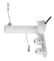
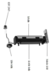
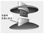
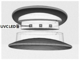
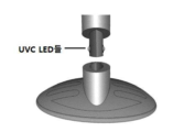
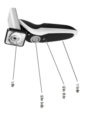
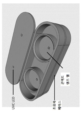
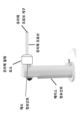
따라서, 일 양태에서, 본 발명은 베이스 컴포넌트 및 헤드 컴포넌트를 포함하는 치료 디바이스를 특징으로 하며, 헤드 컴포넌트는 원위 부분과 근위 부분을 갖고, 헤드 컴포넌트의 원위 부분은 피험자의 눈꺼풀과 접촉하도록 구성되고, 헤드 컴포넌트의 근위 부분은 베이스 컴포넌트에 부착되도록 구성된다. 헤드 컴포넌트의 원위 부분은 자외선 C(UVC) 방사선 소스, 적외선(IR) 방사선 소스 및 초음파 소스를 포함하는 복수의 에너지 소스들로부터 치료 용량의 에너지를 전달하도록 구성될 수 있다. 복수의 에너지 소스들은 헤드 컴포넌트의 원위 부분이 눈꺼풀과 접촉할 때 피험자의 눈꺼풀에 미리 결정된 파워로 치료 용량의 에너지를 전달하도록 구성될 수 있다.Accordingly, in one aspect, the invention features a treatment device comprising a base component and a head component, the head component having a distal portion and a proximal portion, the distal portion of the head component being configured to contact an eyelid of a subject; A proximal portion of the head component is configured to be attached to the base component. The distal portion of the head component may be configured to deliver a therapeutic dose of energy from a plurality of energy sources including an ultraviolet C (UVC) radiation source, an infrared (IR) radiation source, and an ultrasound source. The plurality of energy sources may be configured to deliver a therapeutic dose of energy at a predetermined power to the eyelid of the subject when the distal portion of the head component contacts the eyelid.
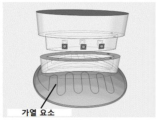
일부 실시예에서, 디바이스는 온도 센서를 더 포함한다. 디바이스는 열의 소스를 더 포함할 수 있다. IR 방사선의 소스는 열을 제공하도록 구성될 수 있다. 일부 실시예에서, 열의 소스는 저항 와이어 요소를 포함한다. 일부 실시예에서, 디바이스는 마이크로파 방사선의 소스를 더 포함한다. 일부 실시예에서, 디바이스는 강한 펄스 광의 소스를 더 포함한다. 일부 실시예에서, 디바이스는 눈꺼풀과 디바이스의 접촉을 감지하는 접촉 센서를 더 포함한다.In some embodiments, the device further includes a temperature sensor. The device may further include a source of heat. A source of IR radiation may be configured to provide heat. In some embodiments, the source of heat includes a resistive wire element. In some embodiments, the device further includes a source of microwave radiation. In some embodiments, the device further includes a source of intense pulsed light. In some embodiments, the device further includes a contact sensor that senses contact of the eyelid with the device.
또 다른 양태에서, 본 발명은 베이스 컴포넌트 및 헤드 컴포넌트를 포함하는 치료 디바이스를 특징으로 하며, 헤드 컴포넌트는 원위 부분과 근위 부분을 갖고, 상기 헤드 컴포넌트의 원위 부분은 UVC 방사선의 소스로부터 치료 용량의 UVC 방사선을 피험자의 안구에 전달하도록 구성되고, 헤드 컴포넌트의 근위 부분은 베이스 컴포넌트에 부착되도록 구성된다. 디바이스는 UVC 방사선의 소스와 안구의 치료 사이트 사이의 미리 결정된 거리를 검출하도록 구성된 근접성 결정 요소를 더 포함할 수 있다. 디바이스는 또한 근접성 결정 요소에 의한 미리 결정된 거리의 검출시 신호를 생성하도록 구성된 신호 생성 요소를 포함할 수 있으며, 여기서 신호는 치료 용량의 UVC 방사선을 피험자의 안구에 미리 결정된 파워로 전달하기 위해 UVC 방사선의 소스를 활성화하도록 구성된다. 치료 디바이스는 근위 부분 및 원위 부분을 갖는 광 가이드를 더 포함할 수 있으며, 광 가이드의 근위 부분은 헤드 컴포넌트의 원위 부분에 부착되도록 구성되고, 광 가이드의 원위 부분은 치료 용량의 UVC 방사선을 전달하도록 구성된다.In another aspect, the invention features a treatment device comprising a base component and a head component, the head component having a distal portion and a proximal portion, the distal portion of the head component receiving a therapeutic dose of UVC radiation from a source of UVC radiation. configured to deliver radiation to an eye of a subject, and a proximal portion of the head component configured to be attached to the base component. The device may further include a proximity determining element configured to detect a predetermined distance between the source of UVC radiation and the treatment site on the eye. The device may also include a signal generating element configured to generate a signal upon detection of a predetermined distance by the proximity determining element, wherein the signal is configured to deliver a therapeutic dose of UVC radiation at a predetermined power to an eye of a subject. It is configured to activate the source of The treatment device may further include a light guide having a proximal portion and a distal portion, the proximal portion of the light guide configured to attach to the distal portion of the head component, the distal portion of the light guide to deliver a therapeutic dose of UVC radiation. It consists of
또 다른 양태에서, 본 발명은 베이스 컴포넌트 및 헤드 컴포넌트를 포함하는 소독 디바이스를 특징으로 하며, 헤드 컴포넌트는 원위 부분과 근위 부분을 갖고, 헤드 컴포넌트의 원위 부분은 UVC 방사선의 소스로부터 피험자에게 살균 용량의 UVC 방사선을 전달하도록 구성되고, 헤드 컴포넌트의 근위 부분은 베이스 컴포넌트에 부착되도록 구성된다. 디바이스는 근위 부분 및 원위 부분을 갖는 광 가이드를 더 포함할 수 있으며, 광 가이드의 근위 부분은 헤드 컴포넌트의 원위 부분에 부착되도록 구성되고, 광 가이드의 원위 부분은 소독 용량의 UVC 방사선을 전달하도록 구성된다. 디바이스는 또한 광 가이드의 원위 부분과 피험자의 치료 사이트 사이의 미리 결정된 거리를 검출하도록 구성된 근접성 결정 요소를 포함할 수 있다. 디바이스는 또한 근접성 결정 요소에 의한 미리 결정된 거리의 검출시 신호를 생성하도록 구성된 신호 생성 요소를 포함할 수 있으며, 여기서 신호는 광 가이드를 통해 미리 결정된 파워로 소독 용량을 전달하기 위해 UVC 방사선의 소스를 활성화시키도록 구성된다.In another aspect, the invention features a disinfecting device comprising a base component and a head component, the head component having a distal portion and a proximal portion, wherein the distal portion of the head component transmits a disinfecting dose to a subject from a source of UVC radiation. configured to deliver UVC radiation, and the proximal portion of the head component configured to be attached to the base component. The device may further include a light guide having a proximal portion and a distal portion, the proximal portion of the light guide configured to attach to the distal portion of the head component, the distal portion of the light guide configured to deliver a disinfecting dose of UVC radiation. do. The device may also include a proximity determining element configured to detect a predetermined distance between the distal portion of the light guide and the treatment site of the subject. The device may also include a signal generating element configured to generate a signal upon detection of a predetermined distance by the proximity determining element, wherein the signal directs a source of UVC radiation to deliver a disinfecting dose at a predetermined power through the light guide. configured to activate.
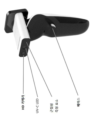
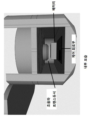
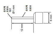
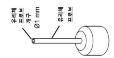
일부 실시예에서, 헤드 컴포넌트는 UVC 방사선의 용량을 조절하도록 구성된 구멍 제어 요소를 포함한다. 구멍 제어 요소는 하나 이상의 제거 가능한 콘들을 포함할 수 있다. 구멍 제어 요소는 헤드 컴포넌트 내에 통합될 수 있다. UVC 방사선의 소스의 구멍은 약 1mm에서 약 50mm일 수 있다(예를 들어, 약 2mm 내지 약 40mm, 약 4mm 내지 약 40mm, 예를 들어, 약 25mm, 예를 들어, 약 4mm).In some embodiments, the head component includes an orifice control element configured to adjust the dose of UVC radiation. The aperture control element may include one or more removable cones. The aperture control element may be integrated into the head component. The aperture of the source of UVC radiation may be from about 1 mm to about 50 mm (eg, from about 2 mm to about 40 mm, from about 4 mm to about 40 mm, such as from about 25 mm, such as about 4 mm).
위의 양태들 중 임의의 것의 일부 실시예에서, UVC 방사선의 소스는 치료 용량의 UVC를 전방 영역, 후방 영역, 유리체 챔버 영역, 망막 영역, 맥락막 사이트, 황반 사이트, 수정체 영역(예를 들어, 안내 수정체 영역), 모양체근 사이트, 시신경 사이트, 손상 사이트, 또는 안구의 이물질에 의해 감염된 사이트에 전달하도록 구성된다. 일부 실시예에서, UVC의 치료 용량은 유리체 절제 요소를 통해 피험자의 안구로 전달되도록 구성된다. 일부 실시예에서, UVC 방사선의 소스는 유리체 절제 요소에 삽입하고 피험자의 안구의 내부 영역에 들어가도록 구성된 광 가이드를 통해 피험자의 안구의 내부 영역에 치료 용량의 UVC 방사선을 전달하도록 구성된다.In some embodiments of any of the above aspects, the source of UVC radiation directs a therapeutic dose of UVC to an anterior region, a posterior region, a vitreous chamber region, a retinal region, a choroidal site, a macular site, a lens region (e.g., an intraocular region). lens area), ciliary muscle site, optic nerve site, site of injury, or site infected by a foreign body in the eye. In some embodiments, the therapeutic dose of UVC is configured to be delivered to the eye of a subject through the vitrectomy element. In some embodiments, the source of UVC radiation is configured to deliver a therapeutic dose of UVC radiation to an inner region of the subject's eye through a light guide inserted into the vitrectomy element and configured to enter the inner region of the subject's eye.
위의 양태들 중 임의의 것의 일부 실시예에서, UVC 방사선의 소스는 치료 용량의 UVC를 상처에 전달하도록 구성된다. 일부 실시예에서, 치료 용량의 UVC는 상처 회복(예를 들어, 회복 속도, 회복 정도 및/또는 흉터 감소)를 개선한다.In some embodiments of any of the above aspects, the source of UVC radiation is configured to deliver a therapeutic dose of UVC to the wound. In some embodiments, a therapeutic dose of UVC improves wound healing (eg, rate, extent of recovery, and/or scar reduction).
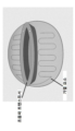
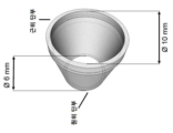
위의 양태들 중 임의의 것의 일부 실시예에서, 디바이스는 헤드 컴포넌트의 원위 부분에 부착하도록 구성된 근위 단부 및 안구와 접촉하여 안정화시키도록 구성된 원위 단부를 포함하는 안구 안정화 요소를 포함한다. 일부 실시예에서, 안구 안정화 요소는 근위 단부에서 제1 직경 및 원위 단부에서 제2 직경을 갖는 원추형으로 형상화된다.In some embodiments of any of the above aspects, the device includes an eye stabilization element comprising a proximal end configured to attach to a distal portion of the head component and a distal end configured to contact and stabilize an eye. In some embodiments, the eye stabilization element is shaped as a cone having a first diameter at the proximal end and a second diameter at the distal end.
일부 실시예에서, 제1 직경은 제2 직경보다 작거나, 제1 직경은 제2 직경보다 크다. 일부 실시예에서, 안구 안정화 요소의 원위 부분은 피험자의 안구를 고정하도록 구성된 복수의 톱니를 포함한다. 일부 실시예에서, 안구 안정화 요소는 UVC 광에 대해 투명하지 않은 재료로 구성된다. 일부 실시예에서, 안구 안정화 요소는 헤드 컴포넌트로부터의 치료 용량의 UVC 방사선이 피험자의 안구의 치료 사이트로 이동할 수 있는 체적을 제공하기 위해 실질적으로 중공이다. 일부 실시예에서, 안구 안정화 요소는 피험자의 안구의 건강한 사이트를 조사하는 UVC 방사선을 차단하도록 구성된다. 일부 실시예에서, 안구 안정화 요소는 일회용이다. 일부 실시예에서, 안구 안정화 요소는 일회용이고 안구 안정화 요소의 재사용을 방지하기 위해 태그(예를 들어, 무선 주파수 식별(RFID))를 포함한다. 일부 실시예에서, 안구 안정화 요소는 살균가능하지 않다. 일부 실시예에서, 안구 안정화 요소는 플라스틱으로 구성된다. 일부 실시예에서, 안구 안정화 요소는 가시광선에 투명하다.In some embodiments, the first diameter is smaller than the second diameter, or the first diameter is larger than the second diameter. In some embodiments, the distal portion of the eye stabilization element includes a plurality of teeth configured to secure an eye of a subject. In some embodiments, the eye stabilizing element is composed of a material that is not transparent to UVC light. In some embodiments, the eye stabilization element is substantially hollow to provide a volume through which a therapeutic dose of UVC radiation from the head component can travel to the treatment site on the eye of the subject. In some embodiments, the eye stabilization element is configured to block UVC radiation irradiating healthy sites of the subject's eye. In some embodiments, the eye stabilization element is disposable. In some embodiments, the eye stabilization element is disposable and includes a tag (eg, radio frequency identification (RFID)) to prevent reuse of the eye stabilization element. In some embodiments, the ocular stabilization component is not sterilizable. In some embodiments, the eye stabilization element is made of plastic. In some embodiments, the eye stabilizing element is transparent to visible light.
또 다른 양태에서, 본 발명은 베이스 컴포넌트 및 헤드 컴포넌트를 포함하는 치료 디바이스를 특징으로 하며, 헤드 컴포넌트는 원위 부분과 근위 부분을 갖고, 헤드 컴포넌트의 원위 부분은 UVA 방사선의 소스로부터 피험자의 안구에 치료 용량의 자외선 A(UVA) 방사선을 전달하도록 구성되고, 헤드 컴포넌트의 근위 부분은 베이스 컴포넌트에 부착되도록 구성된다. 디바이스는 UVA 방사선의 소스와 피험자의 치료 사이트 사이의 미리 결정된 거리를 검출하도록 구성된 근접성 결정 요소를 더 포함할 수 있다. 디바이스는 또한 근접성 결정 요소에 의한 미리 결정된 거리의 검출시 신호를 생성하도록 구성된 신호 생성 요소를 포함할 수 있으며, 상기 신호는 상기 UVA 방사선의 소스를 활성화하여 치료 용량의 UVA 방사선을 피험자의 안구에 미리 결정된 파워로 전달하도록 구성된다.In another aspect, the invention features a treatment device comprising a base component and a head component, the head component having a distal portion and a proximal portion, the distal portion of the head component providing treatment to an eye of a subject from a source of UVA radiation. configured to deliver a dose of ultraviolet A (UVA) radiation, and a proximal portion of the head component configured to be attached to the base component. The device may further include a proximity determining element configured to detect a predetermined distance between the source of UVA radiation and the treatment site of the subject. The device may also include a signal generating element configured to generate a signal upon detection of a predetermined distance by the proximity determining element, the signal activating the source of UVA radiation to preliminarily deliver a therapeutic dose of UVA radiation to an eye of a subject. configured to deliver at the determined power.
일부 실시예에서, 디바이스는 치료 사이트의 이미지를 표시하도록 구성된 이미징 모듈을 더 포함한다.In some embodiments, the device further includes an imaging module configured to display an image of the treatment site.
일부 실시예에서, 디바이스는 슬릿 램프에 장착되도록 구성된다.In some embodiments, the device is configured to be mounted on a slit lamp.
일부 실시 예에서, 디바이스는 전원(예를 들어, 배터리)을 더 포함한다.In some embodiments, the device further includes a power source (eg, a battery).
일부 실시예에서, 디바이스는 예를 들어 제어 버튼과 같은 제어 메커니즘을 더 포함한다. 일부 실시예에서 제어 메커니즘은 베이스 컴포넌트에 있다.In some embodiments, the device further includes a control mechanism, for example a control button. In some embodiments the control mechanism is in the base component.
일부 실시예에서, 근접성 결정 요소는 2개 이상의 레이저들을 포함한다. 근접성 결정 요소는 2개 이상의 레이저들의 수렴 시 신호 생성 요소를 활성화하도록 구성될 수 있다.In some embodiments, the proximity determining element includes two or more lasers. The proximity determining element may be configured to activate the signal generating element upon convergence of two or more lasers.
일부 실시예에서, 신호 생성 요소는 청각, 시각 또는 촉각 신호를 제공하도록 구성된다.In some embodiments, the signal generating element is configured to provide an audible, visual or tactile signal.
또 다른 양태에서, 본 발명은 베이스 컴포넌트 및 헤드 컴포넌트를 포함하는 디바이스를 특징으로 하며, 헤드 컴포넌트는 원위 부분과 근위 부분을 갖고, 헤드 컴포넌트의 원위 부분은 UVC 방사선의 소스로부터 콘택트 렌즈 또는 안경에 UVC 방사의 용량을 전달하도록 구성되고, 헤드 컴포넌트의 근위 부분은 베이스 컴포넌트에 부착되도록 구성된다. 일부 실시예에서, 디바이스는 초음파 소스를 포함하는 콘택트 렌즈 또는 안경 케이스를 더 포함하고, 여기서 콘택트 렌즈 또는 안경 케이스는 헤드 컴포넌트의 원위 부분에 부착되고 초음파의 용량을 전달하도록 구성된다.In another aspect, the invention features a device comprising a base component and a head component, the head component having a distal portion and a proximal portion, wherein the distal portion of the head component transmits UVC radiation from a source of UVC radiation to contact lenses or eyeglasses. configured to deliver a dose of radiation, and a proximal portion of the head component configured to be attached to the base component. In some embodiments, the device further comprises a contact lens or eyeglass case containing the ultrasound source, wherein the contact lens or eyeglass case is attached to the distal portion of the head component and is configured to deliver a dose of ultrasound.
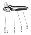
또 다른 양태에서, 본 발명은 복수의 에너지 소스들을 조직 사이트에 전달하기 위한 시스템을 특징으로 한다. 시스템은 베이스 컴포넌트를 포함하고, 베이스 컴포넌트는 근위 부분 및 원위 부분을 갖고, 원위 부분은 UVC 방사선의 소스를 포함하는 제1 헤드; IR 방사선의 소스를 포함하는 제2 헤드; 초음파의 소스를 포함하는 제3 헤드; UVA 방사선의 소스를 포함하는 제4 헤드; UVC 방사선의 소스, IR 방사선의 소스 및 초음파의 소스를 포함하는 제5 헤드; 마이크로파 방사선의 소스 및 강한 펄스 광 소스를 포함하는 제6 헤드 중 2개 이상으로부터 선택되는 복수의 교환가능한 헤드들 중 하나와 매칭되도록 구성된다. 제1 헤드는 에너지 소스와 투여 사이트 사이의 미리 결정된 거리를 검출하도록 구성된 근접성 결정 요소, 근접성 결정 요소에 의해 미리 결정된 거리가 검출되면 신호를 생성하도록 구성된 신호 생성 요소, 에너지 용량을 조절하기 위한 구멍 제어용 모듈, 광 가이드 및 이미징 모듈을 중 하나 이상을 더 포함할 수 있다. 일부 실시예에서, 복수의 에너지 소스들을 조직 사이트에 전달하기 위한 시스템은 마이크로파 방사선의 소스 및 강한 펄스 광의 소스를 포함하고, UVC 방사선, IR 방사선, 초음파, 마이크로파 방사선, 강한 펄스 광은 동시에 투여될 수 있다. 일부 실시예에서, 복수의 에너지 소스들을 조직 사이트에 전달하기 위한 시스템은 마이크로파 방사선의 소스 및 강한 펄스 광의 소스를 포함하고, UVC 방사선, IR 방사선, 초음파, 마이크로파 방사선, 강한 펄스 광은 순차적으로 투여될 수 있다.In another aspect, the invention features a system for delivering a plurality of energy sources to a tissue site. The system includes a first head comprising a base component, the base component having a proximal portion and a distal portion, the distal portion including a source of UVC radiation; a second head comprising a source of IR radiation; a third head including a source of ultrasonic waves; a fourth head comprising a source of UVA radiation; a fifth head comprising a source of UVC radiation, a source of IR radiation and a source of ultrasound; and configured to match one of a plurality of interchangeable heads selected from at least two of the sixth heads comprising a source of microwave radiation and a source of intense pulsed light. The first head includes a proximity determining element configured to detect a predetermined distance between the energy source and the administration site, a signal generating element configured to generate a signal when the predetermined distance is detected by the proximity determining element, and an orifice control to adjust the energy dose. It may further include one or more of a module, a light guide, and an imaging module. In some embodiments, a system for delivering a plurality of energy sources to a tissue site includes a source of microwave radiation and a source of intense pulsed light, wherein UVC radiation, IR radiation, ultrasound, microwave radiation, and intense pulsed light may be administered simultaneously. there is. In some embodiments, a system for delivering a plurality of energy sources to a tissue site includes a source of microwave radiation and a source of intense pulsed light, wherein UVC radiation, IR radiation, ultrasound, microwave radiation, and intense pulsed light are administered sequentially. can
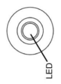
위의 양태들 중 임의의 양태의 일부 실시예에서, UVC 방사선의 소스는 LED를 포함한다. 일부 실시예에서, UVC 방사선의 소스는 복수의 LED들을 포함한다. 일부 실시예에서, UVC 방사선은 약 100nm 내지 약 290nm(예를 들어, 약 200nm 내지 약 290nm, 예를 들어, 약 220nm 내지 약 290nm, 예를 들어, 약 240nm 내지 약 280nm, 예를 들어, 약 250nm 내지 약 280 또는 약 260nm 내지 약 280nm, 예를 들어, 약 254nm, 약 265nm, 또는 약 275nm)의 피크 파장을 포함한다. 일부 실시예에서, UVC 방사선은 약 20mW/cm2 내지 약 1,000mW/cm2의 방사선 강도를 갖는다.In some embodiments of any of the above aspects, the source of UVC radiation comprises an LED. In some embodiments, the source of UVC radiation includes a plurality of LEDs. In some embodiments, the UVC radiation is between about 100 nm and about 290 nm (eg, between about 200 nm and about 290 nm, such as between about 220 nm and about 290 nm, such as between about 240 nm and about 280 nm, such as about 250 nm to about 280 or about 260 nm to about 280 nm, eg, about 254 nm, about 265 nm, or about 275 nm). In some embodiments, the UVC radiation has a radiation intensity of about 20 mW/cm 2 to about 1,000 mW/cm 2 .
위의 양태들 중 임의의 양태의 일부 실시예에서, UVA 방사선의 소스는 LED를 포함한다. 일부 실시예에서, UVA 방사선의 소스는 복수(예를 들어, 1, 2, 3, 4, 5, 6, 7, 8, 9, 10개 또는 그 이상)의 LED들을 포함한다. UVA 방사선은 약 315nm 내지 약 400nm, 예를 들어 약 365nm 또는 약 370nm의 파장을 가질 수 있다. 일부 실시예에서, UVA 방사선은 약 0.5mW/cm2 내지 약 100mW/cm2, 예를 들어, 약 1mW/cm2 내지 약 90mW/cm2, 약 2mW/cm2 내지 약 80mW/cm2, 약 5mW/cm2 내지 약 70mW/cm2, 약 10mW/cm2 내지 약 60mW/cm2, 약 15mW/cm2 내지 약 50mW/cm2, 약 20mW/cm2 내지 약 45mW/cm2, 약 25mW/cm2 내지 약 35mW/cm2의 방사선 강도를 갖는다. 일부 실시예에서, 헤드 컴포넌트는 UVA 방사선의 용량을 조절하도록 구성된 구멍 제어 요소를 더 포함한다.In some embodiments of any of the above aspects, the source of UVA radiation comprises an LED. In some embodiments, the source of UVA radiation includes a plurality (eg, 1, 2, 3, 4, 5, 6, 7, 8, 9, 10 or more) LEDs. UVA radiation may have a wavelength between about 315 nm and about 400 nm, such as about 365 nm or about 370 nm. In some embodiments, the UVA radiation is between about 0.5 mW/cm 2 and about 100 mW/cm 2 , eg between about 1 mW/cm 2 and about 90 mW/cm 2 , between about 2 mW/cm 2 and about 80 mW/cm 2 , about 5 mW/cm 2 to about 70 mW/cm 2 , about 10 mW/cm 2 to about 60 mW/cm 2 , about 15 mW/cm 2 to about 50 mW/cm 2 , about 20 mW/cm 2 to about 45 mW/cm 2 , about 25 mW/cm 2 cm 2 to about 35 mW/cm 2 radiation intensity. In some embodiments, the head component further includes an aperture control element configured to adjust the dose of UVA radiation.
일부 실시예에서, IR 방사선의 소스는 LED를 포함한다. IR 방사선의 소스는 복수의 LED들을 포함할 수 있다. IR 방사선은 약 750nm 내지 약 1,000,000nm의 피크 파장을 포함한다. IR 방사선은 약 20mW/cm2 내지 약 1,000mW/cm2의 방사선 강도를 가질 수 있다.In some embodiments, the source of IR radiation includes an LED. The source of IR radiation may include a plurality of LEDs. IR radiation includes a peak wavelength between about 750 nm and about 1,000,000 nm. The IR radiation may have a radiation intensity of about 20 mW/cm 2 to about 1,000 mW/cm 2 .
일부 실시예에서, 초음파는 약 1MHz 내지 약 10MHz의 주파수를 갖는다.In some embodiments, ultrasound has a frequency between about 1 MHz and about 10 MHz.
위의 양태들 중 임의의 것의 일부 실시예에서, 헤드 컴포넌트 및 베이스 컴포넌트는 일체형이다.In some embodiments of any of the above aspects, the head component and base component are integral.
위의 양태들 중 임의의 것의 일부 실시예에서, 헤드 컴포넌트 및 베이스 컴포넌트는 분리가능하다.In some embodiments of any of the above aspects, the head component and base component are separable.
또 다른 양태에서, 본 발명은 본 명세서에 기재된 바와 같은 디바이스를 제공하고 헤드 컴포넌트의 원위 부분이 눈꺼풀에 접촉하도록 허용하고, 다수의 에너지 소스들로부터의 치료 용량의 에너지를 눈꺼풀에 투여함으로써 안검염 또는 마이봄선 질환(MGD)을 치료하는 방법을 특징으로 한다.In another aspect, the present invention provides a device as described herein and allows a distal portion of a head component to contact the eyelid, administering a therapeutic dose of energy from multiple energy sources to the eyelid, thereby treating blepharitis or miosis. A method for treating spring gland disease (MGD) is characterized.
일부 실시예에서, UVC 방사선, IR 방사선, 초음파, 마이크로파 방사선 및 강한 펄스 광이 동시에 투여될 수 있다. 대안적으로, 일부 실시예에서, UVC 방사선, IR 방사선, 초음파, 마이크로파 방사선 및 강한 펄스 광은 순차적으로 투여될 수 있다.In some embodiments, UVC radiation, IR radiation, ultrasound, microwave radiation and intense pulsed light may be administered simultaneously. Alternatively, in some embodiments, UVC radiation, IR radiation, ultrasound, microwave radiation and intense pulsed light may be administered sequentially.
일부 실시예에서, 방법은 열을 전달하는 단계를 더 포함한다.In some embodiments, the method further includes transferring heat.
또 다른 양태에서, 본 발명은 본 명세서에 설명된 디바이스를 제공하고 치료 사이트에 근접하게 장치를 배치함으로써 안구 감염(예를 들어 안내염), 암(예를 들어 눈꺼풀암 또는 안구암)을 치료하는 방법을 특징으로 한다. 방법은 근접성 결정 요소에 의해 미리 결정된 거리를 검출하는 단계, 신호 생성 요소에 의해 신호를 생성하여 UVC 방사선의 소스를 활성화하는 단계, 및 치료 용량의 UVC 방사선을 눈꺼풀 또는 안구의 치료 사이트에 투여하는 단계를 포함할 수 있다.In another aspect, the present invention provides a device as described herein for treating an eye infection (e.g. endophthalmitis), cancer (e.g. eyelid cancer or eye cancer) by providing the device and placing the device proximate to the treatment site. characterize the method. The method includes detecting a predetermined distance by a proximity determining element, generating a signal by a signal generating element to activate a source of UVC radiation, and administering a therapeutic dose of UVC radiation to a treatment site on the eyelid or eye. can include
또 다른 양태에서, 본 발명은 본 명세서에 기재된 바와 같은 디바이스를 제공하고 디바이스를 치료 사이트에 근접하게 위치시키고, 근접성 결정 요소에 의해 미리 결정된 거리를 검출하고, 신호 생성 요소에 의해 신호를 생성하여 UVC 방사선의 소스를 활성화하고, 및 치료 용량의 UVC 방사선을 치료 사이트에 투여함으로써 암을 치료하는 방법을 특징으로 한다.In another aspect, the present invention provides a device as described herein and positioning the device proximate to a treatment site, detecting a predetermined distance by a proximity determining element, and generating a signal by a signal generating element to detect UVC A method of treating cancer by activating a source of radiation and administering a therapeutic dose of UVC radiation to a treatment site is characterized.
일부 실시예에서, 암은 눈꺼풀 또는 안구암이다. 일부 실시예에서, 암은 안내 흑색종, 망막모세포종, 포도막 흑색종, 결막 흑색종, 안와암 또는 부속기암이다.In some embodiments, the cancer is eyelid or eye cancer. In some embodiments, the cancer is intraocular melanoma, retinoblastoma, uveal melanoma, conjunctival melanoma, orbital cancer, or adnexal cancer.
본 명세서에 기재된 임의의 양태의 일부 실시예에서, 디바이스 및 방법은 예를 들어 암성 또는 전암성 세포를 포함하는 암, 종양형성 및/또는 형성이상을 치료하는 데 사용될 수 있다.In some examples of any aspect described herein, the devices and methods may be used to treat cancer, tumorigenesis and/or dysplasia, including, for example, cancerous or precancerous cells.
또 다른 양태에서, 본 발명은 본 명세서에 기술된 바와 같은 디바이스를 제공하고 광 가이드를 치료 사이트에 근접하게 위치시킴으로써 피험자의 조직을 소독하는 방법을 특징으로 한다. 방법은 근접성 결정 요소에 의해 미리 결정된 거리를 검출하는 단계, 신호 생성 요소에 의해 신호를 생성하여 UVC 방사선의 소스를 활성화하는 단계, 및 광 가이드를 통해 피험자 조직의 치료 사이트에 치료 용량의 UVC 방사선을 투여하는 단계를 포함할 수 있다.In another aspect, the invention features a method of disinfecting tissue of a subject by providing a device as described herein and positioning a light guide proximate to a treatment site. The method includes detecting a predetermined distance by a proximity determining element, generating a signal by a signal generating element to activate a source of UVC radiation, and directing a therapeutic dose of UVC radiation to a treatment site in a tissue of a subject through a light guide. administration may be included.
일부 실시예에서, 조직은 안구, 비강, 구강, 피부 조직 및 내강으로부터 선택된다. 일부 실시예에서, 피험자는 세균 감염(예를 들어, 클라미디아 트라코마티스, 폐렴연쇄구균, 헤모필루스 인플루엔자), 곰팡이 감염, 아메바 감염, 기생충 감염(예를 들어, 톡소카라, 톡소플라즈마, 감염성 망막염), 또는 바이러스 감염(예를 들어, 호흡기 세포융합 바이러스, 인플루엔자 바이러스 또는 SARS-CoV2와 같은 호흡기 감염)을 갖거나 가질 것으로 의심된다. 일부 실시예에서, 피험자는 여드름 및/또는 주사성좌창을 갖는다. 일부 실시양태에서, 피험자는 예를 들어 헬리코박터 파일로리에 의해 유발된 궤양을 갖는다. 일부 실시예에서 피험자는 헤르페스 바이러스 감염을 갖거나 가질 것으로 의심된다. 일부 실시예에서 대상체는 인간 면역결핍 바이러스 감염을 갖거나 가질 것으로 의심된다. 일부 실시예에서 헤르페스 바이러스 감염은 상피 조직, 예를 들어 생식기 조직, 입술 또는 피부의 다른 부분에 위치한다. 일부 실시예에서, 피험자는 인간 유두종 바이러스 감염을 갖거나 가질 것으로 의심된다. 일부 실시예에서, 인간 유두종 바이러스 감염은 자궁경부의 조직에 위치한다.In some embodiments, the tissue is selected from ocular, nasal, oral, skin tissue, and lumen. In some embodiments, the subject has a bacterial infection (eg, Chlamydia trachomatis, Streptococcus pneumoniae, Haemophilus influenzae), a fungal infection, an amoeba infection, a parasitic infection (eg, Toxocara, Toxoplasma, infectious retinitis), or Has or is suspected of having a viral infection (eg, respiratory syncytial virus, influenza virus, or respiratory infection such as SARS-CoV2). In some embodiments, the subject has acne and/or rosacea. In some embodiments, the subject has an ulcer caused, for example, by Helicobacter pylori. In some embodiments the subject has or is suspected of having a herpes virus infection. In some embodiments the subject has or is suspected of having a human immunodeficiency virus infection. In some embodiments, the herpes virus infection is located in an epithelial tissue, such as genital tissue, lips, or other part of the skin. In some embodiments, the subject has or is suspected of having a human papillomavirus infection. In some embodiments, the human papillomavirus infection is located in tissue of the cervix.
또 다른 양태에서, 본 발명은 본 명세서에 기술된 바와 같은 디바이스를 제공하고 디바이스를 치료 사이트에 근접하게 위치시킴으로써 피험자의 각막 확장증(예를 들어, 원추각막)을 치료하는 방법을 특징으로 하며, 여기서 피험자는 광활성화제의 용량을 투여받았다. 적합한 광활성화제는 리보플라빈, 로즈뱅갈, 포르피린계 감광제, 솔라렌, 퀴논, 안트라사이클린, 안트라세네디온, 크산텐, 플루오레세인, 로다민, 프탈레인, 시아닌, 칼코게나피릴륨 염료, 트리아릴메탄 염료, 페노티아진, 페녹사진, 아크리딘, 하이페리신, 니코틴아미드 아데닌 디뉴클레오티드 포스페이트(NADPH), 5-아미노레불린산, 시프로플록사신 및 퀴닌을 포함하지만 이에 제한되지 않는다. 광활성화제는 치료 사이트에 투여될 수 있다. 일부 실시예에서, 방법은 근접성 결정 요소에 의해 미리 결정된 거리를 검출하는 단계, 신호 생성 요소에 의해 신호를 생성하여 UVA 방사선의 소스를 활성화하는 단계 및 치료 용량의 UVA 방사선을 안구의 치료 사이트에 투여하는 단계를 포함한다.In another aspect, the invention features a method of treating ectasia of the cornea (e.g., keratoconus) in a subject by providing a device as described herein and positioning the device proximate to a treatment site, wherein Subjects were administered a dose of photoactivator. Suitable photoactivators include riboflavin, rose bengal, porphyrinic photosensitizers, psoralen, quinones, anthracycline, anthracenedione, xanthene, fluorescein, rhodamine, phthalein, cyanine, chalcogenapryllium dyes, triarylmethane dyes , phenothiazine, phenoxazine, acridine, hypericin, nicotinamide adenine dinucleotide phosphate (NADPH), 5-aminolevulinic acid, ciprofloxacin and quinine. A photoactivator can be administered to the treatment site. In some embodiments, a method includes detecting a predetermined distance by a proximity determining element, generating a signal by a signal generating element to activate a source of UVA radiation, and administering a therapeutic dose of UVA radiation to a treatment site on the eye. It includes steps to
또 다른 양태에서, 본 발명은 본 명세서에 기술된 디바이스를 제공하는 단계, 콘택트 렌즈 또는 안경을 케이스에 넣는 단계, 콘택트 렌즈 또는 안경에 UVC 방사선 및 초음파 소스를 투여하는 단계를 포함하는 콘택트 렌즈 또는 안경을 살균하는 방법을 특징으로 한다. 일부 실시예에서, UVC 방사선 및 초음파는 동시에 투여된다. 일부 실시예에서, UVC 방사선 및 초음파는 순차적으로 투여된다.In another aspect, the present invention provides a contact lens or eyeglass device comprising the steps of providing a device as described herein, placing the contact lens or eyeglasses in a case, and administering UVC radiation and an ultrasound source to the contact lenses or eyeglasses. It is characterized by a method of sterilizing. In some embodiments, UVC radiation and ultrasound are administered simultaneously. In some embodiments, UVC radiation and ultrasound are administered sequentially.
또 다른 양태에서, 본 발명은, UVC 방사선의 소스로부터 피험자의 안구를 향해 치료 용량의 UVC 방사선을 지향시키도록 구성된, 근위 단부 및 원위 단부를 갖는 콘택트 렌즈를 특징으로 한다. 일부 실시예에서, 콘택트 렌즈는 UVC 방사선의 소스를 포함한다. 일부 실시예에서, UVC 방사선의 소스는 LED를 포함한다. 일부 실시예에서, UVC 방사선의 소스는 복수(예를 들어, 1, 2, 3, 4, 5, 6, 7, 8, 9, 10개, 또는 그 이상)의 LED들을 포함한다. 일부 실시예에서, UVC 방사선의 소스는 복수의 표면 장착 디바이스(SMD) LED들을 포함한다. 일부 실시예에서, 복수의 LED들은 콘택트 렌즈에 부착되도록 구성되거나, 렌즈 내에 통합되도록 구성되거나, 렌즈를 통해 포커싱되도록 구성된다. 일부 실시예에서, 콘택트 렌즈의 근위 단부는 피험자의 안구와 접촉하도록 구성되고 원위 단부는 UVC 방사선의 외부 소스와 매칭되도록 구성된다. 일부 실시예에서, UVC 방사선의 외부 소스는 치료 용량의 UVC을 광 가이드를 통해 콘택트 렌즈의 원위 단부에 전달한다. 일부 실시예에서, UVC 방사선은 약 100nm 내지 약 290nm(예를 들어, 약 200nm 내지 약 290nm, 예를 들어, 약 220nm 내지 약 290nm, 예를 들어, 약 240nm 내지 약 280nm, 예를 들어, 약 250nm 내지 약 280 또는 약 260nm 내지 약 280nm, 예를 들어, 약 254nm, 약 265nm, 또는 약 275nm)의 피크 파장을 포함한다. 일부 실시예에서, UVC 방사선은 약 20mW/cm2 내지 약 1,000mW/cm2의 방사선 강도를 갖는다. 일부 실시예에서, 콘택트 렌즈는 배터리, 에너지 전송 안테나, 태양 전지, 관성 파워 하베스터 또는 전기 플러그인 전원을 포함한다.In another aspect, the invention features a contact lens having a proximal end and a distal end configured to direct a therapeutic dose of UVC radiation from a source of UVC radiation toward an eye of a subject. In some embodiments, the contact lens includes a source of UVC radiation. In some embodiments, the source of UVC radiation includes an LED. In some embodiments, the source of UVC radiation includes a plurality (eg, 1, 2, 3, 4, 5, 6, 7, 8, 9, 10, or more) LEDs. In some embodiments, the source of UVC radiation includes a plurality of Surface Mount Device (SMD) LEDs. In some embodiments, the plurality of LEDs are configured to be attached to a contact lens, integrated into the lens, or configured to be focused through the lens. In some embodiments, the proximal end of the contact lens is configured to contact the subject's eye and the distal end is configured to match an external source of UVC radiation. In some embodiments, an external source of UVC radiation delivers a therapeutic dose of UVC through the light guide to the distal end of the contact lens. In some embodiments, the UVC radiation is between about 100 nm and about 290 nm (eg, between about 200 nm and about 290 nm, such as between about 220 nm and about 290 nm, such as between about 240 nm and about 280 nm, such as about 250 nm to about 280 or about 260 nm to about 280 nm, eg, about 254 nm, about 265 nm, or about 275 nm). In some embodiments, the UVC radiation has a radiation intensity of about 20 mW/cm 2 to about 1,000 mW/cm 2 . In some embodiments, the contact lens includes a battery, an energy transmission antenna, a solar cell, an inertial power harvester, or an electrical plug-in power source.
또 다른 양태에서, 본 발명은 본 명세서에 기재된 바와 같은 UVC 방사선의 소스를 갖는 콘택트 렌즈를 제공하는 단계, 안구 감염 사이트에 콘택트 렌즈를 배치하는 단계 및 치료 용량의 UVC 방사선을 눈꺼풀 또는 안구의 치료 사이트에 투여하는 단계를 포함하는 안구 감염을 치료하는 방법을 특징으로 한다.In another aspect, the present invention provides a contact lens having a source of UVC radiation as described herein, placing the contact lens at a site of infection of the eye and applying a therapeutic dose of UVC radiation to the eyelid or treatment site of the eye. characterized by a method of treating an ocular infection comprising the step of administering to.
또 다른 양태에서, 본 발명은 본 명세서에 기술된 치료 디바이스를 제공하는 단계 및 상처에 치료 용량의 UVC 방사선을 투여하는 단계를 포함하는 피험자의 상처를 치료하는 방법을 특징으로 한다.In another aspect, the invention features a method of treating a wound in a subject comprising providing a treatment device as described herein and administering a therapeutic dose of UVC radiation to the wound.
정의Justice
본 발명의 이해를 용이하게 하기 위해, 다수의 용어들이 아래에 정의된다. 본 명세서에서 정의된 용어는 본 발명과 관련된 분야에서 통상의 지식을 가진 사람이 일반적으로 이해하는 의미를 갖는다. 단수표현("a", "an" 및 "the")과 같은 용어는 단일 엔티티만을 지칭하려는 것이 아니라 설명을 위해 특정 예를 사용할 수 있는 일반적인 클래스를 포함한다. 본 명세서에서 용어는 본 발명의 특정 실시예를 설명하기 위해 사용되지만, 그들의 사용은 청구범위에 요약된 것을 제외하고는 본 발명을 제한하지 않는다.To facilitate understanding of the present invention, a number of terms are defined below. Terms defined herein have meanings commonly understood by a person of ordinary skill in the field related to the present invention. Terms such as "a", "an" and "the" are not intended to refer to single entities only, but include generic classes whose specific examples may be used for illustrative purposes. Although terminology is used herein to describe specific embodiments of the invention, their use does not limit the invention except as outlined in the claims.
본 명세서에서 사용되는 바와 같이, "약"이라는 용어는 기술되는 값보다 10% 이상 또는 이하인 값을 의미한다.As used herein, the term “about” means a value that is 10% more or less than the stated value.
본 명세서에서 사용되는 용어 "암(cancer)"은 조절되지 않는 세포 분열 및 세포가 전이되거나 추가 사이트에서 새로운 성장을 확립하는 능력에 의해 유발되는 질병을 의미한다. 용어 암은 예를 들어 백혈병, 정상피종, 흑색종, 기형종, 림프종, 신경모세포종, 신경교종, 직장암, 자궁내막암, 신장암, 부신암, 갑상선암, 혈액암, 피부암, 뇌암, 자궁경부암, 대장암, 간암, 대장암, 위암, 대장암, 두경부암, 위장관암, 림프절암, 식도암, 대장암, 췌장암, 귀, 코와 인후암(ENT), 유방암, 전립선암, 자궁암, 난소암, 폐암 및 이들의 전이를 포함한다. 이의 예는 폐 암종, 유방 암종, 전립선 암종, 결장 암종, 신장 세포 암종, 자궁경부 암종, 또는 상기 기재된 암 또는 종양 유형으로부터의 전이이다. 본 발명에 따른 용어 암은 또한 암 전이 및/또는 주변 조직의 암, 예를 들어 안와암 또는 부속기암을 포함한다. 본 명세서에서 사용된 바와 같이, 암은 또한 예를 들어 암성 및 전암성 세포 또는 조직을 포함하는 종양형성(neoplasia) 및 형성이상(dysplasia)을 포함한다.As used herein, the term "cancer" refers to a disease caused by unregulated cell division and the ability of cells to metastasize or establish new growth at additional sites. The term cancer includes, for example, leukemia, seminoma, melanoma, teratoma, lymphoma, neuroblastoma, glioma, rectal cancer, endometrial cancer, kidney cancer, adrenal cancer, thyroid cancer, hematological cancer, skin cancer, brain cancer, cervical cancer, colon cancer cancer, liver cancer, colon cancer, stomach cancer, colorectal cancer, head and neck cancer, gastrointestinal cancer, lymph node cancer, esophageal cancer, colorectal cancer, pancreatic cancer, ear, nose and throat cancer (ENT), breast cancer, prostate cancer, uterine cancer, ovarian cancer, lung cancer and these contains the transition of Examples thereof are lung carcinoma, breast carcinoma, prostate carcinoma, colon carcinoma, renal cell carcinoma, cervical carcinoma, or metastases from the cancer or tumor types described above. The term cancer according to the present invention also includes cancer metastasis and/or cancer of surrounding tissues, eg orbital cancer or adnexal cancer. As used herein, cancer also includes neoplasia and dysplasia involving, for example, cancerous and precancerous cells or tissues.
본 명세서에서 사용되는 "소독 에너지 용량"이라는 용어는 예를 들어 타겟 사이트의 미생물 로드(예를 들어, 박테리아 로드, 진균, 원생동물, 기생충 또는 바이러스 로드)를 줄이기 위해 적절한 치료 요법에 사용될 때 의도된 소독 효과를 달성하는 데 적합한 전자기 에너지(예를 들어, UV), 기계적 에너지(예를 들어, 초음파 에너지), 열 에너지 또는 이들의 조합의 양을 의미한다.As used herein, the term "disinfection energy capacity" is intended when used in an appropriate treatment regimen, for example to reduce the microbial load (eg bacterial load, fungal, protozoal, parasitic or viral load) of the target site. An amount of electromagnetic energy (eg UV), mechanical energy (eg ultrasonic energy), thermal energy or a combination thereof suitable to achieve a disinfecting effect.
본 명세서에서 사용되는 바와 같이, "에너지 가이드"라는 용어는 임의의 종류의 에너지(예를 들어, 전자기 에너지, 기계적 에너지, 열 에너지)를 일 단부에서 다른 단부로 전달할 수 있는 임의의 요소를 의미한다. 일 실시예에서 광 가이드는 광섬유일 수 있다. 잘 알려진 광섬유에는 용융 실리카, 순수 실리카, 유기실리콘, 중공 튜브, 클래드 및 섬유들이 단일 또는 다발인 클래드되지 않은 섬유로 만들어진 광섬유를 포함한다. 광섬유는 SrNbO3와 같은 투명한 전도성 재료로도 만들 수 있다. 다른 광섬유는 알코올, 에테르, 알데하이드, 케톤 및 유효 파장을 송신하기에 적합한 기타 액체와 같은 물 기반 또는 기타 희석제인 액체 섬유를 포함하며 일부는 적외선 에너지를 포함한 열 에너지를 감소시킬 수 있다.As used herein, the term "energy guide" means any element capable of transferring energy of any kind (eg, electromagnetic energy, mechanical energy, thermal energy) from one end to another. . In one embodiment the light guide may be an optical fiber. Well-known optical fibers include optical fibers made of fused silica, pure silica, organosilicon, hollow tubes, clads, and untapped fibers in which the fibers are single or bundled. Optical fibers can also be made from transparent conductive materials such as SrNbO3. Other optical fibers include liquid fibers that are water-based or other diluents such as alcohols, ethers, aldehydes, ketones, and other liquids suitable for transmitting effective wavelengths, and some can reduce thermal energy, including infrared energy.
본 명세서에서 사용되는 "에너지원(energy source)"이라는 용어는 전자기 복사, 기계적 에너지(예를 들어, 소리 또는 초음파), 열 에너지 또는 이들의 임의의 조합의 소스를 의미한다. 에너지원은 다중 소스들을 포함할 수 있으며 에너지원의 에너지는 타겟 사이트에 직접 투여되거나 에너지 가이드를 통해 투여될 수 있다.The term "energy source" as used herein means a source of electromagnetic radiation, mechanical energy (eg, sound or ultrasound), thermal energy, or any combination thereof. The energy source may include multiple sources and the energy of the energy source may be administered directly to the target site or through an energy guide.
본 명세서에서 사용되는 "이미징 모듈(imaging module)"이라는 용어는 비디오 신호를 생성하는 데 사용되는 이미징 요소 및 처리 회로부를 설명한다.The term "imaging module" as used herein describes imaging elements and processing circuitry used to generate a video signal.
본 명세서에서 사용되는 바와 같이, "일체형"이라는 용어는 전체 디바이스의 일부로서, 이와 관련되거나, 이에 속하는 것을 지칭한다; 즉, 전체의 완전성에 필요하고; 함께 전체를 구성하는 부분으로 구성되거나 조성된다.As used herein, the term “integral” refers to a part of, relating to, or belonging to an overall device; That is, it is necessary for the integrity of the whole; It consists of or is made up of parts that together make up a whole.
본 명세서에서 "강한 펄스 광" 또는 "IPL"이라는 용어는 다양한 파장 범위를 가지며 주기적으로 강한 펄스 형태로 방출되는 비레이저 광을 의미한다. 예를 들어, IPL은 약 300 내지 1,200nm의 파장 범위(IPL 디바이스에 따라 다름)의 광으로 주기적으로 강한 펄스 형태로 방출된다. IPL 조사 장비는 대략 300 내지 1,200nm 파장의 광을 방출하는 램프 플래시(lamp flash)를 사용하고 필터에서 방출되는 광의 파장을 제어한다. IPL 에너지는 2 내지 25ms의 펄스 지속시간과 10 내지 500ms의 인터펄스 지연(interpulse delay)이 있는 일련의 단일, 이중 또는 삼중 펄스 시퀀스들로 전달된다. IPL 방사 에너지 밀도의 범위는 5J/cm2에서 60J/cm2이다.In this specification, the term "intense pulsed light" or "IPL" means non-laser light having various wavelength ranges and periodically emitted in the form of strong pulses. For example, IPL emits periodic intense pulses of light in the wavelength range of about 300 to 1,200 nm (depending on the IPL device). IPL irradiation equipment uses a lamp flash that emits light with a wavelength of approximately 300 to 1,200 nm and controls the wavelength of light emitted from a filter. IPL energy is delivered in a series of single, double or triple pulse sequences with pulse durations of 2 to 25 ms and interpulse delays of 10 to 500 ms. The range of IPL radiant energy density is 5 J/cm 2 to 60 J/cm 2 .
본 명세서에서 사용되는 "광 가이드"라는 용어는 입력 단부에서 광을 수신하고 상당한 손실 없이 광을 출력 단부 또는 추출 메커니즘으로 전파하는 물품을 지칭한다. 일반적으로 광 가이드는 내부 전반사 원리로 작동하며, 이에 의해 광 가이드를 통해 이동하는 광은 광 가이드의 재료와 광 가이드를 바로 둘러싸는 재료, 예를 들어 공기, 클래딩 등의 굴절률 차이에 기초하여 광 가이드의 표면에서 반사된다.The term “light guide” as used herein refers to an article that receives light at its input end and propagates it to the output end or extraction mechanism without significant losses. In general, light guides operate on the principle of total internal reflection, whereby light traveling through the light guide is based on a difference in refractive index between the material of the light guide and the material immediately surrounding the light guide, such as air, cladding, and the like. is reflected from the surface of
본 명세서에 사용된 용어 "근접성(proximity) 결정 요소"는 본 명세서에 기재된 디바이스로부터 치료 또는 투여 사이트의 표면까지의 거리를 측정할 수 있는 임의의 디바이스를 지칭한다.As used herein, the term "proximity determining factor" refers to any device capable of measuring the distance from a device described herein to the surface of a treatment or administration site.
본 명세서에서 사용되는 "호흡기 감염"이라는 용어는 예를 들어, 폐, 후두개, 기관, 기관지, 세기관지 또는 폐포와 같은 기도의 하나 이상의 컴포넌트에서 병원성 미생물(예를 들어, 박테리아 및 바이러스)의 침입 및/또는 증식 및/또는 집락화를 포함한다.As used herein, the term “respiratory infection” refers to the invasion and/or infestation of pathogenic microorganisms (e.g., bacteria and viruses) in one or more components of the respiratory tract, such as, for example, the lungs, epiglottis, trachea, bronchi, bronchioles, or alveoli. or proliferation and/or colonization.
본 명세서에서 사용되는 바와 같이, "분리가능한"이라는 용어는 작동 인터페이스에서 연결을 체결하거나 해제함으로써 쉽게 연결되거나 분리될 수 있는 디바이스 컴포넌트, 모듈, 요소 또는 이들의 임의의 변형을 지칭한다.As used herein, the term “detachable” refers to a device component, module, element or any variation thereof that can be readily connected or disconnected by engaging or disconnecting a connection at an operational interface.
본 명세서에서 사용되는 바와 같이, "신호 생성 요소"라는 용어는 예를 들어, 본 명세서에 기술된 디바이스의 근접성 결정 요소에 의해 측정된 바와 같은 측정된 거리 값에 응답하여 검출 가능한 신호(예를 들어, 청각 신호, 시각적 큐, 햅틱 피드백)를 제공할 수 있는 본 명세서에 기술된 바와 같은 디바이스의 컴포넌트를 의미한다.As used herein, the term "signal generating element" refers to a detectable signal (e.g., , audible cues, visual cues, haptic feedback) of a device as described herein.
본 명세서에 사용된 용어 "살균(sterilization)" 및 "소독(disinfection)" 또는 그의 변형은 피험자의 생체 조직 또는 신체 일부 위 또는 내부, 또는 무생물체 위 또는 내부에 있는 미생물(예를 들어, 병원성 및/또는 비병원성)의 로드의 감소를 의미한다. 본 명세서에서 사용되는 이들 용어는 상호교환적으로 사용될 수 있다.As used herein, the terms "sterilization" and "disinfection" or variations thereof refer to microorganisms (e.g., pathogenic and / or non-pathogenic) load reduction. As used herein, these terms may be used interchangeably.
본 명세서에서 사용되는 바와 같이, 용어 "피험자(subject)"는 상태 또는 후유증에 대한 치료가 필요하거나 이에 민감한 인간을 포함하는 포유동물을 지칭한다. 피험자는 개, 고양이, 돼지, 소, 양, 염소, 말, 쥐, 생쥐 및 인간을 포함할 수 있다. "피험자"라는 용어는 모든 면에서 정상적인 개인을 배제하지 않는다.As used herein, the term "subject" refers to a mammal, including a human, in need of treatment for, or susceptible to, a condition or sequelae. Subjects may include dogs, cats, pigs, cows, sheep, goats, horses, rats, mice and humans. The term "subject" does not exclude individuals who are normal in all respects.
본 명세서에서 "충분한 거리 및 시간"이란 치료 용량의 에너지를 전달하기 위해 디바이스에 의해 생성되는 광 또는 기타 에너지 형태(예를 들어, 기계 또는 열)에 노출되는 타겟 사이트(예를 들어, 신체 사이트, 표면 또는 오브젝트)로부터의 시간 및 거리를 의미한다. 일 실시예에서, 이는 약 0.01초 내지 약 30분이다. 일 실시예에서, 셔터는 에너지원으로부터 타겟 사이트로의 에너지의 통로를 열고, 닫고, 조절하기 위해 이용된다. 노출은 에너지원의 단부로부터 직접 이루어지고 또는 특히 치료 용량의 에너지를 피험자의 피부를 통해 또는 직접 신체의 내강으로 투여하기 위해 에너지 가이드의 단부에서 에너지 가이드(예를 들어, 광 가이드)를 통해 확장될 수 있다.As used herein, "a sufficient distance and time" means a target site (eg, a body site, a site exposed to light or other form of energy (eg, mechanical or thermal) generated by the device to deliver a therapeutic dose of energy). time and distance from a surface or object). In one embodiment, this is from about 0.01 seconds to about 30 minutes. In one embodiment, shutters are used to open, close, and modulate the passage of energy from the energy source to the target site. The exposure may be direct from the end of the energy source or extended through an energy guide (eg, light guide) at the end of the energy guide, in particular to deliver a therapeutic dose of energy through the skin of the subject or directly into a lumen of the body. can
본 명세서에서 사용되는 용어 "치료 에너지 용량"은 예를 들어, 질병의 증상 또는 상태의 중증도를 감소시키기 위해 적절한 치료 요법에 사용될 때 의도된 치료 효과를 달성하기에 적합한 전자기 에너지, 기계적 에너지(예를 들어, 초음파 에너지), 열 에너지 또는 이들의 조합의 양을 의미한다. 용량은 적용된 에너지의 양이 종양 또는 전이의 성장이 느려지거나 멈추거나 종양 또는 전이의 크기 감소가 발견되고 및/또는 환자의 수명이 더 길어지는 효과를 내기에 충분한 경우 암 또는 전이의 치료를 위한 치료 용량으로 간주될 수 있다. 용량은 적용된 에너지의 양이 감염이 느려지거나 멈추거나 환자의 수명이 길어지는 효과를 내기에 충분한 경우 세균 감염, 진균 감염, 원충 감염 또는 바이러스 감염의 치료를 위한 치료 용량으로 간주될 수 있다. 적절한 치료 용량은 일반적으로 예를 들어 치료가 유익하다면 부작용과 독성이 허용되는 경우 치료 효과와 허용되는 독성 사이의 균형을 맞출 것이다.As used herein, the term “therapeutic energy dose” refers to electromagnetic energy, mechanical energy (e.g., suitable for achieving the intended therapeutic effect when used in an appropriate therapeutic regimen to reduce the severity of a symptom or condition of a disease). For example, ultrasonic energy), thermal energy, or a combination thereof. A dose is a treatment for the treatment of cancer or metastasis if the amount of energy applied is sufficient to effect the slowing or stopping of growth of the tumor or metastasis, the finding of a reduction in the size of the tumor or metastasis, and/or the longer lifespan of the patient. capacity can be considered. A dose may be considered a therapeutic dose for the treatment of a bacterial, fungal, protozoal or viral infection if the amount of energy applied is sufficient to have the effect of slowing or stopping the infection or prolonging the patient's lifespan. Appropriate therapeutic doses will generally balance between therapeutic effect and acceptable toxicity, for example where side effects and toxicity are acceptable if the treatment is beneficial.
본 명세서에서 사용되는 용어 "치료"(또한 "치료하다" 또는 "치료하는")는 가장 넓은 의미에서 특정 질병, 장애 또는 상태의 하나 이상의 증상, 피쳐 또는 원인을 부분적으로 또는 완전히 완화, 개선, 재현, 억제, 지연시키거나 중증도를 감소시키고 또는 발생률을 감소시키는 치료제(예를 들어, 자외선)의 임의의 투여를 지칭한다. 일부 실시예에서, 이러한 치료는 관련 질환, 장애 또는 상태의 징후를 나타내지 않는 피험자 또는 질환, 장애 또는 상태의 초기 징후만을 나타내는 피험자에게 투여될 수 있다. 대안적으로 또는 추가적으로, 일부 실시예에서, 관련 질병, 장애 또는 병태의 하나 이상의 확립된 징후를 나타내는 피험자에게 치료가 투여될 수 있다. 일부 실시예에서, 치료는 관련 질병, 장애 또는 병태를 앓는 것으로 진단된 피험자에 대한 것일 수 있다. 일부 실시예에서, 치료는 관련 질병, 장애 또는 병태의 발병 위험 증가와 통계적으로 상관관계가 있는 하나 이상의 감수성 인자를 갖는 것으로 알려진 피험자에 대한 것일 수 있다.As used herein, the term “treatment” (also “treat” or “treating”), in its broadest sense, means partially or completely alleviating, ameliorating, or reproducing one or more symptoms, features, or causes of a particular disease, disorder, or condition. , refers to any administration of a therapeutic agent (eg, ultraviolet light) that inhibits, delays, reduces severity, or reduces incidence. In some embodiments, such treatment may be administered to a subject who does not exhibit symptoms of a related disease, disorder or condition or to a subject who exhibits only early signs of a disease, disorder or condition. Alternatively or additionally, in some embodiments, treatment may be administered to a subject exhibiting one or more established symptoms of a related disease, disorder or condition. In some embodiments, treatment may be for a subject diagnosed as suffering from a related disease, disorder or condition. In some embodiments, treatment may be for a subject known to have one or more susceptibility factors that are statistically correlated with an increased risk of developing a related disease, disorder or condition.
도 1은 치료 디바이스의 제어 측을 도시하는 개략도이다. 베이스 컴포넌트, 제어 버튼 및 교환가능한 헤드 컴포넌트(별표로 표시)가 도시된다.
도 2는 치료 디바이스의 치료 측을 도시하는 개략도이다. 베이스 컴포넌트, UVC LED 소스 및 교환가능한 헤드 컴포넌트(별표로 표시됨)가 도시된다.
도 3은 치료 디바이스 및 충전 도킹 스테이션(charge docking station)의 측 뷰를 도시하는 개략도이다.
도 4는 치료용 전달 디바이스(therapeutic delivery device)의 내부 컴포넌트를 도시하는 개략도이다. 제어 버튼, 제어 회로부, 충전 커넥터, 배터리 및 UVC LED 컴포넌트들이 도시된다.
도 5는 에너지 전달 헤드 컴포넌트를 도시하는 개략도이다. 다중 UVC LED들이 표시되어 있으며 가열 요소와 리드 검경(lid speculum)을 포함하는 모듈과 연결할 수 있다.
도 6은 초음파 트랜스듀서(transducer) 및 가열 요소로 구성되는 에너지 전달 헤드 컴포넌트를 도시하는 개략도이다.
도 7a 내지 7d는 UVC 광, 초음파 및 열을 전달하도록 구성된 에너지 전달 헤드 모듈의 다중 뷰들을 도시하는 개략도이다. 도 7a는 초음파 트랜스듀서를 도시하고, 도 7b는 가열 요소를 도시하고, 도 7c 및 7d는 UVC LED를 도시한다.
도 8은 UVC 광, 초음파 및 열을 전달하도록 구성된 에너지 전달 헤드 모듈을 도시하는 개략도이다.
도 9는 치료 디바이스의 제어 측을 도시하는 개략도이다. 헤드 컴포넌트, 제어 버튼, 파워 버튼 및 베이스 컴포넌트가 도시된다.
도 10은 베이스 컴포넌트 및 헤드 컴포넌트를 포함하는 치료 디바이스의 측 뷰를 도시하는 개략도이다.
도 11은 치료 디바이스의 치료 측의 개략도이다. 이미징 모듈(HD 카메라), UVC LED 소스, 근접성 측정 요소 및 베이스 컴포넌트가 도시된다.
도 12는 치료 디바이스의 제어 측의 개략도이다. 비디오 화면, 헤드 모듈, 제어 버튼, 파워 버튼 및 베이스 컴포넌트가 도시된다.
도 13은 치료 디바이스의 제어 측의 개략도이다. 비디오 화면, 헤드 모듈, 제어 버튼, 파워 버튼 및 베이스 컴포넌트가 도시된다.
도 14는 치료 디바이스의 치료 측의 개략도이다. 이미징 모듈(HD 카메라), UVC LED 소스, 근접성 측정 요소 및 베이스 컴포넌트가 도시된다.
도 15는 치료 디바이스의 제어 측의 개략도이다. 신호 생성 요소(비디오 화면), 제어 버튼, 파워 버튼 및 베이스 컴포넌트가 도시된다.
도 16은 치료 디바이스의 치료 측의 개략도들의 그룹이다. 근접성 측정 요소와 UVA LED들의 어레이가 도시된다.
도 17은 치료 디바이스의 치료 측의 개략도이다. 근접성 측정 요소와 UVA LED들의 어레이가 도시된다.
도 18은 UVC 살균 디바이스의 개략도이다. 다중 UVC LED 소스들, 초음파를 전달하도록 구성된 베이스 컴포넌트 및 콘택트 렌즈 웰이 도시된다.
도 19는 UVC 살균 디바이스의 개략도이다. 다중 UVC LED 소스들, 초음파를 전달하도록 구성된 베이스 컴포넌트 및 콘택트 렌즈 웰이 도시된다.
도 20은 UVC 살균 디바이스의 평면도의 개략도이다. 다중 UVC LED 소스들, 초음파를 전달하도록 구성된 베이스 컴포넌트 및 콘택트 렌즈 웰이 도시된다.
도 21은 UVC 살균 디바이스의 측 뷰의 개략도이다. 초음파와 UVC를 전달하도록 구성된 제어 회로 구획과 배터리 구획이 도시된다.
도 22는 UVC 살균 디바이스의 베이스의 내부 컴포넌트의 개략도이다. 초음파와 UVC를 전달하도록 구성된 제어 회로 구획, 배터리 구획 및 초음파 트랜스듀서가 도시된다.
도 23은 UVC 살균 디바이스의 헤드 컴포넌트의 원위 단부에 연결된 것으로 도시된 유리체 절제 요소(vitrectomy element)의 실시예의 개략도이다. 유리체 프로브(vitreous probe)와 유리체 프로브 개구가 도시된다. 이 실시예에서, UVC 방사선은 유리체 절제 요소의 일 단부에 들어가고 안구의 내부 영역으로 삽입되도록 구성된 유리체 프로브 개구에서 빠져나간다.
도 24a는 직경 6mm의 베이스, 길이 12mm의 유리체 프로브를 갖는 것으로 도시된 유리체 절제 요소의 실시예의 측 뷰의 개략도이며, 유리체 프로브 개구는 직경이 1mm인 것으로 도시되어 있다.
도 24b는 직경 1mm의 유리체 프로브 개구를 갖는 것으로 도시된 유리체 절제 요소의 실시예의 사시도의 개략도이다.
도 25는 안구의 유리체 바디에 UVC 광을 전달하는 광 가이드의 실시예를 도시하는 개략도이다. 바늘을 조합하여 유리체 바디의 일부를 추출할 수 있다.
도 26a 및 26b는 10mm의 근위 단부에서 원위 단부까지의 길이를 갖는 안구 안정화 요소의 실시예의 개략도이다. 원위 단부는 매끄러운 에지로 도시된다. 안구 안정화 요소는 원위 단부보다 근위 단부에서 더 큰 직경을 갖는 원추형으로 도시되어 있다. 원위 단부는 피험자의 안구와 접촉하여 안구를 안정시키고 안구 움직임을 최소화한다. 근위 단부는 디바이스의 헤드 컴포넌트의 원위 단부에 부착되도록 구성된다. 도 27a는 측면도이고 도 27b는 사시도이다. 원위 단부는 6mm의 직경을 갖는 것으로 도시되어 있고 근위 단부는 직경이 10mm인 것으로 도시되어 있다.
도 27a는 안구 안정화 요소의 실시예의 개략도이다. 원위 단부는 매끄러운 에지를 갖는 것으로 도시된다. 안구 안정화 요소는 원위 단부보다 근위 단부에서 더 큰 직경을 갖는 원추형으로 도시되어 있다. 원위 단부는 피험자의 안구와 접촉하여 안구를 안정시키고 안구 움직임을 최소화한다. 근위 단부는 디바이스의 헤드 컴포넌트의 원위 단부에 부착되도록 구성된다.
도 27b는 안구 안정화 요소의 실시예의 개략도이다. 원위 단부는 톱니가 있는 성곽형상의 에지(castellated edge)를 갖는 것으로 도시되어 있다. 안구 안정화 요소는 원위 단부보다 근위 단부에서 더 큰 직경을 갖는 원추형으로 도시되어 있다. 원위 단부는 피험자의 안구와 접촉하여 안구를 안정시키고 안구 움직임을 최소화한다. 근위 단부는 디바이스의 헤드 컴포넌트의 원위 단부에 부착되도록 구성된다.
도 28a는 (예를 들어, 치은염(gingivitis)을 치료하기 위해) 피험자의 입에 UVC의 치료 용량을 전달하는 데 사용되는 광 가이드의 실시예의 개략도이다. 근위 단부에서 원위 단부까지의 길이가 40mm이고 근위 단부에서 직경이 15mm인 이 예시적인 실시예가 도시되어 있다. 광 가이드는 근위 단부에서 디바이스의 헤드 컴포넌트에 부착되도록 구성된다. 광 가이드는 원위 단부에서 UVC LED로 구성된다.
도 28b는 (예를 들어, 치은염을 치료하기 위해) 피험자의 입에 UVC의 치료 용량을 전달하는 데 사용되는 광 가이드의 실시예의 평면도의 개략도이다. UVC LED가 도시된다.
도 28c는 (예를 들어, 치은염을 치료하기 위해) 피험자의 입에 UVC의 치료 용량을 전달하는 데 사용되는 광 가이드의 실시예의 측 뷰의 개략도이다. 근위 및 원위 단부들이 도시되어 있으며 원위 단부에 UVC LED가 있다.
도 28d는 (예를 들어, 치은염을 치료하기 위해) 피험자의 입에 UVC의 치료 용량을 전달하는 데 사용되는 광 가이드의 실시예의 측면도이다. 헤드 컴포넌트에 광 가이드가 부착되며 헤드 컴포넌트뿐만 아니라 베이스 컴포넌트 및 UVC LED에 부착된 광 가이드가 도시되어 있다.1 is a schematic diagram showing the control side of a treatment device. Base components, control buttons and interchangeable head components (marked with asterisks) are shown.
2 is a schematic diagram showing a treatment side of a treatment device. Base components, UVC LED sources and interchangeable head components (marked with asterisks) are shown.
3 is a schematic diagram showing a side view of a treatment device and a charge docking station.
4 is a schematic diagram showing the internal components of a therapeutic delivery device. Control buttons, control circuitry, charging connector, battery and UVC LED components are shown.
5 is a schematic diagram showing energy transfer head components; Multiple UVC LEDs are shown and can be connected with a module containing a heating element and a lid speculum.
6 is a schematic diagram showing an energy transfer head component consisting of an ultrasonic transducer and a heating element.
7A-7D are schematic diagrams showing multiple views of an energy delivery head module configured to deliver UVC light, ultrasound and heat. 7a shows an ultrasonic transducer, FIG. 7b shows a heating element, and FIGS. 7c and 7d show a UVC LED.
8 is a schematic diagram showing an energy delivery head module configured to deliver UVC light, ultrasound and heat.
9 is a schematic diagram showing the control side of the treatment device. A head component, control button, power button and base component are shown.
10 is a schematic diagram showing a side view of a treatment device comprising a base component and a head component.
11 is a schematic diagram of the treatment side of a treatment device. An imaging module (HD camera), UVC LED source, proximity measuring element and base component are shown.
12 is a schematic diagram of the control side of a treatment device. A video screen, head module, control buttons, power button and base components are shown.
13 is a schematic diagram of the control side of a treatment device. A video screen, head module, control buttons, power button and base components are shown.
14 is a schematic diagram of the treatment side of a treatment device. An imaging module (HD camera), UVC LED source, proximity measuring element and base component are shown.
15 is a schematic diagram of the control side of a treatment device. A signal generating element (video screen), a control button, a power button and a base component are shown.
16 is a group of schematic views of the treatment side of a treatment device. A proximity measuring element and an array of UVA LEDs are shown.
17 is a schematic diagram of the treatment side of a treatment device. A proximity measuring element and an array of UVA LEDs are shown.
18 is a schematic diagram of a UVC sterilization device. Multiple UVC LED sources, a base component configured to transmit ultrasound and a contact lens well are shown.
19 is a schematic diagram of a UVC sterilization device. Multiple UVC LED sources, a base component configured to transmit ultrasound and a contact lens well are shown.
20 is a schematic diagram of a top view of a UVC sterilization device. Multiple UVC LED sources, a base component configured to transmit ultrasound and a contact lens well are shown.
21 is a schematic diagram of a side view of a UVC disinfection device. A control circuit compartment configured to deliver ultrasound and UVC and a battery compartment are shown.
22 is a schematic diagram of the internal components of the base of the UVC disinfection device. A control circuit compartment configured to deliver ultrasound and UVC, a battery compartment and an ultrasound transducer are shown.
23 is a schematic diagram of an embodiment of a vitrectomy element shown connected to the distal end of the head component of a UVC disinfection device. A vitreous probe and vitreous probe aperture are shown. In this embodiment, UVC radiation enters one end of the vitrectomy element and exits a vitreous probe aperture configured to be inserted into an interior region of the eye.
24A is a schematic diagram of a side view of an embodiment of a vitrectomy element shown having a 6 mm diameter base, 12 mm long vitreous probe, with the vitreous probe aperture shown having a 1 mm diameter.
24B is a schematic diagram of a perspective view of an embodiment of a vitrectomy element shown having a vitreous probe opening of 1 mm in diameter.
25 is a schematic diagram illustrating an embodiment of a light guide delivering UVC light to the vitreous body of the eye. A combination of needles can be used to extract portions of the vitreous body.
26A and 26B are schematic diagrams of an embodiment of an eye stabilization element having a proximal end to distal end length of 10 mm. The distal end is shown with a smooth edge. The eye stabilization element is shown as a cone with a larger diameter at the proximal end than at the distal end. The distal end contacts the subject's eye to stabilize the eye and minimize eye movement. The proximal end is configured to attach to the distal end of the head component of the device. Fig. 27a is a side view and Fig. 27b is a perspective view. The distal end is shown as having a diameter of 6 mm and the proximal end is shown as having a diameter of 10 mm.
27A is a schematic diagram of an embodiment of an eye stabilization element. The distal end is shown with a smooth edge. The eye stabilization element is shown as a cone with a larger diameter at the proximal end than at the distal end. The distal end contacts the subject's eye to stabilize the eye and minimize eye movement. The proximal end is configured to attach to the distal end of the head component of the device.
27B is a schematic diagram of an embodiment of an eye stabilization element. The distal end is shown with a serrated, castellated edge. The eye stabilization element is shown as a cone with a larger diameter at the proximal end than at the distal end. The distal end contacts the subject's eye to stabilize the eye and minimize eye movement. The proximal end is configured to attach to the distal end of the head component of the device.
28A is a schematic diagram of an embodiment of a light guide used to deliver a therapeutic dose of UVC to the mouth of a subject (eg, to treat gingivitis). This exemplary embodiment is shown with a length of 40 mm from the proximal end to the distal end and a diameter of 15 mm at the proximal end. The light guide is configured to be attached to the head component of the device at its proximal end. The light guide consists of a UVC LED at the distal end.
28B is a schematic diagram of a top view of an embodiment of a light guide used to deliver a therapeutic dose of UVC to the mouth of a subject (eg, to treat gingivitis). A UVC LED is shown.
28C is a schematic diagram of a side view of an embodiment of a light guide used to deliver a therapeutic dose of UVC to a subject's mouth (eg, to treat gingivitis). Proximal and distal ends are shown and there is a UVC LED at the distal end.
28D is a side view of an embodiment of a light guide used to deliver a therapeutic dose of UVC to a subject's mouth (eg, to treat gingivitis). A light guide is attached to the head component and the light guide is shown attached to the head component as well as to the base component and UVC LEDs.
본 발명은 치료 또는 살균 자외선(UV) 방사선을 전달하기 위한 디바이스, 시스템 및 그 사용 방법을 특징으로 한다. 본 명세서에 기술된 디바이스 및 시스템은 안검염, 마이봄선 질환(MGD), 안구암, 안구 감염 및 원추각막과 같은 안구 상태의 치료를 포함하는 다양한 목적을 위해 사용될 수 있다. 본 명세서에 기술된 디바이스는 피험자의 안구, 비강, 구강, 피부 조직 또는 내강과 같은 다양한 조직에 살균 또는 치료 방사선을 제공하는 데 사용될 수 있다. 디바이스는 또한 암(예를 들어, 안구 또는 눈꺼풀 암), 종양형성 및/또는 형성이상을 치료하는 데 사용될 수 있다. 일반적으로, 디바이스는 베이스 컴포넌트 및 그 위에 부착된 헤드 컴포넌트를 포함하고, 헤드 컴포넌트는 치료 또는 살균 UV 방사선(예를 들어, UVA 또는 UVC)을 피험자의 치료 사이트 또는 디바이스에 전달하도록 구성된다. 디바이스는 또한 다기능 방식으로 설계될 수 있으므로, 단일 디바이스가 원하는 목적이나 기능에 따라 각각 사용될 수 있는 복수의 교환가능한 헤드들과 함께 사용될 수 있다. 디바이스 및 시스템의 컴포넌트들은 아래에서 자세히 설명된다.The invention features devices, systems, and methods of use for delivering therapeutic or bactericidal ultraviolet (UV) radiation. The devices and systems described herein may be used for a variety of purposes, including treatment of ocular conditions such as blepharitis, meibomian gland disease (MGD), eye cancer, eye infections, and keratoconus. The devices described herein may be used to deliver bactericidal or therapeutic radiation to a variety of tissues, such as the eye, nasal cavity, oral cavity, skin tissue, or lumen of a subject. The device may also be used to treat cancer (eg, eye or eyelid cancer), tumorigenesis and/or dysplasia. Generally, the device includes a base component and a head component attached thereon, the head component configured to deliver therapeutic or bactericidal UV radiation (eg, UVA or UVC) to a treatment site or device on a subject. The device can also be designed in a multifunctional way, such that a single device can be used with a plurality of interchangeable heads, each of which can be used according to a desired purpose or function. Components of the device and system are described in detail below.
베이스 컴포넌트base component
본 명세서에 기술된 바와 같은 디바이스의 베이스 컴포넌트는 원위 부분 및 근위 부분을 포함하고, 근위 부분은 헤드 컴포넌트를 연결되도록 구성된다. 베이스 컴포넌트는 그 위에 헤드 컴포넌트를 수용하도록 적합하게 구성되도록 임의의 적합한 크기 및 형상을 가질 수 있다. 베이스 컴포넌트는 핸드헬드 디바이스를 쉽게 제어할 수 있도록 인체 공학적 디자인을 가질 수 있다. 예를 들어, 베이스 컴포넌트는 디바이스가 사용자, 예를 들어 의료 서비스 제공자에 의해 쉽게 조작될 수 있도록 핸들을 포함할 수 있다. 베이스 컴포넌트는 현미경, 슬릿 램프, 전원 또는 에너지원(예를 들어, UV(예를 들어, UVA 또는 UVC) IR, 열 및 초음파)과 같은 다른 디바이스 또는 기구에 장착되도록 구성될 수 있다. 베이스 컴포넌트는 헤드 컴포넌트 또는 다른 액세서리 컴포넌트의 부착을 위해 예를 들어 그 원위 부분에 하우징을 포함할 수 있다. 베이스 컴포넌트는 베이스 컴포넌트를 다른 기구, 예를 들어 슬릿 램프에 장착하기 위한 하우징을 포함할 수 있다. 베이스 컴포넌트는 헤드 컴포넌트에 제거 가능하게 부착(예를 들어, 분리가능)하도록 설계될 수 있으며 베이스 컴포넌트와 헤드 컴포넌트는 시스템을 형성한다. 대안적으로, 베이스 컴포넌트는 헤드 컴포넌트와 통합되도록 설계될 수 있다.A base component of a device as described herein includes a distal portion and a proximal portion, the proximal portion being configured to connect the head component. The base component may have any suitable size and shape to be suitably configured to receive a head component thereon. The base component may have an ergonomic design for easy control of the handheld device. For example, the base component may include a handle so that the device can be easily manipulated by a user, such as a healthcare provider. The base component may be configured to mount to other devices or instruments such as microscopes, slit lamps, power sources or energy sources (eg UV (eg UVA or UVC) IR, heat and ultrasound). The base component may include a housing at its distal part, for example, for attachment of a head component or other accessory component. The base component may include a housing for mounting the base component to another fixture, for example a slit lamp. The base component may be designed to be removably attached (eg, releasable) to the head component and the base component and head component form a system. Alternatively, the base component may be designed to be integrated with the head component.
헤드 컴포넌트head component
본 명세서에 기술된 바와 같은 디바이스의 헤드 컴포넌트는 원위 부분 및 근위 부분을 포함하고, 원위 부분은 치료 또는 살균 사이트에 치료 에너지의 소스(예를 들어, UV, IR, 열, 마이크로파, 강한 펄스 광 및/또는 초음파)를 전달하도록 구성된다. 헤드 컴포넌트의 근위 부분은 베이스 컴포넌트에 부착되거나 장착되도록 구성된다. 헤드 컴포넌트는 예를 들어 적절한 사이트(예를 들어, 안구, 눈꺼풀, 비강, 구강, 치아강, 치주 조직, 피부 조직 또는 내강(예를 들어, 위장 내강, 구인두 내강, 생식기 내강 또는 비뇨기 내강))에 치료 에너지를 전달하기 위해 그 기능에 일치하는 임의의 적합한 기하학적 구조를 가질 수 있다. 예를 들어, 눈꺼풀에 치료 에너지를 전달하도록 구성된 디바이스는 피험자의 눈꺼풀 또는 눈꺼풀들의 세트에 일치하도록 구성된 크기 및 형상(예를 들어, 곡률)을 가진 헤드 컴포넌트를 포함할 수 있다. 일부 실시예에서, 헤드 컴포넌트는 치료 사이트와 접촉하도록 구성된 부착물(attachment)을 포함할 수 있다. 일부 실시예에서, 헤드 컴포넌트는 치료용 UV 방사선을 치아, 치아의 일부, 치아 우식증 또는 치아 공동(예를 들어, 근관 또는 발치 절차 동안)에 전달하도록 구성된 광 가이드를 포함한다. 일부 실시예에서, 광 가이드는 치아 또는 치아의 일부가 이전에 제거되었던 영역으로 UV 방사선을 전달하도록 구성된다.The head component of a device as described herein includes a distal portion and a proximal portion, the distal portion being a source of therapeutic energy (e.g., UV, IR, heat, microwave, intense pulsed light and / or ultrasound). A proximal portion of the head component is configured to be attached to or mounted to the base component. The head component may, for example, be placed at an appropriate site (eg eye, eyelid, nasal cavity, oral cavity, dental cavity, periodontal tissue, skin tissue or lumen (eg gastrointestinal lumen, oropharyngeal lumen, genital lumen or urinary lumen)). It may have any suitable geometry consistent with its function to deliver therapeutic energy. For example, a device configured to deliver therapeutic energy to an eyelid may include a head component with a size and shape (eg, curvature) configured to conform to a subject's eyelid or set of eyelids. In some embodiments, the head component may include an attachment configured to contact the treatment site. In some embodiments, the head component includes a light guide configured to deliver therapeutic UV radiation to a tooth, part of a tooth, dental caries, or dental cavity (eg, during a root canal or tooth extraction procedure). In some embodiments, the light guide is configured to deliver UV radiation to an area where a tooth or part of a tooth was previously removed.
헤드 컴포넌트는 치료 에너지의 소스를 수용할 수 있으며, 예를 들어 치료 에너지의 소스(예를 들어, UV)는 헤드 내부 또는 헤드에 통합되어 있다. 대안적으로, 헤드 컴포넌트는 소스를 통해 치료 에너지의 소스를 적용 사이트로 보내는 송신기로서 작용할 수 있다. 일부 실시예에서, 디바이스는 UV 방사선을 전달하기 위한 광 가이드를 더 포함한다. 광 가이드는 헤드 컴포넌트에 부착될 수 있고, 이는 광 가이드를 통해 소스에서 적용 사이트로 치료 에너지를 전달한다.The head component may contain a source of therapeutic energy, for example the source of therapeutic energy (eg UV) is internal to or integrated into the head. Alternatively, the head component may act as a transmitter directing a source of therapeutic energy through the source to the application site. In some embodiments, the device further comprises a light guide for delivering UV radiation. A light guide can be attached to the head component, which delivers the treatment energy from the source to the application site through the light guide.
UV 방사선UV radiation
본 명세서에 기술된 디바이스는 UV 방사선의 소스를 포함한다. UV 방사선은 예를 들어 UVC 방사선, UVA 방사선 또는 이들의 조합일 수 있다. UVC 방사선은 약 100nm 내지 약 280nm(예를 들어, 약 200nm 내지 약 280nm, 예를 들어, 약 220nm 내지 약 280nm, 예를 들어, 약 240nm 내지 약 270nm, 예를 들어, 약 250nm 내지 약 270nm 또는 약 260nm 내지 약 270nm, 예를 들어, 약 254nm, 255nm, 또는 약 265nm)의 파장을 가질 수 있다. UVA 방사선은 약 315nm 내지 약 400nm의 파장을 가질 수 있다. UV 방사선의 소스는 복수의 파장들에서 방사선을 방출하도록 구성될 수 있다. 소스는 선택된 파장에서 방사선을 방출하도록 튜닝 가능하다. UV 방사선의 소스는 적어도 하나의 발광 다이오드(LED) 또는 UV 방사선을 방출하는 복수의 LED들을 포함할 수 있다. 예를 들어, 소스는 UV 방사선을 방출하는 1, 2, 3, 4, 5, 6, 7, 8, 9, 10개 이상의 LED들을 포함할 수 있다. 일 실시예에서, UV 방사선의 소스는 8개의 LED들을 포함한다.The devices described herein include a source of UV radiation. UV radiation can be, for example, UVC radiation, UVA radiation or a combination thereof. UVC radiation is about 100 nm to about 280 nm (e.g., about 200 nm to about 280 nm, e.g., about 220 nm to about 280 nm, e.g., about 240 nm to about 270 nm, e.g., about 250 nm to about 270 nm or about 260 nm to about 270 nm, such as about 254 nm, 255 nm, or about 265 nm). UVA radiation can have a wavelength between about 315 nm and about 400 nm. A source of UV radiation may be configured to emit radiation at a plurality of wavelengths. The source is tunable to emit radiation at a selected wavelength. The source of UV radiation may include at least one light emitting diode (LED) or a plurality of LEDs that emit UV radiation. For example, the source may include 1, 2, 3, 4, 5, 6, 7, 8, 9, 10 or more LEDs that emit UV radiation. In one embodiment, the source of UV radiation includes 8 LEDs.
일부 실시예에서, UV 방사선의 소스는 약 0.005mW 내지 약 50mW(예를 들어, 약 0.005mW 내지 약 5mW, 예를 들어, 약 0.01mW 내지 약 1mW)의 파워 출력을 갖는다. 예를 들어, UV 방사선의 소스는 약 0.005mW 내지 약 0.01mW(예를 들어, 약 0.006mW, 0.007mW, 0.008mW, 0.009mW 또는 0.01mW, 예를 들어, 약 0.01mW 내지 약 0.1mW, 예를 들어, 약 0.02mW, 0.03mW, 0.04mW, 0.05mW, 0.06mW, 0.07mW, 0.08mW, 0.09mW 또는 0.1mW, 예를 들어, 약 0.1mW 내지 약 1mW, 예를 들어, 약 0.2mW, 0.3mW, 0.4mW, 0.5mW, 0.6mW, 0.7mW, 0.8mW, 0.9mW 또는 1mW, 예를 들어, 약 1mW 내지 약 10mW, 예를 들어, 약 2mW, 3W, 4mW, 5mW, 6mW, 7mW, 8mW, 9mW 또는 10mW, 예를 들어, 약 10mW 내지 약 50mW, 예를 들어, 약 15mW, 20mW, 25mW, 30mW, 35mW, 40mW, 45mW 또는 50mW)의 출력을 가질 수 있다. 원하는 파워 출력을 방출하기 위해 소스의 파워가 조정 가능할 수 있다.In some embodiments, the source of UV radiation has a power output between about 0.005 mW and about 50 mW (eg, between about 0.005 mW and about 5 mW, such as between about 0.01 mW and about 1 mW). For example, the source of UV radiation may be between about 0.005 mW and about 0.01 mW (eg, between about 0.006 mW, 0.007 mW, 0.008 mW, 0.009 mW, or 0.01 mW, such as between about 0.01 mW and about 0.1 mW, e.g., between about 0.01 mW and about 0.1 mW). for example about 0.02 mW, 0.03 mW, 0.04 mW, 0.05 mW, 0.06 mW, 0.07 mW, 0.08 mW, 0.09 mW or 0.1 mW, such as from about 0.1 mW to about 1 mW, such as about 0.2 mW; 0.3mW, 0.4mW, 0.5mW, 0.6mW, 0.7mW, 0.8mW, 0.9mW or 1mW, such as from about 1mW to about 10mW, such as about 2mW, 3W, 4mW, 5mW, 6mW, 7mW, 8 mW, 9 mW or 10 mW, eg between about 10 mW and about 50 mW, eg about 15 mW, 20 mW, 25 mW, 30 mW, 35 mW, 40 mW, 45 mW or 50 mW). The power of the source may be adjustable to emit a desired power output.
UV 방사선의 소스는 안구의 전체 표면을 조사하도록 구성될 수 있다. UV 방사선의 소스는 최대 치수가 약 10cm 미만, 예를 들어, 약 9cm, 8cm, 7cm, 6cm, 5cm, 4cm, 3cm, 2cm, 1cm, 0.9cm, 0.8cm, 0.7cm, 0.6cm, 0.5cm, 0.4cm, 0.3cm, 0.2cm 또는 0.1cm 미만인 조직 영역을 조사하도록 구성될 수 있다. 방사선의 소스는 조직의 실질적으로 원형인 구역, 조직의 세장형 구역, 또는 신체 조직의 환형 구역을 조사하도록 구성될 수 있다. 일부 실시예에서, 방사선의 소스는 조사되는 구역의 크기 및/또는 형상을 조정하도록 조정 가능하도록 구성된다. 디바이스는 신체 조직의 한 영역에 걸쳐 UV 방사선을 스캔하도록 구성될 수 있다. 이는 예를 들어 베이스 컴포넌트 또는 그 위의 핸들을 이동시켜 또는 예를 들어, 헤드 컴포넌트에서 회전 또는 이동 컴포넌트에 의해 달성될 수 있다.The source of UV radiation may be configured to illuminate the entire surface of the eye. The source of UV radiation may have a maximum dimension of less than about 10 cm, e.g., about 9 cm, 8 cm, 7 cm, 6 cm, 5 cm, 4 cm, 3 cm, 2 cm, 1 cm, 0.9 cm, 0.8 cm, 0.7 cm, 0.6 cm, 0.5 cm, It can be configured to irradiate a tissue area that is less than 0.4 cm, 0.3 cm, 0.2 cm or 0.1 cm. The source of radiation may be configured to irradiate a substantially circular region of tissue, an elongated region of tissue, or an annular region of body tissue. In some embodiments, the source of radiation is configured to be adjustable to adjust the size and/or shape of the area being irradiated. The device may be configured to scan UV radiation over an area of body tissue. This can be achieved, for example, by moving a handle on the base component or thereon, or by means of a rotating or moving component, for example, in the head component.
일부 실시예에서, UV 방사선의 소스는 약 0.01mW/cm2내지 약 500mW/cm2, 예를 들어, 약 0.01mW/cm2 내지 약 50mW/cm2, 예를 들어, 약 0.01mW/cm2 내지 약 5mW/cm2의 방사선 강도를 생성한다. 예를 들어, UV 방사선의 소스는 약 0.01mW/cm2 내지 약 0.1mW/cm2, 예를 들어, 약 0.02mW/cm2, 0.03mW/cm2, 0.04mW/cm2, 0.05mW/cm2, 0.06mW/cm2, 0.07mW/cm2, 0.08mW/cm2, 0.09mW/cm2, 0.1mW/cm2, 예를 들어, 약 0.1mW/cm2 내지 약 1mW/cm2, 예를 들어, 약 0.2mW/cm2, 0.3mW/cm2, 0.4mW/cm2, 0.5mW/cm2, 0.6mW/cm2, 0.7mW/cm2, 0.8mW/cm2, 0.9mW/cm2, 또는 1mW/cm2, 예를 들어, 약 1mW/cm2 내지 약 10mW/cm2, 예를 들어, 약 2mW/cm2, 3mW/cm2, 4mW/cm2, 5mW/cm2, 6mW/cm2, 7mW/cm2, 8mW/cm2, 9mW/cm2, 10mW/cm2, 예를 들어, 약 10mW/cm2 내지 약 100mW/cm2, 예를 들어, 약 20mW/cm2, 30mW/cm2, 40mW/cm2, 50mW/cm2, 60mW/cm2, 70mW/cm2, 80mW/cm2, 90mW/cm2, 또는 100mW/cm2, 예를 들어, 약 100mW/cm2 내지 약 500mW/cm2, 예를 들어, 약 150mW/cm2, 200mW/cm2, 250mW/cm2, 300mW/cm2, 350mW/cm2, 400mW/cm2, 450mW/cm2, 또는 500mW/cm2의 방사선 강도를 생성할 수 있다.In some embodiments, the source of UV radiation is between about 0.01 mW/cm 2 and about 500 mW/cm 2 , such as between about 0.01 mW/cm 2 and about 50 mW/cm 2 , such as about 0.01 mW/cm 2 . to about 5 mW/cm 2 of radiation intensity. For example, the source of UV radiation may be between about 0.01 mW/cm 2 and about 0.1 mW/cm 2 , such as about 0.02 mW/cm 2 , 0.03 mW/cm 2 , 0.04 mW/cm 2 , 0.05 mW/cm 2 . 2 , 0.06 mW/cm 2 , 0.07 mW/cm 2 , 0.08 mW/cm 2 , 0.09 mW/cm 2 , 0.1 mW/cm 2 , such as from about 0.1 mW/cm 2 to about 1 mW/cm 2 , for example For example, about 0.2 mW/cm 2 , 0.3 mW/cm 2 , 0.4 mW/cm 2 , 0.5 mW/cm 2 , 0.6 mW/cm 2 , 0.7 mW/cm 2 , 0.8 mW/cm 2 , 0.9 mW/cm 2 2 , or 1 mW/cm 2 , eg about 1 mW/cm 2 to about 10 mW/cm 2 , eg about 2 mW/cm 2 , 3 mW/cm 2 , 4 mW/cm 2 , 5 mW/cm 2 , 6 mW /cm 2 , 7 mW/cm 2 , 8 mW/cm 2 , 9 mW/cm 2 , 10 mW/cm 2 , such as from about 10 mW/cm 2 to about 100 mW/cm 2 , such as about 20 mW/cm 2 , 30 mW/cm 2 , 40 mW/cm 2 , 50 mW/cm 2 , 60 mW/cm 2 , 70 mW/cm 2 , 80 mW/cm 2 , 90 mW/cm 2 , or 100 mW/cm 2 , for example about 100 mW/cm 2 to about 500 mW/cm 2 , such as about 150 mW/cm 2 , 200 mW/cm 2 , 250 mW/cm 2 , 300 mW/cm 2 , 350 mW/cm 2 , 400 mW/cm 2 , 450 mW/cm 2 , or 500 mW/cm 2 . It can produce a radiation intensity of cm 2 .
UV 방사선의 소스는 일정 기간에 걸쳐 투여될 수 있다. 용량은 연속 용량 또는 펄스 형태로 투여될 수 있다. 용량은 예를 들어 약 0.01초 내지 약 600초, 예를 들어, 약 0.01초 내지 약 0.1초, 예를 들어, 약 0.02초, 0.03초, 0.04초, 0.05초, 0.06초, 0.07초, 0.08초, 0.09초 또는 0.1초, 예를 들어, 약 0.1초 내지 약 1초, 예를 들어, 약 0.2초, 0.3초, 0.4초, 0.5초, 0.6초, 0.7초, 0.8초, 0.9초 또는 1초, 예를 들어, 약 1초 내지 약 10초, 예를 들어, 약 2초, 3초, 4초, 5초, 6초, 7초, 8초, 9초 또는 10초, 예를 들어, 약 10초 내지 약 100초, 예를 들어, 약 20초, 30초, 40초, 50초, 60초, 70초, 80초, 90초 또는 100초, 예를 들어, 약 100초 내지 약 600초, 예를 들면, 약 110초, 120초, 150초, 180초, 240초, 270초, 300초, 330초, 360초, 390초, 420초, 450초, 480초, 510초, 540초, 570초 , 또는 600초 동안 투여될 수 있다. 방사선의 펄스 용량의 예를 들어 약 0.01 내지 약 100, 예를 들어, 약 0.01 내지 약 0.1, 예를 들어, 약 0.02, 0.03, 0.04, 0.05, 0.06, 0.07, 0.08, 0.09, 또는 0.1, 예를 들어, 약 0.1 내지 약 1, 예를 들어, 약 0.2, 0.3, 0., 0.5, 0.6, 0.7, 0.8, 0.9 또는 1, 예를 들어, 약 1 내지 약 10, 예를 들어, 약 2, 3, 4, 5, 6, 7, 8, 9 또는 10, 예를 들어, 약 10 내지 약 100, 예를 들어, 약 20, 30, 40, 50, 60, 70, 80, 90 또는 100의 온(on) 시간 대 오프(off) 시간의 비율을 포함할 수 있다. 방사선의 펄스 용량은 정사각형, 삼각형, 사인, 톱니 및 이들의 임의의 중첩 또는 조합으로 이루어진 그룹으로부터 선택된 펄스 형태 또는 파형을 포함할 수 있다.The source of UV radiation can be administered over a period of time. The dose may be administered as a continuous dose or in pulse form. The dose may be, for example, from about 0.01 seconds to about 600 seconds, such as from about 0.01 seconds to about 0.1 seconds, such as from about 0.02 seconds, 0.03 seconds, 0.04 seconds, 0.05 seconds, 0.06 seconds, 0.07 seconds, 0.08 seconds. . , such as from about 1 second to about 10 seconds, such as about 2 seconds, 3 seconds, 4 seconds, 5 seconds, 6 seconds, 7 seconds, 8 seconds, 9 seconds or 10 seconds, such as about 10 seconds to about 100 seconds, such as about 20 seconds, 30 seconds, 40 seconds, 50 seconds, 60 seconds, 70 seconds, 80 seconds, 90 seconds or 100 seconds, such as about 100 seconds to about 600 seconds , for example, about 110 seconds, 120 seconds, 150 seconds, 180 seconds, 240 seconds, 270 seconds, 300 seconds, 330 seconds, 360 seconds, 390 seconds, 420 seconds, 450 seconds, 480 seconds, 510 seconds, 540 seconds , 570 seconds, or 600 seconds. For example from about 0.01 to about 100, such as from about 0.01 to about 0.1, such as from about 0.02, 0.03, 0.04, 0.05, 0.06, 0.07, 0.08, 0.09, or 0.1, such as from about 0.01 to about 100 pulsed doses of radiation, such as For example, from about 0.1 to about 1, such as about 0.2, 0.3, 0., 0.5, 0.6, 0.7, 0.8, 0.9 or 1, such as about 1 to about 10, such as about 2, 3 , 4, 5, 6, 7, 8, 9 or 10, for example from about 10 to about 100, for example from about 20, 30, 40, 50, 60, 70, 80, 90 or 100 on ( ratio of on time to off time. The pulse dose of radiation may include a pulse shape or waveform selected from the group consisting of squares, triangles, sines, sawtooths, and any overlap or combination thereof.
UV 방사선의 소스는 약 0.01mJ/cm2 내지 약 500mJ/cm2, 예를 들어, 약 0.01mJ/cm2 내지 약 250mJ/cm2, 예를 들어, 약 0.01mJ/cm2 내지 약 15mJ/cm2, 예를 들어, 약 1mJ/cm2 내지 약 15mJ/cm2의 용량으로 투여될 수 있다. 예를 들어, 방사선의 소스는 약 0.01mJ/cm2 내지 약 0.1mJ/cm2, 예를 들어, 약 0.02mJ/cm2, 0.03mJ/cm2, 0.04mJ/cm2, 0.05mJ/cm2, 0.06mJ/cm2, 0.07mJ/cm2, 0.08mJ/cm2, 0.09mJ/cm2, 또는 0.1mJ/cm2, 예를 들어, 약 0.1mJ/cm2 내지 약 1mJ/cm2, 예를 들어, 약 0.2mJ/cm2, 0.3mJ/cm2, 0.4mJ/cm2, 0.5mJ/cm2, 0.6mJ/cm2, 0.7mJ/cm2, 0.8mJ/cm2, 0.9mJ/cm2, 또는 1mJ/cm2, 예를 들어, 약 1mJ/cm2 내지 약 10mJ/cm2, 예를 들어, 약 2mJ/cm2, 3mJ/cm2, 4mJ/cm2, 5mJ/cm2, 6mJ/cm2, 7mJ/cm2, 8mJ/cm2, 9mJ/cm2, 또는 10mJ/cm2, 예를 들어, 약 10mJ/cm2 내지 약 100mJ/cm2, 예를 들어, 약 20mJ/cm2, 30mJ/cm2, 40mJ/cm2, 50mJ/cm2, 60mJ/cm2, 70mJ/cm2, 80mJ/cm2, 90mJ/cm2, 또는 100mJ/cm2, 예를 들어, 약 100mJ/cm2 내지 약 250mJ/cm2, 예를 들어, 약 125mJ/cm2, 150mJ/cm2, 175mJ/cm2, 200mJ/cm2, 225mJ/cm2, 또는 250mJ/cm2의 용량으로 투여될 수 있다. 일부 실시예에서, UV 방사선의 소스는 UV 방사선의 초점을 조정하도록 구성된 적응형 광학 컴포넌트를 포함한다.The source of UV radiation is between about 0.01 mJ/cm 2 and about 500 mJ/cm 2 , such as between about 0.01 mJ/cm 2 and about 250 mJ/cm 2 , such as between about 0.01 mJ/cm 2 and about 15 mJ/cm. 2 , for example, from about 1 mJ/cm 2 to about 15 mJ/cm 2 . For example, the source of radiation may be between about 0.01 mJ/cm 2 and about 0.1 mJ/cm 2 , such as about 0.02 mJ/cm 2 , 0.03 mJ/cm 2 , 0.04 mJ/cm 2 , and 0.05 mJ/cm 2 . , 0.06 mJ/cm 2 , 0.07 mJ/cm 2 , 0.08 mJ/cm 2 , 0.09 mJ/cm 2 , or 0.1 mJ/cm 2 , such as from about 0.1 mJ/cm 2 to about 1 mJ/cm 2 , for example For example, about 0.2 mJ/cm 2 , 0.3 mJ/cm 2 , 0.4 mJ/cm 2 , 0.5 mJ/cm 2 , 0.6 mJ/cm 2 , 0.7 mJ/cm 2 , 0.8 mJ/cm 2 , 0.9 mJ/cm 2 , or 1 mJ/cm 2 , eg about 1 mJ/cm 2 to about 10 mJ/cm 2 , eg about 2 mJ/cm 2 , 3 mJ/cm 2 , 4 mJ/cm 2 , 5 mJ/cm 2 , 6 mJ /cm 2 , 7 mJ/cm 2 , 8 mJ/cm 2 , 9 mJ/cm 2 , or 10 mJ/cm 2 , such as from about 10 mJ/cm 2 to about 100 mJ/cm 2 , such as about 20 mJ/cm 2 , 30 mJ/cm 2 , 40 mJ/cm 2 , 50 mJ/cm 2 , 60 mJ/cm 2 , 70 mJ/cm 2 , 80 mJ/cm 2 , 90 mJ/cm 2 , or 100 mJ/cm 2 , for example about 100 mJ/cm 2 to about 250 mJ/cm 2 , eg, about 125 mJ/cm 2 , 150 mJ/cm 2 , 175 mJ/cm 2 , 200 mJ/cm 2 , 225 mJ/cm 2 , or 250 mJ/cm 2 . . In some embodiments, the source of UV radiation includes an adaptive optical component configured to focus the UV radiation.
IR 방사선IR radiation
본 명세서에 기술된 디바이스는 IR 방사선의 소스를 포함할 수 있다. IR 방사선은 약 750nm 내지 약 1,000,000nm(예를 들어, 약 800nm 내지 약 900,000nm, 약 810nm 내지 약 500,000nm, 약 820nm 내지 약 250,000nm, 약 830nm 내지 약 100,000nm, 약 850nm 내지 약 50,000nm, 약 860nm 내지 약 25,000nm, 약 870nm 내지 약 10,000nm, 약 880nm 내지 약 9,000nm, 약 890nm 내지 약 8,000nm, 약 900nm 내지 약 7,000nm, 약 910nm 내지 약 6,000nm, 약 920nm 내지 약 5,000nm, 약 930nm 내지 약 4,000nm, 약 940nm 내지 약 3,000nm, 약 950nm 내지 약 2,500nm, 약 960nm 내지 약 2,400nm, 약 970nm 내지 약 2,300nm, 약 980nm 내지 약 2,200nm, 약 990nm 내지 약 2,100nm, 또는 약 1,000nm 내지 약 2,000nm)의 파장을 가질 수 있다. IR 방사선의 소스는 복수의 파장들에서 방사선을 방출하도록 구성될 수 있다. 소스는 선택된 파장에서 방사선을 방출하도록 튜닝 가능하다. IR 방사선의 소스는 적어도 하나의 발광 다이오드(LED) 또는 IR 방사선을 방출하는 복수의 LED들을 포함할 수 있다. 예를 들어, 소스는 IR 방사선을 방출하는 1, 2, 3, 4, 5, 6, 7, 8, 9, 10개 이상의 LED들을 포함할 수 있다.The devices described herein may include a source of IR radiation. IR radiation is about 750 nm to about 1,000,000 nm (e.g., about 800 nm to about 900,000 nm, about 810 nm to about 500,000 nm, about 820 nm to about 250,000 nm, about 830 nm to about 100,000 nm, about 850 nm to about 50,000 nm, about 860 nm to about 25,000 nm, about 870 nm to about 10,000 nm, about 880 nm to about 9,000 nm, about 890 nm to about 8,000 nm, about 900 nm to about 7,000 nm, about 910 nm to about 6,000 nm, about 920 nm to about 5,000 nm, about 930 nm to about 4,000 nm, about 940 nm to about 3,000 nm, about 950 nm to about 2,500 nm, about 960 nm to about 2,400 nm, about 970 nm to about 2,300 nm, about 980 nm to about 2,200 nm, about 990 nm to about 2,100 nm, or about 1,000 nm to about 2,000 nm). A source of IR radiation may be configured to emit radiation at a plurality of wavelengths. The source is tunable to emit radiation at a selected wavelength. The source of IR radiation may include at least one light emitting diode (LED) or a plurality of LEDs that emit IR radiation. For example, the source may include 1, 2, 3, 4, 5, 6, 7, 8, 9, 10 or more LEDs that emit IR radiation.
일부 실시예에서, IR 방사선의 소스는 약 0.005mW 내지 약 50mW(예를 들어, 약 0.005mW 내지 약 5mW, 예를 들어, 약 0.01mW 내지 약 1mW)의 파워 출력을 갖는다. 예를 들어, IR 방사선의 소스는 약 0.005mW 내지 약 0.01mW(예를 들어, 약 0.006mW, 0.007mW, 0.008mW, 0.009mW 또는 0.01mW, 예를 들어, 약 0.01mW 내지 약 0.1mW, 예를 들어, 약 0.02mW, 0.03mW, 0.04mW, 0.05mW, 0.06mW, 0.07mW, 0.08mW, 0.09mW 또는 0.1mW, 예를 들어, 약 0.1mW 내지 약 1mW, 예를 들어, 약 0.2mW, 0.3mW, 0.4mW, 0.5mW, 0.6mW, 0.7mW, 0.8mW, 0.9mW 또는 1mW, 예를 들어, 약 1mW 내지 약 10mW, 예를 들어, 약 2mW, 3W, 4mW, 5mW, 6mW, 7mW, 8mW, 9mW 또는 10mW, 예를 들어, 약 10mW 내지 약 50mW, 예를 들어, 약 15mW, 20mW, 25mW, 30mW, 35mW, 40mW, 45mW 또는 50mW)의 파워 출력을 가질 수 있다. 원하는 파워 출력을 방출하기 위해 소스의 파워가 조정 가능할 수 있다.In some embodiments, the source of IR radiation has a power output between about 0.005 mW and about 50 mW (eg, between about 0.005 mW and about 5 mW, such as between about 0.01 mW and about 1 mW). For example, the source of IR radiation may be between about 0.005 mW and about 0.01 mW (eg, between about 0.006 mW, 0.007 mW, 0.008 mW, 0.009 mW, or 0.01 mW, such as between about 0.01 mW and about 0.1 mW, e.g., between about 0.01 mW and about 0.1 mW). for example about 0.02 mW, 0.03 mW, 0.04 mW, 0.05 mW, 0.06 mW, 0.07 mW, 0.08 mW, 0.09 mW or 0.1 mW, such as from about 0.1 mW to about 1 mW, such as about 0.2 mW; 0.3mW, 0.4mW, 0.5mW, 0.6mW, 0.7mW, 0.8mW, 0.9mW or 1mW, such as from about 1mW to about 10mW, such as about 2mW, 3W, 4mW, 5mW, 6mW, 7mW, 8 mW, 9 mW or 10 mW, eg between about 10 mW and about 50 mW, eg about 15 mW, 20 mW, 25 mW, 30 mW, 35 mW, 40 mW, 45 mW or 50 mW). The power of the source may be adjustable to emit a desired power output.
IR 방사선의 소스는 최대 치수가 약 10cm(예를 들어, 약 90mm, 80mm, 70mm, 60mm, 50mm, 40mm, 30mm, 20mm 또는 10mm 미만, 예를 들어, 약 9mm, 8mm, 7mm, 6mm, 5m, 4mm, 3mm, 2mm 또는 1mm 미만) 미만인 조직 영역을 조사하도록 구성될 수 있다. 방사선의 소스는 조직의 실질적으로 원형인 구역, 조직의 세장형 구역, 또는 신체 조직의 환형 구역을 조사하도록 구성될 수 있다. 일부 실시예에서, 방사선의 소스는 조사되는 구역의 크기 및/또는 형상을 조정하도록 조정 가능하도록 구성된다. 디바이스는 신체 조직의 한 영역에 걸쳐 IR 방사선을 스캔하도록 구성될 수 있다. 이는 예를 들어 베이스 컴포넌트 또는 그 위의 핸들을 이동시켜 또는 예를 들어, 헤드 컴포넌트에서 회전 또는 이동 컴포넌트에 의해 달성될 수 있다.The source of IR radiation may have a maximum dimension of less than about 10 cm (e.g., about 90 mm, 80 mm, 70 mm, 60 mm, 50 mm, 40 mm, 30 mm, 20 mm, or 10 mm, e.g., about 9 mm, 8 mm, 7 mm, 6 mm, 5 m, less than 4 mm, 3 mm, 2 mm or 1 mm). The source of radiation may be configured to irradiate a substantially circular region of tissue, an elongated region of tissue, or an annular region of body tissue. In some embodiments, the source of radiation is configured to be adjustable to adjust the size and/or shape of the area being irradiated. The device may be configured to scan IR radiation over an area of body tissue. This can be achieved, for example, by moving a handle on the base component or thereon, or by means of a rotating or moving component, for example, in the head component.
일부 실시예에서, IR 방사선의 소스는 약 0.01mW/cm2내지 약 500mW/cm2, 예를 들어, 약 0.01mW/cm2 내지 약 50mW/cm2, 예를 들어, 약 0.01mW/cm2 내지 약 5mW/cm2의 방사선 강도를 생성한다. 예를 들어, IR 방사선의 소스는 약 0.01mW/cm2 내지 약 0.1mW/cm2, 예를 들어, 약 0.02mW/cm2, 0.03mW/cm2, 0.04mW/cm2, 0.05mW/cm2, 0.06mW/cm2, 0.07mW/cm2, 0.08mW/cm2, 0.09mW/cm2, 0.1mW/cm2, 예를 들어, 약 0.1mW/cm2 내지 약 1mW/cm2, 예를 들어, 약 0.2mW/cm2, 0.3mW/cm2, 0.4mW/cm2, 0.5mW/cm2, 0.6mW/cm2, 0.7mW/cm2, 0.8mW/cm2, 0.9mW/cm2, 또는 1mW/cm2, 예를 들어, 약 1mW/cm2 내지 약 10mW/cm2, 예를 들어, 약 2mW/cm2, 3mW/cm2, 4mW/cm2, 5mW/cm2, 6mW/cm2, 7mW/cm2, 8mW/cm2, 9mW/cm2, 10mW/cm2, 예를 들어, 약 10mW/cm2 내지 약 100mW/cm2, 예를 들어, 약 20mW/cm2, 30mW/cm2, 40mW/cm2, 50mW/cm2, 60mW/cm2, 70mW/cm2, 80mW/cm2, 90mW/cm2, 또는 100mW/cm2, 예를 들어, 약 100mW/cm2 내지 약 500mW/cm2, 예를 들어, 약 150mW/cm2, 200mW/cm2, 250mW/cm2, 300mW/cm2, 350mW/cm2, 400mW/cm2, 450mW/cm2, 또는 500mW/cm2의 방사선 강도를 생성할 수 있다.In some embodiments, the source of IR radiation is between about 0.01 mW/cm 2 and about 500 mW/cm 2 , such as between about 0.01 mW/cm 2 and about 50 mW/cm 2 , such as about 0.01 mW/cm 2 . to about 5 mW/cm 2 of radiation intensity. For example, the source of IR radiation may be between about 0.01 mW/cm 2 and about 0.1 mW/cm 2 , such as about 0.02 mW/cm 2 , 0.03 mW/cm 2 , 0.04 mW/cm 2 , 0.05 mW/cm 2 . 2 , 0.06 mW/cm 2 , 0.07 mW/cm 2 , 0.08 mW/cm 2 , 0.09 mW/cm 2 , 0.1 mW/cm 2 , such as from about 0.1 mW/cm 2 to about 1 mW/cm 2 , for example For example, about 0.2 mW/cm 2 , 0.3 mW/cm 2 , 0.4 mW/cm 2 , 0.5 mW/cm 2 , 0.6 mW/cm 2 , 0.7 mW/cm 2 , 0.8 mW/cm 2 , 0.9 mW/cm 2 2 , or 1 mW/cm 2 , eg about 1 mW/cm 2 to about 10 mW/cm 2 , eg about 2 mW/cm 2 , 3 mW/cm 2 , 4 mW/cm 2 , 5 mW/cm 2 , 6 mW /cm 2 , 7 mW/cm 2 , 8 mW/cm 2 , 9 mW/cm 2 , 10 mW/cm 2 , such as from about 10 mW/cm 2 to about 100 mW/cm 2 , such as about 20 mW/cm 2 , 30 mW/cm 2 , 40 mW/cm 2 , 50 mW/cm 2 , 60 mW/cm 2 , 70 mW/cm 2 , 80 mW/cm 2 , 90 mW/cm 2 , or 100 mW/cm 2 , for example about 100 mW/cm 2 to about 500 mW/cm 2 , such as about 150 mW/cm 2 , 200 mW/cm 2 , 250 mW/cm 2 , 300 mW/cm 2 , 350 mW/cm 2 , 400 mW/cm 2 , 450 mW/cm 2 , or 500 mW/cm 2 . It can produce a radiation intensity of cm 2 .
IR 방사선의 소스는 일정 기간 동안 투여될 수 있다. 용량은 연속 용량 또는 펄스 형태로 투여될 수 있다. 용량은 예를 들어 약 0.01초 내지 약 600초, 예를 들어, 약 0.01초 내지 약 0.1초, 예를 들어, 약 0.02초, 0.03초, 0.04초, 0.05초, 0.06초, 0.07초, 0.08초, 0.09초 또는 0.1초, 예를 들어, 약 0.1초 내지 약 1초, 예를 들어, 약 0.2초, 0.3초, 0.4초, 0.5초, 0.6초, 0.7초, 0.8초, 0.9초 또는 1초, 예를 들어, 약 1초 내지 약 10초, 예를 들어, 약 2초, 3초, 4초, 5초, 6초, 7초, 8초, 9초 또는 10초, 예를 들어, 약 10초 내지 약 100초, 예를 들어, 약 20초, 30초, 40초, 50초, 60초, 70초, 80초, 90초 또는 100초, 예를 들어, 약 100초 내지 약 600초, 예를 들어, 약 110초, 120초, 150초, 180초, 240초, 270초, 300초, 330초, 360초, 390초, 420초, 450초, 480초, 510초, 540초, 570초 또는 600초 동안 투여될 수 있다. 방사선의 펄스 용량은 예를 들어 약 0.01 내지 약 100, 예를 들어, 약 0.01 내지 약 0.1, 예를 들어, 약 0.02, 0.03, 0.04, 0.05, 0.06, 0.07, 0.08, 0.09, 또는 0.1, 예를 들어, 약 0.1 내지 약 1, 예를 들어, 약 0.2, 0.3, 0., 0.5, 0.6, 0.7, 0.8, 0.9 또는 1, 예를 들어, 약 1 내지 약 10, 예를 들어, 약 2, 3, 4, 5, 6, 7, 8, 9 또는 10, 예를 들어, 약 10 내지 약 100, 예를 들어, 약 20, 30, 40, 50, 60, 70, 80, 90 또는 100의 온 시간 대 오프 시간의 비율을 포함할 수 있다.A source of IR radiation may be administered over a period of time. The dose may be administered as a continuous dose or in pulse form. The dose may be, for example, from about 0.01 seconds to about 600 seconds, such as from about 0.01 seconds to about 0.1 seconds, such as from about 0.02 seconds, 0.03 seconds, 0.04 seconds, 0.05 seconds, 0.06 seconds, 0.07 seconds, 0.08 seconds. . , such as from about 1 second to about 10 seconds, such as about 2 seconds, 3 seconds, 4 seconds, 5 seconds, 6 seconds, 7 seconds, 8 seconds, 9 seconds or 10 seconds, such as about 10 seconds to about 100 seconds, such as about 20 seconds, 30 seconds, 40 seconds, 50 seconds, 60 seconds, 70 seconds, 80 seconds, 90 seconds or 100 seconds, such as about 100 seconds to about 600 seconds , for example about 110 seconds, 120 seconds, 150 seconds, 180 seconds, 240 seconds, 270 seconds, 300 seconds, 330 seconds, 360 seconds, 390 seconds, 420 seconds, 450 seconds, 480 seconds, 510 seconds, 540 seconds , can be administered for 570 seconds or 600 seconds. The pulsed dose of radiation may be, for example, about 0.01 to about 100, such as about 0.01 to about 0.1, such as about 0.02, 0.03, 0.04, 0.05, 0.06, 0.07, 0.08, 0.09, or 0.1, for example. For example, from about 0.1 to about 1, such as about 0.2, 0.3, 0., 0.5, 0.6, 0.7, 0.8, 0.9 or 1, such as about 1 to about 10, such as about 2, 3 , 4, 5, 6, 7, 8, 9 or 10, such as from about 10 to about 100, such as about 20, 30, 40, 50, 60, 70, 80, 90 or 100 on time off-time ratio.
IR 방사선의 소스는 약 0.01mJ/cm2 내지 약 500mJ/cm2, 예를 들어, 약 0.01mJ/cm2 내지 약 250mJ/cm2, 예를 들어, 약 0.01mJ/cm2 내지 약 15mJ/cm2, 예를 들어, 약 1mJ/cm2 내지 약 15mJ/cm2의 용량으로 투여될 수 있다. 예를 들어, 방사선의 소스는 약 0.01mJ/cm2 내지 약 0.1mJ/cm2, 예를 들어, 약 0.02mJ/cm2, 0.03mJ/cm2, 0.04mJ/cm2, 0.05mJ/cm2, 0.06mJ/cm2, 0.07mJ/cm2, 0.08mJ/cm2, 0.09mJ/cm2, 또는 0.1mJ/cm2, 예를 들어, 약 0.1mJ/cm2 내지 약 1mJ/cm2, 예를 들어, 약 0.2mJ/cm2, 0.3mJ/cm2, 0.4mJ/cm2, 0.5mJ/cm2, 0.6mJ/cm2, 0.7mJ/cm2, 0.8mJ/cm2, 0.9mJ/cm2, 또는 1mJ/cm2, 예를 들어, 약 1mJ/cm2 내지 약 10mJ/cm2, 예를 들어, 약 2mJ/cm2, 3mJ/cm2, 4mJ/cm2, 5mJ/cm2, 6mJ/cm2, 7mJ/cm2, 8mJ/cm2, 9mJ/cm2, 또는 10mJ/cm2, 예를 들어, 약 10mJ/cm2 내지 약 100mJ/cm2, 예를 들어, 약 20mJ/cm2, 30mJ/cm2, 40mJ/cm2, 50mJ/cm2, 60mJ/cm2, 70mJ/cm2, 80mJ/cm2, 90mJ/cm2, 또는 100mJ/cm2, 예를 들어, 약 100mJ/cm2 내지 약 250mJ/cm2, 예를 들어, 약 125mJ/cm2, 150mJ/cm2, 175mJ/cm2, 200mJ/cm2, 225mJ/cm2, 또는 250mJ/cm2의 용량으로 투여될 수 있다.The source of IR radiation is between about 0.01 mJ/cm 2 and about 500 mJ/cm 2 , such as between about 0.01 mJ/cm 2 and about 250 mJ/cm 2 , such as between about 0.01 mJ/cm 2 and about 15 mJ/cm. 2 , for example, from about 1 mJ/cm 2 to about 15 mJ/cm 2 . For example, the source of radiation may be about 0.01 mJ/cm 2 to about 0.1 mJ/cm 2 , such as about 0.02 mJ/cm 2 , 0.03 mJ/cm 2 , 0.04 mJ/cm 2 , 0.05 mJ/cm 2 . , 0.06 mJ/cm 2 , 0.07 mJ/cm 2 , 0.08 mJ/cm 2 , 0.09 mJ/cm 2 , or 0.1 mJ/cm 2 , such as from about 0.1 mJ/cm 2 to about 1 mJ/cm 2 , for example For example, about 0.2 mJ/cm 2 , 0.3 mJ/cm 2 , 0.4 mJ/cm 2 , 0.5 mJ/cm 2 , 0.6 mJ/cm 2 , 0.7 mJ/cm 2 , 0.8 mJ/cm 2 , 0.9 mJ/cm 2 , or 1 mJ/cm 2 , eg about 1 mJ/cm 2 to about 10 mJ/cm 2 , eg about 2 mJ/cm 2 , 3 mJ/cm 2 , 4 mJ/cm 2 , 5 mJ/cm 2 , 6 mJ /cm 2 , 7 mJ/cm 2 , 8 mJ/cm 2 , 9 mJ/cm 2 , or 10 mJ/cm 2 , such as from about 10 mJ/cm 2 to about 100 mJ/cm 2 , such as about 20 mJ/cm 2 , 30 mJ/cm 2 , 40 mJ/cm 2 , 50 mJ/cm 2 , 60 mJ/cm 2 , 70 mJ/cm 2 , 80 mJ/cm 2 , 90 mJ/cm 2 , or 100 mJ/cm 2 , for example about 100 mJ/cm 2 to about 250 mJ/cm 2 , eg, about 125 mJ/cm 2 , 150 mJ/cm 2 , 175 mJ/cm 2 , 200 mJ/cm 2 , 225 mJ/cm 2 , or 250 mJ/cm 2 . .
강한 펄스 광strong pulsed light
설명된 디바이스는 강한 펄스 광(IPL)의 소스를 포함할 수 있다. IPL 소스는 다양한 파장의 광을 방출하고 강한 펄스 형태의 광의 버스트(burst)를 생성하는 비레이저 광원을 포함한다. IPL 소스는 약 300nm에서 약 1,200nm(예를 들어, 약 400nm 내지 약 1100nm, 약 500nm 내지 약 1000nm, 약 600nm 내지 약 900nm, 또는 약 700nm 내지 약 800nm) 파장의 광을 생성할 수 있다. IPL이 방출하는 파장은 IPL 디바이스에 따라 다르다. 일부 실시예에서, IPL 소스는 광대역 파장의 광의 버스트를 생성하고 광은 필터링되어 IPL 소스를 빠져나갈 수 있는 파장 범위를 제어한다. 일부 예에서 필터는 저역 통과 필터, 고역 통과 필터 또는 대역 통과 필터로 구성되는 광학 필터이다. 일부 실시예에서, 필터는 광의 작은 대역폭의 필터를 통한 광 투과를 허용하는 노치를 갖도록 구성될 수 있다(예를 들어, 500nm, 400nm, 300nm, 200nm, 100nm, 50nm, 25nm, 20nm, 10nm, 5nm 또는 2nm 미만만큼 다른 파장의 광). IPL 에너지는 약 2ms에서 약 25ms(예를 들어, 약 2ms, 약 3ms, 약 4ms, 약 5ms, 약 6ms, 약 7ms, 약 8ms, 약 9ms, 약 10ms, 약 11ms, 약 12ms, 약 13ms, 약 14ms, 약 15ms, 약 16ms, 약 17ms, 약 18ms, 약 19ms, 약 20ms, 약 21ms, 약 22ms, 약 23ms, 약 24ms 또는 약 25ms)의 펄스 지속 시간과 약 10ms에서 약 500ms(예를 들어, 약 10ms, 약 20ms, 약 30ms, 약 40ms, 약 50ms, 약 60ms, 약 70ms, 약 80ms, 약 90ms, 약 100ms, 약 110ms, 약 120ms, 약 130ms, 약 140ms, 약 150ms, 약 160ms, 약 170ms, 약 180ms, 약 190ms, 약 200ms, 약 210ms, 약 220ms, 약 230ms, 약 240ms, 약 250ms, 약 260ms, 약 270ms, 약 280ms, 약 290ms, 약 300ms, 약 310ms, 약 320ms, 약 330ms, 약 340ms, 약 350ms, 약 360ms, 약 370ms, 약 380ms, 약 390ms, 약 400ms, 약 410ms, 약 420ms, 약 430ms, 약 440ms, 약 450ms, 약 460ms, 약 470ms, 약 480ms, 약 490ms 또는 약 500ms)의 펄스간 지연을 갖는 일련의 단일, 이중, 삼중 펄스 시퀀스로 전달될 수 있다. IPL 방사선 에너지 밀도의 범위는 약 5J/cm2 내지 60J/cm2(예를 들면, 약 5J/cm2, 약 6J/cm2, 약 7J/cm2, 약 8J/cm2, 약 9J/cm2, 약 10J/cm2, 약 11J/cm2, 약 12J/cm2, 약 13J/cm2, 약 14J/cm2, 약 15J/cm2, 약 16J/cm2, 약 17J/cm2, 약 18J/cm2, 약 19J/cm2, 약 20J/cm2, 약 21J/cm2, 약 22J/cm2, 약 23J/cm2, 약 24J/cm2, 약 25J/cm2, 약 26J/cm2, 약 27J/cm2, 약 28J/cm2, 약 29J/cm2, 약 30J/cm2, 약 31J/cm2, 약 32J/cm2, 약 33J/cm2, 약 34J/cm2, 약 35J/cm2, 약 36J/cm2, 약 37J/cm2, 약 38J/cm2, 약 39J/cm2, 약 40J/cm2, 약 41J/cm2, 약 42J/cm2, 약 43J/cm2, 약 44J/cm2, 약 45J/cm2, 약 46J/cm2, 약 47J/cm2, 약 48J/cm2, 약 49J/cm2, 약 50J/cm2, 약 51J/cm2, 약 52J/cm2, 약 53J/cm2, 약 54J/cm2, 약 55J/cm2, 약 56J/cm2, 약 57J/cm2, 약 58J/cm2, 약 59J/cm2, 또는 약 60J/cm2)이다.The described device may include a source of intense pulsed light (IPL). IPL sources include non-laser light sources that emit light of various wavelengths and produce bursts of light in the form of intense pulses. The IPL source may produce light at a wavelength of about 300 nm to about 1,200 nm (eg, about 400 nm to about 1100 nm, about 500 nm to about 1000 nm, about 600 nm to about 900 nm, or about 700 nm to about 800 nm). The wavelength emitted by IPL varies depending on the IPL device. In some embodiments, the IPL source generates bursts of light of a broad band of wavelengths and the light is filtered to control the range of wavelengths that can exit the IPL source. In some examples the filter is an optical filter consisting of a low pass filter, a high pass filter or a band pass filter. In some embodiments, the filter may be configured with a notch that allows light transmission through the filter of a small bandwidth of light (e.g., 500 nm, 400 nm, 300 nm, 200 nm, 100 nm, 50 nm, 25 nm, 20 nm, 10 nm, 5 nm or light of different wavelengths by less than 2 nm). IPL energy ranges from about 2 ms to about 25 ms (e.g., about 2 ms, about 3 ms, about 4 ms, about 5 ms, about 6 ms, about 7 ms, about 8 ms, about 9 ms, about 10 ms, about 11 ms, about 12 ms, about 13 ms, about 14 ms, about 15 ms, about 16 ms, about 17 ms, about 18 ms, about 19 ms, about 20 ms, about 21 ms, about 22 ms, about 23 ms, about 24 ms, or about 25 ms) and pulse durations of about 10 ms to about 500 ms (e.g., About 10ms, About 20ms, About 30ms, About 40ms, About 50ms, About 60ms, About 70ms, About 80ms, About 90ms, About 100ms, About 110ms, About 120ms, About 130ms, About 140ms, About 150ms, About 160ms, About 170ms , about 180ms, about 190ms, about 200ms, about 210ms, about 220ms, about 230ms, about 240ms, about 250ms, about 260ms, about 270ms, about 280ms, about 290ms, about 300ms, about 310ms, about 320ms, about 330ms, about 340ms, about 350ms, about 360ms, about 370ms, about 380ms, about 390ms, about 400ms, about 410ms, about 420ms, about 430ms, about 440ms, about 450ms, about 460ms, about 470ms, about 480ms, about 490ms or about 500ms) It can be delivered as a series of single, double, or triple pulse sequences with an inter-pulse delay of . The range of IPL radiation energy density is about 5 J/cm 2 to about 60 J/cm 2 (eg, about 5 J/cm 2 , about 6 J/cm 2 , about 7 J/cm 2 , about 8 J/cm 2 , about 9 J/cm 2 , about 10 J/cm 2 , about 11 J/cm 2 , about 12 J/cm 2 , about 13 J/cm 2 , about 14 J/cm 2 , about 15 J/cm 2 , about 16 J/cm 2 , about 17 J/cm 2 , About 18J/cm 2 , About 19J/cm 2 , About 20J/cm 2 , About 21J/cm 2 , About 22J/cm 2 , About 23J/cm 2 , About 24J/cm 2 , About 25J/cm 2 , About 26J /cm 2 , about 27 J/cm 2 , about 28 J/cm 2 , about 29 J/cm 2 , about 30 J/cm 2 , about 31 J/cm 2 , about 32 J/cm 2 , about 33 J/cm 2 , about 34 J/cm 2 , about 35 J/cm 2 , about 36 J/cm 2 , about 37 J/cm 2 , about 38 J/cm 2 , about 39 J/cm 2 , about 40 J/cm 2 , about 41 J/cm 2 , about 42 J/cm 2 , About 43 J/cm 2 , About 44 J/cm 2 , About 45 J/cm 2 , About 46 J/cm 2 , About 47 J/cm 2 , About 48 J/cm 2 , About 49 J/cm 2 , About 50 J/cm 2 , About 51 J /cm 2 , about 52 J/cm 2 , about 53 J/cm 2 , about 54 J/cm 2 , about 55 J/cm 2 , about 56 J/cm 2 , about 57 J/cm 2 , about 58 J/cm 2 , about 59 J/cm 2 , or about 60 J/cm 2 ).
초음파ultrasonic wave
본 명세서에 기술된 디바이스는 초음파 트랜스듀서와 같은 초음파 소스를 포함할 수 있다. 초음파는 약 20Hz 내지 약 20MHz의 주파수를 가질 수 있다. 초음파 트랜스듀서는 복수의 주파수들에서 초음파를 방출하도록 구성될 수 있다. 소스는 선택된 주파수에서 초음파를 방출하도록 튜닝 가능하다. 초음파 소스는 초음파를 방출하는 적어도 하나의 트랜스듀서 또는 복수의 트랜스듀서들을 포함할 수 있다. 예를 들어, 소스는 초음파를 방출하는 1, 2, 3, 4, 5, 6, 7, 8, 9, 10개 이상의 트랜스듀서들을 포함할 수 있다.Devices described herein may include an ultrasonic source such as an ultrasonic transducer. Ultrasound may have a frequency of about 20 Hz to about 20 MHz. An ultrasonic transducer may be configured to emit ultrasonic waves at a plurality of frequencies. The source is tunable to emit ultrasound at a selected frequency. The ultrasonic source may include at least one transducer or a plurality of transducers that emit ultrasonic waves. For example, the source may include 1, 2, 3, 4, 5, 6, 7, 8, 9, 10 or more transducers that emit ultrasonic waves.
일부 실시예에서, 초음파의 소스는 약 20Hz 내지 약 20MHz, 예를 들어, 약 20Hz 내지 약 100kHz, 예를 들어, 약 20kHz 내지 약 100kHz, 약 20kHz 내지 약 80kHz, 또는 약 40kHz 내지 약 80kHz, 예를 들어, 약 20kHz 또는 약 40kHz의 주파수를 갖는다. 예를 들어, 초음파의 소스는 약 20Hz 내지 약 100Hz, 예를 들어, 30Hz, 30Hz, 40Hz, 50Hz, 60Hz, 70Hz, 80Hz, 90Hz 또는 100Hz, 예를 들어, 약 100Hz 내지 약 1kHz, 예를 들어, 약 200Hz, 300Hz, 400Hz, 500Hz, 600Hz, 700Hz, 800Hz, 900Hz 또는 1kHz, 예를 들어, 약 1kHz 내지 약 10kHz, 예를 들어, 약 2kHz, 3kHz, 4kHz, 5kHz, 6kHz, 7kHz, 8kHz, 9kHz 또는 10kHz, 예를 들어, 약 10kHz 내지 약 100kHz, 예를 들어, 약 20kHz, 30kHz, 40kHz, 50kHz, 60kHz, 70kHz, 80kHz, 90kHz 또는 100kHz, 예를 들어, 약 100kHz 내지 약 1MHz, 예를 들어, 약 200kHz, 300kHz, 400kHz, 500kHz, 600kHz, 700kHz, 800kHz, 900kHz 또는 1MHz, 예를 들어, 약 1MHz 내지 약 20MHz, 예를 들어, 약 2MHz, 3MHz, 4MHz, 5MHz, 6MHz, 7MHz, 8MHz, 9MHz, 10MHz, 11MHz, 12MHz, 13MHz, 14MHz, 15MHz, 16MHz, 17MHz , 18MHz, 19MHz 또는 20MHz의 주파수를 가질 수 있다.In some embodiments, the source of ultrasound waves is between about 20 Hz and about 20 MHz, such as between about 20 Hz and about 100 kHz, such as between about 20 kHz and about 100 kHz, between about 20 kHz and about 80 kHz, or between about 40 kHz and about 80 kHz, for example between about 20 kHz and about 100 kHz. For example, it has a frequency of about 20 kHz or about 40 kHz. For example, the source of ultrasound waves may be between about 20 Hz and about 100 Hz, such as between about 30 Hz, 30 Hz, 40 Hz, 50 Hz, 60 Hz, 70 Hz, 80 Hz, 90 Hz or 100 Hz, such as between about 100 Hz and about 1 kHz, for example, about 200 Hz, 300 Hz, 400 Hz, 500 Hz, 600 Hz, 700 Hz, 800 Hz, 900 Hz or 1 kHz, for example between about 1 kHz and about 10 kHz, for example about 2 kHz, 3 kHz, 4 kHz, 5 kHz, 6 kHz, 7 kHz, 8 kHz, 9 kHz or 10 kHz, such as about 10 kHz to about 100 kHz, such as about 20 kHz, 30 kHz, 40 kHz, 50 kHz, 60 kHz, 70 kHz, 80 kHz, 90 kHz or 100 kHz, such as about 100 kHz to about 1 MHz, such as about 200 kHz, 300 kHz, 400 kHz, 500 kHz, 600 kHz, 700 kHz, 800 kHz, 900 kHz or 1 MHz, for example between about 1 MHz and about 20 MHz, for example about 2 MHz, 3 MHz, 4 MHz, 5 MHz, 6 MHz, 7 MHz, 8 MHz, 9 MHz, 10 MHz , 11 MHz, 12 MHz, 13 MHz, 14 MHz, 15 MHz, 16 MHz, 17 MHz, 18 MHz, 19 MHz or 20 MHz.
일부 실시예에서, 초음파의 저주파 범위, 예를 들어 20kHz 내지 약 100kHz가 제공된다. 일부 실시예에서, 공급되는 초음파의 주파수 범위는 약 40kHz이다. 다른 구성에서, 공급되는 초음파의 주파수 범위는 약 20kHz이다. 본 명세서에 설명된 저주파 초음파 범위(100kHz 미만)는 세포 자극 및 세포막 투과성 증가(예를 들어, 캐비테이션)에 미치는 영향으로 인해 독특하고 다른 범위의 초음파와 다르다. 특히, 100kHz 미만의 주파수의 초음파는 유리하게는 캐비테이션, 마이크로-캐비테이션, 마이크로제트의 형성 및 처리된 세포에 대한 음향 스트리밍 효과와 같은 열적 효과에 독립적인 고유한 특성을 나타낼 수 있음이 이해된다. 이러한 효과는 안구의 일부, 예를 들어, 마이봄선(Meibomian gland) 내의 막히거나 응고된 지질 장애물을 분해하는 데 도움이 된다.In some embodiments, a low frequency range of ultrasound is provided, for example 20 kHz to about 100 kHz. In some embodiments, the frequency range of the ultrasonic waves supplied is about 40 kHz. In another configuration, the frequency range of the ultrasonic waves supplied is about 20 kHz. The low frequency ultrasound range (less than 100 kHz) described herein is unique and different from other ranges of ultrasound due to its effect on cell stimulation and increased cell membrane permeability (eg, cavitation). In particular, it is understood that ultrasound at frequencies below 100 kHz may advantageously exhibit unique properties independent of thermal effects such as cavitation, micro-cavitation, formation of microjets and acoustic streaming effects on the treated cells. This effect helps break down clogged or clogged lipid obstructions within parts of the eye, such as the Meibomian gland.
일부 실시예에서, 초음파 트랜스듀서는 접촉 발판(contact footplate)을 형성하기 위해 예를 들어 원위 단부에서 90o로 구부러진 스테인리스 강판에 부착된다. 접촉 발판은 예를 들어 피험자의 눈꺼풀에 접촉하도록 구성될 수 있다. 발판은 독립적으로 약 10mm 내지 약 100mm, 예를 들어, 약 15mm, 20mm, 25mm, 30mm, 35mm, 40mm, 45mm, 50mm, 55mm, 60mm, 65mm, 70mm, 75mm, 80mm, 85mm 또는 100mm의 길이 및 폭을 가질 수 있다. 일부 실시예에서, 접촉 발판은 폭이 약 45mm이고 높이가 약 20mm이다.In some embodiments, the ultrasonic transducer is attached to a stainless steel plate, for example bent at 90 degrees at the distal end to form a contact footplate. The contact footrest may be configured to contact, for example, a subject's eyelid. The scaffolds independently have a length and width of from about 10 mm to about 100 mm, for example about 15 mm, 20 mm, 25 mm, 30 mm, 35 mm, 40 mm, 45 mm, 50 mm, 55 mm, 60 mm, 65 mm, 70 mm, 75 mm, 80 mm, 85 mm or 100 mm. can have In some embodiments, the contact footplate is about 45 mm wide and about 20 mm high.
열heat
본 명세서에 기술된 디바이스는 열의 소스, 예를 들어 IR 또는 저항 와이어를 포함할 수 있다. 가열 요소는 약 10J 내지 약 10,000J의 열 출력을 가질 수 있다. 열의 소스는 복수의 개별 요소들로부터 열을 방출하도록 구성될 수 있다. 예를 들어, 소스는 열을 방출하는 1, 2, 3, 4, 5, 6, 7, 8, 9, 10개 이상의 열 요소들을 포함할 수 있다. 일부 실시예에서 가열 요소는 발광 다이오드(LED)들로 구성될 수 있다.Devices described herein may include a source of heat, such as an IR or resistive wire. The heating element may have a heat output of from about 10 J to about 10,000 J. The source of heat may be configured to dissipate heat from a plurality of discrete elements. For example, the source may include 1, 2, 3, 4, 5, 6, 7, 8, 9, 10 or more thermal elements that emit heat. In some embodiments the heating element may consist of light emitting diodes (LEDs).
일부 실시예에서 가열은 약 1500nm 내지 약 2,000,000nm, 예를 들어, 약 2000nm 내지 약 1,000,000nm, 약 10,000nm 내지 약 500,000nm, 약 20,000nm 내지 약 100,000nm, 약 50,000nm 내지 약 100,000nm, 약 1,000,000nm 내지 약 2,000,000nm, 1,100,000nm 내지 약 1,900,000nm, 1,200,000nm 내지 약 1,800,000nm, 1,300,000nm 내지 약 1,800,000nm, 1,400,000nm 내지 약 1,700,000nm, 1,500,000nm 내지 약 1,600,000nm, 약 1,100,000nm, 약 1,200,000nm, 약 1,300,000nm, 약 1,400,000nm, 약 1,500,000nm, 약 1,600,000nm, 약 1,700,000nm, 약 1,800,000nm, 약 1,900,000nm, 또는 약 2,000,000nm의 방사선 파장을 사용하여 일어날 수 있다.In some embodiments the heating is between about 1500 nm and about 2,000,000 nm, such as between about 2000 nm and about 1,000,000 nm, between about 10,000 nm and about 500,000 nm, between about 20,000 nm and about 100,000 nm, between about 50,000 nm and about 100,000 nm, about 1,000 nm. ,000 nm to about 2,000,000 nm, 1,100,000 nm to about 1,900,000 nm, 1,200,000 nm to about 1,800,000 nm, 1,300,000 nm to about 1,800,000 nm, 1,400,000 nm to about 1,700,000 nm, 1,500; 000 nm to about 1,600,000 nm, about 1,100,000 nm, about 1,200,000 nm, about 1,300,000 nm, about 1,400,000 nm, about 1,500,000 nm, about 1,600,000 nm, about 1,700,000 nm, about 1,800,000 nm, about 1,900,000 nm, or about 2,000,000 nm.
열의 소스는 일정 기간 동안 투여될 수 있다. 용량은 연속 용량 또는 펄스 형태로 투여될 수 있다. 용량은 예를 들어 약 0.01초 내지 약 600초, 예를 들어, 약 0.01초 내지 약 0.1초, 예를 들어, 약 0.02초, 0.03초, 0.04초, 0.05초, 0.06초, 0.07초, 0.08초, 0.09초 또는 0.1초, 예를 들어, 약 0.1초 내지 약 1초, 예를 들어, 약 0.2초, 0.3초, 0.4초, 0.5초, 0.6초, 0.7초, 0.8초, 0.9초 또는 1초, 예를 들어, 약 1초 내지 약 10초, 예를 들어, 약 2초, 3초, 4초, 5초, 6초, 7초, 8초, 9초 또는 10초, 예를 들어, 약 10초 내지 약 100초, 예를 들어, 약 20초, 30초, 40초, 50초, 60초, 70초, 80초, 90초 또는 100초, 예를 들어, 약 100초 내지 약 600초, 예를 들면, 약 110초, 120초, 150초, 180초, 240초, 270초, 300초, 330초, 360초, 390초, 420초, 450초, 480초, 510초, 540초, 570초 , 또는 600초 동안 투여될 수 있다. 방사선의 펄스 용량은 예를 들어 약 0.01 내지 약 100, 예를 들어, 약 0.01 내지 약 0.1, 예를 들어, 약 0.02, 0.03, 0.04, 0.05, 0.06, 0.07, 0.08, 0.09, 또는 0.1, 예를 들어, 약 0.1 내지 약 1, 예를 들어, 약 0.2, 0.3, 0., 0.5, 0.6, 0.7, 0.8, 0.9 또는 1, 예를 들어, 약 1 내지 약 10, 예를 들어, 약 2, 3, 4, 5, 6, 7, 8, 9 또는 10, 예를 들어, 약 10 내지 약 100, 예를 들어, 약 20, 30, 40, 50, 60, 70, 80, 90 또는 100의 온 시간 대 오프 시간의 비율을 포함할 수 있다.A source of heat may be administered over a period of time. The dose may be administered as a continuous dose or in pulse form. The dose may be, for example, from about 0.01 seconds to about 600 seconds, such as from about 0.01 seconds to about 0.1 seconds, such as from about 0.02 seconds, 0.03 seconds, 0.04 seconds, 0.05 seconds, 0.06 seconds, 0.07 seconds, 0.08 seconds. . , such as from about 1 second to about 10 seconds, such as about 2 seconds, 3 seconds, 4 seconds, 5 seconds, 6 seconds, 7 seconds, 8 seconds, 9 seconds or 10 seconds, such as about 10 seconds to about 100 seconds, such as about 20 seconds, 30 seconds, 40 seconds, 50 seconds, 60 seconds, 70 seconds, 80 seconds, 90 seconds or 100 seconds, such as about 100 seconds to about 600 seconds , for example, about 110 seconds, 120 seconds, 150 seconds, 180 seconds, 240 seconds, 270 seconds, 300 seconds, 330 seconds, 360 seconds, 390 seconds, 420 seconds, 450 seconds, 480 seconds, 510 seconds, 540 seconds , 570 seconds, or 600 seconds. The pulsed dose of radiation may be, for example, about 0.01 to about 100, such as about 0.01 to about 0.1, such as about 0.02, 0.03, 0.04, 0.05, 0.06, 0.07, 0.08, 0.09, or 0.1, for example. For example, from about 0.1 to about 1, such as about 0.2, 0.3, 0., 0.5, 0.6, 0.7, 0.8, 0.9 or 1, such as about 1 to about 10, such as about 2, 3 , 4, 5, 6, 7, 8, 9 or 10, such as from about 10 to about 100, such as about 20, 30, 40, 50, 60, 70, 80, 90 or 100 on time off-time ratio.
일부 실시예에서 열 소스는 가열 요소의 피드백 제어를 위해 서미스터 센서(thermistor sensor)에 전기적으로 연결되도록 구성될 수 있다. 일부 실시예에서, 제어 루프 피드백 메커니즘, 예를 들어 비례-적분-미분(PID) 제어기는 사용자 및/또는 열의 수용자의 안전을 위해 가열 요소 출력의 연속 모니터링을 위해 서미스터 센서에 연결될 수 있다. 열 소스는 일정한 온도(예를 들어, 약 30oC 내지 약 50oC, 예를 들어, 약 31oC 32oC 33oC, 34oC, 35oC, 36oC, 37oC, 38oC, 39oC, 40oC, 41oC, 42oC, 43oC, 44oC, 45oC, 46oC, 47oC, 48oC, 49oC 또는 50oC)를 제공하도록 구성될 수 있다. 다른 열 소스가 당업계에 공지되어 있다. 열 소스는 예를 들어 피험자의 눈꺼풀 또는 조직 사이트와 접촉하도록 구성된 헤드 컴포넌트에 위치될 수 있다.In some embodiments the heat source may be configured to be electrically connected to a thermistor sensor for feedback control of the heating element. In some embodiments, a control loop feedback mechanism, for example a proportional-integral-derivative (PID) controller, may be coupled to the thermistor sensor for continuous monitoring of the heating element output for safety of the user and/or recipient of heat. The heat source is at a constant temperature (e.g., about 30 o C to about 50 o C, such as about 31 o C 32 o C 33 o C, 34 o C, 35 o C, 36 o C, 37 o C , 38 o C, 39 o C, 40 o C, 41 o C, 42 o C, 43 o C, 44 o C, 45 o C, 46 o C, 47 o C, 48 o C, 49 o C or 50 o C). Other heat sources are known in the art. The heat source may be located, for example, on a head component configured to contact a subject's eyelid or tissue site.
마이크로파 방사선microwave radiation
본 명세서에 기술된 디바이스는 마이크로파 트랜스듀서와 같은 마이크로파 소스를 포함할 수 있다. 마이크로파는 약 300MHz에서 약 300GHz(예를 들어, 약 400MHz, 약 500MHz, 약 600MHz, 약 700MHz, 약 800MHz, 약 900MHz, 약 1GHz, 약 2GHz, 약 3GHz, 약 4GHz, 약 5GHz, 약 6GHz, 약 7GHz, 약 8GHz, 약 9GHz, 약 10GHz, 약 20GHz, 약 50GHz, 약 100GHz, 약 200GHz, 약 300GHz)의 주파수를 가질 수 있다. 마이크로파 트랜스듀서는 복수의 주파수에서 마이크로파 방사선을 방출하도록 구성될 수 있다. 소스는 선택된 주파수에서 마이크로파를 방출하도록 튜닝 가능하다. 마이크로파 소스는 마이크로파 방사선을 방출하는 적어도 하나의 트랜스듀서 또는 복수의 트랜스듀서들을 포함할 수 있다. 예를 들어, 소스는 마이크로파 방사선을 방출하는 1, 2, 3, 4, 5, 6, 7, 8, 9, 10개 이상의 트랜스듀서들을 포함할 수 있다.Devices described herein may include a microwave source, such as a microwave transducer. Microwaves range from about 300 MHz to about 300 GHz (e.g., about 400 MHz, about 500 MHz, about 600 MHz, about 700 MHz, about 800 MHz, about 900 MHz, about 1 GHz, about 2 GHz, about 3 GHz, about 4 GHz, about 5 GHz, about 6 GHz, about 7 GHz). , about 8 GHz, about 9 GHz, about 10 GHz, about 20 GHz, about 50 GHz, about 100 GHz, about 200 GHz, about 300 GHz). A microwave transducer may be configured to emit microwave radiation at multiple frequencies. The source is tunable to emit microwaves at a selected frequency. The microwave source may include at least one transducer or a plurality of transducers that emit microwave radiation. For example, a source may include 1, 2, 3, 4, 5, 6, 7, 8, 9, 10 or more transducers that emit microwave radiation.
일부 실시예에서, 마이크로파 소스는 약 1mm 내지 약 1,000mm, 예를 들어, 약 2mm 내지 약 900mm, 약 5mm 내지 약 800mm, 약 10mm 내지 약 700mm, 약 20mm 내지 약 600mm, 약 50mm 내지 약 500mm, 약 100mm 내지 약 400mm, 약 200mm 내지 약 300mm, 약 10mm, 약 20mm, 약 30mm, 약 40mm, 약 50mm, 약 60mm, 약 70mm, 약 80mm, 약 90mm, 약 100mm, 약 110mm, 약 120mm, 약 130mm, 약 140mm, 약 150mm, 약 160mm, 약 170mm, 약 180mm, 약 190mm, 약 200mm, 약 200mm, 약 210mm, 약 220mm, 약 230mm, 약 240mm, 약 250mm, 약 260mm, 약 270mm, 약 280mm, 약 290mm, 약 300mm, 약 310mm, 약 320mm, 약 330mm, 약 340mm, 약 350mm, 약 360mm, 약 370mm, 약 380mm, 약 390mm, 약 400mm, 약 410mm, 약 420mm, 약 430mm, 약 440mm, 약 450mm, 약 460mm, 약 470mm, 약 480mm, 약 490mm, 약 500mm, 약 510mm, 약 520mm, 약 530mm, 약 540mm, 약 550mm, 약 560mm, 약 570mm, 약 580mm, 약 590mm, 약 600mm, 약 610mm, 약 620mm, 약 630mm, 약 640mm, 약 650mm, 약 660mm, 약 670mm, 약 680mm, 약 690mm, 약 700mm, 약 710mm, 약 720mm, 약 730mm, 약 740mm, 약 750mm, 약 760mm, 약 770mm, 약 780mm, 약 790mm, 약 800mm, 약 810mm, 약 820mm, 약 830mm, 약 840mm, 약 850mm, 약 860mm, 약 870mm, 약 880mm, 약 890mm, 약 900mm, 약 910mm, 약 920mm, 약 930mm, 약 940mm, 약 950mm, 약 960mm, 약 970mm, 약 980mm, 약 990mm 또는 약 1,000mm 파장의 마이크로파 방사선을 방출하도록 구성될 수 있다.In some embodiments, the microwave source is about 1 mm to about 1,000 mm, such as about 2 mm to about 900 mm, about 5 mm to about 800 mm, about 10 mm to about 700 mm, about 20 mm to about 600 mm, about 50 mm to about 500 mm, about 100 mm to about 400 mm, about 200 mm to about 300 mm, about 10 mm, about 20 mm, about 30 mm, about 40 mm, about 50 mm, about 60 mm, about 70 mm, about 80 mm, about 90 mm, about 100 mm, about 110 mm, about 120 mm, about 130 mm, About 140mm, about 150mm, about 160mm, about 170mm, about 180mm, about 190mm, about 200mm, about 200mm, about 210mm, about 220mm, about 230mm, about 240mm, about 250mm, about 260mm, about 270mm, about 280mm, about 290mm , about 300mm, about 310mm, about 320mm, about 330mm, about 340mm, about 350mm, about 360mm, about 370mm, about 380mm, about 390mm, about 400mm, about 410mm, about 420mm, about 430mm, about 440mm, about 450mm, about 460mm, about 470mm, about 480mm, about 490mm, about 500mm, about 510mm, about 520mm, about 530mm, about 540mm, about 550mm, about 560mm, about 570mm, about 580mm, about 590mm, about 600mm, about 610mm, about 620mm, About 630mm, about 640mm, about 650mm, about 660mm, about 670mm, about 680mm, about 690mm, about 700mm, about 710mm, about 720mm, about 730mm, about 740mm, about 750mm, about 760mm, about 770mm, about 780mm, about 790mm , about 800mm, about 810mm, about 820mm, about 830mm, about 840mm, about 850mm, about 860mm, about 870mm, about 880mm, about 890mm, about 900mm, about 910mm, about 920mm, about 930mm, about 940mm, about 950mm, about It may be configured to emit microwave radiation at a wavelength of 960 mm, about 970 mm, about 980 mm, about 990 mm or about 1,000 mm.
광 가이드light guide
일부 실시예에서, 본 명세서에 기술된 디바이스는 치료(예를 들어, UVC) 방사선을 전달하기 위한 광 가이드를 포함한다. 광 가이드는 소스에서 특정 영역으로 광(예를 들어, UV)을 분배하는 데 사용되는 디바이스이다. 광 가이드는 UVC 방사선을 투과시키는 재료를 포함하는 투명 재료(예를 들어, 유리 또는 플라스틱)로 만들어질 수 있다. 광 가이드는 내부 반사를 통해 광 신호를 전달할 수 있는 얇은 필라멘트를 내부에 포함할 수 있다. 광 가이드는 헤드 컴포넌트에 부착될 수 있으며 UV 에너지는 UV 소스에서 광 가이드를 통해 적용 사이트로 전달된다. 광 가이드는 예를 들어 도파관, 광섬유, 액체 광 가이드, 중공 튜브일 수 있다(도 28a 내지 28d). 광 가이드는 광 소스와 짝을 이루도록 구성될 수 있다. 광 가이드는 예를 들어 UV 소스에 연결된 수신 단부 및 피험자의 안구, 비강, 구강, 피부 조직 또는 내강과 같은 다양한 조직과 같은 원하는 영역에 광을 전달하도록 구성된 송신 단부(도 28a 내지 28d)를 갖는다.In some embodiments, devices described herein include a light guide for delivering therapeutic (eg, UVC) radiation. A light guide is a device used to distribute light (eg UV) from a source to a specific area. The light guide may be made of a transparent material (eg glass or plastic) including a material that transmits UVC radiation. The light guide may include therein a thin filament capable of transmitting an optical signal through internal reflection. A light guide can be attached to the head component and UV energy is delivered from the UV source through the light guide to the application site. The light guide may be, for example, a waveguide, an optical fiber, a liquid light guide, or a hollow tube (FIGS. 28A to 28D). A light guide may be configured to mate with a light source. The light guide has a receiving end connected to a UV source and a transmitting end ( FIGS. 28A-28D ) configured to deliver light to a desired area, such as various tissues such as the eye, nasal cavity, oral cavity, skin tissue or lumen of a subject, for example.
광 가이드는 투여 사이트에 UV 광을 효과적으로 전달할 수 있다면 임의의 적합한 폭 및/또는 길이를 가질 수 있다. 예를 들어, 광 가이드는 예를 들어 약 1mm 내지 약 1m, 예를 들어, 약 1mm 내지 약 10mm, 예를 들어, 약 2mm, 3mm, 4mm, 5mm, 6mm, 7mm, 8mm, 9mm 또는 10mm, 예를 들어, 약 10mm 내지 약 100mm, 예를 들어, 약 20mm, 30mm, 40mm, 50mm, 60mm, 70mm, 80mm, 90mm 또는 100mm, 예를 들어 약 100mm 내지 약 1m, 예를 들어, 약 200mm, 300mm, 400mm, 500mm, 600mm, 700mm, 800mm, 900mm 또는 1m의 길이를 가질 수 있다.The light guide can have any suitable width and/or length so long as it can effectively deliver UV light to the administration site. For example, the light guide may be between about 1 mm and about 1 m, such as between about 1 mm and about 10 mm, such as about 2 mm, 3 mm, 4 mm, 5 mm, 6 mm, 7 mm, 8 mm, 9 mm or 10 mm, e.g. for example from about 10 mm to about 100 mm, such as from about 20 mm, 30 mm, 40 mm, 50 mm, 60 mm, 70 mm, 80 mm, 90 mm or 100 mm, such as from about 100 mm to about 1 m, such as from about 200 mm, 300 mm, It may have a length of 400 mm, 500 mm, 600 mm, 700 mm, 800 mm, 900 mm or 1 m.
광 가이드 또는 그 내부에 위치한 필라멘트의 두께(예를 들어, 직경)는 예를 들어 약 1mm 내지 약 50mm, 예를 들어, 약 2mm 내지 약 25mm, 예를 들어, 약 4mm 내지 약 15mm, 예를 들어, 약 1mm, 2mm, 3mm, 4mm, 5mm, 6mm, 7mm, 8mm, 9mm, 10mm, 11mm, 12mm, 13mm, 14mm, 15mm, 16mm , 17mm, 18mm, 19mm, 20mm 25mm, 30mm, 35mm, 40mm, 45mm 또는 50mm일 수 있다.The thickness (eg, diameter) of the light guide or the filament located therein may be, for example, about 1 mm to about 50 mm, such as about 2 mm to about 25 mm, such as about 4 mm to about 15 mm, for example , about 1mm, 2mm, 3mm, 4mm, 5mm, 6mm, 7mm, 8mm, 9mm, 10mm, 11mm, 12mm, 13mm, 14mm, 15mm, 16mm , 17mm, 18mm, 19mm, 20mm 25mm, 30mm, 35mm, 40mm, 45mm or 50 mm.
광 가이드는 섬유 광 가이드일 수 있거나 이를 포함할 수 있으며, 이는 일 단부에서 다른 단부로 모든 종류의 UV 광을 전달할 수 있는 임의의 섬유를 지칭한다. 일 실시예에서, 섬유 광 가이드는 약 180nm 내지 465nm의 광을 전달한다. 잘 알려진 광 섬유는 용융 실리카, 순수 실리카, 유기실리콘, 중공 튜브, 섬유가 단일 또는 다발인 클래드 및 클래드되지 않은 섬유로 만들어진 것을 포함한다. 다른 광섬유는 알코올, 에테르, 알데하이드, 케톤 및 유효 파장을 송신하기에 적합한 기타 액체와 같은 물 기반 또는 기타 희석제인 액체 섬유를 포함하며 일부는 적외선 에너지를 포함한 열 에너지를 감소시킬 수 있다.The light guide may be or include a fiber light guide, which refers to any fiber capable of transmitting any kind of UV light from one end to the other. In one embodiment, the fiber light guide delivers light between about 180 nm and 465 nm. Well-known optical fibers include those made of fused silica, pure silica, organosilicon, hollow tubes, clad and unclad fibers, either single or bundled. Other optical fibers include liquid fibers that are water-based or other diluents such as alcohols, ethers, aldehydes, ketones, and other liquids suitable for transmitting effective wavelengths, and some can reduce thermal energy, including infrared energy.
유리체 절제 요소vitrectomy element
본 발명의 디바이스 및 방법은 유리체 절제 요소(예를 들어, 유리체 절제 포트, 유리체 프로브 또는 투관침(trocar))를 포함할 수 있다(도 23, 도 24a, 도 24b 및 도 25). 유리체 절제 요소는 안구의 공막을 뚫고 관통하기 위해 원위 단부에 하나 이상의 날카로운 에지를 갖고 안구의 내부 영역(예를 들어, 전방 영역, 후방 영역, 유리체 챔버 영역, 망막 영역, 맥락막 영역, 황반 영역, 인공 수정체 영역, 모양체근 영역 또는 시신경 영역)에 치료 용량의 방사선을 전달하도록 구성된 중공 튜브일 수 있거나 이를 포함할 수 있다. 일부 실시예에서, 유리체 절제 요소는 유리체를 절단하도록 구성된 고주파 절단 디바이스(예를 들어, 유리체 절제 머신)로서 구성된다. 일부 실시예에서, 바늘은 유리체 절제 요소에 의해 생성된 개구를 통해 안구의 유리체 영역으로 삽입될 수 있다(도 25). 일부 실시예에서, 유리체 절제 요소는 광 가이드가 유리체 절제 요소 내에서 안구의 내부 영역으로 끼워질 수 있도록 구성된다. 일부 실시예에서 유리체 절제 요소는 안구 안정화 요소에 부착되도록 구성된다. 일부 실시예에서, 유리체 절제 요소의 근위 단부는 헤드 컴포넌트에 부착되도록 구성되고 원위 단부는 안구 안정화 요소에 부착되도록 구성된다. 일부 실시예에서, 유리체 절제 요소는 헤드 컴포넌트에 위치한 방사선의 소스로부터 치료 용량의 방사선(예를 들어, UVC)을 수용하도록 구성되고 치료 용량은 안정화 요소의 원위 단부에서 유리체 절제 요소를 빠져나간다. 일부 실시예에서, 유리체 절제 요소는 헤드 컴포넌트의 방사선 소스에 연결되도록 구성된 유리체 프로브로 구성된다. 일부 실시예에서, 유리체 절제 요소는 직경이 약 1mm 내지 약 10mm(예를 들어, 약 1mm, 약 2mm, 약 3mm, 약 4mm, 약 5mm, 약 6mm, 약 7mm, 약 8mm, 약 9mm 또는 약 10mm)인 베이스를 가질 수 있다. 일부 실시예에서, 유리체 절제 요소는 유리체 절제 요소의 베이스에 부착하도록 구성된 유리체 프로브를 포함하도록 구성된다. 일부 실시예에서, 유리체 프로브는 약 1mm 내지 약 20mm(예를 들어, 약 2mm 내지 약 19mm, 약 3mm 내지 약 18mm, 약 4mm 내지 약 17mm, 약 5mm 내지 약 16mm, 약 6mm 내지 약 15mm, 약 7mm 내지 약 14mm, 약 8mm 내지 약 13mm, 약 9mm 내지 약 12mm, 약 1mm, 약 2mm, 약 3mm, 약 4mm, 약 5mm, 약 6mm, 약 7mm, 약 8mm, 약 9mm, 약 10mm, 약 11mm, 약 12mm, 약 13mm, 약 14mm, 약 15mm, 약 16mm, 약 17mm, 약 18mm, 약 19mm 또는 약 20mm)의 길이를 갖도록 구성된다. 일부 실시예에서, 유리체 프로브는 약 0.05mm 내지 약 10mm(예를 들어, 약 0.05mm, 약 0.06mm, 약 0.07mm, 약 0.08mm, 약 0.09mm, 약 0.1mm, 약 0.2mm, 약 0.3mm, 약 0.4mm, 약 0.5mm, 약 0.6mm, 약 0.7mm, 약 0.8mm, 약 0.9mm, 약 1.0mm, 약 1.1mm, 약 1.2mm, 약 1.3mm, 약 1.4mm, 약 1.5mm, 약 1.6mm, 약 1.7mm, 약 1.8mm, 약 1.9mm, 약 2.0mm, 약 2.1mm, 약 2.2mm, 약 2.3mm, 약 2.4mm, 약 2.5mm, 약 2.6mm, 약 2.7mm, 약 2.8mm, 약 2.9mm, 약 3.0mm, 약 3.1mm, 약 3.2mm, 약 3.3mm, 약 3.4mm, 약 3.5mm, 약 3.6mm, 약 3.7mm, 약 3.8mm, 약 3.9mm, 약 4.0mm, 약 4.1mm, 약 4.2mm, 약 4.3mm, 약 4.4mm, 약 4.5mm, 약 4.6mm, 약 4.7mm, 약 4.8mm, 약 4.9mm, 약 5.0mm, 약 5.1mm, 약 5.2mm, 약 5.3mm, 약 5.4mm, 약 5.5mm, 약 5.6mm, 약 5.7mm, 약 5.8mm, 약 5.9mm, 약 6.0mm, 약 6.1mm, 약 6.2mm, 약 6.3mm, 약 6.4mm, 약 6.5mm, 약 6.6mm, 약 6.7mm, 약 6.8mm, 약 6.9mm, 약 7.0mm, 약 7.1mm, 약 7.2mm, 약 7.3mm, 약 7.4mm, 약 7.5mm, 약 7.6mm, 약 7.7mm, 약 7.7mm, 약 7.9mm, 약 8.0mm, 약 8.1mm, 약 8.2mm, 약 8.3mm, 약 8.4mm, 약 8.5mm, 약 8.6mm, 약 8.7mm, 약 8.8mm, 약 8.9mm, 약 9.0mm, 약 9.1mm, 약 9.2mm, 약 9.3mm, 약 9.4mm, 약 9.5mm, 약 9.6mm, 약 9.7mm, 약 9.8mm, 약 9.9mm 또는 약 10.0mm)의 직경을 갖도록 구성된다. 일부 실시예에서, 유리체 절제 요소는 약 6mm의 직경, 약 12mm의 길이 및 약 1mm의 프로브 직경을 갖는 베이스를 갖는 유리체 프로브로서 구성된다.Devices and methods of the present invention may include a vitrectomy element (eg, a vitrectomy port, vitreous probe or trocar) ( FIGS. 23 , 24A , 24B and 25 ). The vitrectomy element has one or more sharp edges at its distal end for piercing and penetrating the sclera of the eye and is suitable for use in an interior region of the eye (e.g., anterior region, posterior region, vitreous chamber region, retinal region, choroidal region, macular region, artificial region). may be or include a hollow tube configured to deliver a therapeutic dose of radiation to a lens region, a ciliary muscle region, or an optic nerve region). In some embodiments, the vitrectomy element is configured as a high-frequency cutting device configured to cut the vitreous (eg, a vitrectomy machine). In some embodiments, a needle may be inserted into the vitreous region of the eye through an opening created by the vitrectomy element (FIG. 25). In some embodiments, the vitrectomy element is configured such that the light guide can fit within the vitrectomy element into an interior region of the eye. In some embodiments the vitrectomy element is configured to attach to the ocular stabilization element. In some embodiments, the proximal end of the vitrectomy element is configured to attach to the head component and the distal end is configured to attach to the ocular stabilization element. In some embodiments, the vitrectomy element is configured to receive a therapeutic dose of radiation (eg, UVC) from a source of radiation located in the head component and the therapeutic dose exits the vitrectomy element at the distal end of the stabilization element. In some embodiments, the vitrectomy element consists of a vitreous probe configured to connect to a radiation source of the head component. In some embodiments, the vitrectomy element is about 1 mm to about 10 mm in diameter (e.g., about 1 mm, about 2 mm, about 3 mm, about 4 mm, about 5 mm, about 6 mm, about 7 mm, about 8 mm, about 9 mm, or about 10 mm). ) can have a base of In some embodiments, the vitrectomy element is configured to include a vitreous probe configured to attach to a base of the vitrectomy element. In some embodiments, the vitreous probe is about 1 mm to about 20 mm (e.g., about 2 mm to about 19 mm, about 3 mm to about 18 mm, about 4 mm to about 17 mm, about 5 mm to about 16 mm, about 6 mm to about 15 mm, about 7 mm to about 14 mm, about 8 mm to about 13 mm, about 9 mm to about 12 mm, about 1 mm, about 2 mm, about 3 mm, about 4 mm, about 5 mm, about 6 mm, about 7 mm, about 8 mm, about 9 mm, about 10 mm, about 11 mm, about 12 mm, about 13 mm, about 14 mm, about 15 mm, about 16 mm, about 17 mm, about 18 mm, about 19 mm or about 20 mm). In some embodiments, the vitreous probe is about 0.05 mm to about 10 mm (eg, about 0.05 mm, about 0.06 mm, about 0.07 mm, about 0.08 mm, about 0.09 mm, about 0.1 mm, about 0.2 mm, about 0.3 mm , about 0.4mm, about 0.5mm, about 0.6mm, about 0.7mm, about 0.8mm, about 0.9mm, about 1.0mm, about 1.1mm, about 1.2mm, about 1.3mm, about 1.4mm, about 1.5mm, about 1.6mm, about 1.7mm, about 1.8mm, about 1.9mm, about 2.0mm, about 2.1mm, about 2.2mm, about 2.3mm, about 2.4mm, about 2.5mm, about 2.6mm, about 2.7mm, about 2.8mm , about 2.9mm, about 3.0mm, about 3.1mm, about 3.2mm, about 3.3mm, about 3.4mm, about 3.5mm, about 3.6mm, about 3.7mm, about 3.8mm, about 3.9mm, about 4.0mm, about 4.1mm, about 4.2mm, about 4.3mm, about 4.4mm, about 4.5mm, about 4.6mm, about 4.7mm, about 4.8mm, about 4.9mm, about 5.0mm, about 5.1mm, about 5.2mm, about 5.3mm , about 5.4mm, about 5.5mm, about 5.6mm, about 5.7mm, about 5.8mm, about 5.9mm, about 6.0mm, about 6.1mm, about 6.2mm, about 6.3mm, about 6.4mm, about 6.5mm, about 6.6mm, about 6.7mm, about 6.8mm, about 6.9mm, about 7.0mm, about 7.1mm, about 7.2mm, about 7.3mm, about 7.4mm, about 7.5mm, about 7.6mm, about 7.7mm, about 7.7mm , about 7.9mm, about 8.0mm, about 8.1mm, about 8.2mm, about 8.3mm, about 8.4mm, about 8.5mm, about 8.6mm, about 8.7mm, about 8.8mm, about 8.9mm, about 9.0mm, about 9.1 mm, about 9.2 mm, about 9.3 mm, about 9.4 mm, about 9.5 mm, about 9.6 mm, about 9.7 mm, about 9.8 mm, about 9.9 mm or about 10.0 mm). In some embodiments, the vitrectomy element is configured as a vitreous probe having a base with a diameter of about 6 mm, a length of about 12 mm, and a probe diameter of about 1 mm.
근접성 결정 요소Proximity Determinant
본 명세서에 기술된 디바이스는 근접성 결정 요소를 포함할 수 있다. 근접성 결정 요소는 에너지의 소스(예를 들어, UV 방사선, 예를 들어 UVC 방사선)과 투여 사이트, 예를 들어 치료 사이트 사이의 거리를 검출하도록 구성된 컴포넌트다. 본 명세서에 기재된 디바이스가 치료 방사선을 제공하기 때문에, 안전하고 효과적인 에너지 투여를 제공하기 위해 디바이스가 적절한 거리에 위치하는 것이 바람직하다. 일부 구현예에서, 디바이스는 투여 사이트에 직접 접촉하지 않는다. 따라서, 디바이스는 에너지의 소스가 활성화되어야 하는 투여 사이트로부터 미리 결정된 거리를 검출하는 근접성 결정 요소를 포함할 수 있다. 근접성 결정 요소는 헤드 컴포넌트 또는 베이스 컴포넌트에 위치할 수 있다.The devices described herein may include a proximity determining element. A proximity determining element is a component configured to detect the distance between a source of energy (eg UV radiation, eg UVC radiation) and an administration site, eg a treatment site. Because the devices described herein provide therapeutic radiation, it is desirable for the devices to be positioned at an appropriate distance to provide safe and effective energy administration. In some embodiments, the device does not directly contact the administration site. Accordingly, the device may include a proximity determining element that detects a predetermined distance from the site of administration at which the source of energy should be activated. The proximity determining element may be located in a head component or a base component.
임의의 적절한 메커니즘이 근접성 결정 요소로 사용될 수 있다. 예를 들어, 광학 센서를 사용하여 에너지의 소스와 투여 사이트 사이의 거리를 검출할 수 있다. 일 실시예에서, 근접성 결정 요소는 미리 결정된 거리에 도달할 때 수렴적으로(convergently) 정렬하는 2개 이상의 광선들(예를 들어, 레이저들)을 포함한다. 예를 들어, 디바이스가 투여 사이트로부터 미리 결정된 거리에 우선적으로 위치하는 경우, 디바이스가 적절하게 위치할 때 두 개의 광선들이 수렴하여 조사될 신체 조직 영역을 조명할 수 있다. 미리 결정된 거리는 예를 들어 투여 사이트로부터 약 1mm 내지 약 100cm, 예를 들면, 약 1mm 내지 약 100mm, 약 1mm 내지 약 50mm, 약 1mm 내지 약 25mm, 약 2mm 내지 약 20mm, 또는 약 5mm 내지 약 10mm, 예를 들어, 약 8mm일 수 있다.Any suitable mechanism may be used as a proximity determining factor. For example, an optical sensor can be used to detect the distance between the source of energy and the site of administration. In one embodiment, the proximity determining element includes two or more beams (eg lasers) that convergently align when reaching a predetermined distance. For example, if the device is preferentially positioned at a predetermined distance from the administration site, when the device is properly positioned the two beams of light may converge to illuminate the body tissue area to be irradiated. The predetermined distance is, for example, from about 1 mm to about 100 cm from the site of administration, for example, from about 1 mm to about 100 mm, from about 1 mm to about 50 mm, from about 1 mm to about 25 mm, from about 2 mm to about 20 mm, or from about 5 mm to about 10 mm, For example, it may be about 8 mm.
안구 안정화 요소eye stabilizing factor
본 명세서에 기술된 디바이스는 안구 안정화 요소를 포함할 수 있다. 안구 안정화 요소는 헤드 컴포넌트의 원위 단부에 부착되도록 구성되는 근위 단부 및 대상의 안구와 접촉하도록 구성되는 원위 단부를 가질 수 있다. 일부 실시예에서, 안구 안정화 요소는 근위 단부 및 원위 단부에 각각 제1 직경 및 제2 직경을 갖는 원뿔 또는 원통의 형상을 갖는다(도 25a 및 25b). 일부 실시예에서, 제1 직경은 제2 직경보다 작다. 일부 실시예에서, 제1 직경은 제2 직경보다 크다. 일부 실시예에서 제1 직경은 제2 직경과 동일하다. 일부 실시예에서, 제1 및 제2 직경은 약 1mm 내지 약 15mm(예를 들어, 약 1mm, 약 2mm, 약 3mm, 약 4mm, 약 5mm, 약 6mm, 약 7mm, 약 8mm, 약 9mm, 약 10mm, 약 11mm, 약 12mm, 약 13mm, 약 14mm 또는 약 15mm, 예를 들어, 약 4.5mm)의 빔 직경을 갖는 UVC 방사선의 빔을 수용하기에 충분히 큰 직경을 갖는다. 일부 실시예에서, 제1 및 제2 직경은 약 1mm 내지 약 20mm(예를 들어, 약 2mm 내지 약 19mm, 약 3mm 내지 약 18mm, 약 4mm 내지 약 17mm, 약 5mm 내지 약 16mm, 약 6mm 내지 약 15mm, 약 7mm 내지 약 14mm, 약 8mm 내지 약 13mm, 약 9mm 내지 약 12mm, 약 1mm, 약 2mm, 약 3mm, 약 4mm, 약 5mm, 약 6mm, 약 7mm, 약 8mm, 약 9mm, 약 10mm, 약 11mm, 약 12mm, 약 13mm, 약 14mm, 약 15mm, 약 16mm, 약 17mm, 약 18mm, 약 19mm, 또는 약 20mm)이다.The devices described herein may include eye stabilization elements. The eye stabilization element can have a proximal end configured to attach to the distal end of the head component and a distal end configured to contact the eye of a subject. In some embodiments, the eye stabilization element has the shape of a cone or cylinder having a first diameter and a second diameter at a proximal end and a distal end, respectively ( FIGS. 25A and 25B ). In some embodiments, the first diameter is smaller than the second diameter. In some embodiments, the first diameter is greater than the second diameter. In some embodiments the first diameter is equal to the second diameter. In some embodiments, the first and second diameters are between about 1 mm and about 15 mm (e.g., about 1 mm, about 2 mm, about 3 mm, about 4 mm, about 5 mm, about 6 mm, about 7 mm, about 8 mm, about 9 mm, about 10 mm, about 11 mm, about 12 mm, about 13 mm, about 14 mm or about 15 mm, such as about 4.5 mm) of a diameter large enough to receive a beam of UVC radiation. In some embodiments, the first and second diameters are between about 1 mm and about 20 mm (eg, between about 2 mm and about 19 mm, between about 3 mm and about 18 mm, between about 4 mm and about 17 mm, between about 5 mm and about 16 mm, between about 6 mm and about 6 mm). 15 mm, about 7 mm to about 14 mm, about 8 mm to about 13 mm, about 9 mm to about 12 mm, about 1 mm, about 2 mm, about 3 mm, about 4 mm, about 5 mm, about 6 mm, about 7 mm, about 8 mm, about 9 mm, about 10 mm, about 11 mm, about 12 mm, about 13 mm, about 14 mm, about 15 mm, about 16 mm, about 17 mm, about 18 mm, about 19 mm, or about 20 mm).
일부 실시예에서, 안구 안정화 요소는 약 1mm 내지 약 20mm(예를 들어, 약 2mm 내지 약 19mm, 약 3mm 내지 약 18mm, 약 4mm 내지 약 17mm, 약 5mm 내지 약 16mm, 약 6mm 내지 약 15mm, 약 7mm 내지 약 14mm, 약 8mm 내지 약 13mm, 약 9mm 내지 약 12mm, 또는 약 10mm 내지 약 11mm)의 제1 직경, 약 1mm 내지 약 10mm(예를 들어, 약 1mm, 약 2mm, 약 3mm, 약 4mm, 약 5mm, 약 6mm, 약 7mm, 약 8mm, 약 9mm 또는 약 10mm)의 제2 직경, 약 1mm 내지 약 20mm(예를 들어, 약 2mm 내지 약 19mm, 약 3mm 내지 약 18mm, 약 4mm 내지 약 17mm, 약 5mm 내지 약 16mm, 약 6mm 내지 약 15mm, 약 7mm 내지 약 14mm, 약 8mm 내지 약 13mm, 약 9mm 내지 약 12mm, 또는 약 10mm 내지 약 11mm)의 길이, 약 5mm 내지 약 11mm(예를 들어, 약 6mm 내지 약 10mm, 약 7mm 내지 약 9mm, 또는 약 8mm)의 치료 거리, 약 1mm 내지 약 3mm(예를 들어, 약 2mm)의 길이를 갖는 베이스를 갖는 원추형으로 구성되어, 약 1mm 내지 약 5mm(예를 들어, 약 1mm, 약 2mm, 약 3mm, 약 4mm 또는 약 5mm)의 빔 직경을 수용한다. 일부 실시예에서 안구 안정화 요소는 약 10mm의 제1 직경, 약 6mm의 제2 직경, 약 10mm의 길이, 약 8mm의 치료 거리, 약 2mm의 UV 방사선의 소스의 원위 단부에 부착하기 위한 베이스를 갖는 원추형으로 구성되어, 약 4.5mm의 빔 직경을 수용한다.In some embodiments, the eye stabilizing element is about 1 mm to about 20 mm (eg, about 2 mm to about 19 mm, about 3 mm to about 18 mm, about 4 mm to about 17 mm, about 5 mm to about 16 mm, about 6 mm to about 15 mm, about A first diameter of about 7 mm to about 14 mm, about 8 mm to about 13 mm, about 9 mm to about 12 mm, or about 10 mm to about 11 mm, about 1 mm to about 10 mm (e.g., about 1 mm, about 2 mm, about 3 mm, about 4 mm) , about 5 mm, about 6 mm, about 7 mm, about 8 mm, about 9 mm or about 10 mm), about 1 mm to about 20 mm (eg, about 2 mm to about 19 mm, about 3 mm to about 18 mm, about 4 mm to about 17 mm, about 5 mm to about 16 mm, about 6 mm to about 15 mm, about 7 mm to about 14 mm, about 8 mm to about 13 mm, about 9 mm to about 12 mm, or about 10 mm to about 11 mm; For example, from about 6 mm to about 10 mm, from about 7 mm to about 9 mm, or from about 8 mm) to a treatment distance, from about 1 mm to about 3 mm (e.g., about 2 mm). Accommodates beam diameters of about 5 mm (eg, about 1 mm, about 2 mm, about 3 mm, about 4 mm or about 5 mm). In some embodiments the eye stabilizing element has a first diameter of about 10 mm, a second diameter of about 6 mm, a length of about 10 mm, a treatment distance of about 8 mm, and a base for attaching to a distal end of a source of UV radiation of about 2 mm. Conical in shape, it accommodates a beam diameter of about 4.5 mm.
일부 실시예에서, 안구 안정화 요소의 원위 단부는 매끄러운 에지를 갖는다(도 27a 및 도 27b). 일부 실시예에서, 안구 안정화 요소의 원위 단부는 형상화된 에지(예를 들어, 성곽형상의 에지)를 갖고 안구에 닿아 안정화시키는 톱니와 같은 복수의(예를 들어, 약 2, 약 3, 약 4, 약 5, 약 6, 약 7, 약 8, 약 9, 또는 약 10개의) 돌출부들 및/또는 그루브들을 포함한다(도 28b). 일부 실시예에서, 톱니는 안구 안정화 요소의 원위 단부의 원주를 따라 균일하게 분포된다. 일부 실시예에서, 톱니는 포인트에서 끝나는 삼각형 형상을 갖고 톱니의 포인트는 약 1o 내지 약 179o(예를 들어, 1o, 2o, 3o, 4o, 5o, 6o, 7o, 8o, 9o, 10o, 11o, 12o, 13o, 14o, 15o, 16o, 17o, 18o, 19o, 20o, 21o, 22o, 23o, 24o, 25o, 26o, 27o, 28o, 29o, 30o, 31o, 32o, 33o, 34o, 35o, 36o, 37o, 38o, 39o, 40o, 41o, 42o, 43o, 44o, 45o, 46o, 47o, 48o, 49o, 50o, 51o, 52o, 53o, 54o, 55o, 56o, 57o, 58o, 59o, 60o, 61o, 62o, 63o, 64o, 65o, 66o, 67o, 68o, 69o, 70o, 71o, 72o, 73o, 74o, 75o, 76o, 77o, 78o, 79o, 80o, 91o, 92o, 93o, 94o, 95o, 96o, 97o, 98o, 99o, 100o, 101o, 102o, 103o, 104o, 105o, 106o, 107o, 108o, 109o, 110o, 111o, 112o, 113o, 114o, 115o, 116o, 117o, 118o, 119o, 120o, 121o, 122o, 123o, 124o, 125o, 126o, 127o, 128o, 129o, 130o, 131o, 132o, 133o, 134o, 135o, 136o, 137o, 138o, 139o, 140o, 141o, 142o, 143o, 144o, 145o, 146o, 147o, 148o, 149o, 150o, 151o, 152o, 153o, 154o, 155o, 156o, 157o, 158o, 159o, 160o, 161o, 162o, 163o, 164o, 165o, 166o, 167o, 168o, 169o, 170o, 171o, 172o, 173o, 174o, 175o, 176o, 177o, 178o 또는 179o)의 각도를 갖는다. 일부 실시예에서, 안구 안정화 요소는 또한 헤드 컴포넌트 및 피험자의 안구로부터 최적의 거리를 설정한다. 일부 실시예에서, 최적의 거리는 약 1mm 내지 약 20mm(예를 들어, 약 2mm 내지 약 19mm, 약 3mm 내지 약 18mm, 약 4mm 내지 약 17mm, 약 5mm 내지 약 16mm, 약 6mm 내지 약 15mm, 약 7mm 내지 약 14mm, 약 8mm 내지 약 13mm, 약 9mm 내지 약 12mm, 또는 약 10mm, 예를 들어, 약 1mm, 약 2mm, 약 3mm, 약 4mm, 약 5mm, 약 6mm, 약 7mm, 약 8mm, 약 9mm, 약 10mm, 약 11mm, 약 12mm, 약 13mm, 약 14mm, 약 15mm, 약 16mm, 약 17mm, 약 18mm, 약 19mm 또는 약 20mm)이다. 일부 실시예에서, 안구 안정화 요소는 UVC 광에 대해 투명하지 않은 재료로 구성된다. 일부 실시예에서, 안구 안정화 요소는 근위 단부에서 원위 단부까지 중공이다. 일부 실시예에서, 안구 안정화 요소는 일회용이며, 단일 사용을 위한 것이며, 안구 안정화 요소가 재사용되는 것을 방지하기 위한 태그(예를 들어, 무선 주파수 식별(RFID) 태그)를 포함한다. 일부 실시예에서, 안구 안정화 요소의 원위 단부는 안구 안정화 요소를 세척하는 것이 불가능하게 만드는 실질적으로 작은 크기의 피쳐(예를 들어, 돌출부, 그루브 또는 톱니)로 성형된다. 일부 실시예에서 안구 안정화 요소는 살균될 수 없다. 일부 실시예에서 안구 안정화 요소는 가시광에 투명한 재료로 제조된다. 일부 실시예에서, 안구 안정화 요소는 플라스틱 재료(예를 들어, 열가소성 수지(예를 들어, 폴리염화비닐, 폴리스티렌, 폴리아미드, 폴리에스테르 및 폴리우레탄), 폴리에틸렌테레프탈레이트, 폴리에틸렌, 폴리염화비닐, 폴리프로필렌, 폴리락트산, 폴리카보네이트, 아크릴 플라스틱, 폴리옥시메틸렌, 나일론 또는 아크릴로니트릴 부타디엔 스티렌)로 제조된다. 일부 실시예에서, 안구 안정화 요소는 피험자의 눈꺼풀을 열린 상태로 유지하는 데 사용되는 컴포넌트(예를 들어, 검경)를 포함한다. 일부 실시예에서, 안구 안정화 요소는 그립 및/또는 개선된 핸들링 안정성을 제공하는 피쳐(예를 들어, 릿지, 그루브, 라인, 오목부 또는 곡선)를 포함한다.In some embodiments, the distal end of the eye stabilization element has a smooth edge (FIGS. 27A and 27B). In some embodiments, the distal end of the eye stabilization element has a plurality of (eg, about 2, about 3, about 4 , about 5, about 6, about 7, about 8, about 9, or about 10) protrusions and/or grooves (FIG. 28B). In some embodiments, the teeth are evenly distributed along the circumference of the distal end of the eye stabilization element. In some embodiments, the teeth have a triangular shape ending at points and the points of the teeth are between about 1 o and about 179 o (eg, 1 o , 2 o , 3 o , 4 o , 5 o , 6 o , 7 o , 8 o , 9 o , 10 o , 11 o , 12 o , 13 o , 14 o , 15 o , 16 o , 17 o , 18 o , 19 o , 20 o , 21 o , 22 o , 23 o , 24 o , 25 o , 26 o , 27 o , 28 o , 29 o , 30 o , 31 o , 32 o , 33 o , 34 o , 35 o , 36 o , 37 o , 38 o , 39 o , 40 o , 41 o , 42 o , 43 o , 44 o , 45 o , 46 o , 47 o , 48 o , 49 o , 50 o , 51 o , 52 o , 53 o , 54 o , 55 o , 56 o , 57 o , 58 o , 59 o , 60 o , 61 o , 62 o , 63 o , 64 o , 65 o , 66 o , 67 o , 68 o , 69 o , 70 o , 71 o , 72 o , 73 o , 74 o , 75 o , 76 o , 77 o , 78 o , 79 o , 80 o , 91 o , 92 o , 93 o , 94 o , 95 o , 96 o , 97 o , 98 o , 99 o , 100 o , 101 o , 102 o , 103 o , 104 o , 105 o , 106 o , 107 o , 108 o , 109 o , 110 o , 111 o , 112 o , 113 o , 114 o , 115 o , 116 o , 117 o , 118 o , 119 o , 120 o , 121 o , 122 o , 123 o , 124 o , 125 o , 126 o , 127 o , 128 o , 129 o , 130 o , 131 o , 132 o , 133 o , 134 o , 135 o , 136 o , 137 o , 138 o , 139 o , 140 o , 141 o , 142 o , 143 o , 144 o , 145 o , 146 o , 147 o , 148 o , 149 o , 150 o , 151 o , 152 o , 153 o , 154 o , 155 o , 156 o , 157 o , 158 o , 159 o , 160 o , 161 o , 162 o , 163 o , 164 o , 165 o , 166 o , 167 o , 168 o , 169 o , 170 o , 171 o , 172 o , 173 o , 174 o , 175 o , 176 o , 177 o , 178 o , or 179 o ). In some embodiments, the eye stabilization element also establishes an optimal distance from the head component and the subject's eye. In some embodiments, the optimal distance is about 1 mm to about 20 mm (e.g., about 2 mm to about 19 mm, about 3 mm to about 18 mm, about 4 mm to about 17 mm, about 5 mm to about 16 mm, about 6 mm to about 15 mm, about 7 mm to about 14 mm, about 8 mm to about 13 mm, about 9 mm to about 12 mm, or about 10 mm, such as about 1 mm, about 2 mm, about 3 mm, about 4 mm, about 5 mm, about 6 mm, about 7 mm, about 8 mm, about 9 mm , about 10 mm, about 11 mm, about 12 mm, about 13 mm, about 14 mm, about 15 mm, about 16 mm, about 17 mm, about 18 mm, about 19 mm or about 20 mm). In some embodiments, the eye stabilizing element is composed of a material that is not transparent to UVC light. In some embodiments, the eye stabilization element is hollow from the proximal end to the distal end. In some embodiments, the eye stabilization element is disposable, intended for a single use, and includes a tag (eg, a radio frequency identification (RFID) tag) to prevent the eye stabilization element from being reused. In some embodiments, the distal end of the eye stabilization element is molded with features (eg protrusions, grooves or teeth) of a substantially small size that make the eye stabilization element impossible to clean. In some embodiments the eye stabilizing element cannot be sterilized. In some embodiments the eye stabilizing element is made of a material that is transparent to visible light. In some embodiments, the eye stabilizing element is a plastic material (eg, a thermoplastic (eg, polyvinylchloride, polystyrene, polyamide, polyester, and polyurethane), polyethyleneterephthalate, polyethylene, polyvinylchloride, polyvinylchloride, propylene, polylactic acid, polycarbonate, acrylic plastic, polyoxymethylene, nylon or acrylonitrile butadiene styrene). In some embodiments, the eye stabilization element includes a component used to hold the subject's eyelids open (eg, a speculum). In some embodiments, the eye stabilization elements include features (eg, ridges, grooves, lines, depressions, or curves) that provide grip and/or improved handling stability.
신호 생성 요소signal generating element
본 명세서에 기술된 디바이스는 신호 생성 요소를 포함할 수 있다. 신호 생성 요소는 미리 결정된 거리를 검출하면 알림 또는 자극과 같은 신호를 제공한다. 신호 생성 요소는 근접성 결정 요소가 미리 결정된 거리를 검출할 때 신호를 생성하기 위해 근접성 결정 요소에 동작가능하게 연결될 수 있다. 신호는 청각, 시각 또는 촉각 신호일 수 있다. 예를 들어, 신호 생성 요소는 미리 결정된 거리에 도달할 때 UV 방사선의 소스를 관리하도록 예를 들어 디바이스를 잡고 있는 사용자에게 경고하기 위해 미리 결정된 거리에 도달할 때 진동을 생성할 수 있다. 또 다른 실시예에서, 신호 생성 요소는 예를 들어 개구를 열거나 소스에 파워를 제공함으로써 UV 소스의 활성화를 자동으로 트리거한다. 이 실시예에서, 신호 생성 요소는 또한 청각, 시각 또는 촉각 신호를 생성할 수 있다. 대안적으로, 이는 전기 신호를 생성할 수 있다.A device described herein may include a signal generating element. The signal generating element provides a signal, such as an alert or stimulus, upon detecting a predetermined distance. The signal generating element may be operatively connected to the proximity determining element to generate a signal when the proximity determining element detects a predetermined distance. The signal may be an audible, visual or tactile signal. For example, the signal generating element may generate a vibration when reaching a predetermined distance, for example to alert a user holding the device to manage the source of UV radiation. In another embodiment, the signal generating element automatically triggers activation of the UV source, for example by opening an aperture or providing power to the source. In this embodiment, the signal generating element may also generate an audible, visual or tactile signal. Alternatively, it may generate an electrical signal.
구멍 제어 요소hole control element
본 명세서에 기술된 디바이스는 UV 방사선(예를 들어, UVC 방사선)의 소스의 구멍 크기를 조절하도록 구성된 구멍 제어 요소를 포함할 수 있다. 구멍 제어 요소는 헤드 컴포넌트에 존재할 수 있다. 예를 들어, 구멍 제어 요소는 예를 들어 UV 방사선의 소스 근처에서 헤드와 짝을 이루는 액세서리 피쳐일 수 있다. 대안적으로, 구멍 제어 요소는 헤드 내에 통합될 수 있다. 일 실시예에서, 구멍 제어 요소는 헤드 컴포넌트 상에 장착되는 콘 또는 복수의 콘들이다. 서로 다른 콘들은 구멍 크기를 제어하기 위해 서로 다른 크기를 가질 수 있다. 구멍 직경은 예를 들어 약 1mm 내지 약 50mm, 예를 들어 약 2mm 내지 약 40mm, 예를 들어 약 4mm, 약 8mm 또는 약 25mm일 수 있다. 일부 실시예에서, 구멍 제어 요소는 예를 들어 후두경(laryngoscope)과 함께 사용될 때 360o 조사를 허용하도록 구성된다. 일부 실시예에서, 본 발명은 복수의 구멍 제어 요소들을 포함하는 시스템을 특징으로 하고, 각 구멍 제어 요소(예를 들어, 콘)는 투여에 필요한 강도, 힘 및 거리에 따라 다른 용도 또는 치료 방법에 맞게 구성된다.Devices described herein may include an aperture control element configured to adjust an aperture size of a source of UV radiation (eg, UVC radiation). The aperture control element may be present in the head component. For example, the aperture control element may be an accessory feature that mates with the head near the source of UV radiation, for example. Alternatively, the orifice control element may be integrated into the head. In one embodiment, the aperture control element is a cone or a plurality of cones mounted on the head component. Different cones can have different sizes to control the hole size. The hole diameter may be, for example, from about 1 mm to about 50 mm, such as from about 2 mm to about 40 mm, such as about 4 mm, about 8 mm or about 25 mm. In some embodiments, the orifice control element is configured to allow 360 ° irradiation, for example when used with a laryngoscope. In some embodiments, the invention features a system comprising a plurality of orifice control elements, each orifice control element (eg, cone) for a different application or method of treatment depending on the strength, force and distance required for administration. configured to fit
이미징 모듈imaging module
본 명세서에 기재된 디바이스는 치료 또는 투여 사이트의 이미지를 표시하도록 구성된 이미징 모듈을 포함할 수 있다. 이미징 모듈을 통해 사용자는 UV 투여 중에 시각적 피드백을 받을 수 있다. 이미징 모듈은 예를 들어 검출기(예를 들어, 카메라, 예를 들어 CCD 카메라) 및 디스플레이를 포함할 수 있다. 적합한 검출기 및 디스플레이는 당업계에 공지되어 있다. 이미징 모듈은 헤드 컴포넌트 또는 베이스 컴포넌트에 배치될 수 있다. 일부 실시예에서, 검출기는 헤드 컴포넌트 상에 배치될 수 있고, 디스플레이는 베이스 컴포넌트 상에 배치될 수 있다. 광 가이드가 있는 실시예에서, 이미징 모듈 또는 그 일부(예를 들어, 검출기 또는 카메라)는 예를 들어 광 가이드의 원위 단부에 가장 가까운 영역을 시각화하기 위해 광 가이드의 원위 단부에 위치할 수 있다. 예를 들어, 피험자의 내강에 에너지를 전달하도록 구성된 광 가이드를 갖는 디바이스는 원위 단부에 카메라를 배치하여 체강(body cavity)에 투여하기 전과 투여하는 동안 내강을 시각화할 수 있다. 이 실시예에서, 디바이스는 예를 들어 내부에 광 가이드 및 그 위에 이미징 모듈을 포함하는 내시경을 추가로 포함할 수 있다.Devices described herein may include an imaging module configured to display an image of a treatment or administration site. The imaging module allows the user to receive visual feedback during UV dosing. An imaging module may include, for example, a detector (eg a camera, eg a CCD camera) and a display. Suitable detectors and displays are known in the art. The imaging module may be disposed in either the head component or the base component. In some embodiments, the detector may be disposed on the head component and the display may be disposed on the base component. In embodiments with a light guide, an imaging module or part thereof (eg, a detector or camera) may be positioned at the distal end of the light guide, for example to visualize the area closest to the distal end of the light guide. For example, a device having a light guide configured to deliver energy to a lumen of a subject may place a camera at the distal end to visualize the lumen prior to and during administration to the body cavity. In this embodiment, the device may further comprise, for example, an endoscope comprising a light guide therein and an imaging module thereon.
디스플레이는 치료 에너지를 투여하는 동안 사용자(예를 들어, 임상의)를 가이드하는 다양한 피쳐를 포함할 수 있다. 예를 들어, UV 소스와 투여 사이트 사이의 거리가 실시간으로 표시될 수 있다. 디스플레이는 소스와 투여 사이트 사이의 미리 결정된 거리의 검출시 시각적 신호를 표시하기 위해 근접성 결정 요소 및/또는 신호 생성 요소에 결합될 수 있다. 시각 신호는 미리 결정된 거리를 검출하면 치료 에너지를 투여하도록 사용자에게 지시할 수 있다.The display may include various features to guide a user (eg, a clinician) while administering therapeutic energy. For example, the distance between the UV source and the administration site can be displayed in real time. A display may be coupled to the proximity determining element and/or signal generating element to present a visual signal upon detection of a predetermined distance between the source and the administration site. The visual signal may instruct the user to administer therapeutic energy upon detecting a predetermined distance.
발광 콘택트 렌즈luminescent contact lenses
본 명세서에 기술된 디바이스는 피험자의 안구에 UVC 방사선을 지향시키도록 구성된 콘택트 렌즈를 포함할 수 있다. 일부 실시예에서, 콘택트 렌즈는 UVC 방사선의 소스(예를 들어, 렌즈 내에 포함되거나 렌즈에 부착됨)을 포함한다. 일부 실시예에서, 콘택트 렌즈는 UVC 방사선의 외부 공급원으로부터 피험자의 안구로 UVC 방사선을 투과시키도록 구성된다. 일부 실시예에서, UVC 방사선의 소스는 피험자의 안구를 향하여 배향된다. 일부 실시예에서, 소스는 선택된 파장에서 방사선을 방출하도록 튜닝 가능할 수 있다. 일부 실시예에서, 콘택트 렌즈는 실질적으로 매끄럽고 고르게 분포된 프로파일을 갖는 UVC 빔으로 안구를 조명하기 위해 UVC 방사선을 확산시키도록 구성된다. UVC 방사선의 소스는 적어도 하나의 발광 다이오드(LED) 또는 UV 방사선을 방출하는 복수의 LED들(예를 들어, 표면 장착 디바이스 LED(SMD))를 포함할 수 있다. 예를 들어, 소스는 UV 방사선을 방출하는 1, 2, 3, 4, 5, 6, 7, 8, 9, 10개 이상의 LED들을 포함할 수 있다. 일부 실시예에서, UVC 방사선은 약 100nm 내지 약 280nm(예를 들어, 약 200nm 내지 약 280nm, 예를 들어, 약 220nm 내지 약 280nm, 예를 들어, 약 240nm 내지 약 270nm, 예를 들어, 약 250nm 내지 약 270 또는 약 260nm 내지 약 270nm, 예를 들어, 약 254nm, 255nm, 또는 약 265nm)의 파장을 가질 수 있다. 일부 실시예에서, UV 복사선의 소스는 약 0.01mW/cm2내지 약 500mW/cm2, 예를 들어, 약 0.01mW/cm2 내지 약 50mW/cm2, 예를 들어, 약 0.01mW/cm2 내지 약 5mW/cm2의 방사선 강도를 생성한다. 예를 들어, UV 방사선의 소스는 약 0.01mW/cm2 내지 약 0.1mW/cm2, 예를 들어, 약 0.02mW/cm2, 0.03mW/cm2, 0.04mW/cm2, 0.05mW/cm2, 0.06mW/cm2, 0.07mW/cm2, 0.08mW/cm2, 0.09mW/cm2, 0.1mW/cm2, 예를 들어, 약 0.1mW/cm2 내지 약 1mW/cm2, 예를 들어, 약 0.2mW/cm2, 0.3mW/cm2, 0.4mW/cm2, 0.5mW/cm2, 0.6mW/cm2, 0.7mW/cm2, 0.8mW/cm2, 0.9mW/cm2, 또는 1mW/cm2, 예를 들어, 약 1mW/cm2 내지 약 10mW/cm2, 예를 들어, 약 2mW/cm2, 3mW/cm2, 4mW/cm2, 5mW/cm2, 6mW/cm2, 7mW/cm2, 8mW/cm2, 9mW/cm2, 10mW/cm2, 예를 들어, 약 10mW/cm2 내지 약 100mW/cm2, 예를 들어, 약 20mW/cm2, 30mW/cm2, 40mW/cm2, 50mW/cm2, 60mW/cm2, 70mW/cm2, 80mW/cm2, 90mW/cm2, 또는 100mW/cm2, 예를 들어, 약 100mW/cm2 내지 약 500mW/cm2, 예를 들어, 약 150mW/cm2, 200mW/cm2, 250mW/cm2, 300mW/cm2, 350mW/cm2, 400mW/cm2, 450mW/cm2, 또는 500mW/cm2의 방사선 강도를 생성할 수 있다. 콘택트 렌즈는 분리형 또는 일체형 전원(예를 들어, 배터리, 에너지 전송 안테나, 태양 전지, 관성 파워 하베스터(harvester) 또는 전기 플러그)을 포함할 수 있다. 일부 실시예에서, 콘택트 렌즈는 플라스틱 재료(예를 들어, 강성 가스 투과성 렌즈 또는 하이브리드 렌즈)로 구성된다. 일부 실시예에서, 콘택트 렌즈는 부드러운 재료(예를 들어, 소프트 렌즈)로 구성된다. 일부 실시양태에서, 콘택트 렌즈는 석영(예를 들어, 용융 실리카)으로 구성된다. 일부 실시예에서, 콘택트 렌즈는 UVC 방사선을 치료 사이트로 지향시키고 UVC 방사선이 주변의 건강한 조직 사이트를 조사하는 것을 차단하는 재료로 구성된다.The devices described herein may include contact lenses configured to direct UVC radiation to the eye of a subject. In some embodiments, a contact lens includes a source of UVC radiation (eg, contained within or attached to the lens). In some embodiments, the contact lens is configured to transmit UVC radiation from an external source of UVC radiation to the eye of the subject. In some embodiments, the source of UVC radiation is directed towards the eye of the subject. In some embodiments, the source may be tunable to emit radiation at selected wavelengths. In some embodiments, the contact lens is configured to diffuse UVC radiation to illuminate the eye with a UVC beam having a substantially smooth and evenly distributed profile. The source of UVC radiation may include at least one light emitting diode (LED) or a plurality of LEDs that emit UV radiation (eg, surface mount device LEDs (SMDs)). For example, the source may include 1, 2, 3, 4, 5, 6, 7, 8, 9, 10 or more LEDs that emit UV radiation. In some embodiments, the UVC radiation is between about 100 nm and about 280 nm (eg, between about 200 nm and about 280 nm, such as between about 220 nm and about 280 nm, such as between about 240 nm and about 270 nm, such as about 250 nm to about 270 or about 260 nm to about 270 nm, eg, about 254 nm, 255 nm, or about 265 nm). In some embodiments, the source of UV radiation is between about 0.01 mW/cm 2 and about 500 mW/cm 2 , such as between about 0.01 mW/cm 2 and about 50 mW/cm 2 , such as about 0.01 mW/cm 2 . to about 5 mW/cm 2 of radiation intensity. For example, the source of UV radiation may be between about 0.01 mW/cm 2 and about 0.1 mW/cm 2 , such as about 0.02 mW/cm 2 , 0.03 mW/cm 2 , 0.04 mW/cm 2 , 0.05 mW/cm 2 . 2 , 0.06 mW/cm 2 , 0.07 mW/cm 2 , 0.08 mW/cm 2 , 0.09 mW/cm 2 , 0.1 mW/cm 2 , such as from about 0.1 mW/cm 2 to about 1 mW/cm 2 , for example For example, about 0.2 mW/cm 2 , 0.3 mW/cm 2 , 0.4 mW/cm 2 , 0.5 mW/cm 2 , 0.6 mW/cm 2 , 0.7 mW/cm 2 , 0.8 mW/cm 2 , 0.9 mW/cm 2 2 , or 1 mW/cm 2 , eg about 1 mW/cm 2 to about 10 mW/cm 2 , eg about 2 mW/cm 2 , 3 mW/cm 2 , 4 mW/cm 2 , 5 mW/cm 2 , 6 mW /cm 2 , 7 mW/cm 2 , 8 mW/cm 2 , 9 mW/cm 2 , 10 mW/cm 2 , such as from about 10 mW/cm 2 to about 100 mW/cm 2 , such as about 20 mW/cm 2 , 30 mW/cm 2 , 40 mW/cm 2 , 50 mW/cm 2 , 60 mW/cm 2 , 70 mW/cm 2 , 80 mW/cm 2 , 90 mW/cm 2 , or 100 mW/cm 2 , for example about 100 mW/cm 2 to about 500 mW/cm 2 , such as about 150 mW/cm 2 , 200 mW/cm 2 , 250 mW/cm 2 , 300 mW/cm 2 , 350 mW/cm 2 , 400 mW/cm 2 , 450 mW/cm 2 , or 500 mW/cm 2 . It can produce a radiation intensity of cm 2 . A contact lens may include a separate or integral power source (eg, a battery, an energy transmission antenna, a solar cell, an inertial power harvester, or an electrical plug). In some embodiments, the contact lens is composed of a plastic material (eg, a rigid gas permeable lens or hybrid lens). In some embodiments, the contact lenses are made of a soft material (eg, soft lenses). In some embodiments, the contact lens is composed of quartz (eg, fused silica). In some embodiments, the contact lens is constructed from a material that directs UVC radiation to the treatment site and blocks the UVC radiation from irradiating surrounding healthy tissue sites.
추가적인 컴포넌트additional components
본 명세서에 기술된 디바이스는 디바이스의 일부이거나 디바이스와 분리되어 키트 또는 시스템으로 제공될 수 있는 추가 요소를 더 포함할 수 있다. 예를 들어, 살균 디바이스는 예를 들어 초음파 및/또는 UV를 제공하도록 구성된 콘택트 렌즈, 콘택트 렌즈 케이스 또는 안경 케이스를 포함할 수 있다. 본 명세서에 기술된 디바이스는 온도 센서를 더 포함할 수 있다. 열 소스는 일정한 온도(예를 들어, 약 30oC에서 약 50oC, 예를 들어, 약 31oC 32oC 33oC, 34oC, 35oC, 36oC, 37oC, 38oC, 39oC, 40oC, 41oC, 42oC, 43oC, 44oC, 45oC, 46oC, 47oC, 48oC, 49oC 또는 50oC, 예를 들어, 약 38oC 내지 약 40oC, 예를 들어, 약 38.1oC 38.2oC 38.3oC, 38.4oC, 38.5oC, 38.6oC, 38.7oC, 38.8oC, 38.9oC, 39oC, 39.1oC, 39.2oC, 39.3oC, 39.4oC, 39.5oC, 39.6oC, 39.7oC, 39.8oC, 39.9oC 또는 40oC)를 제공하도록 구성될 수 있다. 일부 실시예에서, 열 소스는 약 40oC의 온도를 제공한다. 디바이스는 치료 사이트(예를 들어, 눈꺼풀)와 디바이스의 접촉을 감지하는 접촉 센서를 선택적으로 포함할 수 있다. 디바이스는 마이크로프로세서를 포함할 수 있다. 접촉 센서는 IR 접촉 감지 피드백 이미터 또는 접촉 시 마이크로프로세서에 시그널링하는 센서 조합을 포함할 수 있다. 이는 타겟 조직에 의해 가려지지 않을 때 UV 송신을 방지하는 데 사용될 수 있다.The devices described herein may further include additional elements that may be part of the device or separate from the device and may be provided as a kit or system. For example, the sterilization device may include a contact lens, contact lens case, or eyeglass case configured to provide, for example, ultrasound and/or UV. Devices described herein may further include a temperature sensor. The heat source is at a constant temperature (e.g., from about 30 o C to about 50 o C, such as about 31 o C 32 o C 33 o C, 34 o C, 35 o C, 36 o C, 37 o C , 38 o C, 39 o C, 40 o C, 41 o C, 42 o C, 43 o C, 44 o C, 45 o C, 46 o C, 47 o C, 48 o C, 49 o C or 50 o C, such as about 38 o C to about 40 o C, such as about 38.1 o C 38.2 o C 38.3 o C, 38.4 o C, 38.5 o C, 38.6 o C, 38.7 o C, 38.8 o C C, 38.9 o C, 39 o C, 39.1 o C, 39.2 o C, 39.3 o C, 39.4 o C, 39.5 o C, 39.6 o C, 39.7 o C, 39.8 o C , 39.9 o C or 40 o C) It can be configured to provide. In some embodiments, the heat source provides a temperature of about 40 ° C. The device may optionally include a contact sensor that senses contact of the device with the treatment site (eg, eyelid). A device may include a microprocessor. A touch sensor may include an IR touch sensitive feedback emitter or a combination of sensors that signal to a microprocessor upon contact. This can be used to prevent UV transmission when not obscured by target tissue.
디바이스는 하나 이상의 전원(예를 들어, 배터리), 제어 버튼, 핸들 또는 그립 또는 기타 인체 공학적 피쳐를 포함할 수 있다. 일부 실시예에서, 디바이스는 슬릿 램프를 포함하는 시스템의 일부이다. 예를 들어, 디바이스는 에너지(예를 들어, UV 에너지, 예를 들어 UVC 에너지)의 소스를 제공할 수 있는 슬릿 램프에 가역적으로 장착되도록 구성될 수 있다.A device may include one or more power sources (eg, batteries), control buttons, handles or grips, or other ergonomic features. In some embodiments, the device is part of a system that includes a slit lamp. For example, the device can be configured to be reversibly mounted to a slit lamp capable of providing a source of energy (eg UV energy, eg UVC energy).
일 실시예에서, 복수의 에너지 소스들을 조직 사이트에 전달하기 위한 시스템이 제공된다. 시스템은 베이스 컴포넌트를 포함하고, 여기서 베이스 컴포넌트는 근위 부분 및 원위 부분을 갖고, 원위 부분은 UVC 방사선의 소스를 포함하는 제1 헤드; IR 방사선의 소스를 포함하는 제2 헤드; 초음파 소스를 포함하는 제3 헤드; UVA 방사선의 소스를 포함하는 제4 헤드; UVC 방사선의 소스, IR 방사선의 소스 및 초음파의 소스를 포함하는 제5 헤드; 및 마이크로파 방사선의 소스 및 강한 펄스 광의 소스를 포함하는 제6 헤드 중 2개 이상으로부터 선택되는 복수의 교환가능한 헤드들 중 하나와 매칭되도록 구성된다. 제1 헤드는 에너지 소스와 투여 사이트 사이의 미리 결정된 거리를 검출하도록 구성된 하나 이상의 근접성 결정 요소, 상기 근접성 결정 요소에 의해 상기 미리 결정된 거리가 검출되면 신호를 생성하도록 구성된 신호 생성 요소, 에너지 용량을 조절하기 위한 구멍 제어용 모듈, 광 가이드 및 이미징 모듈을 더 포함할 수 있다. 이 시스템은 원하는 용도(예를 들어, 치료 방법 또는 살균 기술)에 따라 헤드 컴포넌트를 선택하는 데 적합할 수 있다.In one embodiment, a system for delivering a plurality of energy sources to a tissue site is provided. The system includes a base component, wherein the base component has a proximal portion and a distal portion, the distal portion comprising a first head comprising a source of UVC radiation; a second head comprising a source of IR radiation; a third head including an ultrasonic source; a fourth head comprising a source of UVA radiation; a fifth head comprising a source of UVC radiation, a source of IR radiation and a source of ultrasound; and a sixth head comprising a source of microwave radiation and a source of intense pulsed light. The first head comprises one or more proximity determining elements configured to detect a predetermined distance between the energy source and the administration site, a signal generating element configured to generate a signal when the predetermined distance is detected by the proximity determining element, and adjusting an energy dose. A hole control module, a light guide, and an imaging module may be further included. The system may be suitable for selecting the head component according to the desired application (eg, treatment method or sterilization technique).
사용 방법How to use
본 명세서에 기술된 디바이스는 복수의 의학적 징후를 치료하기 위해 사용될 수 있고 및/또는 살균을 위한 디바이스로 사용될 수 있다. 일부 실시예에서 디바이스는 광, 열 및/또는 초음파 형태의 에너지 조합을 전달하도록 구성된 하나 이상의 헤드 컴포넌트를 포함할 수 있다.The devices described herein may be used to treat a number of medical indications and/or may be used as devices for sterilization. In some embodiments a device may include one or more head components configured to deliver a combination of energy in the form of light, heat and/or ultrasound.
안검염(blepharitis)과 마이봄선(meibomian gland) 질환Blepharitis and meibomian gland disease
일부 실시예에서, 본 명세서에 기술된 디바이스는 안검염 및 마이봄선 질환(MGD)과 같은 마이봄선의 기능 장애와 관련된 상태를 치료하기 위한 치료 디바이스로 사용될 수 있다. 일부 실시예에서, 치료 디바이스는 안검염 및/또는 MGD를 치료하도록 구성되고, 구성은 UVC 광 소스, IR 광 소스 및 초음파 소스를 포함할 수 있는 디바이스의 헤드 컴포넌트 및 베이스 컴포넌트를 포함한다. 디바이스는 예를 들어 다른 소스의 IR 소스를 통해 열을 제공할 수 있다. 일부 실시예에서, 치료 디바이스를 사용하는 치료 세션은 약 100nm 내지 약 280nm(예를 들어, 105nm 내지 275nm, 110nm 내지 270nm, 115nm 내지 265nm, 120nm 내지 260nm, 125nm 내지 255nm, 130nm 내지 250nm, 135nm 내지 245nm, 140nm 내지 240nm, 145nm 내지 235nm, 150nm 내지 230nm, 155nm 내지 225nm, 160nm 내지 220nm, 165nm 내지 215nm, 170nm 내지 210nm, 175nm 내지 205nm, 180nm 내지 200nm, 185nm 내지 195nm, 101nm, 102nm, 103nm, 104nm, 105nm, 106nm, 107nm, 108nm, 109, 110nm, 111nm, 112nm, 113nm, 114nm, 115nm, 116nm, 117nm, 118nm, 119, 120nm, 121nm, 122nm, 123nm, 124nm, 125nm, 126nm, 127nm, 128nm, 129, 130nm, 131nm, 132nm, 133nm, 134nm, 135nm, 136nm, 137nm, 138nm, 139, 140nm, 141nm, 142nm, 143nm, 144nm, 145nm, 146nm, 147nm, 148nm, 149, 150nm, 151nm, 152nm, 153nm, 154nm, 155nm, 156nm, 157nm, 158nm, 159, 160nm, 161nm, 162nm, 163nm, 164nm, 165nm, 166nm, 167nm, 168nm, 169, 170nm, 171nm, 172nm, 173nm, 174nm, 175nm, 176nm, 177nm, 178nm, 179, 180nm, 181nm, 182nm, 183nm, 184nm, 185nm, 186nm, 187nm, 188nm, 189, 190nm, 191nm, 192nm, 193nm, 194nm, 195nm, 196nm, 197nm, 198nm, 199, 200nm, 201nm, 202nm, 203nm, 204nm, 205nm, 206nm, 207nm, 208nm, 209, 210nm, 211nm, 212nm, 213nm, 214nm, 215nm, 216nm, 217nm, 218nm, 219, 220nm, 221nm, 222nm, 223nm, 224nm, 225nm, 226nm, 227nm, 228nm, 229, 230nm, 231nm, 232nm, 233nm, 234nm, 235nm, 236nm, 237nm, 238nm, 239, 240nm, 241nm, 242nm, 243nm, 244nm, 245nm, 246nm, 247nm, 248nm, 249, 250nm, 251nm, 252nm, 253nm, 254nm, 255nm, 256nm, 257nm, 258nm, 259, 260nm, 261nm, 262nm, 263nm, 264nm, 265nm, 266nm, 267nm, 268nm, 269, 270nm, 271nm, 272nm, 273nm, 274nm, 275nm, 276nm, 277nm, 278nm, 279 또는 280nm) 파장의 UVC 광으로 병든 안구를 조사하는 것을 포함할 수 있다. 일부 실시예에서, UVC 광은 약 20mW/cm2내지 약 1,000mW/cm2, 예를 들어, 약 30mW/cm2 내지 약 900mW/cm2, 약 50mW/cm2 내지 약 850mW/cm2, 약 100mW/cm2 내지 약 800mW/cm2, 약 150mW/cm2 내지 약 750mW/cm2, 약 200mW/cm2 내지 약 700mW/cm2, 약 250mW/cm2 내지 약 650mW/cm2, 약 300mW/cm2 내지 약 600mW/cm2, 약 350mW/cm2 내지 약 550mW/cm2, 약 400mW/cm2 내지 약 500mW/cm2, 약 50mW/cm2, 약 100mW/cm2, 약 150mW/cm2, 약 200mW/cm2, 약 250mW/cm2, 약 300mW/cm2, 약 350mW/cm2, 약 400mW/cm2, 약 450mW/cm2, 약 500mW/cm2, 약 550mW/cm2, 약 600mW/cm2, 약 650mW/cm2, 약 700mW/cm2, 약 750mW/cm2, 약 800mW/cm2, 약 850mW/cm2, 약 900mW/cm2, 약 950mW/cm2 또는 약 1,000mW/cm2의 파워 밀도를 갖고, 연속 조명 또는 펄스 조명일 수 있다. 일부 실시예에서, 치료 세션은 약 750nm 내지 1,000,000nm(예를 들어, 760nm 내지 900,000nm, 770nm 내지 800,000nm, 780nm 내지 700,000nm, 790nm 내지 600,000nm, 800 내지 500,000nm, 810nm 내지 400,000nm, 820nm 내지 300,000nm, 830nm 내지 200,000nm, 840nm 내지 100,000nm, 850nm 내지 90,000nm, 860nm 내지 80,000nm, 870nm 내지 70,000nm, 880nm 내지 60,000nm, 890nm 내지 50,000nm, 900nm 내지 40,000nm, 1,000nm 내지 30,000nm, 1,100nm 내지 20,000, 1,200nm 내지 10,000, 1,300nm 내지 5,000nm, 1,400nm 내지 4,000nm, 1,500nm 내지 3,000nm, 1,600nm 내지 2,500nm, 1,700nm 내지 2,400nm, 1,800nm 내지 2,300nm, 1,900nm 내지 2,200nm 또는 2,000nm 내지 2,100nm) 파장의 IR 광으로 병든 안구의 조사를 포함할 수 있다. 일부 실시예에서, 안검염 및/또는 MGD에 대한 치료는 약 0.1W/cm2 내지 약 1.0W/cm2, 예를 들어, 0.1W/cm2, 0.2W/cm2, 0.3W/cm2, 0.4W/cm2, 0.5W/cm2, 0.6W/cm2, 0.7W/cm2, 0.8W/cm2, 0.9W/cm2, 또는 1.0W/cm2의 강도로 약 1MHz 내지 약 10MHz, 예를 들어, 1MHz, 2MHz, 3MHz, 4MHz, 5MHz, 6MHz, 7MHz, 8MHz, 9MHz 또는 10MHz의 주파수의 초음파를 필요로 할 수 있다. 일부 실시예에서, IR 광은 약 20mW/cm2내지 약 1,000mW/cm2, 예를 들어, 약 30mW/cm2 내지 약 900mW/cm2, 약 50mW/cm2 내지 약 850mW/cm2, 약 100mW/cm2 내지 약 800mW/cm2, 약 150mW/cm2 내지 약 750mW/cm2, 약 200mW/cm2 내지 약 700mW/cm2, 약 250mW/cm2 내지 약 650mW/cm2, 약 300mW/cm2 내지 약 600mW/cm2, 약 350mW/cm2 내지 약 550mW/cm2, 약 400mW/cm2 내지 약 500mW/cm2, 약 50mW/cm2, 약 100mW/cm2, 약 150mW/cm2, 약 200mW/cm2, 약 250mW/cm2, 약 300mW/cm2, 약 350mW/cm2, 약 400mW/cm2, 약 450mW/cm2, 약 500mW/cm2, 약 550mW/cm2, 약 600mW/cm2, 약 650mW/cm2, 약 700mW/cm2, 약 750mW/cm2, 약 800mW/cm2, 약 850mW/cm2, 약 900mW/cm2, 약 950mW/cm2 또는 약 1,000mW/cm2의 파워 밀도를 갖고, 연속 조명 또는 펄스 조명일 수 있다. 일부 실시예에서, 치료 디바이스를 사용하는 안검염 및/또는 MGD의 치료는 복수의 치료 세션들(예를 들어, 매주, 매월, 분기별, 반기별 또는 매년)을 포함하고 전술한 치료 절차들의 임의의 조합을 포함할 수 있다. 일부 실시예에서, 치료 디바이스는 스테인리스 강판에 부착된 트랜스듀서로 초음파를 전달하도록 구성된다. 일부 실시예에서, 치료를 전달하는 의사는 초음파, 가열 패드 및 UVC 광의 활성화를 제어하는 접촉 발판을 사용할 수 있다. 일부 실시예에서, 헤드 컴포넌트의 원위 단부는 UVC 광을 제어하는 마이크로프로세서와 통신하는 접촉 감지 요소를 포함할 수 있다. 추가의 실시예에서, 접촉 감지 요소는 주변의 건강한 조직에 UVC 광이 조사되는 것을 피하기 위해 치료 사이트와의 접촉이 있는지 여부를 마이크로프로세서에 시그널링할 수 있다. 접촉 센서가 활성화되면, 이는 일부 실시예에서 UVC 조사 및 초음파를 개시한다. 일부 실시예에서, 디바이스는 열과 초음파를 계속 전달하기 위해 UVC로 조사한 후에도 접촉 상태를 유지한다. 일부 실시예에서, 치료 사이클이 완료되면 초음파 및 열이 비활성화되고, 신호 생성기는 조작자에게 디바이스를 제거하도록 통지한다. 추가 실시예에서, 디바이스가 눈꺼풀에서 조기에 제거될 때마다 모든 광 및 초음파 방출은 접촉이 재개될 때까지 일시 중지된다.In some embodiments, the devices described herein may be used as therapeutic devices to treat conditions associated with dysfunction of the meibomian glands, such as blepharitis and meibomian gland disease (MGD). In some embodiments, the treatment device is configured to treat blepharitis and/or MGD, and the configuration includes a head component and a base component of the device, which may include a UVC light source, an IR light source, and an ultrasound source. The device may provide heat via, for example, an IR source from another source. In some embodiments, a treatment session using the treatment device is about 100 nm to about 280 nm (e.g., 105 nm to 275 nm, 110 nm to 270 nm, 115 nm to 265 nm, 120 nm to 260 nm, 125 nm to 255 nm, 130 nm to 250 nm, 135 nm to 245 nm , 140 nm to 240 nm, 145 nm to 235 nm, 150 nm to 230 nm, 155 nm to 225 nm, 160 nm to 220 nm, 165 nm to 215 nm, 170 nm to 210 nm, 175 nm to 205 nm, 180 nm to 200 nm, 185 nm to 195 nm, 101nm, 102nm, 103nm, 104nm, 105nm , 106nm, 107nm, 108nm, 109, 110nm, 111nm, 112nm, 113nm, 114nm, 115nm, 116nm, 117nm, 118nm, 119, 120nm, 121nm, 122nm, 123nm, 124nm, 125nm, 1 26nm, 127nm, 128nm, 129, 130nm , 131nm, 132nm, 133nm, 134nm, 135nm, 136nm, 137nm, 138nm, 139, 140nm, 141nm, 142nm, 143nm, 144nm, 145nm, 146nm, 147nm, 148nm, 149, 150nm 51nm, 152nm, 153nm, 154nm, 155nm , 156nm, 157nm, 158nm, 159, 160nm, 161nm, 162nm, 163nm, 164nm, 165nm, 166nm, 167nm, 168nm, 169, 170nm, 171nm, 172nm, 173nm, 174nm, 175nm, 1 76nm, 177nm, 178nm, 179, 180nm 2 01nm, 202nm, 203nm, 204nm, 205nm , 206nm, 207nm, 208nm, 209, 210nm, 211nm, 212nm, 213nm, 214nm, 215nm, 216nm, 217nm, 218nm, 219, 220nm, 221nm, 222nm, 223nm, 224nm, 225nm, 2 26nm, 227nm, 228nm, 229, 230nm , 231nm, 232nm, 233nm, 234nm, 235nm, 236nm, 237nm, 238nm, 239, 240nm, 241nm, 242nm, 243nm, 244nm, 245nm, 246nm, 247nm, 248nm, 249, 250nm, 2 51nm, 252nm, 253nm, 254nm, 255nm 256nm, 257nm, 258nm, 259, 260nm, 261nm, 262nm, 263nm, 264nm, 265nm, 266nm, 267nm, 268nm, 269, 270nm, 271nm, 272nm, 273nm, 274nm, 275nm, 2 76nm, 277nm, 278nm, 279 or 280nm ) wavelength of UVC light. In some embodiments, the UVC light is between about 20 mW/cm 2 and about 1,000 mW/cm 2 , such as between about 30 mW/cm 2 and about 900 mW/cm 2 , between about 50 mW/cm 2 and about 850 mW/cm 2 , about 100 mW/cm 2 to about 800 mW/cm 2 , about 150 mW/cm 2 to about 750 mW/cm 2 , about 200 mW/cm 2 to about 700 mW/cm 2 , about 250 mW/cm 2 to about 650 mW/cm 2 , about 300 mW/cm 2 cm 2 to about 600mW/cm 2 , about 350mW/cm 2 to about 550mW/cm 2 , about 400mW/cm 2 to about 500mW/cm 2 , about 50mW/cm 2 , about 100mW/cm 2 , about 150mW/cm 2 , about 200mW/cm 2 , about 250mW/cm 2 , about 300mW/cm 2 , about 350mW/cm 2 , about 400mW/cm 2 , about 450mW/cm 2 , about 500mW/ cm 2 , about 550mW/cm 2 , about 600mW/cm 2 , about 650mW/cm 2 , about 700mW/cm 2 , about 750mW/cm 2 , about 800mW/cm 2 , about 850mW/cm 2 , about 900mW/cm 2 , about 950mW/cm 2 or about 1,000mW It has a power density of /cm 2 and can be either continuous or pulsed illumination. In some embodiments, the treatment session is about 750 nm to 1,000,000 nm (eg, 760 nm to 900,000 nm, 770 nm to 800,000 nm, 780 nm to 700,000 nm, 790 nm to 600,000 nm, 800 to 500,000 nm, 810 nm to 400,000 nm). 00nm, 820nm 300,000nm, 830nm to 200,000nm, 840nm to 100,000nm, 850nm to 90,000nm, 860nm to 80,000nm, 870nm to 70,000nm, 880nm to 60,000nm, 890nm to 50,000nm, 900nm to 40,000 nm, 1,000 nm to 30,000 nm, 1,100 nm to 20,000, 1,200 nm to 10,000, 1,300 nm to 5,000 nm, 1,400 nm to 4,000 nm, 1,500 nm to 3,000 nm, 1,600 nm to 2,500 nm, 1,700 nm to 2,400 nm, 1,800 nm to 2,300 nm, 1,900nm to 2,200nm or 2,000 nm to 2,100 nm) wavelength IR light may include irradiation of the diseased eye. In some embodiments, treatment for blepharitis and/or MGD is about 0.1 W/cm 2 to about 1.0 W/cm 2 , eg, 0.1 W/cm 2 , 0.2 W/cm 2 , 0.3 W/cm 2 , About 1 MHz to about 10 MHz with an intensity of 0.4 W/cm 2 , 0.5 W/cm 2 , 0.6 W/cm 2 , 0.7 W/cm 2 , 0.8 W/cm 2 , 0.9 W/cm 2 , or 1.0 W/cm 2 . , For example, ultrasound may be required at a frequency of 1 MHz, 2 MHz, 3 MHz, 4 MHz, 5 MHz, 6 MHz, 7 MHz, 8 MHz, 9 MHz or 10 MHz. In some embodiments, the IR light is between about 20 mW/cm 2 and about 1,000 mW/cm 2 , eg between about 30 mW/cm 2 and about 900 mW/cm 2 , between about 50 mW/cm 2 and about 850 mW/cm 2 , about 100 mW/cm 2 to about 800 mW/cm 2 , about 150 mW/cm 2 to about 750 mW/cm 2 , about 200 mW/cm 2 to about 700 mW/cm 2 , about 250 mW/cm 2 to about 650 mW/cm 2 , about 300 mW/cm 2 cm 2 to about 600mW/cm 2 , about 350mW/cm 2 to about 550mW/cm 2 , about 400mW/cm 2 to about 500mW/cm 2 , about 50mW/cm 2 , about 100mW/cm 2 , about 150mW/cm 2 , about 200mW/cm 2 , about 250mW/cm 2 , about 300mW/cm 2 , about 350mW/cm 2 , about 400mW/cm 2 , about 450mW/cm 2 , about 500mW/ cm 2 , about 550mW/cm 2 , about 600mW/cm 2 , about 650mW/cm 2 , about 700mW/cm 2 , about 750mW/cm 2 , about 800mW/cm 2 , about 850mW/cm 2 , about 900mW/cm 2 , about 950mW/cm 2 or about 1,000mW It has a power density of /cm 2 and can be either continuous or pulsed illumination. In some embodiments, treatment of blepharitis and/or MGD using the treatment device includes multiple treatment sessions (eg, weekly, monthly, quarterly, semi-annual, or yearly) and includes any of the foregoing treatment procedures. Combinations may be included. In some embodiments, the treatment device is configured to deliver ultrasound waves to a transducer attached to a stainless steel plate. In some embodiments, the practitioner delivering the treatment may use ultrasound, a heating pad, and a contact foothold that controls the activation of UVC light. In some embodiments, the distal end of the head component may include a touch sensing element in communication with a microprocessor that controls the UVC light. In a further embodiment, the touch sensing element may signal to the microprocessor whether there is contact with the treatment site to avoid irradiating surrounding healthy tissue with UVC light. When the contact sensor is activated, it initiates UVC irradiation and ultrasound in some embodiments. In some embodiments, the device remains in contact after being irradiated with UVC to continue to transmit heat and ultrasound. In some embodiments, ultrasound and heat are deactivated when the treatment cycle is complete, and the signal generator notifies the operator to remove the device. In a further embodiment, whenever the device is prematurely removed from the eyelid, all light and ultrasound emissions are paused until contact is resumed.
암cancer
일부 실시예에서, 본 명세서에 기술된 디바이스는 암(예를 들어, 백혈병, 정상피종, 흑색종, 기형종, 림프종, 신경모세포종, 신경아교종, 직장암, 자궁내막암, 신장암, 부신암, 갑상선암, 혈액암, 피부암, 뇌암, 자궁경부암, 대장암, 간암, 대장암, 위암, 대장암, 두경부암, 위장암, 림프절암, 식도암, 대장암, 췌장암, 이비인후암(ENT), 유방암, 전립선암, 자궁암, 난소암, 폐암 및 이들의 전이. 이의 예는 폐 암종, 유방 암종, 전립선 암종, 결장 암종, 신장 세포 암종, 자궁경부 암종, 또는 상기 기술된 유형의 암 또는 종양으로부터의 전이이다)을 치료하고 및/또는 보조 치료를 제공하기 위한 치료 디바이스로서 사용될 수 있다. 일부 실시예에서, 디바이스 및 방법은 예를 들어 암성 또는 전암성 세포를 포함하는 암, 종양형성 및/또는 형성이상을 치료하는 데 사용될 수 있다. 일부 실시예에서, 치료 디바이스는 암을 치료하도록 구성되고, 구성은 UVC 광 소스를 포함할 수 있는 헤드 컴포넌트 및 디바이스의 베이스 컴포넌트를 포함한다. 디바이스는 또한 근접성 결정 요소 및 신호 생성 요소를 포함할 수 있다. 일부 실시예에서, 디바이스는 광 가이드 및/또는 이미징 모듈을 더 포함한다. 일부 실시예에서, 치료 디바이스를 사용하는 치료 세션은 약 100nm 내지 약 280nm(예를 들어, 105nm 내지 275nm, 110nm 내지 270nm, 115nm 내지 265nm, 120nm 내지 260nm, 125nm 내지 255nm, 130nm 내지 250nm, 135nm 내지 245nm, 140nm 내지 240nm, 145nm 내지 235nm, 150nm 내지 230nm, 155nm 내지 225nm, 160nm 내지 220nm, 165nm 내지 215nm, 170nm 내지 210nm, 175nm 내지 205nm, 180nm 내지 200nm, 185nm 내지 195nm, 101nm, 102nm, 103nm, 104nm, 105nm, 106nm, 107nm, 108nm, 109, 110nm, 111nm, 112nm, 113nm, 114nm, 115nm, 116nm, 117nm, 118nm, 119, 120nm, 121nm, 122nm, 123nm, 124nm, 125nm, 126nm, 127nm, 128nm, 129, 130nm, 131nm, 132nm, 133nm, 134nm, 135nm, 136nm, 137nm, 138nm, 139, 140nm, 141nm, 142nm, 143nm, 144nm, 145nm, 146nm, 147nm, 148nm, 149, 150nm, 151nm, 152nm, 153nm, 154nm, 155nm, 156nm, 157nm, 158nm, 159, 160nm, 161nm, 162nm, 163nm, 164nm, 165nm, 166nm, 167nm, 168nm, 169, 170nm, 171nm, 172nm, 173nm, 174nm, 175nm, 176nm, 177nm, 178nm, 179, 180nm, 181nm, 182nm, 183nm, 184nm, 185nm, 186nm, 187nm, 188nm, 189, 190nm, 191nm, 192nm, 193nm, 194nm, 195nm, 196nm, 197nm, 198nm, 199, 200nm, 201nm, 202nm, 203nm, 204nm, 205nm, 206nm, 207nm, 208nm, 209, 210nm, 211nm, 212nm, 213nm, 214nm, 215nm, 216nm, 217nm, 218nm, 219, 220nm, 221nm, 222nm, 223nm, 224nm, 225nm, 226nm, 227nm, 228nm, 229, 230nm, 231nm, 232nm, 233nm, 234nm, 235nm, 236nm, 237nm, 238nm, 239, 240nm, 241nm, 242nm, 243nm, 244nm, 245nm, 246nm, 247nm, 248nm, 249, 250nm, 251nm, 252nm, 253nm, 254nm, 255nm, 256nm, 257nm, 258nm, 259, 260nm, 261nm, 262nm, 263nm, 264nm, 265nm, 266nm, 267nm, 268nm, 269, 270nm, 271nm, 272nm, 273nm, 274nm, 275nm, 276nm, 277nm, 278nm, 279 또는 280nm) 파장의 UVC 광으로 병든 사이트의 조사를 포함할 수 있다. 일부 실시예에서, UVC 광은 약 20mW/cm2내지 약 1,000mW/cm2, 예를 들어, 약 30mW/cm2 내지 약 900mW/cm2, 약 50mW/cm2 내지 약 850mW/cm2, 약 100mW/cm2 내지 약 800mW/cm2, 약 150mW/cm2 내지 약 750mW/cm2, 약 200mW/cm2 내지 약 700mW/cm2, 약 250mW/cm2 내지 약 650mW/cm2, 약 300mW/cm2 내지 약 600mW/cm2, 약 350mW/cm2 내지 약 550mW/cm2, 약 400mW/cm2 내지 약 500mW/cm2, 약 50mW/cm2, 약 100mW/cm2, 약 150mW/cm2, 약 200mW/cm2, 약 250mW/cm2, 약 300mW/cm2, 약 350mW/cm2, 약 400mW/cm2, 약 450mW/cm2, 약 500mW/cm2, 약 550mW/cm2, 약 600mW/cm2, 약 650mW/cm2, 약 700mW/cm2, 약 750mW/cm2, 약 800mW/cm2, 약 850mW/cm2, 약 900mW/cm2, 약 950mW/cm2 또는 약 1,000mW/cm2의 파워 밀도를 갖고, 연속 조명 또는 펄스 조명일 수 있다. 일부 실시예에서, 암의 치료는 연속 조명 또는 펄스 조명일 수 있다. 일부 실시예에서, 조명이 펄스화되는 경우, 펄스 주파수는 1 내지 100%(예를 들어, 10%, 20%, 30%, 40%, 50%, 60%, 70%, 80%, 90%, 100%)의 듀티 사이클을 갖는 약 20Hz 내지 약 1,000Hz, 예를 들어, 약 50Hz 내지 약 950Hz, 약 100Hz 내지 약 900Hz, 약 150Hz 내지 약 850Hz, 약 200Hz 내지 약 800Hz, 약 250Hz 내지 약 750Hz, 약 300Hz 내지 약 700Hz, 약 350Hz 내지 약 650Hz, 약 400Hz 내지 약 600Hz, 약 450Hz 내지 약 550Hz, 약 500Hz 내지 약 525Hz, 약 50Hz, 약 100Hz, 약 150Hz, 약 200Hz, 약 250Hz, 약 300Hz, 약 350Hz, 약 400Hz, 약 450Hz, 약 500Hz, 약 550Hz, 약 600Hz, 약 650Hz, 약 700Hz, 약 750Hz, 약 800Hz, 약 850Hz, 약 900Hz, 약 950Hz, 약 1,000Hz일 수 있다. 일부 실시예에서, 디바이스를 사용하는 암의 치료는 복수의 치료 세션들을 포함할 수 있고 전술한 치료 절차들의 임의의 조합을 포함할 수 있다. 추가 실시예에서 조명은 발판으로 제어될 수 있다. 일부 실시예에서, 근접성 결정 요소는 광 가이드에 연결되고 조사를 제어하는 마이크로프로세서와 통신한다. 일부 실시예에서, 조사는 광 가이드의 출력 단부가 치료 사이트로부터 미리 결정된 거리에 도달할 때만 활성화된다. 일부 실시예에서, 치료 사이클이 완료되면 UVC 소스가 비활성화되고 신호 생성기가 작동자에게 디바이스를 제거하도록 알린다. 추가 실시예에서, 디바이스가 치료 사이트로부터 조기에 제거될 때마다 모든 광의 방출이 미리 결정된 거리가 복원될 때까지 일시 중지된다.In some embodiments, a device described herein can be used to treat cancer (e.g., leukemia, seminoma, melanoma, teratoma, lymphoma, neuroblastoma, glioma, rectal cancer, endometrial cancer, renal cancer, adrenal cancer, thyroid cancer). , blood cancer, skin cancer, brain cancer, cervical cancer, colorectal cancer, liver cancer, colorectal cancer, stomach cancer, colorectal cancer, head and neck cancer, stomach cancer, lymph node cancer, esophageal cancer, colorectal cancer, pancreatic cancer, ENT, breast cancer, prostate cancer , uterine cancer, ovarian cancer, lung cancer and metastases thereof, examples of which are lung carcinoma, breast carcinoma, prostate carcinoma, colon carcinoma, renal cell carcinoma, cervical carcinoma, or metastases from cancers or tumors of the types described above. It can be used as a treatment device for treating and/or providing adjuvant treatment. In some embodiments, the devices and methods may be used to treat cancer, tumorigenesis and/or dysplasia, including, for example, cancerous or precancerous cells. In some embodiments, a treatment device is configured to treat cancer, the configuration comprising a head component that may include a UVC light source and a base component of the device. The device may also include a proximity determining element and a signal generating element. In some embodiments, the device further includes a light guide and/or an imaging module. In some embodiments, a treatment session using the treatment device is about 100 nm to about 280 nm (e.g., 105 nm to 275 nm, 110 nm to 270 nm, 115 nm to 265 nm, 120 nm to 260 nm, 125 nm to 255 nm, 130 nm to 250 nm, 135 nm to 245 nm , 140 nm to 240 nm, 145 nm to 235 nm, 150 nm to 230 nm, 155 nm to 225 nm, 160 nm to 220 nm, 165 nm to 215 nm, 170 nm to 210 nm, 175 nm to 205 nm, 180 nm to 200 nm, 185 nm to 195 nm, 101nm, 102nm, 103nm, 104nm, 105nm , 106nm, 107nm, 108nm, 109, 110nm, 111nm, 112nm, 113nm, 114nm, 115nm, 116nm, 117nm, 118nm, 119, 120nm, 121nm, 122nm, 123nm, 124nm, 125nm, 1 26nm, 127nm, 128nm, 129, 130nm , 131nm, 132nm, 133nm, 134nm, 135nm, 136nm, 137nm, 138nm, 139, 140nm, 141nm, 142nm, 143nm, 144nm, 145nm, 146nm, 147nm, 148nm, 149, 150nm 51nm, 152nm, 153nm, 154nm, 155nm , 156nm, 157nm, 158nm, 159, 160nm, 161nm, 162nm, 163nm, 164nm, 165nm, 166nm, 167nm, 168nm, 169, 170nm, 171nm, 172nm, 173nm, 174nm, 175nm, 1 76nm, 177nm, 178nm, 179, 180nm 2 01nm, 202nm, 203nm, 204nm, 205nm , 206nm, 207nm, 208nm, 209, 210nm, 211nm, 212nm, 213nm, 214nm, 215nm, 216nm, 217nm, 218nm, 219, 220nm, 221nm, 222nm, 223nm, 224nm, 225nm, 2 26nm, 227nm, 228nm, 229, 230nm , 231nm, 232nm, 233nm, 234nm, 235nm, 236nm, 237nm, 238nm, 239, 240nm, 241nm, 242nm, 243nm, 244nm, 245nm, 246nm, 247nm, 248nm, 249, 250nm, 2 51nm, 252nm, 253nm, 254nm, 255nm 256nm, 257nm, 258nm, 259, 260nm, 261nm, 262nm, 263nm, 264nm, 265nm, 266nm, 267nm, 268nm, 269, 270nm, 271nm, 272nm, 273nm, 274nm, 275nm, 2 76nm, 277nm, 278nm, 279 or 280nm ) wavelength of UVC light. In some embodiments, the UVC light is between about 20 mW/cm 2 and about 1,000 mW/cm 2 , such as between about 30 mW/cm 2 and about 900 mW/cm 2 , between about 50 mW/cm 2 and about 850 mW/cm 2 , about 100 mW/cm 2 to about 800 mW/cm 2 , about 150 mW/cm 2 to about 750 mW/cm 2 , about 200 mW/cm 2 to about 700 mW/cm 2 , about 250 mW/cm 2 to about 650 mW/cm 2 , about 300 mW/cm 2 cm 2 to about 600mW/cm 2 , about 350mW/cm 2 to about 550mW/cm 2 , about 400mW/cm 2 to about 500mW/cm 2 , about 50mW/cm 2 , about 100mW/cm 2 , about 150mW/cm 2 , about 200mW/cm 2 , about 250mW/cm 2 , about 300mW/cm 2 , about 350mW/cm 2 , about 400mW/cm 2 , about 450mW/cm 2 , about 500mW/ cm 2 , about 550mW/cm 2 , about 600mW/cm 2 , about 650mW/cm 2 , about 700mW/cm 2 , about 750mW/cm 2 , about 800mW/cm 2 , about 850mW/cm 2 , about 900mW/cm 2 , about 950mW/cm 2 or about 1,000mW It has a power density of /cm 2 and can be either continuous or pulsed illumination. In some embodiments, treatment of cancer may be continuous light or pulsed light. In some embodiments, when the illumination is pulsed, the pulse frequency is between 1 and 100% (eg, 10%, 20%, 30%, 40%, 50%, 60%, 70%, 80%, 90% . About 300 Hz to about 700 Hz, about 350 Hz to about 650 Hz, about 400 Hz to about 600 Hz, about 450 Hz to about 550 Hz, about 500 Hz to about 525 Hz, about 50 Hz, about 100 Hz, about 150 Hz, about 200 Hz, about 250 Hz, about 300 Hz, about 350 Hz , 400 Hz, 450 Hz, 500 Hz, 550 Hz, 600 Hz, 650 Hz, 700 Hz, 750 Hz, 800 Hz, 850 Hz, 900 Hz, 950 Hz, and 1,000 Hz. In some embodiments, treatment of cancer using the device may include multiple treatment sessions and may include any combination of the foregoing treatment procedures. In a further embodiment the lighting can be controlled with footrests. In some embodiments, the proximity determining element is coupled to the light guide and communicates with a microprocessor that controls the illumination. In some embodiments, illumination is only activated when the output end of the light guide reaches a predetermined distance from the treatment site. In some embodiments, upon completion of the treatment cycle the UVC source is deactivated and the signal generator notifies the operator to remove the device. In a further embodiment, whenever the device is prematurely removed from the treatment site, emission of all light is paused until the predetermined distance is restored.
안구암, 안와암 및/또는 부속기암Orbital cancer, orbital cancer and/or adnexal cancer
일부 실시예에서, 본 명세서에 기술된 디바이스는 안구암, 안와암(예를 들어, 안구내 이차 종양, 망막모세포종, 포도막 흑색종, 결막 흑색종, 안와암, 눈꺼풀암 또는 부속기암) 및/또는 부속기암을 치료하기 위한 및/또는 보조 치료를 제공하기 위한 치료 디바이스로서 사용될 수 있다. 일부 실시예에서, 치료 디바이스는 안구암을 치료하도록 구성되고, 구성은 UVC 광 소스를 포함할 수 있는 헤드 컴포넌트 및 디바이스의 베이스 컴포넌트를 포함한다. 디바이스는 또한 근접성 결정 요소 및 신호 생성 요소를 포함할 수 있다. 일부 실시예에서, 디바이스는 광 가이드 및/또는 이미징 모듈을 더 포함한다. 일부 실시예에서, 디바이스는 본 명세서에 기술된 콘택트 렌즈이고 안구암을 치료하기 위해 치료 용량의 UVC를 안구에 전달하는 데 사용된다. 일부 실시예에서, 치료 디바이스를 사용하는 치료 세션은 약 100nm 내지 약 280nm(예를 들어, 105nm 내지 275nm, 110nm 내지 270nm, 115nm 내지 265nm, 120nm 내지 260nm, 125nm 내지 255nm, 130nm 내지 250nm, 135nm 내지 245nm, 140nm 내지 240nm, 145nm 내지 235nm, 150nm 내지 230nm, 155nm 내지 225nm, 160nm 내지 220nm, 165nm 내지 215nm, 170nm 내지 210nm, 175nm 내지 205nm, 180nm 내지 200nm, 185nm 내지 195nm, 101nm, 102nm, 103nm, 104nm, 105nm, 106nm, 107nm, 108nm, 109, 110nm, 111nm, 112nm, 113nm, 114nm, 115nm, 116nm, 117nm, 118nm, 119, 120nm, 121nm, 122nm, 123nm, 124nm, 125nm, 126nm, 127nm, 128nm, 129nm, 130nm, 131nm, 132nm, 133nm, 134nm, 135nm, 136nm, 137nm, 138nm, 139, 140nm, 141nm, 142nm, 143nm, 144nm, 145nm, 146nm, 147nm, 148nm, 149, 150nm, 151nm, 152nm, 153nm, 154nm, 155nm, 156nm, 157nm, 158nm, 159, 160nm, 161nm, 162nm, 163nm, 164nm, 165nm, 166nm, 167nm, 168nm, 169, 170nm, 171nm, 172nm, 173nm, 174nm, 175nm, 176nm, 177nm, 178nm, 179, 180nm, 181nm, 182nm, 183nm, 184nm, 185nm, 186nm, 187nm, 188nm, 189, 190nm, 191nm, 192nm, 193nm, 194nm, 195nm, 196nm, 197nm, 198nm, 199nm, 200nm, 201nm, 202nm, 203nm, 204nm, 205nm, 206nm, 207nm, 208nm, 209, 210nm, 211nm, 212nm, 213nm, 214nm, 215nm, 216nm, 217nm, 218nm, 219, 220nm, 221nm, 222nm, 223nm, 224nm, 225nm, 226nm, 227nm, 228nm, 229, 230nm, 231nm, 232nm, 233nm, 234nm, 235nm, 236nm, 237nm, 238nm, 239, 240nm, 241nm, 242nm, 243nm, 244nm, 245nm, 246nm, 247nm, 248nm, 249, 250nm, 251nm, 252nm, 253nm, 254nm, 255nm, 256nm, 257nm, 258nm, 259, 260nm, 261nm, 262nm, 263nm, 264nm, 265nm, 266nm, 267nm, 268nm, 269nm, 270nm, 271nm, 272nm, 273nm, 274nm, 275nm, 276nm, 277nm, 278nm, 279 또는 280nm) 파장의 UVC 광으로 병든 안구를 조사하는 것을 포함할 수 있다. 일부 실시예에서, UVC 광은 약 20mW/cm2내지 약 1,000mW/cm2, 예를 들어, 약 30mW/cm2 내지 약 900mW/cm2, 약 50mW/cm2 내지 약 850mW/cm2, 약 100mW/cm2 내지 약 800mW/cm2, 약 150mW/cm2 내지 약 750mW/cm2, 약 200mW/cm2 내지 약 700mW/cm2, 약 250mW/cm2 내지 약 650mW/cm2, 약 300mW/cm2 내지 약 600mW/cm2, 약 350mW/cm2 내지 약 550mW/cm2, 약 400mW/cm2 내지 약 500mW/cm2, 약 50mW/cm2, 약 100mW/cm2, 약 150mW/cm2, 약 200mW/cm2, 약 250mW/cm2, 약 300mW/cm2, 약 350mW/cm2, 약 400mW/cm2, 약 450mW/cm2, 약 500mW/cm2, 약 550mW/cm2, 약 600mW/cm2, 약 650mW/cm2, 약 700mW/cm2, 약 750mW/cm2, 약 800mW/cm2, 약 850mW/cm2, 약 900mW/cm2, 약 950mW/cm2 또는 약 1,000mW/cm2의 파워 밀도를 갖고, 연속 조명 또는 펄스 조명일 수 있다. 일부 실시예에서, 안구암에 대한 치료는 연속 조명 또는 펄스 조명일 수 있다. 일부 실시예에서, 조명이 펄스화되는 경우, 펄스 주파수는 1 내지 100%(예를 들어, 10%, 20%, 30%, 40%, 50%, 60%, 70%, 80%, 90%, 100%)의 듀티 사이클을 갖는 약 20Hz 내지 약 1,000Hz, 예를 들어, 약 50Hz 내지 약 950Hz, 약 100Hz 내지 약 900Hz, 약 150Hz 내지 약 850Hz, 약 200Hz 내지 약 800Hz, 약 250Hz 내지 약 750Hz, 약 300Hz 내지 약 700Hz, 약 350Hz 내지 약 650Hz, 약 400Hz 내지 약 600Hz, 약 450Hz 내지 약 550Hz, 약 500Hz 내지 약 525Hz, 약 50Hz, 약 100Hz, 약 150Hz, 약 200Hz, 약 250Hz, 약 300Hz, 약 350Hz, 약 400Hz, 약 450Hz, 약 500Hz, 약 550Hz, 약 600Hz, 약 650Hz, 약 700Hz, 약 750Hz, 약 800Hz, 약 850Hz, 약 900Hz, 약 950Hz, 약 1,000Hz일 수 있다. 일부 실시예에서, 디바이스를 사용하는 안구암의 치료는 복수의 치료 세션들을 포함할 수 있고 전술한 치료 절차들의 임의의 조합을 포함할 수 있다. 일부 실시예에서, 치료 디바이스는 슬릿 램프 장치 상에 장착될 수 있다. 추가 실시예에서 조명은 발판으로 제어될 수 있다. 추가 실시예에서 안구암은 안내암, 안구의 표면, 눈꺼풀 또는 안와암일 수 있다. 일부 실시예에서, 광 가이드는 안구내 또는 안와암을 치료 용량의 UVC 방사선으로 조사하기 위해 안구의 내부 공간으로 도입될 수 있다. 일부 실시예에서, 근접성 결정 요소는 광 가이드에 연결되고 조사를 제어하는 마이크로프로세서와 통신한다. 일부 실시예에서, 조사는 광 가이드의 출력 단부가 치료 사이트로부터 미리 결정된 거리에 도달할 때만 활성화된다. 일부 실시예에서, 치료 사이클이 완료되면 UVC 소스가 비활성화되고 신호 생성기가 작동자에게 디바이스를 제거하도록 알린다. 추가 실시예에서, 디바이스가 치료 사이트로부터 조기에 제거될 때마다 모든 광의 방출이 미리 결정된 거리가 복원될 때까지 일시 중지된다.In some embodiments, a device described herein can be used to treat eye cancer, orbital cancer (eg, intraocular secondary tumor, retinoblastoma, uveal melanoma, conjunctival melanoma, orbital cancer, eyelid cancer, or adnexal cancer) and/or It can be used as a therapeutic device for treating adnexal cancer and/or for providing adjuvant treatment. In some embodiments, a treatment device is configured to treat eye cancer, the configuration comprising a head component that may include a UVC light source and a base component of the device. The device may also include a proximity determining element and a signal generating element. In some embodiments, the device further includes a light guide and/or an imaging module. In some embodiments, the device is a contact lens as described herein and is used to deliver a therapeutic dose of UVC to the eye to treat eye cancer. In some embodiments, a treatment session using the treatment device is about 100 nm to about 280 nm (e.g., 105 nm to 275 nm, 110 nm to 270 nm, 115 nm to 265 nm, 120 nm to 260 nm, 125 nm to 255 nm, 130 nm to 250 nm, 135 nm to 245 nm , 140 nm to 240 nm, 145 nm to 235 nm, 150 nm to 230 nm, 155 nm to 225 nm, 160 nm to 220 nm, 165 nm to 215 nm, 170 nm to 210 nm, 175 nm to 205 nm, 180 nm to 200 nm, 185 nm to 195 nm, 101nm, 102nm, 103nm, 104nm, 105nm , 106nm, 107nm, 108nm, 109, 110nm, 111nm, 112nm, 113nm, 114nm, 115nm, 116nm, 117nm, 118nm, 119, 120nm, 121nm, 122nm, 123nm, 124nm, 125nm, 1 26nm, 127nm, 128nm, 129nm, 130nm , 131nm, 132nm, 133nm, 134nm, 135nm, 136nm, 137nm, 138nm, 139, 140nm, 141nm, 142nm, 143nm, 144nm, 145nm, 146nm, 147nm, 148nm, 149, 150nm 51nm, 152nm, 153nm, 154nm, 155nm , 156nm, 157nm, 158nm, 159, 160nm, 161nm, 162nm, 163nm, 164nm, 165nm, 166nm, 167nm, 168nm, 169, 170nm, 171nm, 172nm, 173nm, 174nm, 175nm, 1 76nm, 177nm, 178nm, 179, 180nm ; 201nm, 202nm, 203nm, 204nm, 205nm , 206nm, 207nm, 208nm, 209, 210nm, 211nm, 212nm, 213nm, 214nm, 215nm, 216nm, 217nm, 218nm, 219, 220nm, 221nm, 222nm, 223nm, 224nm, 225nm, 2 26nm, 227nm, 228nm, 229, 230nm , 231nm, 232nm, 233nm, 234nm, 235nm, 236nm, 237nm, 238nm, 239, 240nm, 241nm, 242nm, 243nm, 244nm, 245nm, 246nm, 247nm, 248nm, 249, 250nm, 2 51nm, 252nm, 253nm, 254nm, 255nm , 256nm, 257nm, 258nm, 259, 260nm, 261nm, 262nm, 263nm, 264nm, 265nm, 266nm, 267nm, 268nm, 269nm, 270nm, 271nm, 272nm, 273nm , 276nm, 277nm, 278nm, 279 or 280nm ) wavelength of UVC light. In some embodiments, the UVC light is between about 20 mW/cm 2 and about 1,000 mW/cm 2 , such as between about 30 mW/cm 2 and about 900 mW/cm 2 , between about 50 mW/cm 2 and about 850 mW/cm 2 , about 100 mW/cm 2 to about 800 mW/cm 2 , about 150 mW/cm 2 to about 750 mW/cm 2 , about 200 mW/cm 2 to about 700 mW/cm 2 , about 250 mW/cm 2 to about 650 mW/cm 2 , about 300 mW/cm 2 cm 2 to about 600mW/cm 2 , about 350mW/cm 2 to about 550mW/cm 2 , about 400mW/cm 2 to about 500mW/cm 2 , about 50mW/cm 2 , about 100mW/cm 2 , about 150mW/cm 2 , about 200mW/cm 2 , about 250mW/cm 2 , about 300mW/cm 2 , about 350mW/cm 2 , about 400mW/cm 2 , about 450mW/cm 2 , about 500mW/ cm 2 , about 550mW/cm 2 , about 600mW/cm 2 , about 650mW/cm 2 , about 700mW/cm 2 , about 750mW/cm 2 , about 800mW/cm 2 , about 850mW/cm 2 , about 900mW/cm 2 , about 950mW/cm 2 or about 1,000mW It has a power density of /cm 2 and can be either continuous or pulsed illumination. In some embodiments, treatment for eye cancer may be continuous light or pulsed light. In some embodiments, when the illumination is pulsed, the pulse frequency is between 1 and 100% (eg, 10%, 20%, 30%, 40%, 50%, 60%, 70%, 80%, 90% . About 300 Hz to about 700 Hz, about 350 Hz to about 650 Hz, about 400 Hz to about 600 Hz, about 450 Hz to about 550 Hz, about 500 Hz to about 525 Hz, about 50 Hz, about 100 Hz, about 150 Hz, about 200 Hz, about 250 Hz, about 300 Hz, about 350 Hz , 400 Hz, 450 Hz, 500 Hz, 550 Hz, 600 Hz, 650 Hz, 700 Hz, 750 Hz, 800 Hz, 850 Hz, 900 Hz, 950 Hz, and 1,000 Hz. In some embodiments, treatment of eye cancer using the device may include multiple treatment sessions and may include any combination of the foregoing treatment procedures. In some embodiments, the treatment device may be mounted on a slit lamp apparatus. In a further embodiment the lighting can be controlled with footrests. In a further embodiment the eye cancer may be an intraocular arm, a surface of the eye, an eyelid or an orbital arm. In some embodiments, a light guide may be introduced into the interior space of the eye to irradiate the intraocular or orbital cancer with a therapeutic dose of UVC radiation. In some embodiments, the proximity determining element is coupled to the light guide and communicates with a microprocessor that controls the illumination. In some embodiments, illumination is only activated when the output end of the light guide reaches a predetermined distance from the treatment site. In some embodiments, upon completion of the treatment cycle the UVC source is deactivated and the signal generator notifies the operator to remove the device. In a further embodiment, whenever the device is prematurely removed from the treatment site, emission of all light is paused until the predetermined distance is restored.
여드름(acne vulgaris) 및 주사성좌창(acne rosacea)Acne vulgaris and acne rosacea
일부 실시예에서, 본 명세서에 기술된 디바이스는 여드름 및/또는 주사성좌창을 치료하기 위한 치료 디바이스로서 사용될 수 있다. 일부 실시예에서, 치료 디바이스는 여드름을 치료하도록 구성되고, 구성은 UVC 광원, 근접성 결정 요소 및 광 가이드를 포함할 수 있는 헤드 컴포넌트 및 디바이스의 베이스 컴포넌트를 포함한다. 일부 실시예에서, 디바이스를 사용하는 치료 세션은 100nm 내지 280nm(예를 들어, 105nm 내지 275nm, 110nm 내지 270nm, 115nm 내지 265nm, 120nm 내지 260nm, 125nm 내지 255nm, 130nm 내지 250nm, 135nm 내지 245nm, 140nm 내지 240nm, 145nm 내지 235nm, 150nm 내지 230nm, 155nm 내지 225nm, 160nm 내지 220nm, 165nm 내지 215nm, 170nm 내지 210nm, 175nm 내지 205nm, 180nm 내지 200nm, 185nm 내지 195nm, 101nm, 102nm, 103nm, 104nm, 105nm, 106nm, 107nm, 108nm, 109, 110nm, 111nm, 112nm, 113nm, 114nm, 115nm, 116nm, 117nm, 118nm, 119, 120nm, 121nm, 122nm, 123nm, 124nm, 125nm, 126nm, 127nm, 128nm, 129, 130nm, 131nm, 132nm, 133nm, 134nm, 135nm, 136nm, 137nm, 138nm, 139nm, 140nm, 141nm, 142nm, 143nm, 144nm, 145nm, 146nm, 147nm, 148nm, 149, 150nm, 151nm, 152nm, 153nm, 154nm, 155nm, 156nm, 157nm, 158nm, 159, 160nm, 161nm, 162nm, 163nm, 164nm, 165nm, 166nm, 167nm, 168nm, 169, 170nm, 171nm, 172nm, 173nm, 174nm, 175nm, 176nm, 177nm, 178nm, 179, 180nm, 181nm, 182nm, 183nm, 184nm, 185nm, 186nm, 187nm, 188nm, 189, 190nm, 191nm, 192nm, 193nm, 194nm, 195nm, 196nm, 197nm, 198nm, 199, 200nm, 201nm, 202nm, 203nm, 204nm, 205nm, 206nm, 207nm, 208nm, 209nm, 210nm, 211nm, 212nm, 213nm, 214nm, 215nm, 216nm, 217nm, 218nm, 219, 220nm, 221nm, 222nm, 223nm, 224nm, 225nm, 226nm, 227nm, 228nm, 229, 230nm, 231nm, 232nm, 233nm, 234nm, 235nm, 236nm, 237nm, 238nm, 239, 240nm, 241nm, 242nm, 243nm, 244nm, 245nm, 246nm, 247nm, 248nm, 249, 250nm, 251nm, 252nm, 253nm, 254nm, 255nm, 256nm, 257nm, 258nm, 259, 260nm, 261nm, 262nm, 263nm, 264nm, 265nm, 266nm, 267nm, 268nm, 269, 270nm, 271nm, 272nm, 273nm, 274nm, 275nm, 276nm, 277nm, 278nm, 279 또는 280nm) 파장의 UVC 광으로 병든 피부 영역의 조사를 포함할 수 있다. 일부 실시예에서, UVC 광은 약 20mW/cm2내지 약 1,000mW/cm2, 예를 들어, 약 30mW/cm2 내지 약 900mW/cm2, 약 50mW/cm2 내지 약 850mW/cm2, 약 100mW/cm2 내지 약 800mW/cm2, 약 150mW/cm2 내지 약 750mW/cm2, 약 200mW/cm2 내지 약 700mW/cm2, 약 250mW/cm2 내지 약 650mW/cm2, 약 300mW/cm2 내지 약 600mW/cm2, 약 350mW/cm2 내지 약 550mW/cm2, 약 400mW/cm2 내지 약 500mW/cm2, 약 50mW/cm2, 약 100mW/cm2, 약 150mW/cm2, 약 200mW/cm2, 약 250mW/cm2, 약 300mW/cm2, 약 350mW/cm2, 약 400mW/cm2, 약 450mW/cm2, 약 500mW/cm2, 약 550mW/cm2, 약 600mW/cm2, 약 650mW/cm2, 약 700mW/cm2, 약 750mW/cm2, 약 800mW/cm2, 약 850mW/cm2, 약 900mW/cm2, 약 950mW/cm2 또는 약 1,000mW/cm2의 파워 밀도를 갖고, 연속 조명 또는 펄스 조명일 수 있다. 일부 실시예에서, 여드름 치료는 연속 조명 또는 펄스 조명일 수 있다. 일부 실시예에서, 조명이 펄스화되는 경우, 펄스 주파수는 1 내지 100%(예를 들어, 10%, 20%, 30%, 40%, 50%, 60%, 70%, 80%, 90%, 100%)의 듀티 사이클을 갖는 약 20Hz 내지 약 1,000Hz, 예를 들어, 약 50Hz 내지 약 950Hz, 약 100Hz 내지 약 900Hz, 약 150Hz 내지 약 850Hz, 약 200Hz 내지 약 800Hz, 약 250Hz 내지 약 750Hz, 약 300Hz 내지 약 700Hz, 약 350Hz 내지 약 650Hz, 약 400Hz 내지 약 600Hz, 약 450Hz 내지 약 550Hz, 약 500Hz 내지 약 525Hz, 약 50Hz, 약 100Hz, 약 150Hz, 약 200Hz, 약 250Hz, 약 300Hz, 약 350Hz, 약 400Hz, 약 450Hz, 약 500Hz, 약 550Hz, 약 600Hz, 약 650Hz, 약 700Hz, 약 750Hz, 약 800Hz, 약 850Hz, 약 900Hz, 약 950Hz, 약 1,000Hz일 수 있다. 일부 실시예에서, 디바이스를 사용하는 여드름의 치료는 복수의 치료 세션들(예를 들어, 매주, 매월, 분기별, 반년별 또는 매년)을 포함할 수 있고 이전에 기술된 치료 절차들의 임의의 조합을 포함할 수 있다. 일부 실시예에서, 치료 디바이스는 슬릿 램프 장치 상에 장착될 수 있다. 추가 실시예에서 조명은 발판으로 제어될 수 있다. 일부 실시예에서, 광 가이드는 치료 용량의 UVC 방사선으로 조사하기 위해 피부의 병든 영역을 향할 수 있다. 일부 실시예에서, 근접성 결정 요소는 광 가이드에 연결되고 조사를 제어하는 마이크로프로세서와 통신한다. 일부 실시예에서, 조사는 광 가이드의 출력 단부가 치료 사이트로부터 미리 결정된 거리에 도달할 때만 활성화된다. 일부 실시예에서, 치료 사이클이 완료되면 UVC 소스가 비활성화되고 신호 생성기가 작동자에게 디바이스를 제거하도록 알린다. 추가 실시예에서, 디바이스가 치료 사이트로부터 조기에 제거될 때마다 미리 결정된 거리가 복원될 때까지 모든 광의 방출이 일시 중지된다.In some embodiments, a device described herein may be used as a treatment device for treating acne and/or rosacea. In some embodiments, a treatment device is configured to treat acne, the configuration comprising a base component of the device and a head component that may include a UVC light source, a proximity determining element and a light guide. In some embodiments, a treatment session using the device is performed between 100 nm and 280 nm (eg, between 105 nm and 275 nm, 110 nm and 270 nm, 115 nm and 265 nm, 120 nm and 260 nm, 125 nm and 255 nm, 130 nm and 250 nm, 135 nm and 245 nm, 140 nm and 140 nm). 240 nm, 145 nm to 235 nm, 150 nm to 230 nm, 155 nm to 225 nm, 160 nm to 220 nm, 165 nm to 215 nm, 170 nm to 210 nm, 175 nm to 205 nm, 180 nm to 200 nm, 185 nm to 195 nm, 101 nm, 1 02nm, 103nm, 104nm, 105nm, 106nm, 107nm, 108nm, 109, 110nm, 111nm, 112nm, 113nm, 114nm, 115nm, 116nm, 117nm, 118nm, 119, 120nm, 121nm, 122nm, 123nm, 124nm, 125nm, 126nm, 127 nm, 128nm, 129, 130nm, 131nm, 132nm, 133nm, 134nm, 135nm, 136nm, 137nm, 138nm, 139nm, 140nm, 141nm, 142nm, 143nm, 144nm, 145nm, 146nm, 147nm, 148nm, 149, 150nm, 151nm, 15 2nm, 153nm, 154nm, 155nm, 156nm, 157nm, 158nm, 159, 160nm, 161nm, 162nm, 163nm, 164nm, 165nm, 166nm, 167nm, 168nm, 169, 170nm, 171nm, 172nm, 173nm, 174nm, 175nm, 176nm, 177 nm, 178nm, 179, 180nm, 181nm, 182nm, 183nm, 184nm, 185nm, 186nm, 187nm, 188nm, 189, 190nm, 191nm, 192nm, 193nm, 194nm, 195nm, 196nm, 197nm, 198nm, 199, 200nm, 201nm, 202 nm, 203nm, 204nm, 205nm, 206nm, 207nm, 208nm, 209nm, 210nm, 211nm, 212nm, 213nm, 214nm, 215nm, 216nm, 217nm, 218nm, 219, 220nm, 221nm, 222nm, 223nm, 224nm, 225nm, 226nm, 22 7nm, 228nm, 229, 230nm, 231nm, 232nm, 233nm, 234nm, 235nm, 236nm, 237nm, 238nm, 239, 240nm, 241nm, 242nm, 243nm, 244nm, 245nm, 246nm, 247nm, 248nm, 249, 250nm, 251nm, 252 nm, 253nm, 254nm, 255nm, 256nm, 257nm, 258nm, 259, 260nm, 261nm, 262nm, 263nm, 264nm, 265nm, 266nm, 267nm, 268nm, 269, 270nm, 271nm, 272nm, 273nm, 274nm, 275nm, 276nm, 277 nm, 278 nm, 279 or 280 nm) of wavelength It may include irradiation of the affected skin area with UVC light. In some embodiments, the UVC light is between about 20 mW/cm 2 and about 1,000 mW/cm 2 , such as between about 30 mW/cm 2 and about 900 mW/cm 2 , between about 50 mW/cm 2 and about 850 mW/cm 2 , about 100 mW/cm 2 to about 800 mW/cm 2 , about 150 mW/cm 2 to about 750 mW/cm 2 , about 200 mW/cm 2 to about 700 mW/cm 2 , about 250 mW/cm 2 to about 650 mW/cm 2 , about 300 mW/cm 2 cm 2 to about 600mW/cm 2 , about 350mW/cm 2 to about 550mW/cm 2 , about 400mW/cm 2 to about 500mW/cm 2 , about 50mW/cm 2 , about 100mW/cm 2 , about 150mW/cm 2 , about 200mW/cm 2 , about 250mW/cm 2 , about 300mW/cm 2 , about 350mW/cm 2 , about 400mW/cm 2 , about 450mW/cm 2 , about 500mW/ cm 2 , about 550mW/cm 2 , about 600mW/cm 2 , about 650mW/cm 2 , about 700mW/cm 2 , about 750mW/cm 2 , about 800mW/cm 2 , about 850mW/cm 2 , about 900mW/cm 2 , about 950mW/cm 2 or about 1,000mW It has a power density of /cm 2 and can be either continuous or pulsed illumination. In some embodiments, acne treatment may be continuous light or pulsed light. In some embodiments, when the illumination is pulsed, the pulse frequency is between 1 and 100% (eg, 10%, 20%, 30%, 40%, 50%, 60%, 70%, 80%, 90% . About 300 Hz to about 700 Hz, about 350 Hz to about 650 Hz, about 400 Hz to about 600 Hz, about 450 Hz to about 550 Hz, about 500 Hz to about 525 Hz, about 50 Hz, about 100 Hz, about 150 Hz, about 200 Hz, about 250 Hz, about 300 Hz, about 350 Hz , 400 Hz, 450 Hz, 500 Hz, 550 Hz, 600 Hz, 650 Hz, 700 Hz, 750 Hz, 800 Hz, 850 Hz, 900 Hz, 950 Hz, and 1,000 Hz. In some embodiments, treatment of acne using the device may include a plurality of treatment sessions (eg weekly, monthly, quarterly, semi-annual or yearly) and any combination of previously described treatment procedures. can include In some embodiments, the treatment device may be mounted on a slit lamp apparatus. In a further embodiment the lighting can be controlled with footrests. In some embodiments, a light guide may be directed at a diseased area of skin to irradiate with a therapeutic dose of UVC radiation. In some embodiments, the proximity determining element is coupled to the light guide and communicates with a microprocessor that controls the illumination. In some embodiments, illumination is only activated when the output end of the light guide reaches a predetermined distance from the treatment site. In some embodiments, upon completion of the treatment cycle the UVC source is deactivated and the signal generator notifies the operator to remove the device. In a further embodiment, whenever the device is prematurely removed from the treatment site, all light emission is paused until the predetermined distance is restored.
상처 치유(예를 들어, 위궤양 또는 십이지장 궤양)Healing wounds (for example, gastric or duodenal ulcers)
일부 실시예에서, 본 명세서에 기술된 디바이스는 상처를 치료하고 상처 회복(예를 들어, 회복 속도, 회복 정도, 및/또는 흉터 감소)를 개선하기 위한 치료 디바이스로서 사용될 수 있다. 일부 실시예에서, 디바이스는 위 또는 십이지장 궤양(예를 들어, 헬리코박터 파일로리(H. pylori) 감염으로 인한), 찰과상, 수술 절개, 재발성 각막 미란, 각막 궤양, 감염, 화상, 눈꺼풀 및 피부 외상, 이물질에 의한 외상이나 찰과상, 성형수술, 안검 성형술, 백내장 수술 절개, 굴절 수술 절개 및/또는 플랩, 찔린 상처, 봉합 관련 염증, 회전 플랩, 척추경 플랩 또는 피부 이식을 치료하도록 구성된다. 일부 실시예에서, 치료 디바이스는 위 또는 십이지장 궤양을 치료하도록 구성되며, 구성은 UV 소스, 근접성 결정 요소 및 광 가이드를 포함할 수 있는 헤드 컴포넌트 및 디바이스의 베이스 컴포넌트를 포함한다. 일부 실시예에서, 치료 디바이스의 상처 치유 구성(예를 들어, 위 또는 십이지장 궤양 구성)을 사용하는 치료 세션은 병든 상처(예를 들어, 위 또는 십이지장 조직 영역)를 100nm와 280nm 사이(예를 들어, 105nm 내지 275nm, 110nm 내지 270nm, 115nm 내지 265nm, 120nm 내지 260nm, 125nm 내지 255nm, 130nm 내지 250nm, 135nm 내지 245nm, 140nm 내지 240nm, 145nm 내지 235nm, 150nm 내지 230nm, 155nm 내지 225nm, 160nm 내지 220nm, 165nm 내지 215nm, 170nm 내지 210nm, 175nm 내지 205nm, 180nm 내지 200nm, 185nm 내지 195nm, 101nm, 102nm, 103nm, 104nm, 105nm, 106nm, 107nm, 108nm, 109, 110nm, 111nm, 112nm, 113nm, 114nm, 115nm, 116nm, 117nm, 118nm, 119, 120nm, 121nm, 122nm, 123nm, 124nm, 125nm, 126nm, 127nm, 128nm, 129, 130nm, 131nm, 132nm, 133nm, 134nm, 135nm, 136nm, 137nm, 138nm, 139, 140nm, 141nm, 142nm, 143nm, 144nm, 145nm, 146nm, 147nm, 148nm, 149, 150nm, 151nm, 152nm, 153nm, 154nm, 155nm, 156nm, 157nm, 158nm, 159, 160nm, 161nm, 162nm, 163nm, 164nm, 165nm, 166nm, 167nm, 168nm, 169, 170nm, 171nm, 172nm, 173nm, 174nm, 175nm, 176nm, 177nm, 178nm, 179, 180nm, 181nm, 182nm, 183nm, 184nm, 185nm, 186nm, 187nm, 188nm, 189, 190nm, 191nm, 192nm, 193nm, 194nm, 195nm, 196nm, 197nm, 198nm, 199, 200nm, 201nm, 202nm, 203nm, 204nm, 205nm, 206nm, 207nm, 208nm, 209, 210nm, 211nm, 212nm, 213nm, 214nm, 215nm, 216nm, 217nm, 218nm, 219, 220nm, 221nm, 222nm, 223nm, 224nm, 225nm, 226nm, 227nm, 228nm, 229, 230nm, 231nm, 232nm, 233nm, 234nm, 235nm, 236nm, 237nm, 238nm, 239, 240nm, 241nm, 242nm, 243nm, 244nm, 245nm, 246nm, 247nm, 248nm, 249, 250nm, 251nm, 252nm, 253nm, 254nm, 255nm, 256nm, 257nm, 258nm, 259, 260nm, 261nm, 262nm, 263nm, 264nm, 265nm, 266nm, 267nm, 268nm, 269, 270nm, 271nm, 272nm, 273nm, 274nm, 275nm, 276nm, 277nm, 278nm, 279 또는 280nm)의 파장의 UVC 광으로 조사하는 것을 포함할 수 있다. 일부 실시예에서, UVC 광은 약 1mJ/cm2내지 약 5000mJ/cm2, 예를 들어, 약 50mJ/cm2 내지 약 4500mJ/cm2, 약 100mJ/cm2 내지 약 4000mJ/cm2, 약 200mJ/cm2 내지 약 4000mJ/cm2, 약 300mJ/cm2 내지 약 3500mJ/cm2, 약 500mJ/cm2 내지 약 3000mJ/cm2, 약 1,000mJ/cm2 내지 약 2500mJ/cm2, 약 1500mJ/cm2 내지 약 2000mJ/cm2, 약 100mJ/cm2, 약 200mJ/cm2, 약 300mJ/cm2, 약 400mJ/cm2, 약 500mJ/cm2, 약 600mJ/cm2, 약 700mJ/cm2, 약 800mJ/cm2, 약 900mJ/cm2, 약 1,000mJ/cm2, 약 1500mJ/cm2, 약 2000mJ/cm2, 약 2500mJ/cm2, 약 3000mJ/cm2, 약 3500mJ/cm2, 약 4000mJ/cm2, 약 4500mJ/cm2, 약 5000mJ/cm2의 파워 밀도를 갖고, 연속 조명 또는 펄스 조명일 수 있다. 일부 실시예에서, UVC 광의 소스는 0.2mW 내지 0.3mW의 광학 출력을 갖는 LED일 수 있다. 일부 실시예에서, 타겟 조직(예를 들어, 상처)에 대한 UVC LED 광의 강도는 조사되는 타겟 조직의 영역에 의존할 수 있다(예를 들어, 약 1cm2의 타겟 조직 영역에 대한 강도는 약 0.3mW/cm2이고, 약 4.3 mm2의 타겟 조직 영역에 대한 강도는 약 2.07mW/cm2이다). 일부 실시예에서, 타겟 조직에 대한 전체 UVC 용량은 조명 세션의 지속시간에 따라 달라진다(예를 들어, 영역이 약 4.3mm2인 타겟 조직의 경우 강도는 약 2.07mW/cm2이고 15초 동안 전체 UVC 용량은 약 31mJ/cm2이다). 일부 실시예에서, 조명이 펄스화되는 경우, 펄스 주파수는 1 내지 100%(예를 들어, 10%, 20%, 30%, 40%, 50%, 60%, 70%, 80%, 90%, 100%)의 듀티 사이클을 갖는 약 20Hz 내지 약 1,000Hz, 예를 들어, 약 50Hz 내지 약 950Hz, 약 100Hz 내지 약 900Hz, 약 150Hz 내지 약 850Hz, 약 200Hz 내지 약 800Hz, 약 250Hz 내지 약 750Hz, 약 300Hz 내지 약 700Hz, 약 350Hz 내지 약 650Hz, 약 400Hz 내지 약 600Hz, 약 450Hz 내지 약 550Hz, 약 500Hz 내지 약 525Hz, 약 50Hz, 약 100Hz, 약 150Hz, 약 200Hz, 약 250Hz, 약 300Hz, 약 350Hz, 약 400Hz, 약 450Hz, 약 500Hz, 약 550Hz, 약 600Hz, 약 650Hz, 약 700Hz, 약 750Hz, 약 800Hz, 약 850Hz, 약 900Hz, 약 950Hz, 약 1,000Hz일 수 있다. 일부 실시예에서, 상처 또는 위궤양 또는 십이지장 궤양의 치료는 복수의 치료 세션들(예를 들어, 매주, 매월, 분기별, 반년별 또는 매년)을 포함할 수 있고, 전술한 치료 절차들의 임의의 조합을 포함할 수 있다. 추가 실시예에서 조명은 발판으로 제어될 수 있다. 일부 실시예에서, 광 가이드는 치료 용량의 UVC 방사선을 조사하기 위해 내부 상처(예를 들어, 위장관의 상처)의 환부로 도입되거나 그 근처에 위치될 수 있다. 일부 실시예에서, 근접성 결정 요소는 광 가이드에 연결되고 조사를 제어하는 마이크로프로세서와 통신한다. 일부 실시예에서, 조사는 광 가이드의 출력 단부가 치료 사이트로부터 미리 결정된 거리에 도달할 때만 활성화된다. 일부 실시예에서, 치료 사이클이 완료되면 UVC 소스가 비활성화되고 신호 생성기가 작동자에게 디바이스를 제거하도록 알린다. 추가 실시예에서, 디바이스가 치료 사이트로부터 조기에 제거될 때마다 미리 결정된 거리가 복원될 때까지 모든 광의 방출이 일시 중지된다. 치료 용량의 UVC 방사선을 전달함으로써 상처를 치료하는 방법은 UVC 및 본 명세서에 기술된 다른 에너지의 소스(예를 들어, IR 방사선, UVA 방사선, 마이크로파 및/또는 초음파)의 임의의 조합을 포함할 수 있다.In some embodiments, a device described herein may be used as a therapeutic device for treating a wound and improving wound healing (eg, rate, extent of recovery, and/or scar reduction). In some embodiments, the device may be used to treat gastric or duodenal ulcers (eg, due to H. pylori infection), abrasions, surgical incisions, recurrent corneal erosions, corneal ulcers, infections, burns, eyelid and skin trauma, It is configured to treat foreign body trauma or abrasions, plastic surgery, blepharoplasty, cataract surgery incisions, refractive surgery incisions and/or flaps, puncture wounds, suture related inflammation, rotation flaps, pedicle flaps or skin grafts. In some embodiments, a treatment device is configured to treat a gastric or duodenal ulcer, the configuration comprising a base component of the device and a head component that may include a UV source, a proximity determining element and a light guide. In some embodiments, a treatment session using a wound healing configuration (eg, gastric or duodenal ulcer configuration) of a treatment device is performed to treat a diseased wound (eg, a gastric or duodenal tissue region) between 100 nm and 280 nm (eg, a gastric or duodenal ulcer configuration). , 105 nm to 275 nm, 110 nm to 270 nm, 115 nm to 265 nm, 120 nm to 260 nm, 125 nm to 255 nm, 130 nm to 250 nm, 135 nm to 245 nm, 140 nm to 240 nm, 145 nm to 235 nm, 150 nm to 230 nm, 155nm to 225nm, 160nm to 220nm, 165nm to 215 nm, 170 nm to 210 nm, 175 nm to 205 nm, 180 nm to 200 nm, 185 nm to 195 nm, 101 nm, 102 nm, 103 nm, 104 nm, 105 nm, 106 nm, 107 nm, 108 nm, 109, 110 nm, 111 nm, 1 12nm, 113nm, 114nm, 115nm, 116nm 117nm, 118nm, 119, 120nm, 121nm, 122nm, 123nm, 124nm, 125nm, 126nm, 127nm, 128nm, 129, 130nm, 131nm, 132nm, 133nm, 134nm, 135nm, 136nm, 1 37nm, 138nm, 139, 140nm, 141nm 142nm, 143nm, 144nm, 145nm, 146nm, 147nm, 148nm, 149, 150nm, 151nm, 152nm, 153nm, 154nm, 155nm, 156nm, 157nm, 158nm, 159, 160nm, 161nm, 1 62nm, 163nm, 164nm, 165nm, 166nm , 167nm, 168nm, 169, 170nm, 171nm, 172nm, 173nm, 174nm, 175nm, 176nm, 177nm, 178nm, 179, 180nm, 181nm, 182nm, 183nm, 184nm, 185nm, 186nm, 1 87nm, 188nm, 189, 190nm, 191nm 2 12nm, 213nm, 214nm, 215nm, 216nm , 217nm, 218nm, 219, 220nm, 221nm, 222nm, 223nm, 224nm, 225nm, 226nm, 227nm, 228nm, 229, 230nm, 231nm, 232nm, 233nm, 234nm, 235nm, 236nm, 2 37nm, 238nm, 239, 240nm, 241nm , 242nm, 243nm, 244nm, 245nm, 246nm, 247nm, 248nm, 249, 250nm, 251nm, 252nm, 253nm, 254nm, 255nm, 256nm, 257nm, 258nm, 259, 260nm, 261nm, 2 62nm, 263nm, 264nm, 265nm, 266nm , 267 nm, 268 nm, 269, 270 nm, 271 nm, 272 nm, 273 nm, 274 nm, 275 nm, 276 nm, 277 nm, 278 nm, 279 or 280 nm) wavelengths of UVC light. In some embodiments, the UVC light is about 1 mJ/cm 2 to about 5000 mJ/cm 2 , eg, about 50 mJ/cm 2 to about 4500 mJ/cm 2 , about 100 mJ/cm 2 to about 4000 mJ/cm 2 , about 200 mJ /cm 2 to about 4000 mJ/cm 2 , about 300 mJ/cm 2 to about 3500 mJ/cm 2 , about 500 mJ/cm 2 to about 3000 mJ/cm 2 , about 1,000 mJ/cm 2 to about 2500 mJ/cm 2 , about 1500 mJ/ cm 2 to about 2000mJ/cm 2 , about 100mJ/cm 2 , about 200mJ/cm 2 , about 300mJ/cm 2 , about 400mJ/cm 2 , about 500mJ/cm 2 , about 600mJ/cm 2 , about 700mJ/cm 2 , about 800mJ/cm 2 , about 900mJ/cm 2 , about 1,000mJ/cm 2 , about 1500mJ/cm 2 , about 2000mJ/cm 2 , about 2500mJ/cm 2 , about 3000mJ/cm 2 , about 3500mJ/cm 2 , It has a power density of about 4000 mJ/cm 2 , about 4500 mJ/cm 2 , or about 5000 mJ/cm 2 , and may be continuous or pulsed illumination. In some embodiments, the source of UVC light may be an LED with an optical power of 0.2 mW to 0.3 mW. In some embodiments, the intensity of the UVC LED light on a target tissue (eg, a wound) may depend on the area of the target tissue being irradiated (eg, the intensity for a target tissue area of about 1 cm 2 is about 0.3 mW/cm 2 , and the intensity for a target tissue area of about 4.3 mm 2 is about 2.07 mW/cm 2 ). In some embodiments, the total UVC dose to the target tissue is dependent on the duration of the illumination session (eg, for a target tissue with an area of about 4.3 mm 2 , the intensity is about 2.07 mW/cm 2 and the total UVC dose is about 2.07 mW/cm 2 for 15 seconds). UVC capacity is about 31 mJ/cm 2 ). In some embodiments, when the illumination is pulsed, the pulse frequency is between 1 and 100% (eg, 10%, 20%, 30%, 40%, 50%, 60%, 70%, 80%, 90% . About 300 Hz to about 700 Hz, about 350 Hz to about 650 Hz, about 400 Hz to about 600 Hz, about 450 Hz to about 550 Hz, about 500 Hz to about 525 Hz, about 50 Hz, about 100 Hz, about 150 Hz, about 200 Hz, about 250 Hz, about 300 Hz, about 350 Hz , 400 Hz, 450 Hz, 500 Hz, 550 Hz, 600 Hz, 650 Hz, 700 Hz, 750 Hz, 800 Hz, 850 Hz, 900 Hz, 950 Hz, and 1,000 Hz. In some embodiments, treatment of a wound or gastric or duodenal ulcer may include a plurality of treatment sessions (eg, weekly, monthly, quarterly, semiannual, or yearly), any combination of the foregoing treatment procedures. can include In a further embodiment the lighting can be controlled with footrests. In some embodiments, a light guide may be introduced into or placed near a wound in an internal wound (eg, a wound of the gastrointestinal tract) to deliver a therapeutic dose of UVC radiation. In some embodiments, the proximity determining element is coupled to the light guide and communicates with a microprocessor that controls the illumination. In some embodiments, illumination is only activated when the output end of the light guide reaches a predetermined distance from the treatment site. In some embodiments, upon completion of the treatment cycle the UVC source is deactivated and the signal generator notifies the operator to remove the device. In a further embodiment, whenever the device is prematurely removed from the treatment site, all light emission is paused until the predetermined distance is restored. Methods of treating wounds by delivering therapeutic doses of UVC radiation may include any combination of UVC and other sources of energy described herein (eg, IR radiation, UVA radiation, microwaves, and/or ultrasound). there is.
살균 및/또는 조직의 유해 미생물 로드 감소Sterilization and/or reduction of harmful microbial load on tissues
일부 실시예에서, 본 명세서에 기술된 디바이스는 조직을 살균하거나 조직 내 미생물(예를 들어, 바이러스, 박테리아, 원충, 공생, 기생, 진균, 선충, 바이로이드 또는 이들의 조합) 로드를 감소시키기 위한 살균 디바이스로서 사용될 수 있다. 일부 실시예에서, 살균 디바이스는 미생물 로드(예를 들어, 클라미디아 트라코마투스 감염, 모낭충, 안내염, 세균성 결막염, 아데노바이러스 결막염, 헤르페스 바이러스, 인유두종 바이러스, 코로나바이러스, 예를 들어, SARS-CoV-2 감염)를 감소시킬 수 있다. 일부 실시예에서, 살균 디바이스는 조직(예를 들어, 치주염 치료 및/또는 치은염 치료를 위한 예를 들어 입의 내부 영역, 예를 들어, 입술과 같은 입 외부 영역, 비강, 구인두강, 생식기 내강, 비뇨기 내강, 위장관, 안구의 외부 영역, 안구의 내부 영역, 귀, 생식기, 신체 내강)을 살균하도록 구성되며, 구성은 UV 소스, 근접성 결정 요소 및 광 가이드를 포함할 수 있는 헤드 컴포넌트 및 디바이스의 베이스 컴포넌트를 포함한다. 일부 실시예에서, 디바이스는 치아의 감염 또는 치아 공동에서 유해한 미생물의 로드를 살균 및/또는 감소시키도록 구성된다(예를 들어, 적어도 5%, 10%, 20%, 30%, 40%, 50%, 60%, 70%, 80%, 90%, 95%, 97%, 99% 또는 100%까지). 일부 실시예에서, 디바이스는, 예를 들어, 근관 시술 과정 동안 입의 내부 영역(예를 들어, 치아, 치아의 공동, 및/또는 치아 주변 영역)을 살균하도록 구성된다. 일부 실시예에서, 디바이스는 안구에 대한 바이러스 및/또는 박테리아 로드를 살균하거나 감소시키기 위해 안구에 치료 용량의 UVC를 전달하기 위해 본 명세서에 기재된 바와 같은 콘택트 렌즈를 포함한다. 일부 실시예에서, 디바이스는 치은염을 치료하도록 구성되고 피험자의 잇몸 조직에 치료 용량 또는 UVC를 전달하고 UVC가 잇몸 조직 외부로 전달되는 것을 방지하도록 형성된 실드를 포함한다. 일부 실시예에서, UVC 방사선의 소스는 치료 용량의 UVC 방사선을 전방 영역, 후방 영역, 유리체 챔버 영역, 망막 영역, 맥락막 영역, 황반 영역, 수정체 영역(예를 들어, 안내 수정체 영역), 모양체근 영역 또는 안구의 시신경 영역에 전달하도록 구성된다. 일부 실시예에서, 치료 용량의 UVC는 유리체 절제 요소를 통해 피험자의 안구에 전달된다. 일부 실시예에서, UVC 방사선의 소스는 유리체 절제 요소에 삽입되고 피험자의 안구에 치료 용량의 UVC 방사선을 직접 전달하도록 구성된다. 일부 실시예에서, UVC 방사선의 소스는 광 가이드를 사용하여 유리체 절제 요소를 통해 치료 용량의 UVC 방사선을 전달하도록 구성된다. 일부 실시예에서 광 가이드(예를 들어, 유리체 프로브)는 약 1mm 내지 약 20mm(예를 들어, 약 2mm 내지 약 19mm, 약 3mm 내지 약 18mm, 약 4mm 내지 약 17mm, 약 5mm 내지 약 16mm, 약 6mm 내지 약 15mm, 약 7mm 내지 약 14mm, 약 8mm 내지 약 13mm, 약 9mm 내지 약 12mm, 약 1mm, 약 2mm, 약 3mm, 약 4mm, 약 5mm, 약 6mm, 약 7mm, 약 8mm, 약 9mm, 약 10mm, 약 11mm, 약 12mm, 약 13mm, 약 14mm, 약 15mm, 약 16mm, 약 17mm, 약 18mm, 약 19mm 또는 약 20mm)의 직경을 갖는다. 일부 실시예에서, 광 가이드는 약 1mm 내지 약 20mm(예를 들어, 약 2mm 내지 약 19mm, 약 3mm 내지 약 18mm, 약 4mm 내지 약 17mm, 약 5mm 내지 약 16mm, 약 6mm 내지 약 15mm, 약 7mm 내지 약 14mm, 약 8mm 내지 약 13mm, 약 9mm 내지 약 12mm, 약 1mm, 약 2mm, 약 3mm, 약 4mm, 약 5mm, 약 6mm, 약 7mm, 약 8mm, 약 9mm, 약 10mm, 약 11mm, 약 12mm, 약 13mm, 약 14mm, 약 15mm, 약 16mm, 약 17mm, 약 18mm, 약 19mm 또는 약 20mm)의 길이(예를 들어, 유리체 프로브 길이)를 갖는다. 일부 실시예에서, 디바이스를 사용하는 살균 세션은 100nm 내지 280nm(예를 들어, 105nm 내지 275nm, 110nm 내지 270nm, 115nm 내지 265nm, 120nm 내지 260nm, 125nm 내지 255nm, 130nm 내지 250nm, 135nm 내지 245nm, 140nm 내지 240nm, 145nm 내지 235nm, 150nm 내지 230nm, 155nm 내지 225nm, 160nm 내지 220nm, 165nm 내지 215nm, 170nm 내지 210nm, 175nm 내지 205nm, 180nm 내지 200nm, 185nm 내지 195nm, 101nm, 102nm, 103nm, 104nm, 105nm, 106nm, 107nm, 108nm, 109, 110nm, 111nm, 112nm, 113nm, 114nm, 115nm, 116nm, 117nm, 118nm, 119, 120nm, 121nm, 122nm, 123nm, 124nm, 125nm, 126nm, 127nm, 128nm, 129, 130nm, 131nm, 132nm, 133nm, 134nm, 135nm, 136nm, 137nm, 138nm, 139nm, 140nm, 141nm, 142nm, 143nm, 144nm, 145nm, 146nm, 147nm, 148nm, 149, 150nm, 151nm, 152nm, 153nm, 154nm, 155nm, 156nm, 157nm, 158nm, 159, 160nm, 161nm, 162nm, 163nm, 164nm, 165nm, 166nm, 167nm, 168nm, 169, 170nm, 171nm, 172nm, 173nm, 174nm, 175nm, 176nm, 177nm, 178nm, 179nm, 180nm, 181nm, 182nm, 183nm, 184nm, 185nm, 186nm, 187nm, 188nm, 189, 190nm, 191nm, 192nm, 193nm, 194nm, 195nm, 196nm, 197nm, 198nm, 199, 200nm, 201nm, 202nm, 203nm, 204nm, 205nm, 206nm, 207nm, 208nm, 209nm, 210nm, 211nm, 212nm, 213nm, 214nm, 215nm, 216nm, 217nm, 218nm, 219, 220nm, 221nm, 222nm, 223nm, 224nm, 225nm, 226nm, 227nm, 228nm, 229, 230nm, 231nm, 232nm, 233nm, 234nm, 235nm, 236nm, 237nm, 238nm, 239, 240nm, 241nm, 242nm, 243nm, 244nm, 245nm, 246nm, 247nm, 248nm, 249nm, 250nm, 251nm, 252nm, 253nm, 254nm, 255nm, 256nm, 257nm, 258nm, 259, 260nm, 261nm, 262nm, 263nm, 264nm, 265nm, 266nm, 267nm, 268nm, 269, 270nm, 271nm, 272nm, 273nm, 274nm, 275nm, 276nm, 277nm, 278nm, 279 또는 280nm) 파장의 UVC 광으로 병든 조직 영역을 조사하는 것을 포함할 수 있다. 일부 실시예에서, UVC 광은 약 20mW/cm2내지 약 1,000mW/cm2, 예를 들어, 약 30mW/cm2 내지 약 900mW/cm2, 약 50mW/cm2 내지 약 850mW/cm2, 약 100mW/cm2 내지 약 800mW/cm2, 약 150mW/cm2 내지 약 750mW/cm2, 약 200mW/cm2 내지 약 700mW/cm2, 약 250mW/cm2 내지 약 650mW/cm2, 약 300mW/cm2 내지 약 600mW/cm2, 약 350mW/cm2 내지 약 550mW/cm2, 약 400mW/cm2 내지 약 500mW/cm2, 약 50mW/cm2, 약 100mW/cm2, 약 150mW/cm2, 약 200mW/cm2, 약 250mW/cm2, 약 300mW/cm2, 약 350mW/cm2, 약 400mW/cm2, 약 450mW/cm2, 약 500mW/cm2, 약 550mW/cm2, 약 600mW/cm2, 약 650mW/cm2, 약 700mW/cm2, 약 750mW/cm2, 약 800mW/cm2, 약 850mW/cm2, 약 900mW/cm2, 약 950mW/cm2 또는 약 1,000mW/cm2의 파워 밀도를 갖고, 연속 조명 또는 펄스 조명일 수 있다. 일부 실시예에서, 조명이 펄스화되는 경우, 펄스 주파수는 1 내지 100%(예를 들어, 10%, 20%, 30%, 40%, 50%, 60%, 70%, 80%, 90%, 100%)의 듀티 사이클을 갖는 약 1Hz 내지 약 1,000Hz, 예를 들어, 약 5Hz 내지 약 950Hz, 약 10Hz 내지 약 900Hz, 약 25Hz 내지 약 850Hz, 약 50Hz 내지 약 800Hz, 약 100Hz 내지 약 750Hz, 약 150Hz 내지 약 700Hz, 약 200Hz 내지 약 650Hz, 약 250Hz 내지 약 600Hz, 약 300Hz 내지 약 550Hz, 약 350Hz 내지 약 525Hz, 약 400 내지 약 500, 약 450 내지 약 475Hz, 약 2Hz, 약 5Hz, 약 10Hz, 약 25Hz, 약 50Hz, 약 100Hz, 약 150Hz, 약 200Hz, 약 250Hz, 약 300Hz, 약 350Hz, 약 400Hz, 약 450Hz, 약 500Hz, 약 550Hz, 약 600Hz, 약 650Hz, 약 700Hz, 약 750Hz, 약 800Hz, 약 850Hz, 약 900Hz, 약 950Hz, 약 1,000Hz일 수 있다. 일부 실시예에서, 조직의 살균은 복수의 살균 세션들을 포함할 수 있고 전술한 절차들의 임의의 조합을 포함할 수 있다. 일부 실시예에서, 살균 디바이스는 슬릿 램프 장치 상에 장착될 수 있다. 추가 실시예에서 조명은 발판으로 제어될 수 있다. 일부 실시예에서, 광 가이드는 치료 용량의 UVC 방사선으로 조사하기 위해 신체의 병든 영역에 도입될 수 있다. 일부 실시예에서 광 가이드는 안구의 내부 영역(예를 들어, 유리체, 망막, 맥락막, 황반, 수정체, 모양체근 또는 시신경)으로 도입되어 UVC의 치료 및 살균 용량으로 조사될 수 있다. 일부 실시예에서, 근접성 결정 요소는 광 가이드에 연결되고 조사를 제어하는 마이크로프로세서와 통신한다. 일부 실시예에서, 조사는 광 가이드의 출력 단부가 살균 사이트로부터 미리 결정된 거리에 도달할 때만 활성화된다. 일부 실시예에서, 살균 사이클이 완료되면 UVC 소스가 비활성화되고 신호 생성기가 작동자에게 디바이스를 제거하도록 알린다. 추가 실시예에서, 디바이스가 살균 사이트로부터 조기에 제거될 때마다 미리 결정된 거리가 복원될 때까지 모든 광의 방출이 일시 중지된다. 일부 실시예에서, 조직의 살균은 구멍 제어 요소의 사용을 포함할 수 있다. 조직의 살균을 위한 구멍 제어 요소는 10mm 내지 50mm(예를 들어, 25mm)의 구멍 직경의 구멍 제어 요소(예를 들어, 콘)를 이용하여 타겟 조직의 넓은 필드(wide-field) 조명을 허용한다. 일부 실시예에서, 살균은 조직을 원주 방향으로(예를 들어, 360o) 조명하는 구멍 제어 요소를 포함할 수 있다.In some embodiments, a device described herein is used for sterilizing tissue or for reducing a microbial (e.g., virus, bacteria, protozoan, symbiotic, parasitic, fungal, nematode, viroid, or combination thereof) load in the tissue. can be used as a device. In some embodiments, the sterilization device may carry a microbial load (e.g., chlamydia trachomatus infection, Demodex, endophthalmitis, bacterial conjunctivitis, adenoviral conjunctivitis, herpes virus, human papilloma virus, coronavirus, eg, SARS-CoV-2 infection) can be reduced. In some embodiments, the sterilization device is a tissue (e.g., for treating periodontitis and/or for treating gingivitis, for example, an area inside the mouth, an area outside the mouth, such as the lips, nasal cavity, oropharyngeal cavity, genital lumen, urinary lumen, gastrointestinal tract, external region of the eye, internal region of the eye, ear, genital tract, body lumen), the configuration comprising a head component and a base of the device, which may include a UV source, a proximity determining element, and a light guide. contains components. In some embodiments, the device is configured to kill and/or reduce infection of the tooth or load of harmful microorganisms in the dental cavity (e.g., by at least 5%, 10%, 20%, 30%, 40%, 50%). %, 60%, 70%, 80%, 90%, 95%, 97%, 99% or up to 100%). In some embodiments, the device is configured to sterilize an interior region of the mouth (eg, a tooth, a cavity in a tooth, and/or an area around a tooth), for example during an endodontic procedure. In some embodiments, a device includes a contact lens as described herein for delivering a therapeutic dose of UVC to an eye to kill or reduce a viral and/or bacterial load on the eye. In some embodiments, the device is configured to treat gingivitis and includes a shield configured to deliver a therapeutic dose or UVC to the gum tissue of a subject and prevent UVC from passing out of the gum tissue. In some embodiments, the source of UVC radiation delivers a therapeutic dose of UVC radiation to an anterior region, a posterior region, a vitreous chamber region, a retinal region, a choroidal region, a macular region, a lens region (eg, an intraocular lens region), a ciliary muscle region, or It is configured to deliver to the optic nerve region of the eye. In some embodiments, a therapeutic dose of UVC is delivered to the eye of the subject through the vitrectomy element. In some embodiments, the source of UVC radiation is inserted into the vitrectomy element and is configured to deliver a therapeutic dose of UVC radiation directly to an eye of a subject. In some embodiments, the source of UVC radiation is configured to deliver a therapeutic dose of UVC radiation through the vitrectomy element using a light guide. In some embodiments the light guide (eg, vitreous probe) is about 1 mm to about 20 mm (eg, about 2 mm to about 19 mm, about 3 mm to about 18 mm, about 4 mm to about 17 mm, about 5 mm to about 16 mm, about 6 mm to about 15 mm, about 7 mm to about 14 mm, about 8 mm to about 13 mm, about 9 mm to about 12 mm, about 1 mm, about 2 mm, about 3 mm, about 4 mm, about 5 mm, about 6 mm, about 7 mm, about 8 mm, about 9 mm, about 10 mm, about 11 mm, about 12 mm, about 13 mm, about 14 mm, about 15 mm, about 16 mm, about 17 mm, about 18 mm, about 19 mm or about 20 mm). In some embodiments, the light guide is about 1 mm to about 20 mm (e.g., about 2 mm to about 19 mm, about 3 mm to about 18 mm, about 4 mm to about 17 mm, about 5 mm to about 16 mm, about 6 mm to about 15 mm, about 7 mm to about 14 mm, about 8 mm to about 13 mm, about 9 mm to about 12 mm, about 1 mm, about 2 mm, about 3 mm, about 4 mm, about 5 mm, about 6 mm, about 7 mm, about 8 mm, about 9 mm, about 10 mm, about 11 mm, about 12 mm, about 13 mm, about 14 mm, about 15 mm, about 16 mm, about 17 mm, about 18 mm, about 19 mm or about 20 mm). In some embodiments, a disinfection session using the device is between 100 nm and 280 nm (e.g., 105 nm to 275 nm, 110 nm to 270 nm, 115 nm to 265 nm, 120 nm to 260 nm, 125 nm to 255 nm, 130 nm to 250 nm, 135 nm to 245 nm, 140 nm to 140 nm 240 nm, 145 nm to 235 nm, 150 nm to 230 nm, 155 nm to 225 nm, 160 nm to 220 nm, 165 nm to 215 nm, 170 nm to 210 nm, 175 nm to 205 nm, 180 nm to 200 nm, 185 nm to 195 nm, 101 nm, 1 02nm, 103nm, 104nm, 105nm, 106nm, 107nm, 108nm, 109, 110nm, 111nm, 112nm, 113nm, 114nm, 115nm, 116nm, 117nm, 118nm, 119, 120nm, 121nm, 122nm, 123nm, 124nm, 125nm, 126nm, 127 nm, 128nm, 129, 130nm, 131nm, 132nm, 133nm, 134nm, 135nm, 136nm, 137nm, 138nm, 139nm, 140nm, 141nm, 142nm, 143nm, 144nm, 145nm, 146nm, 147nm, 148nm, 149, 150nm, 151nm, 15 2nm, 153nm, 154nm, 155nm, 156nm, 157nm, 158nm, 159, 160nm, 161nm, 162nm, 163nm, 164nm, 165nm, 166nm, 167nm, 168nm, 169, 170nm, 171nm, 172nm, 173nm, 174nm, 175nm, 176nm, 177 nm, 178nm, 179nm, 180nm, 181nm, 182nm, 183nm, 184nm, 185nm, 186nm, 187nm, 188nm, 189, 190nm, 191nm, 192nm, 193nm, 194nm, 195nm, 196nm, 197nm, 198nm, 199, 200nm, 201nm, 202 nm, 203nm, 204nm, 205nm, 206nm, 207nm, 208nm, 209nm, 210nm, 211nm, 212nm, 213nm, 214nm, 215nm, 216nm, 217nm, 218nm, 219, 220nm, 221nm, 222nm, 223nm, 224nm, 225nm, 226nm, 22 7nm, 228nm, 229, 230nm, 231nm, 232nm, 233nm, 234nm, 235nm, 236nm, 237nm, 238nm, 239, 240nm, 241nm, 242nm, 243nm, 244nm, 245nm, 246nm, 247nm, 248nm, 249nm, 250nm, 251nm, 25 2nm, 253nm, 254nm, 255nm, 256nm, 257nm, 258nm, 259, 260nm, 261nm, 262nm, 263nm, 264nm, 265nm, 266nm, 267nm, 268nm, 269, 270nm, 271nm, 272nm, 273nm, 274nm, 275nm, 276nm, 277 nm, 278 nm, 279 or 280 nm) of wavelength It may include irradiating the diseased tissue area with UVC light. In some embodiments, the UVC light is between about 20 mW/cm 2 and about 1,000 mW/cm 2 , such as between about 30 mW/cm 2 and about 900 mW/cm 2 , between about 50 mW/cm 2 and about 850 mW/cm 2 , about 100 mW/cm 2 to about 800 mW/cm 2 , about 150 mW/cm 2 to about 750 mW/cm 2 , about 200 mW/cm 2 to about 700 mW/cm 2 , about 250 mW/cm 2 to about 650 mW/cm 2 , about 300 mW/cm 2 cm 2 to about 600mW/cm 2 , about 350mW/cm 2 to about 550mW/cm 2 , about 400mW/cm 2 to about 500mW/cm 2 , about 50mW/cm 2 , about 100mW/cm 2 , about 150mW/cm 2 , about 200mW/cm 2 , about 250mW/cm 2 , about 300mW/cm 2 , about 350mW/cm 2 , about 400mW/cm 2 , about 450mW/cm 2 , about 500mW/ cm 2 , about 550mW/cm 2 , about 600mW/cm 2 , about 650mW/cm 2 , about 700mW/cm 2 , about 750mW/cm 2 , about 800mW/cm 2 , about 850mW/cm 2 , about 900mW/cm 2 , about 950mW/cm 2 or about 1,000mW It has a power density of /cm 2 and can be either continuous or pulsed illumination. In some embodiments, when the illumination is pulsed, the pulse frequency is between 1 and 100% (eg, 10%, 20%, 30%, 40%, 50%, 60%, 70%, 80%, 90% . About 150 Hz to about 700 Hz, about 200 Hz to about 650 Hz, about 250 Hz to about 600 Hz, about 300 Hz to about 550 Hz, about 350 Hz to about 525 Hz, about 400 to about 500, about 450 to about 475 Hz, about 2 Hz, about 5 Hz, about 10 Hz , about 25Hz, about 50Hz, about 100Hz, about 150Hz, about 200Hz, about 250Hz, about 300Hz, about 350Hz, about 400Hz, about 450Hz, about 500Hz, about 550Hz, about 600Hz, about 650Hz, about 700Hz, about 750Hz, about It may be 800 Hz, about 850 Hz, about 900 Hz, about 950 Hz, or about 1,000 Hz. In some embodiments, sterilization of tissue may include multiple sterilization sessions and may include any combination of the foregoing procedures. In some embodiments, the germicidal device may be mounted on a slit lamp apparatus. In a further embodiment the lighting can be controlled with footrests. In some embodiments, a light guide may be introduced to a diseased area of the body to irradiate with a therapeutic dose of UVC radiation. In some embodiments, a light guide may be introduced into an inner region of the eye (eg, the vitreous, retina, choroid, macula, lens, ciliary muscle, or optic nerve) and irradiated with a therapeutic and bactericidal dose of UVC. In some embodiments, the proximity determining element is coupled to the light guide and communicates with a microprocessor that controls the illumination. In some embodiments, illumination is only activated when the output end of the light guide reaches a predetermined distance from the disinfection site. In some embodiments, upon completion of the sanitization cycle, the UVC source is deactivated and the signal generator notifies the operator to remove the device. In a further embodiment, whenever the device is prematurely removed from the disinfection site, all light emission is paused until the predetermined distance is restored. In some embodiments, sterilization of tissue may include the use of an orifice control element. An orifice control element for tissue sterilization allows wide-field illumination of a target tissue using an orifice control element (eg, cone) with an orifice diameter between 10 mm and 50 mm (eg, 25 mm). . In some embodiments, the sterilization may include an aperture control element that illuminates the tissue in a circumferential direction (eg, 360 ° ).
원추각막(keratoconus)과 같은 각막 확장증의 치료Treatment of corneal ectasia, such as keratoconus
일부 실시예에서, 본 명세서에 기술된 디바이스는 각막 확장증(예를 들어, 원추각막)을 치료하기 위한 치료 디바이스로서 사용될 수 있다. 일부 실시예에서, 디바이스는 UVA 광을 투여하도록 구성되고, 구성은 UVA 광 소스, 근접성 결정 요소 및 신호 생성 요소 광 가이드를 포함할 수 있는 헤드 컴포넌트 및 디바이스의 베이스 컴포넌트를 포함한다. 원추각막의 치료는 리보플라빈(riboflavin)을 자외선 A(UVA)와 교차 결합시키는 것(crosslinking)이다. 피험자는 리보플라빈과 같은 광활성화제(photoactivator)의 치료 용량을 먼저 안구에 투여할 수 있다. 적합한 광활성화제는 리보플라빈, 로즈뱅갈, 포르피린계 감광제, 솔라렌, 퀴논, 안트라사이클린, 안트라센디온, 크산텐, 플루오레세인, 로다민, 프탈레인, 시아닌, 칼코게나피릴륨 염료, 트리아릴메탄 염료, 페노티아진, 페녹사진, 아크리딘, 하이페리신, 니코틴아미드 아데닌 디뉴클레오티드 포스페이트(NADPH), 5-아미노레불린산, 시프로플록사신 및 퀴닌을 포함하지만 이에 제한되지 않는다. 일부 실시예에서, 디바이스를 사용하는 살균 세션은 약 315nm 내지 약 400nm(예를 들어, 약 316nm, 317nm, 318nm, 319nm, 320nm, 321nm, 322nm, 323nm, 324nm, 325nm, 326nm, 327nm, 328nm, 329nm, 330nm, 331nm, 332nm, 333nm, 334nm, 335nm, 336nm, 337nm, 338nm, 339nm, 340nm, 341nm, 342nm, 343nm, 344nm, 345nm, 346nm, 347nm, 348nm, 349nm, 350nm, 351nm, 352nm, 353nm, 354nm, 355nm, 356nm, 357nm, 358nm, 359nm, 360nm, 361nm, 362nm, 363nm, 364nm, 365nm, 366nm, 367nm, 368nm, 369nm, 370nm, 371nm, 372nm, 373nm, 374nm, 375nm, 376nm, 377nm, 378nm, 379nm, 380nm, 381nm, 382nm, 383nm, 384nm, 385nm, 386nm, 387nm, 388nm, 389nm, 390nm, 391nm, 392nm, 393nm, 394nm, 395nm, 396nm, 397nm, 398nm, 399nm 또는 400nm) 파장의 UVA 광으로 감염된 조직 영역을 조사하는 것을 포함할 수 있다. 일부 실시예에서, UVA 광은 약 0.5mW/cm2내지 약 30mW/cm2(예를 들면, 약 1.0mW/cm2, 약 2.0mW/cm2, 약 3.0mW/cm2, 약 4.0mW/cm2, 약 5.0mW/cm2, 약 6.0mW/cm2, 약 7.0mW/cm2, 약 8.0mW/cm2, 약 9.0mW/cm2, 약 10mW/cm2, 약 11mW/cm2, 약 12mW/cm2, 약 13mW/cm2, 약 14mW/cm2, 약 15mW/cm2, 약 16mW/cm2, 약 17mW/cm2, 약 18mW/cm2, 약 19mW/cm2, 약 20mW/cm2, 약 21mW/cm2, 약 22mW/cm2, 약 23mW/cm2, 약 24mW/cm2, 약 25mW/cm2, 약 26mW/cm2, 약 27mW/cm2, 약 28mW/cm2, 약 29mW/cm2 또는 약 30mW/cm2)의 파워 밀도를 갖고, 연속 또는 펄스 조명일 수 있다. 일부 실시예에서, 조명이 펄스화되는 경우, 펄스 주파수는 1 내지 100%(예를 들어, 10%, 20%, 30%, 40%, 50%, 60%, 70%, 80%, 90%, 100%)의 듀티 사이클을 갖는 약 20Hz 내지 약 1,000Hz, 예를 들어, 약 50Hz 내지 약 950Hz, 약 100Hz 내지 약 900Hz, 약 150Hz 내지 약 850Hz, 약 200Hz 내지 약 800Hz, 약 250Hz 내지 약 750Hz, 약 300Hz 내지 약 700Hz, 약 350Hz 내지 약 650Hz, 약 400Hz 내지 약 600Hz, 약 450Hz 내지 약 550Hz, 약 500Hz 내지 약 525Hz, 약 50Hz, 약 100Hz, 약 150Hz, 약 200Hz, 약 250Hz, 약 300Hz, 약 350Hz, 약 400Hz, 약 450Hz, 약 500Hz, 약 550Hz, 약 600Hz, 약 650Hz, 약 700Hz, 약 750Hz, 약 800Hz, 약 850Hz, 약 900Hz, 약 950Hz, 약 1,000Hz일 수 있다. 일부 실시예에서, 원추각막과 같은 확장증의 치료는 복수의 세션들을 포함할 수 있고 전술한 절차들의 임의의 조합을 포함할 수 있다. 일부 실시예에서, 디바이스는 슬릿 램프 장치 상에 장착될 수 있다. 추가 실시예에서 조명은 발판으로 제어될 수 있다. 일부 실시예에서, 광 가이드는 치료 용량의 UVC 방사선으로 조사하는 데 사용될 수 있다. 일부 실시예에서, 근접성 결정 요소는 광 가이드에 연결되고 조사를 제어하는 마이크로프로세서와 통신한다. 일부 실시예에서, 조사는 광 가이드의 출력 단부가 투여 사이트로부터 미리 결정된 거리에 도달할 때만 활성화된다. 일부 실시예에서, 투여 사이클이 완료되면 UVA 소스가 비활성화되고 신호 생성기가 작동자에게 디바이스를 제거하도록 알린다. 추가 실시예에서, 디바이스가 투여 사이트에서 조기에 제거될 때마다, 미리 결정된 거리가 회복될 때까지 광의 방출이 일시 중지된다.In some embodiments, a device described herein may be used as a treatment device for treating ectasia of the cornea (eg, keratoconus). In some embodiments, the device is configured to administer UVA light, and the configuration includes a base component of the device and a head component that may include a UVA light source, a proximity determining element, and a signal generating element light guide. The treatment of keratoconus is crosslinking riboflavin with ultraviolet A (UVA). The subject may first be administered a therapeutic dose of a photoactivator such as riboflavin to the eye. Suitable photoactivators include riboflavin, rose bengal, porphyrinic photosensitizers, psoralen, quinone, anthracycline, anthracenedione, xanthene, fluorescein, rhodamine, phthalein, cyanine, chalcogenapryllium dyes, triarylmethane dyes, phenothiazine, phenoxazine, acridine, hypericin, nicotinamide adenine dinucleotide phosphate (NADPH), 5-aminolevulinic acid, ciprofloxacin and quinine. In some embodiments, a disinfection session using the device is between about 315 nm and about 400 nm (e.g., about 316 nm, 317 nm, 318 nm, 319 nm, 320 nm, 321 nm, 322 nm, 323 nm, 324 nm, 325 nm, 326 nm, 327 nm, 328 nm, 329 nm ; 350nm, 351nm, 352nm, 353nm, 354nm ,355nm,356nm,357nm,358nm,359nm,360nm,361nm,362nm,363nm,364nm,365nm,366nm,367nm,368nm,369nm,370nm,371nm,372nm,373nm,374nm, 375nm, 376nm, 377nm, 378nm, 379nm or 400 nm) wavelength of UVA light, infected tissue This may include surveying the area. In some embodiments, the UVA light is between about 0.5 mW/cm 2 and about 30 mW/cm 2 (eg, about 1.0 mW/cm 2 , about 2.0 mW/cm 2 , about 3.0 mW/cm 2 , about 4.0 mW/cm 2 ). cm 2 , about 5.0mW/cm 2 , about 6.0mW/cm 2 , about 7.0mW/cm 2 , about 8.0mW/cm 2 , about 9.0mW/cm 2 , about 10mW/cm 2 , about 11mW/cm 2 , About 12mW/cm 2 , About 13mW/cm 2 , About 14mW/cm 2 , About 15mW/cm 2 , About 16mW/cm 2 , About 17mW/cm 2 , About 18mW/cm 2 , About 19mW/cm 2 , About 20mW /cm 2 , about 21mW/cm 2 , about 22mW/cm 2 , about 23mW/cm 2 , about 24mW/cm 2 , about 25mW/cm 2 , about 26mW/cm 2 , about 27mW/cm 2 , about 28mW/cm 2 , about 29 mW/cm 2 or about 30 mW/cm 2 ), and may be continuous or pulsed illumination. In some embodiments, when the illumination is pulsed, the pulse frequency is between 1 and 100% (eg, 10%, 20%, 30%, 40%, 50%, 60%, 70%, 80%, 90% . About 300 Hz to about 700 Hz, about 350 Hz to about 650 Hz, about 400 Hz to about 600 Hz, about 450 Hz to about 550 Hz, about 500 Hz to about 525 Hz, about 50 Hz, about 100 Hz, about 150 Hz, about 200 Hz, about 250 Hz, about 300 Hz, about 350 Hz , 400 Hz, 450 Hz, 500 Hz, 550 Hz, 600 Hz, 650 Hz, 700 Hz, 750 Hz, 800 Hz, 850 Hz, 900 Hz, 950 Hz, and 1,000 Hz. In some embodiments, treatment of ectasia, such as keratoconus, may include multiple sessions and may include any combination of the foregoing procedures. In some embodiments, the device may be mounted on a slit lamp apparatus. In a further embodiment the lighting can be controlled with footrests. In some embodiments, the light guide may be used to illuminate with a therapeutic dose of UVC radiation. In some embodiments, the proximity determining element is coupled to the light guide and communicates with a microprocessor that controls the illumination. In some embodiments, illumination is only activated when the output end of the light guide reaches a predetermined distance from the administration site. In some embodiments, upon completion of the dosing cycle, the UVA source is deactivated and the signal generator notifies the operator to remove the device. In a further embodiment, whenever the device is prematurely removed from the administration site, emission of light is paused until the predetermined distance is recovered.
콘택트 렌즈, 콘택트 렌즈 케이스, 안경 또는 안경 케이스의 살균Sterilization of contact lenses, contact lens cases, spectacles or spectacle cases
일부 실시예에서, 본 명세서에 기술된 디바이스는 콘택트 렌즈, 콘택트 렌즈 케이스, 안경 및/또는 안경 케이스를 살균하기 위한 살균 디바이스로서 사용될 수 있다. 일부 실시예에서, 살균 디바이스는 콘택트 렌즈, 콘택트 렌즈 케이스, 안경 및/또는 안경 케이스를 살균하도록 구성되고 구성은 UV 소스를 포함할 수 있는 헤드 컴포넌트 및 디바이스의 베이스 컴포넌트를 포함한다. 일부 실시예에서, 본 명세서에 기술된 디바이스는 콘택트 렌즈 액세서리 아이템(예를 들어, 콘택트 렌즈 흡착판, 플런저 또는 손가락 장갑)을 살균하도록 구성될 수 있다. 일부 실시예에서, 디바이스를 사용하는 살균 세션은 콘택트 렌즈, 콘택트 렌즈 케이스, 안경 및/또는 안경 케이스를 100nm 내지 280nm(예를 들어, 105nm 내지 275nm, 110nm 내지 270nm, 115nm 내지 265nm, 120nm 내지 260nm, 125nm 내지 255nm, 130nm 내지 250nm, 135nm 내지 245nm, 140nm 내지 240nm, 145nm 내지 235nm, 150nm 내지 230nm, 155nm 내지 225nm, 160nm 내지 220nm, 165nm 내지 215nm, 170nm 내지 210nm, 175nm 내지 205nm, 180nm 내지 200nm, 185nm 내지 195nm, 101nm, 102nm, 103nm, 104nm, 105nm, 106nm, 107nm, 108nm, 109, 110nm, 111nm, 112nm, 113nm, 114nm, 115nm, 116nm, 117nm, 118nm, 119, 120nm, 121nm, 122nm, 123nm, 124nm, 125nm, 126nm, 127nm, 128nm, 129, 130nm, 131nm, 132nm, 133nm, 134nm, 135nm, 136nm, 137nm, 138nm, 139nm, 140nm, 141nm, 142nm, 143nm, 144nm, 145nm, 146nm, 147nm, 148nm, 149, 150nm, 151nm, 152nm, 153nm, 154nm, 155nm, 156nm, 157nm, 158nm, 159, 160nm, 161nm, 162nm, 163nm, 164nm, 165nm, 166nm, 167nm, 168nm, 169, 170nm, 171nm, 172nm, 173nm, 174nm, 175nm, 176nm, 177nm, 178nm, 179, 180nm, 181nm, 182nm, 183nm, 184nm, 185nm, 186nm, 187nm, 188nm, 189, 190nm, 191nm, 192nm, 193nm, 194nm, 195nm, 196nm, 197nm, 198nm, 199, 200nm, 201nm, 202nm, 203nm, 204nm, 205nm, 206nm, 207nm, 208nm, 209nm, 210nm, 211nm, 212nm, 213nm, 214nm, 215nm, 216nm, 217nm, 218nm, 219, 220nm, 221nm, 222nm, 223nm, 224nm, 225nm, 226nm, 227nm, 228nm, 229, 230nm, 231nm, 232nm, 233nm, 234nm, 235nm, 236nm, 237nm, 238nm, 239, 240nm, 241nm, 242nm, 243nm, 244nm, 245nm, 246nm, 247nm, 248nm, 249, 250nm, 251nm, 252nm, 253nm, 254nm, 255nm, 256nm, 257nm, 258nm, 259, 260nm, 261nm, 262nm, 263nm, 264nm, 265nm, 266nm, 267nm, 268nm, 269, 270nm, 271nm, 272nm, 273nm, 274nm, 275nm, 276nm, 277nm, 278nm, 279 또는 280nm) 파장의 UVC 광으로 조사하는 것을 포함할 수 있다. 일부 실시예에서, UVC 광은 약 20mJ/cm2내지 약 5000mJ/cm2, 예를 들어, 약 50mJ/cm2 내지 약 4500mJ/cm2, 약 100mJ/cm2 내지 약 4000mJ/cm2, 약 200mJ/cm2 내지 약 4000mJ/cm2, 약 300mJ/cm2 내지 약 3500mJ/cm2, 약 500mJ/cm2 내지 약 3000mJ/cm2, 약 1,000mJ/cm2 내지 약 2500mJ/cm2, 약 1500mJ/cm2 내지 약 2000mJ/cm2, 약 100mJ/cm2, 약 200mJ/cm2, 약 300mJ/cm2, 약 400mJ/cm2, 약 500mJ/cm2, 약 600mJ/cm2, 약 700mJ/cm2, 약 800mJ/cm2, 약 900mJ/cm2, 약 1,000mJ/cm2, 약 1500mJ/cm2, 약 2000mJ/cm2, 약 2500mJ/cm2, 약 3000mJ/cm2, 약 3500mJ/cm2, 약 4000mJ/cm2, 약 4500mJ/cm2, 약 5000mJ/cm2의 파워 밀도를 갖고, 연속 조명 또는 펄스 조명일 수 있다. 일부 실시예에서, 조명이 펄스화되는 경우, 펄스 주파수는 1 내지 100%(예를 들어, 10%, 20%, 30%, 40%, 50%, 60%, 70%, 80%, 90%, 100%)의 듀티 사이클을 갖는 약 20Hz 내지 약 1,000Hz, 예를 들어, 약 50Hz 내지 약 950Hz, 약 100Hz 내지 약 900Hz, 약 150Hz 내지 약 850Hz, 약 200Hz 내지 약 800Hz, 약 250Hz 내지 약 750Hz, 약 300Hz 내지 약 700Hz, 약 350Hz 내지 약 650Hz, 약 400Hz 내지 약 600Hz, 약 450Hz 내지 약 550Hz, 약 500Hz 내지 약 525Hz, 약 50Hz, 약 100Hz, 약 150Hz, 약 200Hz, 약 250Hz, 약 300Hz, 약 350Hz, 약 400Hz, 약 450Hz, 약 500Hz, 약 550Hz, 약 600Hz, 약 650Hz, 약 700Hz, 약 750Hz, 약 800Hz, 약 850Hz, 약 900Hz, 약 950Hz, 약 1,000Hz, Hz일 수 있다. 일부 실시예에서, 살균은 복수의 살균 세션들(예를 들어, 매일, 매주, 매달, 매년)을 포함할 수 있고 이전에 설명된 절차들의 임의의 조합을 포함할 수 있다. 일부 실시예에서, 살균 디바이스는 콘택트 렌즈 케이스에 연결될 수 있다. 일부 실시예에서, 살균 디바이스는 안경 케이스에 연결될 수 있다. 추가 실시예에서 살균은 콘택트 렌즈 케이스 또는 안경 케이스에 의해 방출되는 초음파와 조합하여 발생한다.In some embodiments, the devices described herein may be used as sterilization devices for sterilizing contact lenses, contact lens cases, eyeglasses and/or eyeglass cases. In some embodiments, the disinfecting device is configured to sterilize contact lenses, contact lens cases, eyeglasses and/or eyeglass cases and the configuration includes a head component that may include a UV source and a base component of the device. In some embodiments, a device described herein may be configured to sterilize a contact lens accessory item (eg, a contact lens sucker, plunger, or finger glove). In some embodiments, a sterilization session using the device is performed by subjecting contact lenses, contact lens cases, eyeglasses and/or eyeglass cases to 100 nm to 280 nm (e.g., 105 nm to 275 nm, 110 nm to 270 nm, 115 nm to 265 nm, 120 nm to 260 nm; 125 nm to 255 nm, 130 nm to 250 nm, 135 nm to 245 nm, 140 nm to 240 nm, 145 nm to 235 nm, 150 nm to 230 nm, 155 nm to 225 nm, 160 nm to 220 nm, 165 nm to 215 nm, 170 nm to 210 nm, 1 75nm to 205nm, 180nm to 200nm, 185nm to 195nm, 101nm, 102nm, 103nm, 104nm, 105nm, 106nm, 107nm, 108nm, 109, 110nm, 111nm, 112nm, 113nm, 114nm, 115nm, 116nm, 117nm, 118nm, 119, 120 nm, 121nm, 122nm, 123nm, 124nm, 125nm, 126nm, 127nm, 128nm, 129, 130nm, 131nm, 132nm, 133nm, 134nm, 135nm, 136nm, 137nm, 138nm, 139nm, 140nm, 141nm, 142nm, 143nm, 144nm, 14 5nm, 146nm, 147nm, 148nm, 149, 150nm, 151nm, 152nm, 153nm, 154nm, 155nm, 156nm, 157nm, 158nm, 159, 160nm, 161nm, 162nm, 163nm, 164nm, 165nm, 166nm, 167nm, 168nm, 169, 170 nm, 171nm, 172nm, 173nm, 174nm, 175nm, 176nm, 177nm, 178nm, 179, 180nm, 181nm, 182nm, 183nm, 184nm, 185nm, 186nm, 187nm, 188nm, 189, 190nm, 191nm, 192nm, 193nm, 194nm, 195 nm, 196nm, 197nm, 198nm, 199; 200nm, 201nm, 202nm, 203nm, 204nm, 205nm, 206nm, 207nm, 208nm, 209nm, 210nm, 211nm, 212nm, 213nm, 214nm, 215nm, 216nm, 217nm, 218nm, 219, 22 0nm, 221nm, 222nm, 223nm, 224nm, 225nm, 226nm, 227nm, 228nm, 229, 230nm, 231nm, 232nm, 233nm, 234nm, 235nm, 236nm, 237nm, 238nm, 239, 240nm, 241nm, 242nm, 243nm, 244nm, 245 nm, 246nm, 247nm, 248nm, 249; 250nm, 251nm, 252nm, 253nm, 254nm, 255nm, 256nm, 257nm, 258nm, 259, 260nm, 261nm, 262nm, 263nm, 264nm, 265nm, 266nm, 267nm, 268nm, 269, 270 nm, 271nm, 272nm, 273nm, 274nm, 275 nm, 276 nm, 277 nm, 278 nm, 279 or 280 nm) wavelength of UVC light may include irradiation. In some embodiments, the UVC light is about 20 mJ/cm 2 to about 5000 mJ/cm 2 , eg, about 50 mJ/cm 2 to about 4500 mJ/cm 2 , about 100 mJ/cm 2 to about 4000 mJ/cm 2 , about 200 mJ /cm 2 to about 4000 mJ/cm 2 , about 300 mJ/cm 2 to about 3500 mJ/cm 2 , about 500 mJ/cm 2 to about 3000 mJ/cm 2 , about 1,000 mJ/cm 2 to about 2500 mJ/cm 2 , about 1500 mJ/ cm 2 to about 2000mJ/cm 2 , about 100mJ/cm 2 , about 200mJ/cm 2 , about 300mJ/cm 2 , about 400mJ/cm 2 , about 500mJ/cm 2 , about 600mJ/cm 2 , about 700mJ/cm 2 , about 800mJ/cm 2 , about 900mJ/cm 2 , about 1,000mJ/cm 2 , about 1500mJ/cm 2 , about 2000mJ/cm 2 , about 2500mJ/cm 2 , about 3000mJ/cm 2 , about 3500mJ/cm 2 , It has a power density of about 4000 mJ/cm 2 , about 4500 mJ/cm 2 , or about 5000 mJ/cm 2 , and may be continuous or pulsed illumination. In some embodiments, when the illumination is pulsed, the pulse frequency is between 1 and 100% (eg, 10%, 20%, 30%, 40%, 50%, 60%, 70%, 80%, 90% . About 300 Hz to about 700 Hz, about 350 Hz to about 650 Hz, about 400 Hz to about 600 Hz, about 450 Hz to about 550 Hz, about 500 Hz to about 525 Hz, about 50 Hz, about 100 Hz, about 150 Hz, about 200 Hz, about 250 Hz, about 300 Hz, about 350 Hz . In some embodiments, sterilization may include multiple sterilization sessions (eg, daily, weekly, monthly, yearly) and may include any combination of previously described procedures. In some embodiments, the disinfecting device may be connected to a contact lens case. In some embodiments, the sterilizing device may be connected to the eyeglass case. In a further embodiment, sterilization occurs in combination with ultrasonic waves emitted by the contact lens case or spectacle case.
예시example
하기 예시는 조성물이 어떻게 구성되는지에 대한 설명을 당업자에게 제공하기 위해 제시되며, 본 명세서에 기술된 방법은 사용, 제조 및 평가될 수 있으며, 본 발명의 순전히 예시적인 것으로 의도되며 본 발명자가 그들의 발명으로 간주하는 범위를 제한하도록 의도되지 않는다.The following examples are presented to provide those skilled in the art with an explanation of how the compositions are constructed, and the methods described herein can be used, prepared, and evaluated, and are intended to be purely illustrative of the present invention, and the inventors of their invention. is not intended to limit the scope considered.
예시 1. 안검염 및/또는 MGD를 치료하기 위한 치료 디바이스의 사용Example 1. Use of the therapeutic device to treat blepharitis and/or MGD
본 명세서에 기술된 치료 디바이스는 안검염 및/또는 MGD를 치료하는 데 사용될 수 있다. 안과 의사는 안검염 및/또는 MGD를 치료하기 위해 디바이스를 사용한다(도 1 내지 8). 헤드 컴포넌트에는 UV 소스와 선택적으로 하나 이상의 IR 광원, 열 소스, 강한 펄스 광의 소스 및 초음파 소스가 장착되어 있다(도 1 내지 8). 안과 의사는 베이스 컴포넌트의 제어 버튼을 누르고 환자 왼쪽 안구의 아래 눈꺼풀 근처에 헤드 컴포넌트를 끌어당긴다. 안과 의사는 병든 눈꺼풀과 접촉하는 헤드 컴포넌트를 배치하고 디바이스의 베이스 컴포넌트에 있는 제어 버튼을 눌러 치료를 진행한다. 파장 265nm의 치료용 UVC 광이 2mW/cm2의 출력으로 30초 동안 헤드 컴포넌트의 원위 단부에서 방출된다. 눈꺼풀에 UVC를 조사한 후, 안과 의사는 제어 버튼을 두 번 눌러 헤드 컴포넌트의 원위 단부에서 방출할 초음파 및 열을 선택한다. 0.7W/cm2에서 주파수 3MHz의 치료용 초음파를 눈꺼풀에 전달함과 동시에 헤드 컴포넌트의 원위 단부에 있는 발열 요소에 의한 가열과 동시에 마이봄선의 온도를 약 40oC로 상승시켜 병든 눈꺼풀의 마이봄선을 막고 있는 유성 미립자의 연화 및 제거를 유발한다. 다음으로, 안과 의사는 치료 조사 사이에 30초의 다운 기간을 두고 12분 동안 파장 2.0μm의 적외선으로 눈꺼풀의 조사를 활성화하기 위해 베이스 컴포넌트의 제어 버튼을 세 번 누른다. 치료는 총 4회의 치료 세션들 동안 매월 반복된다.The treatment devices described herein may be used to treat blepharitis and/or MGD. Ophthalmologists use the device to treat blepharitis and/or MGD (FIGS. 1-8). The head component is equipped with a UV source and optionally one or more IR light sources, a heat source, a source of intense pulsed light and an ultrasonic source (Figs. 1 to 8). The ophthalmologist presses the control button on the base component and draws the head component near the lower eyelid of the patient's left eye. The ophthalmologist places the head component in contact with the affected eyelid and presses a control button on the base component of the device to proceed with the treatment. A curative UVC light with a wavelength of 265 nm is emitted from the distal end of the head component for 30 seconds with a power of 2 mW/cm 2 . After irradiating the eyelids with UVC, the ophthalmologist presses the control button twice to select the ultrasound and heat to be emitted from the distal end of the head component. At 0.7W/cm 2 , a frequency of 3MHz for treatment is delivered to the eyelids, and at the same time, the heating element at the distal end of the head component raises the temperature of the meibomian glands to about 40 o C to treat the meibomian glands of the diseased eyelids. causes softening and removal of oily particulates that are blocking the Next, the ophthalmologist presses the control button of the base component three times to activate irradiation of the eyelids with infrared light of a wavelength of 2.0 μm for 12 minutes with a down period of 30 seconds between treatment irradiations. Treatment is repeated monthly for a total of 4 treatment sessions.
예시 2. 안암 치료를 위한 치료 디바이스의 사용Example 2. Use of the treatment device for eye cancer treatment
본 명세서에 기술된 치료 디바이스는 안구암을 치료하는 데 사용될 수 있다. 종양 전문의는 안구 흑색종을 치료하기 위해 디바이스를 사용한다(도 9 내지 15). 헤드 컴포넌트에는 UV 소스, 근접성 결정 요소 및 이미징 모듈이 장착되어 있다(도 9 내지 15). 종양 전문의는 근접성 결정 요소를 활성화하는 베이스 컴포넌트의 파워 버튼을 누르고 병든 안구 가까이에 디바이스를 끌어당긴다. 헤드 컴포넌트의 원위 단부에 있는 UVC 광 소스와 흑색종 사이트 사이의 미리 결정된 거리에 도달할 때 근접성 결정 요소는 종양 전문의에게 신호를 보낸다. 근접성 결정 요소는 디바이스가 미리 결정된 거리에 있을 때 종양 전문의가 볼 수 있는 녹색 표시등을 활성화하고 디바이스가 미리 결정된 거리 밖에 있을 때 종양 전문의가 볼 수 있는 빨간색 표시등을 활성화한다. 종양형성 사이트로부터 미리 정해진 거리에서 치료 디바이스를 유지하면서, 종양 전문의는 헤드 컴포넌트의 원위 단부에 위치한 UVC 광을 활성화하고 10분 동안 5Hz의 펄스 주파수에서 파장 265nm의 UVC 광의 치료 세션을 전달한다. UVC 요법은 1주일의 중간 휴식 기간과 함께 1 내지 10회 사이에 투여된다.The treatment device described herein may be used to treat eye cancer. An oncologist uses the device to treat ocular melanoma (FIGS. 9-15). The head component is equipped with a UV source, a proximity determining element and an imaging module (Figs. 9 to 15). The oncologist presses the power button on the base component, which activates the proximity determinant, and pulls the device close to the affected eye. The proximity determining element signals the oncologist when a predetermined distance is reached between the UVC light source at the distal end of the head component and the melanoma site. The proximity determinant activates a green light visible to the oncologist when the device is at a predetermined distance and a red light visible to the oncologist when the device is outside the predetermined distance. While holding the treatment device at a predetermined distance from the tumorigenesis site, the oncologist activates the UVC light located at the distal end of the head component and delivers a treatment session of UVC light with a wavelength of 265 nm at a pulse frequency of 5 Hz for 10 minutes. UVC therapy is administered between 1 and 10 times with an intervening rest period of 1 week.
예시 3. 구강 내 바이러스 로드를 감소시키기 위한 치료 디바이스의 사용Example 3. Use of a therapeutic device to reduce viral load in the oral cavity
본 명세서에 설명된 치료 디바이스는 SARS-CoV-2 환자의 구강 내 바이러스 로드를 줄이는 데 사용될 수 있다. 치과의사는 구강을 소독하기 위해 디바이스를 사용한다. 헤드 컴포넌트에는 UV 소스, UVC 광 광섬유, 근접성 결정 요소 및 신호 생성 요소가 장착되어 있다. 치과의사는 광섬유의 입력 단부를 헤드 컴포넌트의 UVC 광 소스의 원위 단부에 부착하여 UVC 광을 구강 내로 전달한다. 그런 다음 치과의사는 디바이스의 베이스 컴포넌트에 있는 파워 버튼을 누른다. 광섬유에는 광섬유의 출력 단부와 치료 사이트 사이의 미리 결정된 살균 거리에 도달할 때까지 UVC 광을 꺼진 상태로 유지하는 근접성 결정 요소가 장착되어 있다. 광섬유의 출력 단부가 치료 사이트에서 미리 결정된 거리에 도달하면, 근접성 결정 요소는 미리 결정된 거리에 도달했음을 치과의사에게 알리기 위해 녹색 표시등을 활성화한다. 광섬유를 치료 사이트로부터 미리 결정된 거리에 유지하면서, 치과의사는 헤드 컴포넌트의 원위 단부에 위치한 UVC 광을 활성화하고 30초 동안 20Hz의 펄스 주파수에서 20mW/cm2의 출력과 파장 265nm의 UVC 광의 치료 세션을 전달한다. UVC 요법은 필요한 경우 향후 치과 치료를 위해 반복된다.The treatment device described herein can be used to reduce the viral load in the oral cavity of SARS-CoV-2 patients. The dentist uses the device to disinfect the oral cavity. The head component is equipped with a UV source, UVC light fiber, proximity determining element and signal generating element. The dentist attaches the input end of the optical fiber to the distal end of the UVC light source in the head component to deliver UVC light into the oral cavity. The dentist then presses the power button on the base component of the device. The optical fiber is equipped with a proximity determining element that keeps the UVC light off until a predetermined disinfection distance between the output end of the optical fiber and the treatment site is reached. When the output end of the optical fiber reaches a predetermined distance from the treatment site, the proximity determining element activates a green light to notify the dentist that the predetermined distance has been reached. While holding the optical fiber at a predetermined distance from the treatment site, the dentist activates the UVC light located at the distal end of the head component and delivers a treatment session of UVC light with a wavelength of 265 nm and a power of 20 mW/cm 2 at a pulse frequency of 20 Hz for 30 seconds. do. UVC therapy is repeated for future dental treatments if needed.
예시 4. 원추각막 치료를 위한 치료 디바이스의 사용Example 4. Use of the treatment device for keratoconus treatment
본 명세서에 기재된 치료 디바이스는 원추각막을 치료하는데 사용될 수 있다. 원추각막의 치료는 리보플라빈을 자외선 A(UVA)와 교차 결합시키는 것이다. 안과의사는 먼저 리보플라빈의 치료 용액을 환자의 병든 안구에 투여한다. 안과의사는 원추 각막 치료용 디바이스를 사용한다(도 16 및 17). 헤드 컴포넌트에는 UVA 광 소스, 근접성 결정 요소 및 신호 생성 요소가 장착되어 있다(도 16 및 17). 안과의사는 근접성 결정 요소를 활성화하는 베이스 컴포넌트의 파워 버튼을 누르고 병든 각막에 디바이스를 가까이 끌어당긴다. 헤드 컴포넌트의 원위 단부에 있는 UVA 광 소스와 병든 각막 사이의 미리 결정된 거리에 도달할 때 근접성 결정 요소는 안과의사에게 신호를 보낸다. 근접성 결정 요소는 디바이스가 미리 결정된 거리에 있을 때 안과의사가 볼 수 있는 녹색 빛을 활성화하고 디바이스가 미리 결정된 거리 밖에 있을 때 안과의사가 볼 수 있는 빨간색 빛을 활성화한다. 병든 각막으로부터 미리 정해진 거리에서 치료 디바이스를 유지하면서, 안과의사는 헤드 컴포넌트의 원위 단부에 위치한 UVA 광을 활성화하고 10분 동안 파장 365nm의 UVA 광의 용량과 9mW/cm2의 출력을 전달한다.The treatment devices described herein may be used to treat keratoconus. The treatment of keratoconus is to cross-link riboflavin with ultraviolet A (UVA). The ophthalmologist first administers a therapeutic solution of riboflavin to the patient's diseased eye. An ophthalmologist uses a device for treating keratoconus ( FIGS. 16 and 17 ). The head component is equipped with a UVA light source, proximity determining element and signal generating element (Figs. 16 and 17). The ophthalmologist presses the power button on the base component, which activates the proximity determining factor, and pulls the device close to the affected cornea. The proximity determining element signals the ophthalmologist when a predetermined distance is reached between the UVA light source at the distal end of the head component and the affected cornea. The proximity determining element activates a green light visible to the ophthalmologist when the device is at a predetermined distance and a red light visible to the ophthalmologist when the device is outside the predetermined distance. While holding the treatment device at a predetermined distance from the diseased cornea, the ophthalmologist activates UVA light located at the distal end of the head component and delivers a dose of UVA light with a wavelength of 365 nm and a power of 9 mW/cm 2 for 10 minutes.
예시 5. 콘택트 렌즈 살균을 위한 치료 디바이스의 사용Example 5. Use of the treatment device for contact lens sterilization
본 명세서에 기술된 치료 디바이스는 콘택트 렌즈를 살균하는 데 사용될 수 있다. 사람은 콘택트 렌즈를 살균하는 디바이스를 사용하고 살균 디바이스의 베이스 컴포넌트에 헤드 컴포넌트를 부착한다(도 18 내지 22). 헤드 컴포넌트에는 UV 광 소스와 헤드 컴포넌트의 원위 단부를 콘택트 렌즈 보관 케이스에 연결하는 부착 클립이 장착되어 있다. 콘택트 렌즈 케이스에는 초음파 소스가 또한 장착되어 있다. 사람은 베이스 컴포넌트와 콘택트렌즈 살균 헤드 컴포넌트를 포함하는 살균 디바이스를 콘택트 렌즈 케이스에 부착한다. 그런 다음 살균 디바이스의 베이스 컴포넌트에 있는 파워 버튼을 누르면 미리 정해진 살균 프로그램이 활성화되어, 파장 220nm의 UVC 조사, 20mW/cm2의 파워 및 5Hz의 펄스 주파수와 300초 동안 3MHz의 초음파를 결합한다. UVC 요법은 매일 반복된다.The treatment device described herein may be used to sterilize contact lenses. A person uses the device to disinfect contact lenses and attaches the head component to the base component of the disinfection device (FIGS. 18-22). The head component is equipped with an attachment clip connecting the UV light source and the distal end of the head component to the contact lens storage case. The contact lens case is also equipped with an ultrasound source. A person attaches a sterilizing device comprising a base component and a contact lens sterilizing head component to a contact lens case. Then pressing the power button on the base component of the sterilization device activates a predetermined sterilization program, combining UVC radiation with a wavelength of 220 nm, a power of 20 mW/cm 2 and a pulse frequency of 5 Hz with ultrasonic waves at 3 MHz for 300 seconds. UVC therapy is repeated daily.
예시 6. 안경 소독을 위한 치료 디바이스의 사용Example 6. Use of treatment device for disinfection of spectacles
본 명세서에 기술된 치료 디바이스는 안경을 살균하는 데 사용될 수 있다. 사람은 안경을 소독하기 위해 헤드 컴포넌트를 사용하고 헤드 컴포넌트를 살균 디바이스의 베이스 컴포넌트에 부착한다. 헤드 컴포넌트에는 UV 소스와 헤드 컴포넌트의 원위 단부를 안경 보관 케이스에 연결하는 부착 클립이 장착되어 있다. 안경 케이스에는 초음파 소스가 또한 장착되어 있다. 사람은 베이스 컴포넌트와 안경 살균 헤드 컴포넌트를 포함하는 살균 디바이스를 안경 케이스에 부착한다. 그런 다음 살균 디바이스의 베이스 컴포넌트에 있는 파워 버튼을 누르면 미리 정해진 살균 프로그램이 활성화되어, 파장 265nm의 UVC 조사와 300초 동안 3MHz의 초음파와 20mW/cm2의 파워를 결합한다. UVC 및 초음파 요법은 안경 착용 후 반복된다.The treatment device described herein may be used to sterilize eyeglasses. A person uses the head component to disinfect eyeglasses and attaches the head component to the base component of the sterilization device. The head component is equipped with an attachment clip connecting the UV source and the distal end of the head component to the eyeglass storage case. The spectacle case is also equipped with an ultrasonic source. A person attaches a sterilizing device comprising a base component and an eyeglass sterilizing head component to an eyeglass case. Then, pressing the power button on the base component of the sterilization device activates a predetermined sterilization program, which combines UVC irradiation with a wavelength of 265 nm, ultrasonic waves of 3 MHz and power of 20 mW/cm 2 for 300 seconds. UVC and ultrasound therapy are repeated after wearing glasses.
예시 7. 안구 및 눈꺼풀 살균을 위한 치료 디바이스의 사용Example 7. Use of the treatment device for eye and eyelid sterilization
본 문서에 설명된 치료 디바이스는 수술 전에 SARS-CoV-2 환자의 안구와 눈꺼풀에 대한 바이러스 로드를 줄이는 데 사용될 수 있다. 안과의사는 안구와 눈꺼풀을 살균하는 디바이스를 사용한다. 헤드 컴포넌트에는 UV 소스, 구멍 제어 컴포넌트, 근접성 결정 요소 및 신호 생성 요소가 장착되어 있다. 안과의사는 UVC LED 전달 헤드를 헤드 컴포넌트에 부착하고 UVC 광을 눈꺼풀에 전달하기 위해 UVC LED의 원위 단부에 직경 50mm의 구멍 제어 컴포넌트를 부착하는 작업을 진행한다. 그런 다음 안과의사가 디바이스의 베이스 컴포넌트에 있는 파워 버튼을 누른다. 헤드 컴포넌트에는 구멍 제어 컴포넌트의 출력 단부와 치료 사이트 사이의 미리 결정된 살균 거리에 도달할 때까지 UVC 등을 꺼진 상태로 유지하는 근접성 결정 요소가 장착되어 있다. 구멍 제어 컴포넌트의 단부의 출력이 치료 사이트로부터 미리 결정된 거리에 도달하면, 근접성 결정 요소는 미리 결정된 거리가 달성되었음을 안과 의사에게 알리기 위해 녹색 표시등을 활성화한다. 치료 사이트로부터 미리 결정된 거리에서 구멍 제어 컴포넌트를 유지하면서, 안과의사는 헤드 컴포넌트의 원위 단부에 위치한 UVC 광을 활성화하고 30초 동안 20Hz의 펄스 주파수에서 파장 265nm의 UVC 광의 치료 세션을 전달한다. UVC 요법은 후속 수술 절차가 시작되기 전에만 반복된다.The therapeutic device described herein can be used to reduce the viral load on the eyes and eyelids of SARS-CoV-2 patients prior to surgery. An ophthalmologist uses a device that sterilizes the eyes and eyelids. The head component is equipped with a UV source, aperture control component, proximity determining element and signal generating element. The ophthalmologist attaches a UVC LED delivery head to the head component and proceeds to attach a 50 mm diameter orifice control component to the distal end of the UVC LED to deliver UVC light to the eyelid. The ophthalmologist then presses the power button on the base component of the device. The head component is equipped with a proximity determining element that keeps the UVC light off until a predetermined disinfection distance between the output end of the orifice control component and the treatment site is reached. When the output of the end of the aperture control component reaches a predetermined distance from the treatment site, the proximity determining element activates a green light to inform the ophthalmologist that the predetermined distance has been achieved. While holding the aperture control component at a predetermined distance from the treatment site, the ophthalmologist activates UVC light located at the distal end of the head component and delivers a treatment session of UVC light with a wavelength of 265 nm at a pulse frequency of 20 Hz for 30 seconds. UVC therapy is only repeated before subsequent surgical procedures are initiated.
예시 8. 비강 살균을 위한 치료 디바이스의 사용Example 8. Use of the treatment device for nasal sterilization
본 명세서에 설명된 치료 디바이스는 SARS-CoV-2 환자의 코 내부에 있는 바이러스 로드를 줄이는 데 사용될 수 있다. 이비인후과 전문의가 비강 살균 디바이스를 선택한다. 헤드 컴포넌트에는 UV 소스, UVC 광 광섬유, 구멍 제어 컴포넌트, 근접성 결정 요소 및 신호 생성 요소가 장착되어 있다. 이비인후과 의사는 360o 조사로 헤드 컴포넌트와 구멍 제어 컴포넌트의 UVC 광 소스의 원위 단부에 광섬유의 입력 단부를 부착하여 UVC 광을 코 내부로 전달한다. 그런 다음 이비인후과 의사는 디바이스의 베이스 컴포넌트에 있는 파워 버튼을 누른다. 광섬유에는 광섬유의 출력 단부와 치료 사이트 사이의 미리 결정된 살균 거리에 도달할 때까지 UVC 광을 꺼진 상태로 유지하는 근접성 결정 요소가 장착되어 있다. 광섬유 단부의 출력이 치료 사이트에서 미리 결정된 거리에 도달하면, 근접성 결정 요소는 이비인후과 의사에게 미리 결정된 거리가 달성되었음을 알리기 위해 녹색 표시등을 활성화한다. 광섬유를 치료 사이트로부터 미리 결정된 거리에 유지하면서, 이비인후과 의사는 헤드 컴포넌트의 원위 단부에 위치한 UVC 광을 활성화하고 파장 265nm의 연속적인 UVC 광의 치료 세션을 전달한다.The treatment device described herein can be used to reduce the viral load inside the nose of SARS-CoV-2 patients. An otolaryngologist selects a nasal sterilization device. The head component is equipped with UV source, UVC light fiber, hole control component, proximity determining element and signal generating element. The otolaryngologist attaches the input end of an optical fiber to the distal end of the UVC light source of the head component and aperture control component with 360 ° irradiation to deliver UVC light into the nose. The otolaryngologist then presses the power button on the base component of the device. The optical fiber is equipped with a proximity determining element that keeps the UVC light off until a predetermined disinfection distance between the output end of the optical fiber and the treatment site is reached. When the output of the fiber end reaches a predetermined distance from the treatment site, the proximity determining element activates a green light to inform the otolaryngologist that the predetermined distance has been achieved. While holding the optical fiber at a predetermined distance from the treatment site, the otolaryngologist activates the UVC light located at the distal end of the head component and delivers a treatment session of continuous UVC light with a wavelength of 265 nm.
예시 9. 치료용 다중-헤드 디바이스의 사용Example 9. Use of multi-head device for therapy
본 명세서에 기재된 치료 디바이스는 상이한 의학적 적응증을 치료하기 위해 사용될 수 있다. 다양한 적응증을 치료하도록 구성된 베이스 컴포넌트와 다중 치료용 헤드들을 포함하는 디자인을 통해 의료 서비스 제공자는 다양한 환자들 간에 치료용 헤드를 교환할 수 있다. 안과의사가 제1 환자의 안검염 치료를 위해 헤드 컴포넌트를 선택한다. 헤드 컴포넌트에는 UV 소스, IR 광 소스, 열 소스 및 초음파 소스가 장착되어 있다. 안과의사는 베이스 컴포넌트의 파워 버튼을 누르고 환자 왼쪽 안구의 아래 눈꺼풀 근처에 헤드 컴포넌트를 끌어당긴다. 안과의사는 병든 눈꺼풀과 접촉하는 헤드 컴포넌트를 배치하고 디바이스의 베이스 컴포넌트에 있는 제어 버튼을 눌러 치료를 진행한다. 파장 265nm의 치료용 UVC 광이 10mW/cm2의 파워로 30초 동안 헤드 컴포넌트의 원위 단부에서 방출된다. 눈꺼풀에 UVC를 조사한 후, 안과의사는 제어 버튼을 두 번 눌러 헤드 컴포넌트의 원위 단부에서 방출할 초음파 및 열을 선택한다. 0.7W/cm2에서 3MHz 주파수의 치료용 초음파를 눈꺼풀에 전달하는 동시에 발열 요소에 의한 가열과 함께 눈꺼풀의 온도를 40oC로 높여, 병든 눈꺼풀의 마이봄선을 막는 유성 미립자의 연화 및 제거 용이성을 야기한다. 치료는 매월 반복되며 수동 또는 자동 땀샘 발현으로 보완된다. 그런 다음 안과의사는 제2 환자를 보고 눈꺼풀의 바이러스 로드를 줄이기 위해 눈꺼풀을 살균할 헤드를 선택한다. 안과의사는 베이스 컴포넌트의 해제 버튼을 눌러 베이스 컴포넌트에서 안검염 치료용 헤드를 제거하고 살균 애플리케이션용 헤드와 광섬유로 교체한다. 안과의사는 손으로 광섬유를 제어할 수 있도록 슬릿 램프에 부착 어댑터 요소가 있는 베이스 컴포넌트를 고정한다. 그런 다음 안과의사가 디바이스의 베이스 컴포넌트에 있는 파워 버튼을 누른다. 광섬유에는 광섬유의 출력 단부와 치료 사이트 사이의 미리 결정된 살균 거리에 도달할 때까지 UVC 광을 꺼진 상태로 유지하는 근접성 결정 요소가 장착되어 있다. 광섬유 단부의 출력이 치료 사이트에서 미리 결정된 거리에 도달하면, 근접성 결정 요소는 미리 결정된 거리가 달성되었음을 치과 의사에게 알리기 위해 녹색 표시등을 활성화한다. 광섬유를 치료 사이트로부터 미리 결정된 거리에 유지하면서, 안과의사는 헤드 컴포넌트의 원위 단부에 위치한 UVC 광을 활성화하고 30초 동안 파장 265nm, 출력 20mW/cm2의 연속적인 UVC 광의 치료 세션을 전달한다.The treatment devices described herein may be used to treat different medical indications. A design that includes multiple treatment heads and a base component configured to treat multiple indications allows a healthcare provider to swap treatment heads between different patients. An ophthalmologist selects a head component for treatment of blepharitis in a first patient. The head component is equipped with a UV source, IR light source, heat source and ultrasonic source. The ophthalmologist presses the power button on the base component and pulls the head component near the lower eyelid of the patient's left eye. The ophthalmologist places the head component in contact with the affected eyelid and presses a control button on the base component of the device to proceed with the treatment. Curative UVC light with a wavelength of 265 nm is emitted from the distal end of the head component at a power of 10 mW/cm 2 for 30 seconds. After irradiating the eyelids with UVC, the ophthalmologist presses the control button twice to select the ultrasound and heat to emit from the distal end of the head component. Treatment ultrasound of 0.7W/cm 2 to 3MHz is delivered to the eyelids, and at the same time, the heating element raises the temperature of the eyelids to 40 o C, softening and removing oily particles that block the meibomian glands of the diseased eyelids. cause Treatment is repeated monthly and supplemented with manual or automatic sweat gland expression. The ophthalmologist then looks at the second patient and selects a head to sterilize the eyelids to reduce the viral load on the eyelids. The ophthalmologist removes the blepharitis treatment head from the base component by pressing the release button on the base component and replaces it with the head and optical fiber for the sterilization application. The ophthalmologist fixes the base component with the attachment adapter element to the slit lamp so that the optical fiber can be controlled by hand. The ophthalmologist then presses the power button on the base component of the device. The optical fiber is equipped with a proximity determining element that keeps the UVC light off until a predetermined disinfection distance between the output end of the optical fiber and the treatment site is reached. When the output of the fiber end reaches a predetermined distance from the treatment site, the proximity determining element activates a green light to inform the dentist that the predetermined distance has been achieved. While holding the optical fiber at a predetermined distance from the treatment site, the ophthalmologist activates UVC light located at the distal end of the head component and delivers a treatment session of continuous UVC light with a wavelength of 265 nm and an output of 20 mW/cm 2 for 30 seconds.
예시 10. 위궤양 치료를 위한 치료 디바이스의 사용Example 10. Use of the treatment device for the treatment of gastric ulcer
본 명세서에 기술된 치료 디바이스는 헬리코박터 파일로리 궤양(H. pylori ulcer) 환자의 위장관 내부의 세균 로드를 감소시키는 데 사용될 수 있다. 위장병 전문의는 위장관 살균을 위한 헤드 컴포넌트를 선택하고 헤드 컴포넌트를 치료 디바이스의 베이스 컴포넌트에 부착한다. 헤드 컴포넌트에는 자외선 C(UVC) 광 소스, UVC 광 광섬유, 근접성 결정 요소 및 신호 생성 요소가 장착되어 있다. 위장병 전문의는 위장 공동 내부에 UVC 광을 전달하기 위해 헤드 컴포넌트의 UVC 광원의 원위 단부에 광섬유의 입력 단부를 부착한다(이는 내시경에 부착되거나 내시경에 통합될 수 있음). 그런 다음 위장병 전문의는 디바이스의 베이스 컴포넌트에 있는 파워 버튼을 누른다. 광섬유에는 광섬유의 출력 단부와 치료 사이트 사이의 미리 결정된 살균 거리에 도달할 때까지 UVC 광을 꺼진 상태로 유지하는 근접성 결정 요소가 장착되어 있다. 광섬유 단부의 출력이 치료 사이트에서 미리 결정된 거리에 도달하면, 근접성 결정 요소는 미리 결정된 거리가 달성되었음을 위장병 전문의에게 알리기 위해 녹색 등을 활성화한다. 광섬유를 치료 사이트로부터 미리 결정된 거리에 유지하면서, 위장병 전문의는 헤드 컴포넌트의 원위 단부에 위치한 UVC 광을 활성화하고 30초 동안 5Hz의 펄스 주파수에서 파장 265nm의 UVC 광의 치료 세션을 전달한다. UVC 요법은 300초의 중간 휴식 시간을 갖고 최대 10회 반복된다.The therapeutic device described herein can be used to reduce the bacterial load inside the gastrointestinal tract of H. pylori ulcer patients. The gastroenterologist selects a head component for sterilization of the gastrointestinal tract and attaches the head component to the base component of the treatment device. The head component is equipped with an ultraviolet C (UVC) light source, a UVC light fiber, a proximity determining element and a signal generating element. The gastroenterologist attaches the input end of an optical fiber to the distal end of the UVC light source in the head component (which may be attached to or integrated into the endoscope) to deliver UVC light inside the gastric cavity. The gastroenterologist then presses the power button on the device's base component. The optical fiber is equipped with a proximity determining element that keeps the UVC light off until a predetermined disinfection distance between the output end of the optical fiber and the treatment site is reached. When the output of the fiber end reaches a predetermined distance from the treatment site, the proximity determining element activates a green light to notify the gastroenterologist that the predetermined distance has been achieved. While holding the optical fiber at a predetermined distance from the treatment site, the gastroenterologist activates UVC light located at the distal end of the head component and delivers a treatment session of UVC light with a wavelength of 265 nm at a pulse frequency of 5 Hz for 30 seconds. The UVC therapy is repeated up to 10 times with 300 seconds of intermission.
예시 11. 치은염 치료를 위한 치료 디바이스의 사용Example 11. Use of the treatment device to treat gingivitis
본 명세서에 기술된 치료 디바이스는 환자의 입 안의 치은염을 치료하는 데 사용될 수 있다. 치과위생사가 구강을 살균하기 위한 디바이스를 사용한다. 헤드 컴포넌트는 광 가이드의 원위 단부에 UVC LED가 장착된 광 가이드에 부착되고(도 28a, 도 28b, 도 28c 및 도 28d), 디바이스에는 또한 근접성 결정 요소와 신호 생성 요소가 장착되어 있다. 치과위생사는 UVC 광을 구강 내부로 전달하기 위해 헤드 컴포넌트에 광 가이드의 근위 단부를 부착한다. 그런 다음 치과위생사는 디바이스의 베이스 컴포넌트에 있는 파워 버튼을 누른다. 광 가이드에는 광 가이드의 출력 단부와 치료 사이트 사이의 미리 결정된 치료 거리에 도달할 때까지 UVC 광을 꺼진 상태로 유지하는 근접성 결정 요소가 장착되어 있다. 광 가이드의 출력 단부가 치료 사이트로부터 미리 결정된 거리에 도달하면, 근접성 결정 요소는 미리 결정된 거리가 달성되었음을 치과 위생사에게 알리기 위해 녹색 표시등을 활성화한다. 치료 사이트로부터 미리 결정된 거리에 디바이스를 유지하면서, 치과위생사가 광 가이드의 원위 단부에 위치한 UVC LED 조명을 활성화하고 파장 265nm의 UVC 광과 20Hz의 펄스 주파수에서 20mW/cm2의 출력을 30초 동안 치료 세션에 전달한다. 향후 치은염 치료를 위해 필요한 경우 UVC 요법을 반복한다.The treatment device described herein may be used to treat gingivitis in the mouth of a patient. A dental hygienist uses a device to sterilize the oral cavity. The head component is attached to the light guide with a UVC LED mounted at the distal end of the light guide ( FIGS. 28A , 28B , 28C and 28D ), and the device is also equipped with a proximity determining element and a signal generating element. The dental hygienist attaches the proximal end of the light guide to the head component to deliver UVC light into the oral cavity. The dental hygienist then presses the power button on the base component of the device. The light guide is equipped with a proximity determining element that keeps the UVC light off until a predetermined treatment distance is reached between the output end of the light guide and the treatment site. When the output end of the light guide reaches a predetermined distance from the treatment site, the proximity determining element activates a green light to inform the dental hygienist that the predetermined distance has been achieved. While holding the device at a predetermined distance from the treatment site, the dental hygienist activates a UVC LED light located at the distal end of the light guide and applies UVC light with a wavelength of 265 nm and a power output of 20 mW/cm 2 at a pulse frequency of 20 Hz for 30 seconds. passed to the session. Repeat UVC therapy if necessary for future treatment of gingivitis.
예시 12. 치주염 및 치아 감염을 치료하기 위한 치료 디바이스의 사용Example 12. Use of the treatment device to treat periodontitis and dental infection
본 명세서에 기술된 치료 디바이스는 치주염 및 환자의 구강 내 치아 감염을 치료하기 위해 사용될 수 있다. 치과 전문의(예를 들어, 치과의사 또는 위생사)는 구강 및 치아 우식증을 살균하기 위해 디바이스를 사용한다. 헤드 컴포넌트는 광 가이드의 원위 단부에 UVC LED가 장착된 광 가이드에 부착되고(도 28a, 도 28b, 도 28c 및 도 28d), 디바이스에는 근접성 결정 요소와 신호 생성 요소가 또한 장착되어 있다. 치과위생사는 UVC 광을 관심 있는 치주 영역과 치아의 감염 영역에 전달하기 위해 광 가이드의 근위 단부를 헤드 컴포넌트에 부착한다. 그런 다음 치과위생사는 디바이스의 베이스 컴포넌트에 있는 파워 버튼을 누른다. 광 가이드에는 광 가이드의 출력 단부와 치료 사이트 사이의 미리 결정된 치료 거리에 도달할 때까지 UVC 광을 꺼진 상태로 유지하는 근접성 결정 요소가 장착되어 있다. 광 가이드의 출력 단부가 치료 사이트로부터 미리 결정된 거리에 도달하면, 근접성 결정 요소는 미리 결정된 거리가 달성되었음을 치과위생사에게 알리기 위해 녹색 표시등을 활성화한다. 치료 사이트로부터 미리 결정된 거리에 디바이스를 유지하면서, 치과위생사가 광 가이드의 원위 단부에 위치한 UVC LED 광을 활성화하고 30초 동안 20Hz의 펄스 주파수에서 265nm UVC 광 및 20mW/cm2의 파워의 치료 세션을 제공한다. 치주염 및 치아 감염의 향후 치료를 위해 필요한 경우 UVC 요법을 반복한다.The treatment device described herein may be used to treat periodontitis and dental infections in the oral cavity of a patient. A dental professional (eg, a dentist or hygienist) uses the device to sterilize the oral cavity and dental caries. A head component is attached to the light guide with a UVC LED mounted at the distal end of the light guide ( FIGS. 28A , 28B , 28C and 28D ), and the device is also equipped with a proximity determining element and a signal generating element. The dental hygienist attaches the proximal end of the light guide to the head component to deliver UVC light to the periodontal area of interest and to the infected area of the tooth. The dental hygienist then presses the power button on the base component of the device. The light guide is equipped with a proximity determining element that keeps the UVC light off until a predetermined treatment distance is reached between the output end of the light guide and the treatment site. When the output end of the light guide reaches a predetermined distance from the treatment site, the proximity determining element activates a green light to notify the dental hygienist that the predetermined distance has been achieved. While holding the device at a predetermined distance from the treatment site, the dental hygienist activates the UVC LED light located at the distal end of the light guide and initiates a treatment session of 265 nm UVC light at a pulse frequency of 20 Hz and a power of 20 mW/cm 2 for 30 seconds. to provide. Repeat UVC therapy if necessary for future treatment of periodontitis and dental infections.
예시 13. 암 치료를 위한 치료 디바이스의 사용Example 13. Use of the treatment device for cancer treatment
본 명세서에 기술된 치료 디바이스는 암에 사용될 수 있다. 유방 외과 의사는 유방암을 치료하기 위해 디바이스를 사용한다(도 28a 내지 28d). 헤드 컴포넌트는 광 가이드의 원위 단부에 UVC LED가 장착된 광 가이드에 부착되고(도 28a 내지 28d), 디바이스에는 근접성 결정 요소와 신호 생성 요소가 또한 장착되어 있다. 종양 전문의는 근접성 결정 요소를 활성화하는 베이스 컴포넌트의 파워 버튼을 누르고 디바이스를 종양 사이트 가까이로 당긴다. 헤드 컴포넌트의 원위 단부에 있는 UVC 광 소스와 종양 사이트 사이의 미리 결정된 거리에 도달할 때 근접성 결정 요소는 종양 전문의에게 신호를 보낸다. 근접성 결정 요소는 디바이스가 미리 결정된 거리에 있을 때 종양 전문의가 볼 수 있는 녹색 표시등을 활성화하고 디바이스가 미리 결정된 거리 밖에 있을 때 종양 전문의가 볼 수 있는 빨간색 표시등을 활성화한다. 종양형성 사이트로부터 미리 결정된 거리에서 치료 디바이스를 유지하면서, 종양 전문의는 헤드 컴포넌트의 원위 단부에 위치한 UVC 광을 활성화하고 10분 동안 5Hz의 펄스 주파수에서 265nm UVC 광의 치료 세션을 제공한다. UVC 요법은 1주일의 중간 휴식 기간과 함께 1 내지 10회 사이에 시행된다.The treatment devices described herein may be used for cancer. A breast surgeon uses the device to treat breast cancer ( FIGS. 28A-28D ). A head component is attached to the light guide with a UVC LED mounted at the distal end of the light guide ( FIGS. 28A-28D ), and the device is also equipped with a proximity determining element and a signal generating element. The oncologist presses the power button on the base component which activates the proximity determinant and pulls the device close to the tumor site. The proximity determinant signals the oncologist when a predetermined distance is reached between the tumor site and the UVC light source at the distal end of the head component. The proximity determinant activates a green light visible to the oncologist when the device is at a predetermined distance and a red light visible to the oncologist when the device is outside the predetermined distance. While holding the treatment device at a predetermined distance from the tumorigenesis site, the oncologist activates the UVC light located at the distal end of the head component and provides a treatment session of 265 nm UVC light at a pulse frequency of 5 Hz for 10 minutes. UVC therapy is administered between 1 and 10 sessions with an interim rest period of 1 week.
다른 실시예another embodiment
본 발명은 그의 특정 실시예와 관련하여 설명되었지만, 추가 수정이 가능하고 본 출원은 일반적으로 본 발명의 원리를 따르고 본 발명이 속하는 기술 분야 내에서 공지되거나 관례적인 관행 내에 있는 본 발명으로부터의 이러한 일탈을 포함하는 본 발명의 임의의 변형, 사용 또는 개작을 포괄하도록 의도되며, 전술한 본질적 특징에 적용될 수 있으며, 청구범위에 따른다는 것이 이해될 것이다. 다른 실시예는 청구항 내에 있다.Although the present invention has been described with respect to specific embodiments thereof, further modifications are possible and this application generally follows the principles of the present invention and such departures from the present invention as come within known or customary practice within the art to which this invention pertains. It is to be understood that it is intended to cover any variations, uses or adaptations of the present invention, including, as applicable to the essential features set forth above and subject to the claims. Other embodiments are within the claims.
Claims (50)
상기 헤드 컴포넌트의 상기 원위 부분은 자외선 C(UVC) 방사선의 소스, 적외선(IR) 방사선의 소스 및 초음파의 소스를 포함하는 복수의 에너지 소스들로부터 치료 용량의 에너지를 전달하도록 구성되고;
상기 복수의 에너지 소스들은 상기 헤드 컴포넌트의 상기 원위 부분이 상기 눈꺼풀과 접촉할 때 상기 피험자의 상기 눈꺼풀에 미리 결정된 파워로 상기 치료 용량의 에너지를 전달하도록 구성되는, 디바이스.A therapeutic device comprising a base component and a head component, the head component comprising a distal portion and a proximal portion, the distal portion of the head component is configured to contact a subject's eyelid and the proximal portion of the head component is configured to attach to the base component;
the distal portion of the head component is configured to deliver a therapeutic dose of energy from a plurality of energy sources including a source of ultraviolet C (UVC) radiation, a source of infrared (IR) radiation, and a source of ultrasound;
wherein the plurality of energy sources are configured to deliver the therapeutic dose of energy at a predetermined power to the eyelid of the subject when the distal portion of the head component contacts the eyelid.
상기 UVC 방사선의 소스와 상기 안구의 치료 사이트 사이의 미리 결정된 거리를 검출하도록 구성된 근접성 결정 요소(proximity determining element); 및
상기 근접성 결정 요소에 의해 상기 미리 결정된 거리가 검출되면 신호를 생성하도록 구성된 신호 생성 요소(signal generating element)를 더 포함하고, 상기 신호는 치료 용량의 UVC 방사선을 상기 피험자의 상기 안구에 미리 결정된 파워로 전달하기 위해 상기 UVC 방사선의 소스를 활성화하도록 구성되는, 디바이스.A treatment device comprising a base component and a head component, the head component comprising a distal portion and a proximal portion, the distal portion of the head component configured to deliver a therapeutic dose of UVC radiation from a source of UVC radiation to an eye of a subject. and wherein the proximal portion of the head component is configured to be attached to the base component, wherein the device comprises:
a proximity determining element configured to detect a predetermined distance between the source of the UVC radiation and the treatment site of the eye; and
and a signal generating element configured to generate a signal when the predetermined distance is detected by the proximity determining element, wherein the signal directs a therapeutic dose of UVC radiation to the eye of the subject at a predetermined power. configured to activate the source of UVC radiation to deliver.
근위 부분 및 원위 부분을 포함하는 광 가이드-여기서, 상기 광 가이드의 상기 근위 부분은 상기 헤드 컴포넌트의 상기 원위 부분에 부착되도록 구성되고, 상기 광 가이드의 상기 원위 부분은 상기 소독 용량의 UVC 방사선을 전달하도록 구성됨-; 및
상기 광 가이드의 원위 부분과 상기 피험자의 치료 사이트 사이의 미리 결정된 거리를 검출하도록 구성된 근접성 결정 요소; 및
상기 근접성 결정 요소에 의해 상기 미리 결정된 거리가 검출되면 신호를 생성하도록 구성된 신호 생성 요소를 더 포함하고, 상기 신호는 UVC 방사선의 소스를 활성화하여 미리 결정된 파워로 상기 광 가이드를 통해 상기 소독 용량을 전달하도록 구성되는, 디바이스.A disinfecting device comprising a base component and a head component, the head component comprising a distal portion and a proximal portion, wherein the distal portion of the head component delivers a disinfecting dose of UVC radiation from a source of UVC radiation to a subject. and wherein the proximal portion of the head component is configured to be attached to the base component, the device comprising:
a light guide comprising a proximal portion and a distal portion, wherein the proximal portion of the light guide is configured to be attached to the distal portion of the head component, the distal portion of the light guide delivering the disinfecting dose of UVC radiation. configured to -; and
a proximity determining element configured to detect a predetermined distance between the distal portion of the light guide and the treatment site of the subject; and
and a signal generating element configured to generate a signal upon detection of the predetermined distance by the proximity determining element, the signal activating a source of UVC radiation to deliver the disinfecting dose through the light guide at a predetermined power. A device configured to do so.
UVA 방사선의 소스와 상기 피험자의 치료 사이트 사이의 미리 결정된 거리를 검출하도록 구성된 근접성 결정 요소; 및
상기 근접성 결정 요소에 의해 상기 미리 결정된 거리가 검출되면 신호를 생성하도록 구성된 신호 생성 요소를 더 포함하고, 상기 신호는 상기 UVA 방사선의 소스를 활성화하여 상기 치료 용량의 UVA 방사선을 상기 피험자의 상기 안구에 미리 결정된 파워로 전달하도록 구성되는, 디바이스.A treatment device comprising a base component and a head component, the head component comprising a distal portion and a proximal portion, wherein the distal portion of the head component transmits a therapeutic dose of ultraviolet A (UVA) to an eye of a subject from a source of UVA radiation. configured to deliver radiation, wherein the proximal portion of the head component is configured to be attached to the base component, the device comprising:
a proximity determining element configured to detect a predetermined distance between a source of UVA radiation and a treatment site of the subject; and
and a signal generating element configured to generate a signal upon detection of the predetermined distance by the proximity determining element, wherein the signal activates the source of UVA radiation to deliver the therapeutic dose of UVA radiation to the eye of the subject. A device configured to deliver with a predetermined power.
초음파의 소스를 포함하는 콘택트 렌즈 또는 안경 케이스를 더 포함하고, 상기 콘택트 렌즈 또는 안경 케이스는 상기 헤드 컴포넌트의 상기 원위 부분에 부착되고 초음파의 용량을 전달하도록 구성되는, 디바이스.A device comprising a base component and a head component, the head component comprising a distal portion and a proximal portion, wherein the distal portion of the head component is configured to deliver a dose of UVC radiation from a source of UVC radiation to contact lenses or eyeglasses. and wherein the proximal portion of the head component is configured to be attached to the base component, the device comprising:
A device further comprising a contact lens or eyeglass case containing a source of ultrasound waves, the contact lens or eyeglass case attached to the distal portion of the head component and configured to deliver a dose of ultrasound waves.
(a) UVC 방사선의 소스를 포함하는 제1 헤드;
(b) IR 방사선의 소스를 포함하는 제2 헤드;
(c) 초음파의 소스를 포함하는 제3 헤드;
(d) UVA 방사선의 소스를 포함하는 제4 헤드;
(e) UVC 방사선의 소스, IR 방사선의 소스, 초음파의 소스를 포함하는 제5 헤드; 및
(f) 마이크로파 방사선의 소스 및 강한 펄스 광의 소스를 포함하는 제6 헤드, 중 2개 이상으로부터 선택된 복수의 교환가능한 헤드들 중 하나와 매칭되도록 구성되는, 시스템.A system for delivering a plurality of energy sources to a tissue site, the system comprising a base component, the base component comprising a proximal portion and a distal portion, the distal portion comprising:
(a) a first head comprising a source of UVC radiation;
(b) a second head comprising a source of IR radiation;
(c) a third head containing a source of ultrasonic waves;
(d) a fourth head comprising a source of UVA radiation;
(e) a fifth head comprising a source of UVC radiation, a source of IR radiation, and a source of ultrasound; and
(f) a sixth head comprising a source of microwave radiation and a source of intense pulsed light;
(a) 제10항 내지 제19항 중 어느 한 항의 상기 디바이스를 제공하고 상기 장치를 상기 치료 사이트에 근접하게 위치시키는 단계;
(b) 상기 근접성 결정 요소에 의해 상기 미리 결정된 거리를 검출하는 단계;
(c) 상기 신호 생성 요소에 의해 상기 신호를 생성하여 상기 UVC 방사선의 소스를 활성화하는 단계; 및
(d) 상기 치료 사이트에 상기 치료 용량의 UVC 방사선을 투여하는 단계를 포함하는, 방법.A method of treating an eye infection or a cancer selected from eyelid cancer, eye cancer, orbital cancer or adnexal cancer, comprising:
(a) providing the device of any one of claims 10-19 and positioning the device proximate to the treatment site;
(b) detecting the predetermined distance by the proximity determining element;
(c) generating the signal by the signal generating element to activate the source of UVC radiation; and
(d) administering the therapeutic dose of UVC radiation to the treatment site.
(a) 제20항 내지 제23항 중 어느 한 항의 상기 디바이스를 제공하고 상기 광 가이드를 상기 치료 사이트에 근접하게 위치시키는 단계;
(b) 상기 근접성 결정 요소에 의해 상기 미리 결정된 거리를 검출하는 단계;
(c) 상기 신호 생성 요소에 의해 상기 신호를 생성하여 상기 UVC 방사선의 소스를 활성화하는 단계; 및
(d) 상기 광 가이드를 통해 상기 피험자의 상기 조직의 상기 치료 사이트에 상기 치료 용량의 UVC 방사선을 투여하는 단계를 포함하는, 방법.As a method of disinfecting a tissue of a subject,
(a) providing the device of any one of claims 20-23 and positioning the light guide proximate to the treatment site;
(b) detecting the predetermined distance by the proximity determining element;
(c) generating the signal by the signal generating element to activate the source of UVC radiation; and
(d) administering the therapeutic dose of UVC radiation to the treatment site of the tissue of the subject through the light guide.
(a) 제24항 내지 제29항 중 어느 한 항의 상기 디바이스를 제공하고 상기 디바이스를 상기 치료 사이트에 근접하게 위치시키는 단계-여기서, 상기 피험자는 상기 치료 사이트에서 광활성화제의 용량을 투여받았음-;
(b) 상기 근접성 결정 요소에 의해 상기 미리 결정된 거리를 검출하는 단계;
(c) 상기 신호 생성 요소에 의해 상기 신호를 생성하여 상기 UVA 방사선의 소스를 활성화하는 단계; 및
(d) 상기 치료 용량의 UVA 방사선을 상기 안구의 상기 치료 사이트에 투여하는 단계를 포함하는, 방법.A method of treating corneal ectasia in a subject, comprising:
(a) providing the device of any one of claims 24-29 and positioning the device proximate to the treatment site, wherein the subject has been administered a dose of a photoactivator at the treatment site;
(b) detecting the predetermined distance by the proximity determining element;
(c) generating the signal by the signal generating element to activate the source of UVA radiation; and
(d) administering the therapeutic dose of UVA radiation to the treatment site of the eye.
(a) 제44항의 상기 콘택트 렌즈를 제공하고 상기 안구 감염의 사이트에 상기 콘택트 렌즈를 위치시키는 단계; 및
(b) 치료 용량의 UVC 방사선을 상기 눈꺼풀 또는 상기 안구의 상기 치료 사이트에 투여하는 단계를 포함하는, 방법.As a method of treating an eye infection,
(a) providing the contact lens of claim 44 and positioning the contact lens at the site of the ocular infection; and
(b) administering a therapeutic dose of UVC radiation to the treatment site of the eyelid or eye.
(a) 제10항 또는 제11항의 상기 디바이스를 제공하는 단계; 및
(b) 치료 용량의 UVC 방사선을 상기 상처에 투여하는 단계를 포함하는, 방법.As a method of treating a subject's wound,
(a) providing the device of claim 10 or 11; and
(b) administering a therapeutic dose of UVC radiation to the wound.
(a) 제10항 내지 제19항 중 어느 한 항의 상기 디바이스를 제공하고 상기 디바이스를 상기 치료 사이트에 근접하게 위치시키는 단계;
(b) 상기 근접성 결정 요소에 의해 상기 미리 결정된 거리를 검출하는 단계;
(c) 상기 신호 생성 요소에 의해 상기 신호를 생성하여 상기 UVC 방사선의 소스를 활성화하는 단계; 및
(d) 상기 치료 사이트에 상기 치료 용량의 UVC 방사선을 투여하는 단계를 포함하는, 방법.As a method of treating cancer,
(a) providing the device of any one of claims 10-19 and positioning the device proximate to the treatment site;
(b) detecting the predetermined distance by the proximity determining element;
(c) generating the signal by the signal generating element to activate the source of UVC radiation; and
(d) administering the therapeutic dose of UVC radiation to the treatment site.
Applications Claiming Priority (5)
| Application Number | Priority Date | Filing Date | Title |
|---|---|---|---|
| US202063052625P | 2020-07-16 | 2020-07-16 | |
| US63/052,625 | 2020-07-16 | ||
| US202163176722P | 2021-04-19 | 2021-04-19 | |
| US63/176,722 | 2021-04-19 | ||
| PCT/EP2021/070000 WO2022013435A2 (en) | 2020-07-16 | 2021-07-16 | Uv radiation devices and methods of use thereof |
Publications (1)
| Publication Number | Publication Date |
|---|---|
| KR20230090310A true KR20230090310A (en) | 2023-06-21 |
Family
ID=77265055
Family Applications (1)
| Application Number | Title | Priority Date | Filing Date |
|---|---|---|---|
| KR1020237005067A KR20230090310A (en) | 2020-07-16 | 2021-07-16 | UV radiation device and its use method |
Country Status (11)
| Country | Link |
|---|---|
| US (1) | US20220016439A1 (en) |
| EP (1) | EP4182015A2 (en) |
| JP (1) | JP2023533867A (en) |
| KR (1) | KR20230090310A (en) |
| CN (1) | CN116096334A (en) |
| AU (1) | AU2021308439A1 (en) |
| BR (1) | BR112023000696A2 (en) |
| CA (1) | CA3189416A1 (en) |
| IL (1) | IL299869A (en) |
| MX (1) | MX2023000621A (en) |
| WO (1) | WO2022013435A2 (en) |
Family Cites Families (12)
| Publication number | Priority date | Publication date | Assignee | Title |
|---|---|---|---|---|
| US8255039B2 (en) * | 2006-09-29 | 2012-08-28 | Tearscience, Inc. | Meibomian gland illuminating and imaging |
| DE102007044790A1 (en) * | 2007-09-19 | 2009-04-02 | Dieter Mann | One-hand device for eye surgery |
| GB0816399D0 (en) * | 2008-09-09 | 2008-10-15 | Sharma Anant | Irradiation treatment |
| WO2013036894A2 (en) * | 2011-09-08 | 2013-03-14 | Biolase, Inc. | Methods for treating eye conditions |
| US10292863B2 (en) * | 2012-11-02 | 2019-05-21 | Optimedica Corporation | Interface force feedback in a laser eye surgery system |
| DK2968883T3 (en) * | 2013-03-15 | 2019-01-21 | Carewear Corp | Light and Ultrasonic Conversion Unit |
| EP2991729B8 (en) * | 2013-04-30 | 2018-09-05 | Tear Film Innovations, Inc. | Systems for the treatment of eye conditions |
| US9811095B2 (en) * | 2014-08-06 | 2017-11-07 | Lenovo (Singapore) Pte. Ltd. | Glasses with fluid-fillable membrane for adjusting focal length of one or more lenses of the glasses |
| US11484724B2 (en) * | 2015-09-30 | 2022-11-01 | Btl Medical Solutions A.S. | Methods and devices for tissue treatment using mechanical stimulation and electromagnetic field |
| JP7044795B2 (en) * | 2016-10-14 | 2022-03-30 | オリンピック オフサルミック, インコーポレイテッド | Therapeutic ultrasound for eye disorders |
| CA3062173A1 (en) * | 2017-05-05 | 2018-11-08 | Craig Litherland | Devices and methods for treating eyelids |
| WO2019186571A1 (en) * | 2018-03-29 | 2019-10-03 | Lumenis Ltd | Apparatus and method for treatment of dry eyes |
-
2021
- 2021-07-16 WO PCT/EP2021/070000 patent/WO2022013435A2/en unknown
- 2021-07-16 EP EP21751993.3A patent/EP4182015A2/en active Pending
- 2021-07-16 CN CN202180063034.3A patent/CN116096334A/en active Pending
- 2021-07-16 IL IL299869A patent/IL299869A/en unknown
- 2021-07-16 BR BR112023000696A patent/BR112023000696A2/en unknown
- 2021-07-16 KR KR1020237005067A patent/KR20230090310A/en unknown
- 2021-07-16 US US17/377,906 patent/US20220016439A1/en active Pending
- 2021-07-16 AU AU2021308439A patent/AU2021308439A1/en active Pending
- 2021-07-16 MX MX2023000621A patent/MX2023000621A/en unknown
- 2021-07-16 JP JP2023502947A patent/JP2023533867A/en active Pending
- 2021-07-16 CA CA3189416A patent/CA3189416A1/en active Pending
Also Published As
| Publication number | Publication date |
|---|---|
| CN116096334A (en) | 2023-05-09 |
| JP2023533867A (en) | 2023-08-04 |
| WO2022013435A2 (en) | 2022-01-20 |
| CA3189416A1 (en) | 2022-01-20 |
| US20220016439A1 (en) | 2022-01-20 |
| AU2021308439A1 (en) | 2023-02-23 |
| MX2023000621A (en) | 2023-04-20 |
| WO2022013435A3 (en) | 2022-02-24 |
| EP4182015A2 (en) | 2023-05-24 |
| BR112023000696A2 (en) | 2023-04-25 |
| IL299869A (en) | 2023-03-01 |
Similar Documents
| Publication | Publication Date | Title |
|---|---|---|
| US6641039B2 (en) | Surgical procedure identification system | |
| JP2983561B2 (en) | Medical surgical device for living tissue using laser beam | |
| CA2490829C (en) | Apparatus for delivery of fluid to ophthalmic surgical handpiece | |
| CN115335014A (en) | Integrated system for predetermined combination laser phacoemulsification therapy | |
| US6673067B1 (en) | System and method for thermally and chemically treating cells at sites of interest in the body to impede cell proliferation | |
| JP2002515774A (en) | Fiber optic sleeve for surgical instruments | |
| EP1553902B1 (en) | Container for delivery of fluid to ophthalmic surgical handpiece | |
| KR20230090310A (en) | UV radiation device and its use method | |
| TWI803799B (en) | Methods and systems for combined sonic and laser applications for the eye | |
| US20230226372A1 (en) | Systems, methods, and apparatus for ocular laser therapy | |
| US20200237976A1 (en) | Irrigation day cassette | |
| TW202344232A (en) | Methods and systems for combined sonic and laser applications for the eye | |
| AU2004322538A1 (en) | Incising cell to basement membrane bonds |