CN1160761C - Sample processing system - Google Patents
Sample processing system Download PDFInfo
- Publication number
- CN1160761C CN1160761C CNB991234332A CN99123433A CN1160761C CN 1160761 C CN1160761 C CN 1160761C CN B991234332 A CNB991234332 A CN B991234332A CN 99123433 A CN99123433 A CN 99123433A CN 1160761 C CN1160761 C CN 1160761C
- Authority
- CN
- China
- Prior art keywords
- substrate
- sheet sample
- equipment
- separation equipment
- described system
- Prior art date
- Legal status (The legal status is an assumption and is not a legal conclusion. Google has not performed a legal analysis and makes no representation as to the accuracy of the status listed.)
- Expired - Fee Related
Links
- 238000012545 processing Methods 0.000 title claims abstract description 91
- 239000000758 substrate Substances 0.000 claims abstract description 428
- 238000001035 drying Methods 0.000 claims abstract description 36
- 238000004140 cleaning Methods 0.000 claims abstract description 7
- 238000000926 separation method Methods 0.000 claims description 119
- 238000000034 method Methods 0.000 claims description 53
- 230000008569 process Effects 0.000 claims description 39
- 239000012530 fluid Substances 0.000 claims description 33
- 238000005406 washing Methods 0.000 claims description 29
- 238000007789 sealing Methods 0.000 claims description 12
- 238000002347 injection Methods 0.000 claims description 8
- 239000007924 injection Substances 0.000 claims description 8
- 239000004065 semiconductor Substances 0.000 claims description 7
- 230000009183 running Effects 0.000 claims description 5
- 210000001124 body fluid Anatomy 0.000 claims 2
- 239000010839 body fluid Substances 0.000 claims 2
- 238000004519 manufacturing process Methods 0.000 abstract description 8
- 238000003475 lamination Methods 0.000 description 142
- 230000008093 supporting effect Effects 0.000 description 27
- 230000005540 biological transmission Effects 0.000 description 24
- 230000007246 mechanism Effects 0.000 description 19
- 238000005516 engineering process Methods 0.000 description 15
- XLYOFNOQVPJJNP-UHFFFAOYSA-N water Substances O XLYOFNOQVPJJNP-UHFFFAOYSA-N 0.000 description 14
- 230000004888 barrier function Effects 0.000 description 10
- 239000007921 spray Substances 0.000 description 10
- 239000007789 gas Substances 0.000 description 8
- 229910021426 porous silicon Inorganic materials 0.000 description 8
- 230000008878 coupling Effects 0.000 description 7
- 238000010168 coupling process Methods 0.000 description 7
- 238000005859 coupling reaction Methods 0.000 description 7
- VYPSYNLAJGMNEJ-UHFFFAOYSA-N Silicium dioxide Chemical compound O=[Si]=O VYPSYNLAJGMNEJ-UHFFFAOYSA-N 0.000 description 6
- XUIMIQQOPSSXEZ-UHFFFAOYSA-N Silicon Chemical compound [Si] XUIMIQQOPSSXEZ-UHFFFAOYSA-N 0.000 description 5
- 230000008901 benefit Effects 0.000 description 5
- 238000011068 loading method Methods 0.000 description 5
- 229910021421 monocrystalline silicon Inorganic materials 0.000 description 5
- 229910021420 polycrystalline silicon Inorganic materials 0.000 description 5
- 229920005591 polysilicon Polymers 0.000 description 5
- 230000001012 protector Effects 0.000 description 5
- 229910052710 silicon Inorganic materials 0.000 description 5
- 239000010703 silicon Substances 0.000 description 5
- 241000628997 Flos Species 0.000 description 4
- 238000010586 diagram Methods 0.000 description 4
- 239000007788 liquid Substances 0.000 description 4
- 238000012546 transfer Methods 0.000 description 4
- KWYUFKZDYYNOTN-UHFFFAOYSA-M Potassium hydroxide Chemical compound [OH-].[K+] KWYUFKZDYYNOTN-UHFFFAOYSA-M 0.000 description 3
- 239000013078 crystal Substances 0.000 description 3
- 238000000151 deposition Methods 0.000 description 3
- 239000011347 resin Substances 0.000 description 3
- 229920005989 resin Polymers 0.000 description 3
- 239000005060 rubber Substances 0.000 description 3
- 229910052594 sapphire Inorganic materials 0.000 description 3
- 239000010980 sapphire Substances 0.000 description 3
- 235000012239 silicon dioxide Nutrition 0.000 description 3
- IJGRMHOSHXDMSA-UHFFFAOYSA-N Atomic nitrogen Chemical compound N#N IJGRMHOSHXDMSA-UHFFFAOYSA-N 0.000 description 2
- LFQSCWFLJHTTHZ-UHFFFAOYSA-N Ethanol Chemical compound CCO LFQSCWFLJHTTHZ-UHFFFAOYSA-N 0.000 description 2
- KRHYYFGTRYWZRS-UHFFFAOYSA-N Fluorane Chemical compound F KRHYYFGTRYWZRS-UHFFFAOYSA-N 0.000 description 2
- 238000005229 chemical vapour deposition Methods 0.000 description 2
- 230000006835 compression Effects 0.000 description 2
- 238000007906 compression Methods 0.000 description 2
- 238000010276 construction Methods 0.000 description 2
- 230000007547 defect Effects 0.000 description 2
- 238000007599 discharging Methods 0.000 description 2
- 238000005530 etching Methods 0.000 description 2
- 230000001771 impaired effect Effects 0.000 description 2
- 229910052751 metal Inorganic materials 0.000 description 2
- 239000002184 metal Substances 0.000 description 2
- 230000002093 peripheral effect Effects 0.000 description 2
- 238000011112 process operation Methods 0.000 description 2
- 239000010453 quartz Substances 0.000 description 2
- CURLTUGMZLYLDI-UHFFFAOYSA-N Carbon dioxide Chemical compound O=C=O CURLTUGMZLYLDI-UHFFFAOYSA-N 0.000 description 1
- GRYLNZFGIOXLOG-UHFFFAOYSA-N Nitric acid Chemical compound O[N+]([O-])=O GRYLNZFGIOXLOG-UHFFFAOYSA-N 0.000 description 1
- 239000002253 acid Substances 0.000 description 1
- 239000004411 aluminium Substances 0.000 description 1
- 229910052782 aluminium Inorganic materials 0.000 description 1
- XAGFODPZIPBFFR-UHFFFAOYSA-N aluminium Chemical compound [Al] XAGFODPZIPBFFR-UHFFFAOYSA-N 0.000 description 1
- 229910021417 amorphous silicon Inorganic materials 0.000 description 1
- 230000015572 biosynthetic process Effects 0.000 description 1
- 235000011089 carbon dioxide Nutrition 0.000 description 1
- 239000000919 ceramic Substances 0.000 description 1
- 230000008859 change Effects 0.000 description 1
- 239000004567 concrete Substances 0.000 description 1
- 238000002425 crystallisation Methods 0.000 description 1
- 230000008025 crystallization Effects 0.000 description 1
- 238000005520 cutting process Methods 0.000 description 1
- 230000002950 deficient Effects 0.000 description 1
- 238000013461 design Methods 0.000 description 1
- 239000000428 dust Substances 0.000 description 1
- 238000011156 evaluation Methods 0.000 description 1
- 239000000284 extract Substances 0.000 description 1
- 230000002349 favourable effect Effects 0.000 description 1
- 230000005669 field effect Effects 0.000 description 1
- 238000013467 fragmentation Methods 0.000 description 1
- 238000006062 fragmentation reaction Methods 0.000 description 1
- 238000010438 heat treatment Methods 0.000 description 1
- GPRLSGONYQIRFK-UHFFFAOYSA-N hydron Chemical compound [H+] GPRLSGONYQIRFK-UHFFFAOYSA-N 0.000 description 1
- 239000012212 insulator Substances 0.000 description 1
- 150000002500 ions Chemical class 0.000 description 1
- 238000002955 isolation Methods 0.000 description 1
- 238000012423 maintenance Methods 0.000 description 1
- 238000012986 modification Methods 0.000 description 1
- 230000004048 modification Effects 0.000 description 1
- 230000003472 neutralizing effect Effects 0.000 description 1
- 229910017604 nitric acid Inorganic materials 0.000 description 1
- 229910052757 nitrogen Inorganic materials 0.000 description 1
- 239000003960 organic solvent Substances 0.000 description 1
- 230000003647 oxidation Effects 0.000 description 1
- 238000007254 oxidation reaction Methods 0.000 description 1
- -1 oxonium ion Chemical class 0.000 description 1
- 230000003071 parasitic effect Effects 0.000 description 1
- 239000002245 particle Substances 0.000 description 1
- 239000004810 polytetrafluoroethylene Substances 0.000 description 1
- 229920001343 polytetrafluoroethylene Polymers 0.000 description 1
- 230000005855 radiation Effects 0.000 description 1
- 230000009467 reduction Effects 0.000 description 1
- 230000011218 segmentation Effects 0.000 description 1
- 239000000377 silicon dioxide Substances 0.000 description 1
Images


Classifications
-
- H—ELECTRICITY
- H01—ELECTRIC ELEMENTS
- H01L—SEMICONDUCTOR DEVICES NOT COVERED BY CLASS H10
- H01L21/00—Processes or apparatus adapted for the manufacture or treatment of semiconductor or solid state devices or of parts thereof
- H01L21/02—Manufacture or treatment of semiconductor devices or of parts thereof
- H01L21/04—Manufacture or treatment of semiconductor devices or of parts thereof the devices having potential barriers, e.g. a PN junction, depletion layer or carrier concentration layer
- H01L21/18—Manufacture or treatment of semiconductor devices or of parts thereof the devices having potential barriers, e.g. a PN junction, depletion layer or carrier concentration layer the devices having semiconductor bodies comprising elements of Group IV of the Periodic Table or AIIIBV compounds with or without impurities, e.g. doping materials
- H01L21/20—Deposition of semiconductor materials on a substrate, e.g. epitaxial growth solid phase epitaxy
-
- H—ELECTRICITY
- H01—ELECTRIC ELEMENTS
- H01L—SEMICONDUCTOR DEVICES NOT COVERED BY CLASS H10
- H01L21/00—Processes or apparatus adapted for the manufacture or treatment of semiconductor or solid state devices or of parts thereof
- H01L21/67—Apparatus specially adapted for handling semiconductor or electric solid state devices during manufacture or treatment thereof; Apparatus specially adapted for handling wafers during manufacture or treatment of semiconductor or electric solid state devices or components ; Apparatus not specifically provided for elsewhere
- H01L21/67005—Apparatus not specifically provided for elsewhere
- H01L21/67011—Apparatus for manufacture or treatment
- H01L21/67155—Apparatus for manufacturing or treating in a plurality of work-stations
- H01L21/67161—Apparatus for manufacturing or treating in a plurality of work-stations characterized by the layout of the process chambers
- H01L21/67167—Apparatus for manufacturing or treating in a plurality of work-stations characterized by the layout of the process chambers surrounding a central transfer chamber
-
- H—ELECTRICITY
- H01—ELECTRIC ELEMENTS
- H01L—SEMICONDUCTOR DEVICES NOT COVERED BY CLASS H10
- H01L21/00—Processes or apparatus adapted for the manufacture or treatment of semiconductor or solid state devices or of parts thereof
- H01L21/67—Apparatus specially adapted for handling semiconductor or electric solid state devices during manufacture or treatment thereof; Apparatus specially adapted for handling wafers during manufacture or treatment of semiconductor or electric solid state devices or components ; Apparatus not specifically provided for elsewhere
- H01L21/67005—Apparatus not specifically provided for elsewhere
- H01L21/67011—Apparatus for manufacture or treatment
- H01L21/67092—Apparatus for mechanical treatment
Landscapes
- Engineering & Computer Science (AREA)
- Physics & Mathematics (AREA)
- Condensed Matter Physics & Semiconductors (AREA)
- General Physics & Mathematics (AREA)
- Manufacturing & Machinery (AREA)
- Computer Hardware Design (AREA)
- Microelectronics & Electronic Packaging (AREA)
- Power Engineering (AREA)
- Container, Conveyance, Adherence, Positioning, Of Wafer (AREA)
- Weting (AREA)
Abstract
This invention is to provide a processing system suitable for manufacturing an SOI substrate. A processing system includes a scalar robot for conveying a bonded substrate stack held by a robot hand, and a centering apparatus, separating apparatus, inverting apparatus, and cleaning/drying apparatus disposed at substantially equidistant positions from a driving shaft of the scalar robot. When the robot hand is pivoted about the driving shaft in the horizontal plane and moved close to or away from the driving shaft, a bonded substrate stack or separated substrate is conveyed among the processing apparatuses.
Description
Technical field
The present invention relates to a kind of sample processing system, in more detail, relate to and a kind ofly have many processing unit (plant)s in order to process the system of processing of a sample.
Background technology
A kind of substrate that has monocrystalline silicon layer on insulating barrier is commonly referred to as the substrate (SOI substrate) of (silicon-on-insulator) structure that has SOI.Using the device of this SOI substrate to have many is not the advantage that conventional silicon substrate can reach.Its advantage is exemplified below.
(1) can increase integrated level, be because carry out dielectric isolation easily.
(2) can increase capability of resistance to radiation.
(3) can improve the operating rate of device, because its parasitic capacitance is little.
(4) do not need to make the trap step.
(5) can prevent latch-up.
(6) can form the field-effect transistor that exhausts fully with film configuration.
Because soi structure has above-mentioned various advantages, so numerous researcher is to its formation method many decades that gone in for the study.
As a kind of SOI technology, well-known for a long time, SOS technology is exactly by this technology CVD (chemical vapor deposition) method, heteroepitaxial growth silicon on monocrystalline sapphire.This SOS technology was being won the reputation as the most ripe SOI technology once.Yet, this SOS technology never reaches the degree of practical application, this be because, for example, between silicon layer and the beneath Sapphire Substrate on the interface, because of lattice mismatch produces the mass crystallization defective, silicon layer is sneaked into aluminium, the substrate costliness that forms Sapphire Substrate and is difficult to obtain large tracts of land substrate etc.
After SOS technology, various SOI technologies have been emerged in large numbers.Relevant these SOI technologies have been inquired into regard to various methods, so that reduce crystal defect or reduce manufacturing cost.The whole bag of tricks comprises: oxonium ion is injected in the substrate and forms the method for buried oxide layer, two wafer bondings are got up and polish or disk of etching and stay the method for the thin single crystal silicon layer on this oxide-film and hydrogen ion is injected into and leave surperficial certain depth in the silicon substrate with oxide-film by means of oxide-film, again with this substrate bonding to another substrate, the method of Zhou Jiare and so on, the method of (another substrate) substrate in the substrate after on oxide-film, staying the thin single crystal silicon layer and peeling off bonding.
The applicant has disclosed a kind of new SOI technology in the open No.5-21338 of Japan Patent.In this technology,,, be bonded on one the 2nd substrate via insulating barrier by forming one the 1st substrate that the non-porous single crystalline layer of one deck (comprising polysilicon layer) prepares having on the single crystal semiconductor substrate of porous layer.Then, two substrate separation are come, thereby non-porous single crystalline layer is transferred to the 2nd substrate top at the porous layer place.The advantage of this technology is that the film gauge uniformity of this soi layer is good, can reduce the defect concentrations in crystals in the soi layer, the manufacturing equipment that does not need expensive special technical requirement, and available simple manufacturing equipment, making has the SOI substrate of about hundreds of dust to 10 micron thickness SOI films.
The applicant has also disclosed a kind of technology in Japan Patent No.7-302889, wherein behind the 1st and the 2nd substrate bonding, make the 1st substrate and the 2nd substrate separation again and be not subjected to breakage, the 1st substrate surface planeization after separating, again form porous layer, re-use this porous layer.Because the 1st substrate is consumed, therefore this technology is favourable reducing manufacturing cost greatly and simplifying manufacture process.
The manufacture method of this SOI substrate that proposes according to the applicant just can be made high-quality SOI substrate.But,, for example, must at full speed carry out a series of process operations for a large amount of SOI substrates of producing.
Summary of the invention
The present invention has considered above-mentioned situation and as its purpose, provides a kind of and for example be suitable for, and makes the system of processing of SOI substrate.
According to the present invention, a kind of system of processing that is used for processed sample is provided, it is characterized in that comprising: a connecting gear, have one and keep or retaining part, in order to keep a sample, this connecting gear transmits this sample that is kept with this retaining part; And many process equipments, the power transmission shaft that is configured in this connecting gear leaves equidistant position, wherein this connecting gear make retaining part haply on a horizontal plane around the power transmission shaft rotation and move this retaining part near or leave power transmission shaft and between these many process equipments, transmit this sample.
In this system of processing, preferably, for example, sample to be processed is a kind of sheet sample, and this retaining part flatly keeps this sheet sample haply and transmit this sample.
In this system of processing, for example, each many process equipment preferably, receives this sheet sample by this retaining part of this connecting gear or this sheet sample is transferred to this retaining part of this connecting gear under the state of approximate horizontal.
In this system of processing, these many process equipments preferably comprise, separation equipment for example is in order to separate this sample.
In this system of processing, preferably, for example, this this sheet sample to be processed has a separating layer and this many process equipments comprise a separation equipment, in order to separate this sheet sample at this separating layer place.
In this system of processing, for example this separation equipment preferably separates this sheet sample that level keeps.
In this system of processing, for example, this separation equipment preferably sprays the jet flow of fluid facing to separating layer when flatly keeping this sheet sample, separate this sheet sample at the separating layer place.
In this system of processing, for example, this separation equipment preferably sprays the jet flow of fluid facing to separating layer when rotation is flatly keeping this sheet sample, separate this sheet sample at the separating layer place.
In this system of processing, for example, this separation equipment separates clamping with this sheet sample that keeps from upper and lower two sides.
In this system of processing, this separation equipment preferably includes, and for example, the sharp dish of uncle slave is as a maintaining body, to keep this sheet sample.
In this system of processing, for example, this separation equipment preferably to the part of separating layer at least, applies the constant fluid pressure of almost fixed, so that separate this sheet sample at this separating layer place.
In this system of processing, preferably, for example, this separation equipment has the container of a sealing, deposits this sheet sample and set the internal pressure of this closed container in closed container, sentences high pressure in separating layer and separates this sheet sample.
In this system of processing, these many process equipments comprise that preferably for example, a centering equipment before this sheet sample is transferred to this separation equipment, is felt relieved to this sheet sample.
In this system of processing, these many process equipments comprise that preferably for example, a cleaning equipment is to clean by separate a sheet sample part that obtains with this separation equipment.
In this system of processing, for example, this cleaning equipment preferably cleans with level by separated this sheet sample that obtains by this separation equipment.
In this system of processing, these many process equipments comprise that preferably for example, a washing/drying equipment is in order to clean with dry by separated this sheet sample that obtains by this separation equipment.
In this system of processing, for example, this washing/drying evaluation method selecting optimal equipment be clean and drying with level by separate this sheet sample that obtains by this separation equipment.
In this system of processing, these many process equipments comprise that preferably for example, a tipping arrangement is in order to rotating up to 180 ° by the last sheet sample that is separated two sheet samples that obtain by this separation equipment.
In this system of processing, preferably, are executed in parallel with the process operation of these many process equipments.
In system of processing, this connecting gear preferably comprises, for example, and a undirected automatic control equipment (scalar robot scalar robot).
In this system of processing, this separating layer preferably for example, has the layer of one deck weak structure.
In this system of processing, this has the layer porous layer preferably of weak structure.
In this system of processing, this has the layer micro-cavity layer preferably of weak structure.
In this system of processing, this sheet sample to be processed is Semiconductor substrate preferably.
In this system of processing, this sheet sample to be processed is preferably formed by one the 1st substrate of bonding and one the 2nd substrate, and has this weak structure layer of one deck as this separating layer.
In this system of processing, this sheet sample to be processed preferably by on one the 1st semiconductor substrate surface, form one deck porous layer, form one deck non-porous layer on this porous layer and with one the 2nd substrate bonding to this non-porous layer and form.
With reference to each accompanying drawing, each embodiment of the present invention from describing in detail subsequently will make other purpose of the present invention, feature and advantage become more obvious.
Description of drawings
Figure 1A makes the profile of each step of SOI substrate according to the preferred embodiment of the present invention to the 1E explanation;
Fig. 2 illustrates system of processing illustrative configurations plane graph according to the preferred embodiment of the invention;
Fig. 3 illustrates the course of processing of this system of processing to a bonding (bonded) substrate lamination;
Fig. 4 illustrates a plurality of bonded substrate lamination course of processing instance graphs of parallel processing;
Fig. 5 illustrate with undirected automatic control equipment bonded substrate lamination with separate after the substrate transport process and the instance graph of apparatus processing implementation;
Fig. 6 illustrates the 1st schematic representation of apparatus of a separation equipment;
Fig. 7 schematically shows the outline drawing of the retaining part of substrate shown in Fig. 6;
Fig. 8 illustrates the 2nd schematic representation of apparatus of this separation equipment;
Fig. 9 illustrates the component diagram of separation equipment shown in Figure 8;
Figure 10 illustrates the 3rd schematic representation of apparatus of this separation equipment;
Figure 11 illustrates the 3rd schematic representation of apparatus of this separation equipment;
Figure 12 illustrates the 4th schematic representation of apparatus of this separation equipment; And
Figure 13 A and 13B illustrate the operator structure of another kind of undirected automatic control equipment.
Embodiment
With reference to each accompanying drawing, it is as follows that preferred embodiments of the present invention will be described.
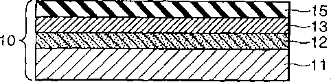
Figure 1A is to illustrate according to a preferred embodiment of the present invention to 1E, makes the profile of each step of SOI substrate.
In the step shown in Figure 1A, prepare a monocrystalline substrate 11, and for example use anode oxidation method, on the surface of monocrystalline substrate 11, form one deck porous silicon layer 12.In the step shown in Figure 1B,, on this porous silicon layer 12, form the non-porous monocrystalline silicon layer 13 of one deck by epitaxial growth.On this non-porous monocrystalline silicon layer 13, form insulating barrier (for example silicon dioxide layer) 15 again.With this technical process, form the 1st substrate 10.
In the step shown in Fig. 1 C, prepare one the 2nd substrate 20, and it closely contacted with the 1st substrate 10, with make insulating barrier 15 relative with the 2nd substrate 20 to.Then by means of anode linkage, pressurization, heating, or the method for its combination, make the 1st substrate 10 and the 2nd substrate 20 bondings.With this insulating barrier 15 and the 2nd substrate 20 firmly bonding get up and form bonded substrate lamination 50.As above said, can on non-porous polysilicon layer 13, form this insulating barrier 15.On the other hand, also can or be formed on non-porous polysilicon layer 13 and the 2nd substrate 20 on both, form this insulating barrier 15,, make the 1st closely to contact mutually with the 2nd substrate and obtain with regard to the situation shown in Fig. 1 C at the 2nd substrate 20.
In the step shown in Fig. 1 D, the substrate after porous silicon layer 12 places separate these two bondings.The 2nd substrate one side (10 "+20) has porous silicon layer 12 "/sandwich construction of polysilicon layer 13/ insulating barrier 15/ monocrystalline substrate 20.The 1st substrate one side (10 ') have on a kind of wherein monocrystalline substrate 11 form porous silicon layer 12 ' structure.
Removed residual porous silicon layer 12 ' after, if needed, can be with this polysilicon layer 12 ' complanation, as monocrystalline substrate 11, form one the 1st substrate (10) again to the substrate (10 ') after separating.
Separated after this bonded substrate lamination,, removed the lip-deep porous layer 12 of the 2nd substrate one side (10 "+20) selectively " in the step shown in Fig. 1 E.With such technical process, just can obtain to have the sandwich construction of amorphous silicon layer 13/ insulating barrier 15/ monocrystalline substrate 20, i.e. a kind of substrate of soi structure.
As for the 2nd substrate, for example, not only can use monocrystalline substrate, and can use dielectric substrate (for example, quartz substrate) or transparent substrates (for example, quartz substrate).
In above-mentioned process for making, for making things convenient for two substrates of bonding and, in this separated region, forming the porous silicon layer 12 that one deck has weak structure with its separation processes process (Fig. 1 D).Replace this porous silicon layer, for instance, can form one deck microporous layers.This microporous layers, for example, the method that ion can be injected a Semiconductor substrate forms.
To illustrate a kind ofly below, for example be suitable for the system of processing that the bonded substrate lamination separates processing in the technical process process of soi structure in above-mentioned manufacturing.
Fig. 2 shows system of processing illustrative configurations plane graph according to the preferred embodiment of the invention.A system of processing 3000, the precalculated position on supporting station 3200 (for example, being positioned at the center) has a undirected automatic control equipment 3150, as the connecting gear of bonded substrate lamination.Be used to handle or process the various process equipments of bonded substrate lamination, the power transmission shaft 3151 that is configured in undirected automatic control equipment 3150 separates equidistant position.More precisely, in the present embodiment, the power transmission shaft 3151 that loading machine 3080, centering equipment 3070, separation equipment 3020, tipping arrangement 3130, washing/drying equipment the 3120, the 3rd unloader the 3110, the 2nd unloader 3100 and the 1st unloader 3090 are configured in undirected automatic control equipment 3150 separates equidistant position.
First being processed is put into loading machine 3080 tops to the 1st box 3081 of depositing one or more bonded substrate laminations.Before processing, the 2nd box 3091 of a sky is put into the 1st unloader 3090 tops, the 3rd empty box 3101 is put into the 2nd unloader 3100 tops, and the 4th empty box 3111 is put into the 3rd unloader 3110 tops.
Undirected automatic control equipment 3150 has automatic operator 3152, in order to be installed and to keep a bonded substrate lamination.Automatically operator 3152 on horizontal plane around power transmission shaft 3151 rotations, move near or leave power transmission shaft 3151, thereby between each equipment, transmit the bonded substrate lamination.
The bonded substrate lamination that centering equipment 3070 receives from undirected automatic control equipment 3150 is carried out the processing (centering) in the centrally aligned precalculated position that makes the bonded substrate lamination, then this bonded substrate lamination is transferred to undirected automatic control equipment 3150.
In the embodiment shown in Figure 2, separation equipment 3020 sprays fluid (jet media), facing to this porous layer of bonded substrate lamination, at this porous layer place, the bonded substrate lamination is separated by means of this fluid.This separation equipment 3020 is placed in the cell, in order to avoid the following jet media that will illustrate (for example, water) scatters to peripheral part.This cell 3010 has a plate washer 3060, and the automatic operator 3152 of undirected automatic control equipment 3150 can enter/leave cell by this plate washer.This separation equipment has a nozzle 3040, in order to spray a branch of jet.The position of this nozzle 3040 is controlled by the automatic control equipment 3050 of quadrature.As for separation equipment 3020, also can adopt the separation equipment of other type, will introduce later on.
This tipping arrangement 3130 makes the last substrate rotation in two substrates after the separation, and (make after the separation substrate surface up) up to 180 °, turns over this substrate.This undirected automatic control equipment 3150 can have the function of substrate rotation up to 180 °, and substrate is turned over.In this case, also can save turning device 3130.
This washing/drying equipment 3120 cleans and the substrate of drying after separating.The also equipment that can adopt cleaning equipment and drying equipment to separate, and without washing/drying equipment 3120.
This system of processing 3000 according to the instruction that operating desk comes, is carried out the separation processing of bonded substrate lamination.
The course of processing of this system of processing will be described below.At first, (for example, the bonded substrate lamination 50 shown in Fig. 1 C) the 1st box 3081 manually or automatically is arranged to the precalculated position on the loading machine 3080 with depositing bonded substrate lamination to be processed.The 2nd box the 3091, the 3rd box 3101 and the 4th box 3111 with sky are arranged to respectively on the 1st unloader the 3090, the 2nd unloader 3100 and the unloader 3110.In the present embodiment, the 2nd box 3091 is in order to depositing down separate substrate, and the bonded substrate lamination (or the substrate after separating) that the 4th box 3111 is damaged when separating in order to deposit.The 1st box 3081 is settled on the loading machine 3080, makes the bonded substrate lamination that deposits in become level.The 2nd box the 3091, the 3rd box 3101 and the 4th box 3111 are placed in respectively on the 1st unloader the 3090, the 2nd unloader 3100 and the 3rd unloader 3110, make each substrate to deposit with level.
Fig. 3 is the flow chart of the course of processing of 3000 pairs of bonded substrate laminations of this system of processing of explanation.At step S101, undirected automatic control equipment 3150 is installed on the bonded substrate lamination of foot in the 1st box on this loading machine 3080, extracts this bonded substrate lamination out, and it is transferred to centering equipment 3070, keeps level simultaneously.At step S102, this centering equipment 3070 is felt relieved to this bonded substrate lamination, and it is transferred to undirected automatic control equipment 3150.
At step S103, open the plate washer 3060 of cell 3010, the bonded substrate lamination of aiming at from undirected automatic control equipment 3150, transfer to separation equipment 3020.This undirected automatic control equipment 3150 is preferably transferred to separation equipment 3020 to centering bonded substrate lamination later, supports this bonded substrate lamination with level from downside simultaneously.Can prevent that like this bonded substrate lamination from dropping down.Transferring to the bonded substrate lamination of this separation equipment 3020, is to have felt relieved.Therefore, when the automatic operator 3152 of this undirected automatic control equipment 3150 is shifted to the precalculated position, when this bonded substrate lamination was transferred to separation equipment 3020, this bonded substrate lamination just can be positioned in this separation equipment 3020.
At step S104, the plate washer 3060 of closed cells 3010, and separate processing with separation equipment 3020.More precisely, in the present embodiment, this separation equipment 3020, from the porous layer jetting stream of nozzle 3040 facing to the bonded substrate lamination, with level this bonded substrate lamination is rotated simultaneously,, make the bonded substrate lamination be divided into two substrates at the porous layer place by means of jet.
At step S105, open the plate washer 3060 of this cell 3010, reception is transferred to washing/drying equipment 3120 from the separate substrate of the bottom of separation equipment 3020 and this bonded substrate lamination.This undirected automatic control equipment 3150, preferably directly from separation equipment 3020 receive these substrates and substrate-transfer to washing/drying equipment 3120, simultaneously should this substrate of supporting from downside with level.So just can prevent that substrate from falling.
At step S106, this washing/drying equipment 3120 begins following separate substrate is cleaned and drying.
Handle parallel carrying out with washing/drying, at step S107, this undirected automatic control equipment 3150 receives from the last separate substrate of separation equipment 3020 and this substrate-transfer and arrives tipping arrangement 3130.This undirected automatic control equipment 3150 preferably receives the substrate from separation equipment 3020, supports this substrate with level from upper side simultaneously.With such configuration, very difficult power transmission shaft 3151 tops that adhere to this undirected automatic control equipment 3150 again of small pieces that adhere on the release surface are gone.
At step S108, this tipping arrangement 3130 overturns the substrate that receives 180 °.The course of processing lasts till that with this washing/drying equipment 3120 washing/drying is handled till the end of this time substrate.
At step S109, this undirected automatic control equipment 3150 receives substrates down from washing/drying equipment 3120, and substrate is deposited in the 2nd box 3091 on the 1st unloader 3090.This undirected automatic control equipment 3150 preferably receives the substrate from separation equipment 3020, and it is left in the 2nd box 3091, and should this substrate of supporting from downside with level.Can prevent that like this this substrate from falling.
At step S110, this undirected automatic control equipment 3150 receives from tipping arrangement 3130 and goes up substrate, and this substrate-transfer is arrived washing/drying equipment 3120.This undirected automatic control equipment 3150 preferably receives substrate and it is transferred to washing/drying equipment 3120, and supports this this substrate with level from downside.Can prevent that like this this substrate from falling.
At step S111, this washing/drying equipment 3120 cleans and dry upward substrate.At step S112, this undirected automatic control equipment 3150 receives from washing/drying equipment 3120 and goes up substrate, and this substrate is left in the 3rd box 3101 on the 2nd unloader 3100.This undirected automatic control equipment 3150 preferably receives the substrate from washing/drying equipment 3120, and it is left in the 3rd box 3101, and supports this substrate with level from downside.Can prevent that like this substrate from falling.
In the course of processing shown in Figure 3, at first clean and dry separate substrate down.On the contrary, also can at first clean and the dry separate substrate that goes up.In this case, the course of processing is then according to for example, and the order of step S101, S102, S103, S104, S107, S108, S110, S111, S112, S105, S106 and S109 carries out.
In this system of processing 3000, this undirected automatic control equipment 3150 according to the instruction of operating desk 3140 by operator input, leaves the damaged substrate of separation in the 4th box 3111 on the 3rd unloader 3110 in.Also can be equipped with the released state surveillance equipment and detect the separation damaged condition, rather than separate damaged condition according to operator's instruction identification.
The running of the system of processing 3000 that is used for a bonded substrate lamination has been described above.In this system of processing 3000, a plurality of bonded substrate laminations of processing also can walk abreast.
Fig. 4 shows the course of processing illustration that is used for a plurality of bonded substrate laminations of parallel processing.With reference to Fig. 4, so-called " centering " is by centering equipment 3070 processing of feeling relieved, " separation " processes separation by separation equipment 3020, and by tipping arrangement 3130 processing of overturning, " washing/drying " then carries out washing/drying by washing/drying equipment 3120 and handle " upset ".T1 is cycle with bonded substrate lamination of an apparatus processing (be two after the separation, promptly go up substrate and following substrate) to T6.In addition, " #1 " arrives " #6 " expression bonded substrate lamination number, and " #1 " of subscripting " a " arrive the last substrate after " #6 " expression separates, the last substrate after " #1 " of subscripting " b " arrives " #6 " and then represent separation.
In the example shown in Figure 4, during period T 1, only carry out the centering of bonded substrate lamination # 1 and handle.During period T 2, parallel carry out the separation processing of bonded substrate lamination # 1 and the centering of bonded substrate lamination # 2 is handled.
During period T 3, the last substrate # 1a upset that the centering of the parallel separation processing of carrying out the bonded substrate lamination, bonded substrate lamination is handled, obtained by separating bonded substrate lamination # 1 is handled and two substrate # 1a obtaining by separating the bonded substrate lamination and the washing/drying processing of #1b.In example shown in Figure 4, first half period of period T 3, the upset of last substrate # 1a is handled and the washing/drying of following substrate # 1b is handled, and feels relieved processing and separates processing so that walk abreast.In second half period of period T 3, the washing/drying of the last substrate # 1a after overturning is handled, and feels relieved processing and separates processing so that walk abreast.
Fig. 5 shows by this undirected automatic control equipment transmission bonded substrate lamination or the process of the substrate after separating and the processes implementation of this equipment.With reference to Fig. 5, horizontal line is represented to be processed by equipment, and oblique line is then represented to carry out the process that substrate transmits by this undirected automatic control equipment 3150.
System of processing 3000 according to present embodiment, because have only a undirected automatic control equipment 3150 as undirected automatic control equipment, in order to the substrate that transmits the bonded substrate lamination or separated, thus can not transmit a plurality of bonded substrate laminations simultaneously or separate after substrate.
But this undirected automatic control equipment 3150 is used for the required time of transport process, usually than the time much shorter that separates processing with this separation equipment 3020.So, automatic control equipment be enough to transmit the bonded substrate lamination or separate after substrate.During substrate after needs transmit a plurality of bonded substrate laminations simultaneously or separate, for example when only with an automatic control equipment treatment effeciency reduction, just can use many automatic control equipments (for example, undirected automatic control equipment).
As mentioned above, according to this system of processing, a plurality of bonded substrate laminations of processing that can walk abreast, the result is the productivity ratio height.
According to present embodiment, owing to, therefore can adopt the automatic control equipment (for example, undirected automatic control equipment) of relative simple structure as connecting gear with the substrate after level transmission bonded substrate lamination or the separation.
According to present embodiment, individual device is configured in precalculated position (power transmission shaft of undirected automatic control equipment) roughly equidistant position separately.When making undirected automatic control equipment 3150, on horizontal plane around power transmission shaft 3151 rotations and move near or when leaving this power transmission shaft 3151, just can be at the substrate after transmitting bonded substrate lamination or separation between each equipment.So, for instance, do not need to be equipped with the transmission mechanism that is used on horizontal plane, moving undirected automatic control equipment 3150.
The configuration of this separation equipment 3020 will be described below.
[the 1st configuration of separation equipment]
The jetting method of water is answered in the 1st configuration of this separation equipment.Generally, the jetting method of water sprays at a high speed, High-Pressure Water, for example is with cutting or processing ceramic, metal, concrete, resin, rubber or timber, root out the coverlay on surface, district, or clean surface is purpose (" water jet ", Vol.1, No.1, page 4 (1984)).
This separation equipment makes the fluid jet flow be ejected into porous layer (separating layer) as the weak structure of bonded substrate lamination, and therefore optionally broken this porous layer makes the substrate lamination separate at this porous layer place.In this specification this jet flow is called " jet ".The fluid that forms jet is called " jet media ".As jet media, can make water, organic solvent such as ethanol, acid such as hydrofluoric acid or nitric acid, highly basic such as potassium hydroxide, gas such as air, nitrogen, carbonic acid gas rare gas, or corrosive gas, or plasma and so on.
When this separation equipment is applied to make semiconductor device or separation, for example, the bonded substrate lamination, preferably, foreign metal or the minimum pure water of particle, as the fluid that forms jet.
The condition of this jet injection for example can be decided by the type of separated region (for example, porous layer) or the shape of bonded substrate lamination side.With regard to the jet injection condition, for example, put on the distance between speed, nozzle width or diameter (this diameter is the same with jet diameter haply), nozzle form, this nozzle and the separated region of pressure, jet scanning of jet media and the flow of jet, all can be used as important parameter.
According to the separation method that uses the water jet method, the bonded substrate lamination can be divided into two substrates and can not damage this bonded substrate lamination.
This separation equipment keeps a sample, resembles bonded substrate lamination and so on, and is horizontally disposed with the surface of this sample haply, under such state, locates to separate this sample at weak structure (for example, porous layer).When the surface with its horizontal setting kept sample, for example: (1) can prevent that sample from falling; (2) can easily keep sample; (3) be easy to transmit sample; (4) can between separation equipment and miscellaneous equipment, transmit sample effectively; And (5) can reduce the design area (area occupied) of separation equipment, because can be at the vertical direction layout structure.
Fig. 6 shows the schematic diagram of the 1st configuration of separation equipment.This separation equipment 1000 has a pair of substrate maintaining part 270 and 1010.
Last substrate maintaining part 270 is coupled to an end of rotating shaft 140.The other end of rotation axis 140 is passed through shaft coupling 130, be coupled in the rotating shaft of motor 110.Motor 110 and rotation axis 140 can not pass through shaft coupling 130 couplings, but by for example belt or other mechanism's coupling.This motor 110 is fixed to and is fixed on 170 the supporting member 120 of appearing on the stage.This motor can be controlled by the control assembly (not shown).
This substrate maintaining part 1010 with Bernoulli disk 1013 is coupled to an end of lift shaft 1020.The gas introducing portion 1011 of Bernoulli disk 1013 is coupled on the pressure piping 1021 in the lift shaft 1020.Pressure piping 1021 is connected to the external pressure pipeline via sealing ring 1022.This external pressure pipeline has the electromagnetically operated valve (not shown).As needs, this electromagnetically operated valve carries out ON/OFF control (not shown) by control assembly.
The other end of this lift shaft 1020 is by the piston rod coupling of shaft coupling 330 with cylinder 320.This lift shaft 1020 via subtend/guiding member rotating 1030,240 support by leaving office.
This nozzle 3040 is by automatic control equipment 3050 controls of above-mentioned quadrature.A plate washer 3030 inserts between this nozzle 3040 and substrate maintaining part 270 and 1010.This plate washer 3030 carries out opening/closing by motor 250.When having opened plate washer 3030, just under such state, eject jet from nozzle 3040, jet is injected on the bonded substrate lamination 50.When closing plate washer 3030, just can be injected on the bonded substrate lamination by jet barrier.
The separation course of processing with this separation equipment 1000 will be described below.This cylinder 320 retracts piston rod, forms appropriate gap in substrate maintaining part 270 and 1010 of substrate maintaining parts.Under such state, flatly from downside, be inserted into precalculated position between this substrate maintaining part 270 and the substrate maintaining part 1010 with these bonded substrate laminations 50 of automatic operator 3152 supporting of undirected automatic control equipment 3150, and be placed in this substrate maintaining part 1010 tops.
Fig. 7 schematically shows the outline drawing of substrate maintaining part 270 and 1010.This substrate maintaining part 270 and 1010 at its outer peripheral portion, has a plurality of guide 270a and 1010a respectively, can prevent that in separation process the bonded substrate lamination from producing offset or stretch out from the substrate maintaining part.
For enabling automatic operator 3152 with undirected automatic control equipment 3150, the bonded substrate lamination is sent to substrate maintaining part 270 or substrate maintaining part 1010, thereby from downside supporting bonded substrate lamination 50 or each substrate lower surface after separating that is installed (upper surface is the surface after separating), each substrate that allows this automatic operator 3152 to receive from substrate maintaining part 270 and 1010, for example, preferably dispose a plurality of guide 270a and 1010a, make automatic operator 3152 can enter/leave with proper spacing.For instance, arrange three guide 270a and three guide 1010a with the interval of hexagonal angle.
Secondly, during these cylinder 320 elongation piston rods, substrate maintaining part 1010 is moved up up to the upper surface of bonded substrate lamination 50 and the support of last substrate maintaining part 270, and have predetermined distance therebetween.After the electromagnetically operated valve of external pressure pipeline is opened,, block bonded substrate lamination 50 from the rapid gas jet in Bernoulli disk 1013 centers of substrate maintaining part 1010.
In the plate washer 3030 that keeps closing, start the pump (not shown) with nozzle 3040, high-pressure spray medium (for example, water) is fed to nozzle 3040.High-pressure spray sprays from this nozzle 3040.When jet is stablized, just open plate washer 3030.By the jet of nozzle 3040 ejections, inject the porous layer of bonded substrate lamination 50 continuously, begin to separate this bonded substrate lamination 50.
When finishing 50 separation of bonded substrate lamination, just close this plate washer 3030, and the pump that connects with nozzle 3040 is stopped, stopping jet and inject bonded substrate lamination 50.That is stop motor 110 operation.
In the time of the Bernoulli disk 1013 that keeps starting substrate maintaining part 1010, just drive the vacuum chuck mechanism of this substrate maintaining part 270.Last separate substrate is held by substrate maintaining part 270 vacuum.Simultaneously, following separate substrate is installed by the Bernoulli disk of 10 substrate maintaining parts 1010.
The automatic operator 3152 of undirected automatic control equipment 3150 is inserted between the Bernoulli disk 1013 of substrate and substrate maintaining part 1010.This automatic operator 3152 substrate that is installed.After, remove the Bernoulli disk 1013 of substrate maintaining part 1010 and inhale card, and with this substrate from substrate maintaining part 1010, send automatic operator 3152 to.
Unit is inserted between substrate maintaining part 270 and the substrate to the automatic operator 3152 of automatic control equipment 3150.This automatic operator 3152 blocks substrate.After this, remove the suction card of substrate maintaining part 270, and with this substrate from substrate maintaining part 270, send automatic operator 3152 to.
After this bonded substrate lamination 50 is divided into two substrates, jet media will be present between two substrates.When jet media was liquid (for example, water), surface tension was quite big.Thereby, can separate two substrates with little power, jet preferably is fed in two gaps between the substrate by nozzle 3040.Therefore, after having separated two substrates, stop jet from nozzle 3040.Replace, also can independently be equipped with the mechanism that is used to separate two substrates with jetting stream.
[the 2nd configuration of separation equipment]
This configuration also relates to the separation equipment that separates the bonded substrate lamination by means of jet as the 1st configuration.
Fig. 8 shows the schematic diagram of the 2nd configuration of separation equipment.Fig. 9 shows the part figure of this separation equipment shown in Figure 8.This separation equipment 1900 has a pair of substrate maintaining part 1909 and 1901.This substrate maintaining part 1909 and 1901 in the mode that it is clipped in the middle, from two sides up and down, flatly keeps bonded substrate lamination 50.Jet injects the porous layer of bonded substrate lamination 50 from nozzle 3040 ejection, thereby bonded substrate lamination 50 is divided into two substrates at the porous layer place.
Following substrate maintaining part 1901 has one and transmits support 1903, and it forms a space between bonded substrate lamination 50 and following substrate maintaining part 1901, so that the automatic operator 3152 of undirected automatic control equipment 3150 can be inserted in this space.This support 1903 has the be installed aspirating hole 1902 of this bonded substrate lamination 50 of a vacuum.This time substrate maintaining part 1901 around support 1903, has a skew protector 1911.For example the skew protector 1911 that forms with rubber or resin can prevent bonded substrate lamination 50 moving at in-plane.Utilize such skew protector 1911, just can keep bonded substrate lamination 50 with little pressure or suction.
This time substrate maintaining part 1901 is coupled to an end of rotation axis 1904.1904 of this rotation axiss pass through bearing 1906 by supporting station 1920 supportings.This bearing 1906, its top have a seal 1905, are formed at opening portion in the supporting station 1920 in order to sealing, so that run through rotation axis 1904.A vacuum line 1907 runs through this rotating shaft 1904.Vacuum line 1907 is connected on the aspirating hole 1902 of substrate maintaining part 1901.This vacuum line 1907 also passes sealing ring 1908 and is connected on the external vacuum pipeline.This rotation axis 1904 is connected on the ROTATING SOURCE (not shown), is applied rotatory force and is rotated by ROTATING SOURCE.
Substrate maintaining part 1909 is assemblied in the top of substrate maintaining part 1901.This substrate maintaining part 1909 is connected to the power transmission shaft 1910 of transmission mechanism 1930, does vertical moving by means of transmission mechanism 1930.This power transmission shaft 1910 is axially supported rotatably by transmission mechanism 1930.
Last substrate maintaining part 1909 has the supporting member 1912 of flange, and it forms the space between bonded substrate lamination 50 and substrate maintaining part 1909, makes the automatic operator 3152 of this undirected automatic control equipment 3150 can insert in this gap.Supporting member 1912 has the be installed aspirating hole 1914 of bonded substrate lamination 50 of vacuum.This substrate maintaining part 1909 has a skew protector 1913 around supporting member 1912.This is offset protector 1913, is for example formed by rubber or resin, can prevent that bonded substrate lamination 50 from moving at in-plane.Such supporting member 1912 is arranged, just can keep bonded substrate lamination 50 with little pressure or suction.
This nozzle 3040 is controlled by the automatic control equipment 3050 of above-mentioned quadrature.Plate washer 3030 inserts between nozzle 3040 and the substrate maintaining part 1901.These plate washer 3030 usefulness motor (not shown) opening/closings.When this plate washer 3030 was opened, under this state, jet just from nozzle 3040 ejections, can be injected into this jet on the bonded substrate lamination 50.When plate washer 3030 is closed, just can interrupts jet and inject bonded substrate lamination 50.
Below the process of separating processing by means of separation equipment 1900 will be described.At first,, substrate maintaining part 1909 is moved up, between substrate maintaining part 1909 and substrate maintaining part 1901, form suitable space by means of transmission mechanism 1930.Under these circumstances, flatly support this bonded substrate lamination 50 by the automatic operator 3152 of undirected automatic control equipment 3150 and be placed in support 1903 tops of substrate maintaining part 1901 from downside.Move down substrate maintaining part 1909 by transmission mechanism 1930, make this substrate maintaining part 1909 para-linkage substrate laminations 50 pressurizations.This substrate maintaining part 1909 and 1901 from two sides to 50 pressurizations of this bonded substrate lamination and with its maintenance.
The vacuum that drives substrate maintaining part 1901 and the 1909 mechanism's bonded substrate lamination 50 that is installed that is installed.Start the ROTATING SOURCE (not shown), transmit rotatory force and give rotation axis 1904.This rotation axis 1904, substrate maintaining part 1901, bonded substrate lamination 50 and substrate maintaining part 1909 are rotated with regard to integral body.
Keep plate washer 3030 closed period, starting the compression pump (not shown) that is connected to nozzle 3040, giving nozzle 3040 high-pressure spray medium (for example, water).High-pressure spray just ejects from this nozzle 3040.When jet is stablized, open nozzle 3040.Jet from nozzle 3040 ejections injects on the porous layer of bonded substrate lamination 50, continuously so begin to separate this bonded substrate lamination 50.
When the separation of bonded substrate lamination 50 finishes, shut-off nozzle 3040, and stop the operation of the pump that is connected with nozzle 3040, jet injection bonded substrate lamination 50 is stopped.Axle 1904 the transmission that also just stops operating is stopped the rotation of separate substrate.
The vacuum that restarts substrate maintaining part 1901 and 1909 mechanism that is installed.Be installed by means of substrate maintaining part 1909 and go up separate substrate.Simultaneously, by means of substrate maintaining part 1901 separate substrate that is installed down.By transmission mechanism 1930 substrate maintaining part 1909 is moved up.Two substrates that separated have been divided each other come.
The automatic operator 3152 of undirected automatic control equipment 3150 is inserted between this substrate maintaining part 1901 and the substrate.Make automatic operator 3152 this substrate that is installed.Then, the vacuum of removing this substrate maintaining part 1901 being installed of mechanism that be installed, and this substrate passed to automatic operator 3152 from substrate maintaining part 1901.
The automatic operator 3152 of just undirected automatic control equipment 3150 is inserted between this substrate maintaining part 1909 and the substrate.This automatic operator 3152 this substrate that is installed.Then, the vacuum of removing this substrate maintaining part 1909 being installed of mechanism that be installed, and this substrate passed to automatic operator 3152 from substrate maintaining part 1909.
After this bonded substrate lamination 50 is divided into two substrates, exist jet media between two substrates.When this jet media was liquid (for example, water), its surface tension was quite big.Therefore, in order to separate two substrates, preferably jet is fed in the gap between two substrates by nozzle 3040 with less power.Under these circumstances, two separated jets that just stop afterwards by nozzle 3040 of substrates.Replace, also can be equipped with the jet that is used for two substrates of injection of separation independently.
[the 3rd configuration of separation equipment]
Figure 10 and 11 shows the constructed profile of the 3rd configuration of separation equipment.Figure 10 shows the state that substrate support spare wherein is opened.Figure 11 shows the state that substrate support spare wherein is closed.
This substrate support spare 4001 and 4004 has seal (for example, the O-sealing ring) 4002 and 4005 respectively, to guarantee the air-tightness between sealing part and the bonded substrate lamination 50.Substrate support spare 4004 has a seal 4008, to guarantee the air-tightness between the substrate support spare 4001 and 4004.
In this separation equipment 4000,, pin substrate support spares 4001 with latching device 4007 bonded substrate lamination 50 being sandwiched when neutralizing assurance substrate support spare 4001 and 4004 in two-side supporting.
This substrate support spare 4004 has an injection member 4006, in order to fluid is injected closed space 4020.This injection member 4006 is connected to for example compression pump of pressure source 4011.The fluid (for example, water) of 4020 fillings of this closed space to supply with by pressure source 4011.
This substrate support spare 4001 and/or 4004 can have exhaust outlet, injects the bubble that closed space 4020 produces to remove with fluid, and a valve, when the fluid in closed space 4020 is exerted pressure, in order to close exhaust outlet.
This pressure source 4011 is exerted pressure to fluid, with fluid-filled space 4020 that should closure.This pressure source 4011 preferably has adjustment to mechanism that fluid is exerted pressure.Mechanism with such exerts pressure to fluid, preferably adjusts to high pressure in early days what bonded substrate lamination 50 separated, then gradually or segmentation descend.For example, at the commitment that separates, pressure is for example adjusted to 20kg/cm
2, drop to the separation final stage later on gradually, for example, 1kg/cm
2
This time substrate support spare 4004 is to support with supporting station 4006.This supporting station 4006 has an air vent hole 4030, and the lower surface of bonded substrate lamination 50 is communicated with outside atmosphere.The lower surface of bonded substrate lamination 50 is kept under atmospheric pressure.This supporting station 4006 has a cylinder 4010 near core.Supporting part 4009 is linked on the piston rod of cylinder 4010.When reception/transmission bonded substrate lamination or the substrate after separating, from/when giving the automatic operator 3152 of undirected automatic control equipment 3150, just promote supporting part 4009 upwards.With such supporting part 4009, will form the gap of accepting automatic operator 3152 with the bonded substrate lamination or between the substrate after separating at following substrate support spare 4004.
The process of separating processing bonded substrate lamination 50 by means of this separation equipment 4000 will be described below.For example, under atmospheric pressure separate processing.
At first, open these substrate support spares 4001 and open by latching device 4007, as shown in figure 10, supporting part 4009 moves up.Automatic operator 3152 with undirected automatic control equipment 3150 is placed in bonded substrate lamination 50 on the substrate support spare 4004.
As shown in figure 11, move down supporting part 4009, and seal and pin substrate support spare 4001 with latching device 4007.Under this state,, form closed space 4020 round bonded substrate lamination 50 marginal portions of having exposed porous layer 50c.
By means of pressure source 4011, fluid is injected this closed space 4020.Exert pressure for the fluid in the closed space 4020 by means of this pressure source 4011.Be applied on the porous layer 50c that has exposed bonded substrate lamination 50 edges stablizing this constant fluid pressure haply.
Along with applied pressure destroys the porous layer 50c that exposes bonded substrate lamination 50 edges, just begun to separate.When this fluid was injected in the part of having broken, breaking of this porous layer 50c just advanced.The propelling of breaking along with porous layer 50c is injected into enough fluids in this bonded substrate lamination 50.At that time, because fluid acts on bonded substrate lamination 50 pressure inside and acts on difference between the pressure of non-closed space (that is, not being closed space),, substrate 50a is separated with 50b so there is a separating force to act on the bonded substrate lamination 50.Separate and just go on this separating force.
When separating end, controlled pressure source 4011 for example is under the atmospheric pressure closed space 4020.Then, unclamp latching device 4007.Open this substrate support spare 4001, the supporting part 4009 that moves up, and between following substrate support spare 4004 and the bonded substrate lamination that has separated, form suitable space.Automatic operator 3152 with undirected automatic control equipment 3150 takes out upward substrate 50a again, takes out substrate 50b down then.
In this case, after will going up substrate 50a upset by tipping arrangement 3130, clean and drying with washing/drying equipment 3120, and leave in the 3rd box 3101, perhaps after should going up substrate 50a and delivering to tipping arrangement 3130, substrate 50b down is sent to washing/drying equipment 3120.
[the 4th configuration of separation equipment]
Figure 12 shows the schematic diagram of the 4th configuration of this separation equipment.This separation equipment 5000 is added to pressure on the whole bonded substrate lamination 50, and bonded substrate lamination 50 is separated.
This separation equipment 5000 has an airtight container 5001, in order to deposit bonded substrate lamination 50 and to form closed space, and has a sealing flange 1202, in order to the opening/closing opening portion, by this opening portion, the automatic operator 3152 of undirected automatic control equipment 3150 can enter/leave this closed containers 5001.This closed containers 5001 has a sample supporting member 5011, from downside supporting bonded substrate lamination 50.
This separation equipment 5000 has an inlet 5008, and fluid is supplied with this closed space.This inlet 5008 is connected with pump 5010 via valve 5009.This separation equipment 5000 also has a floss hole 5006, in order to the fluid of 5001 li of discharging closed containers.This floss hole 5006 is connected with exhaust-control valve 5007.
This separation equipment 5000 preferably has a vibration source 5004, and the vibrational energy that resembles ultrasonic wave and so on is applied on the bonded substrate lamination 50.With such vibration source 5004, can carry out the separation processing of two steps.In the phase I, pressure is applied to the seal cavity that is formed by closed container 5001, destroy the hole wall in the porous layer, as mentioned above.In second stage, destroy remaining hole wall with vibrational energy, thereby separate this bonded substrate lamination 50 fully at the porous layer place.
The separation course of processing by means of this separation equipment 5000 will be described below.At first, open sealing flange 5002, be delivered to the bonded substrate lamination in the closed containers 5001 and be placed on the sample supporting member 5011 with the automatic operator 3152 of undirected automatic control equipment 3150.
Close sealing flange 5002.Start pump 5010, open valve 5009, fluid is injected airtight space.The internal pressure of confined space is fixed to predetermined pressure (first separates the course of processing begins).As fluid, can using gases such as air, or liquid such as water and so on.As fluid, also can use energy selective etch aperture to contain the etching gas or the etchant of layer.In this case, processing can be separated fully, and after separating, the hole wall quantity that may stay can be reduced.
In this case, this course of processing will be waited for for example scheduled time.Make bonded substrate lamination 50, thoroughly separation or maximum hole wall break at the porous layer place.Then, stop this pump 5010 runnings, and Shuttoff Valve 5009.Open exhaust-control valve 5007 again,, discharge the fluid in the seal cavity, thereby make the pressure in the seal cavity get back to atmospheric pressure (first separation process end) through floss hole 5006.When using the fluid that natural environment is harmful to, the fluid of discharging by floss hole 5006 will reclaim and suitably handle.
Then start vibration source 5004, vibrational energy is added on the bonded substrate lamination 50 in the airtight container.Use this technical process, make uncracked hole wall fragmentation, and this bonded substrate lamination 50 is thoroughly separated (second separation process).The second separation processing can separate with first processes parallel carrying out.
When a kind of liquid when this fluid, as needs, can discharge fluid in the seal cavity by opening valve 5007.Again sealing flange 5002 is opened.Go up substrate with automatic operator 3152 taking-ups of this undirected automatic control equipment 3150 and then take out down substrate.Under these circumstances, make on this after substrate upset by means of tipping arrangement 3130, clean and drying with washing/drying equipment 3120, and leave in the 3rd box 3101, perhaps after should going up substrate and delivering to tipping arrangement 3130, substrate down is sent to washing/drying equipment 3120.
[other structure of the automatic operator of undirected automatic control equipment]
Other structure of automatic operator in this undirected automatic control equipment then will be described.Figure 13 A and 13B show other structure chart of the automatic operator of this undirected automatic control equipment.Figure 13 A is a plane graph, and Figure 13 B is the profile of A-A ' along the line among Figure 13 A.Automatic operator shown in Figure 13 A and the 13B has U-shape main body 9004 and retaining part 9001 to 9003, be used to keep a bonded substrate lamination or separate after the marginal portion of substrate.Retaining part 9001 to 9003 is preferably for example formed by PTFE.
Automatic operator with this structure is only with the bonded substrate lamination or the contact of the end of the substrate after separating.Therefore, the substrate little impaired after bonded substrate lamination or the separation is hindered.
Automatic operator with this structure is only with the bonded substrate lamination or the contact of the end of the substrate after separating.Therefore, do not depend on that the surface of whether separating is towards upper side or downside, even during the substrate after downside keep to separate, this bonded substrate lamination or separate after substrate also little impaired hinder.
Automatic operator with this structure keeps a bonded substrate lamination or separates back substrate, adjust this bonded substrate lamination simultaneously or separate after substrate, prevent from in-plane, to move.For this cause, thus can prevent the bonded substrate lamination or separate after substrate drop down.
Automatic operator with this structure on one or all retaining part 9001 to 9003, can have the mechanism of being installed.Under these circumstances, can prevent more effectively that the substrate after bonded substrate lamination or the separation from falling down.In addition, for example, also can come support substrate from upper side.
Automatic operator with this structure can have the mechanism of rotating main body 9004, the substrate after it is installed and separates, and this substrate that overturns is up to 180 °.
According to the present invention, for example, owing to can change the running position by pivoting turntable, so can be to carry out a series of processing runnings at a high speed.
The invention is not restricted to the embodiments described, and also may make variations and modifications within the spirit and scope of the present invention.Therefore, inform open scope of the present invention, make following claims.
Claims (21)
1, a kind of system of processing that is used to process sheet sample comprises:
Connecting gear has retaining part, is used for approximate horizontal ground and keeps a sheet sample, and described connecting gear transmits the sheet sample that is kept by described maintaining part branch; And
Many process equipments are configured in the driving shaft of described connecting gear and are separated by on roughly equidistant position,
Wherein, when receiving/passing on sheet sample with the state of approximate horizontal between each in described many process equipments and the retaining part of described connecting gear, described connecting gear make described retaining part roughly on a horizontal plane around drive shaft turns and move to described retaining part close or leave this driving shaft, thereby between described many process equipments, transmit sample, and
Described many process equipments comprise:
Separation equipment is separated into two sheet samples with described sheet sample during the sheet sample that is used for keeping to be separated on approximate horizontal ground; And
Tipping arrangement is used for adopting described separation equipment by the top sheet sample that separates two sheet samples that obtain 180 degree that sway.
2, according to the described system of claim 1, wherein this sheet sample to be processed has a separating layer, and described separation equipment separates this sheet sample at this separating layer place.
3, according to the described system of claim 1, wherein said separation equipment is towards separating layer injection stream body fluid flow, thereby at this separating layer place this sheet sample separated.
4, according to the described system of claim 1, when wherein said separation equipment rotates this sheet sample in horizontal plane towards separating layer injection stream body fluid flow, thereby this sheet sample is separated.
5, according to the described system of claim 3, wherein said separation equipment is to keeping with downside and be clipped in central sheet sample separating from upper side.
6, according to the described system of claim 3, wherein said separation equipment comprises a sharp dish of the uncle slave as maintaining body, is used to keep this sheet sample.
7, according to the described system of claim 2, wherein said separation equipment applies changeless basically fluid pressure at least a portion of separating layer, so that separate this sheet sample at this separating layer place.
8, according to the described system of claim 2, wherein said separation equipment has the container of a sealing, deposits this sheet sample in this closed container, and the internal pressure of this closed container is set at high pressure, thereby at the separating layer place this sheet sample is separated.
9, according to the described system of claim 1, wherein said many process equipments comprise the equipment of centering, and are used for before this sheet sample is transferred to described separation equipment this sheet sample being centered.
10, according to each described system in the claim 2 to 9, wherein said many process equipments comprise cleaning equipment, to clean by adopting described separation equipment to separate the part of the sheet sample that obtains.
11, according to the described system of claim 1, also comprise cleaning equipment, be used for cleaning the sheet sample that obtains by described separation equipment separation in level.
12, according to the described system of claim 1, wherein said many process equipments comprise washing/drying equipment, are used to clean with dry separated and the sheet sample that obtains by described separation equipment.
13, according to the described system of claim 12, wherein said washing/drying equipment cleans in level with dry and is separated and the sheet sample that obtains by described separation equipment.
14, according to the described system of claim 1, the processing of wherein said many process equipments running is an executed in parallel.
15, according to the described system of claim 1, wherein said connecting gear comprises undirected automatic control equipment.
16, according to the described system of claim 2, wherein this separating layer is the layer with weak structure.
17, according to the described system of claim 16, wherein this layer with weak structure is a porous layer.
18, according to the described system of claim 16, wherein this layer with weak structure is a micro-cavity layer.
19, according to the described system of claim 1, wherein this sheet sample to be processed is a Semiconductor substrate.
20, according to the described system of claim 1, wherein this sheet sample to be processed is by bonding the 1st substrate and the 2nd substrate and form, and has the layer that one deck has weak structure, as separating layer.
21, according to the described system of claim 1, wherein this sheet sample to be processed is by forming a porous layer on the 1st semiconductor substrate surface, form a non-porous layer on this porous layer, and with the 2nd substrate bonding to this non-porous layer and form.
Applications Claiming Priority (2)
| Application Number | Priority Date | Filing Date | Title |
|---|---|---|---|
| JP316575/1998 | 1998-11-06 | ||
| JP31657598A JP4343295B2 (en) | 1998-11-06 | 1998-11-06 | Sample processing system |
Publications (2)
| Publication Number | Publication Date |
|---|---|
| CN1258091A CN1258091A (en) | 2000-06-28 |
| CN1160761C true CN1160761C (en) | 2004-08-04 |
Family
ID=18078631
Family Applications (1)
| Application Number | Title | Priority Date | Filing Date |
|---|---|---|---|
| CNB991234332A Expired - Fee Related CN1160761C (en) | 1998-11-06 | 1999-11-05 | Sample processing system |
Country Status (5)
| Country | Link |
|---|---|
| EP (1) | EP0999578A3 (en) |
| JP (1) | JP4343295B2 (en) |
| KR (1) | KR100444262B1 (en) |
| CN (1) | CN1160761C (en) |
| TW (1) | TW459299B (en) |
Families Citing this family (15)
| Publication number | Priority date | Publication date | Assignee | Title |
|---|---|---|---|---|
| EP0989593A3 (en) * | 1998-09-25 | 2002-01-02 | Canon Kabushiki Kaisha | Substrate separating apparatus and method, and substrate manufacturing method |
| TW484184B (en) | 1998-11-06 | 2002-04-21 | Canon Kk | Sample separating apparatus and method, and substrate manufacturing method |
| US6672358B2 (en) | 1998-11-06 | 2004-01-06 | Canon Kabushiki Kaisha | Sample processing system |
| JP2000150836A (en) | 1998-11-06 | 2000-05-30 | Canon Inc | Processing system for sample |
| DE10108369A1 (en) * | 2001-02-21 | 2002-08-29 | B L E Lab Equipment Gmbh | Method and device for detaching a semiconductor wafer from a carrier |
| JP2002353081A (en) | 2001-05-25 | 2002-12-06 | Canon Inc | Device and method for separating plate member |
| JP2002353423A (en) | 2001-05-25 | 2002-12-06 | Canon Inc | Separation device and processing method of plate member |
| JP4740414B2 (en) | 2007-04-24 | 2011-08-03 | 東京エレクトロン株式会社 | Substrate transfer device |
| US8443863B2 (en) * | 2008-10-23 | 2013-05-21 | Corning Incorporated | High temperature sheet handling system and methods |
| JP2011047515A (en) * | 2009-07-28 | 2011-03-10 | Canon Anelva Corp | Driving device and vacuum processing apparatus |
| JP2012069906A (en) * | 2010-08-23 | 2012-04-05 | Tokyo Electron Ltd | Joining device, joining method, program, and computer storage medium |
| JP5374462B2 (en) * | 2010-08-23 | 2013-12-25 | 東京エレクトロン株式会社 | Peeling system, peeling method, program, and computer storage medium |
| JP6404828B2 (en) * | 2013-11-25 | 2018-10-17 | リソテック ジャパン株式会社 | Processing chamber having small rotating arm and small manufacturing apparatus |
| JP6612648B2 (en) * | 2016-02-17 | 2019-11-27 | 東京応化工業株式会社 | Support body separating apparatus and support body separating method |
| US20190206704A1 (en) * | 2016-08-09 | 2019-07-04 | Kondoh Industries, Ltd. | Apparatus for Manufacturing Semiconductors |
Family Cites Families (11)
| Publication number | Priority date | Publication date | Assignee | Title |
|---|---|---|---|---|
| US5292393A (en) * | 1986-12-19 | 1994-03-08 | Applied Materials, Inc. | Multichamber integrated process system |
| JPH06268051A (en) * | 1993-03-10 | 1994-09-22 | Mitsubishi Electric Corp | Wafer stripper |
| US5934856A (en) * | 1994-05-23 | 1999-08-10 | Tokyo Electron Limited | Multi-chamber treatment system |
| JP3250722B2 (en) * | 1995-12-12 | 2002-01-28 | キヤノン株式会社 | Method and apparatus for manufacturing SOI substrate |
| US5928389A (en) * | 1996-10-21 | 1999-07-27 | Applied Materials, Inc. | Method and apparatus for priority based scheduling of wafer processing within a multiple chamber semiconductor wafer processing tool |
| SG55413A1 (en) * | 1996-11-15 | 1998-12-21 | Method Of Manufacturing Semico | Method of manufacturing semiconductor article |
| US5855681A (en) * | 1996-11-18 | 1999-01-05 | Applied Materials, Inc. | Ultra high throughput wafer vacuum processing system |
| US6382292B1 (en) * | 1997-03-27 | 2002-05-07 | Canon Kabushiki Kaisha | Method and apparatus for separating composite member using fluid |
| JPH115064A (en) * | 1997-06-16 | 1999-01-12 | Canon Inc | Separation device for sample and method thereof and production of board |
| GB2343550A (en) * | 1997-07-29 | 2000-05-10 | Silicon Genesis Corp | Cluster tool method and apparatus using plasma immersion ion implantation |
| KR19990049122A (en) * | 1997-12-11 | 1999-07-05 | 오상수 | Shock Absorber |
-
1998
- 1998-11-06 JP JP31657598A patent/JP4343295B2/en not_active Expired - Fee Related
-
1999
- 1999-11-03 TW TW088119172A patent/TW459299B/en not_active IP Right Cessation
- 1999-11-04 EP EP99308785A patent/EP0999578A3/en not_active Withdrawn
- 1999-11-05 CN CNB991234332A patent/CN1160761C/en not_active Expired - Fee Related
- 1999-11-06 KR KR10-1999-0049121A patent/KR100444262B1/en not_active IP Right Cessation
Also Published As
| Publication number | Publication date |
|---|---|
| CN1258091A (en) | 2000-06-28 |
| KR20000035284A (en) | 2000-06-26 |
| JP2000150610A (en) | 2000-05-30 |
| KR100444262B1 (en) | 2004-08-11 |
| EP0999578A2 (en) | 2000-05-10 |
| EP0999578A3 (en) | 2005-04-13 |
| JP4343295B2 (en) | 2009-10-14 |
| TW459299B (en) | 2001-10-11 |
Similar Documents
| Publication | Publication Date | Title |
|---|---|---|
| CN1160761C (en) | Sample processing system | |
| CN1205651C (en) | Cleaning device and cleaning method | |
| CN1175498C (en) | Composite member, its separation method, and preparation method of semiconductor substrate by utilization thereof | |
| US20050236114A1 (en) | Sample processing system | |
| US6527031B1 (en) | Sample separating apparatus and method, and substrate manufacturing method | |
| CN1127753C (en) | Sample processing system | |
| CN1264920A (en) | Separator, separating method and method for mfg. semiconductor lining | |
| CN1208672A (en) | Apparatus and method of separating sample and substrate fabrication method | |
| CN1258093A (en) | Sample processing system | |
| CN1209201C (en) | Negative pressure plasma device and cleaning method | |
| CN1239316A (en) | Member separating apparatus and processing apparatus | |
| CN1191385A (en) | Wafer processing apparatus, wafer processing method, and semiconductor substrate fabrication method | |
| CN1908781A (en) | Apparatus for fabricating bonded substrate | |
| CN1717791A (en) | Method for cleaning substrate processing chamber | |
| CN1221973A (en) | Object separating apparatus and method, and method of manufacturing semiconductor substrate | |
| CN1531048A (en) | Producing object connecting device and carrying system therewith | |
| CN1576203A (en) | Transport method and transport apparatus for semiconductor wafer | |
| JP2009111406A (en) | System for treating sample | |
| CN1241241C (en) | Spraying nozzle for wet processing, wet processing apparatus and method | |
| JP2000150456A (en) | Method and device for separating sample | |
| JP2001094081A (en) | Separator and separating method of sample and production method of substrate | |
| JP4365907B2 (en) | Sample separation method |
Legal Events
| Date | Code | Title | Description |
|---|---|---|---|
| C10 | Entry into substantive examination | ||
| SE01 | Entry into force of request for substantive examination | ||
| C06 | Publication | ||
| PB01 | Publication | ||
| C14 | Grant of patent or utility model | ||
| GR01 | Patent grant | ||
| CF01 | Termination of patent right due to non-payment of annual fee |
Granted publication date: 20040804 Termination date: 20141105 |
|
| EXPY | Termination of patent right or utility model |