CN116062604A - Crane capable of preventing horizontal shaking - Google Patents
Crane capable of preventing horizontal shaking Download PDFInfo
- Publication number
- CN116062604A CN116062604A CN202310089953.9A CN202310089953A CN116062604A CN 116062604 A CN116062604 A CN 116062604A CN 202310089953 A CN202310089953 A CN 202310089953A CN 116062604 A CN116062604 A CN 116062604A
- Authority
- CN
- China
- Prior art keywords
- lifting
- plate
- heavy object
- bottom plate
- support frame
- Prior art date
- Legal status (The legal status is an assumption and is not a legal conclusion. Google has not performed a legal analysis and makes no representation as to the accuracy of the status listed.)
- Pending
Links
Images


Classifications
-
- B—PERFORMING OPERATIONS; TRANSPORTING
- B66—HOISTING; LIFTING; HAULING
- B66C—CRANES; LOAD-ENGAGING ELEMENTS OR DEVICES FOR CRANES, CAPSTANS, WINCHES, OR TACKLES
- B66C1/00—Load-engaging elements or devices attached to lifting or lowering gear of cranes or adapted for connection therewith for transmitting lifting forces to articles or groups of articles
- B66C1/10—Load-engaging elements or devices attached to lifting or lowering gear of cranes or adapted for connection therewith for transmitting lifting forces to articles or groups of articles by mechanical means
- B66C1/42—Gripping members engaging only the external or internal surfaces of the articles
-
- B—PERFORMING OPERATIONS; TRANSPORTING
- B66—HOISTING; LIFTING; HAULING
- B66C—CRANES; LOAD-ENGAGING ELEMENTS OR DEVICES FOR CRANES, CAPSTANS, WINCHES, OR TACKLES
- B66C13/00—Other constructional features or details
- B66C13/04—Auxiliary devices for controlling movements of suspended loads, or preventing cable slack
- B66C13/06—Auxiliary devices for controlling movements of suspended loads, or preventing cable slack for minimising or preventing longitudinal or transverse swinging of loads
-
- B—PERFORMING OPERATIONS; TRANSPORTING
- B66—HOISTING; LIFTING; HAULING
- B66C—CRANES; LOAD-ENGAGING ELEMENTS OR DEVICES FOR CRANES, CAPSTANS, WINCHES, OR TACKLES
- B66C23/00—Cranes comprising essentially a beam, boom, or triangular structure acting as a cantilever and mounted for translatory of swinging movements in vertical or horizontal planes or a combination of such movements, e.g. jib-cranes, derricks, tower cranes
- B66C23/62—Constructional features or details
- B66C23/72—Counterweights or supports for balancing lifting couples
- B66C23/78—Supports, e.g. outriggers, for mobile cranes
-
- B—PERFORMING OPERATIONS; TRANSPORTING
- B66—HOISTING; LIFTING; HAULING
- B66C—CRANES; LOAD-ENGAGING ELEMENTS OR DEVICES FOR CRANES, CAPSTANS, WINCHES, OR TACKLES
- B66C23/00—Cranes comprising essentially a beam, boom, or triangular structure acting as a cantilever and mounted for translatory of swinging movements in vertical or horizontal planes or a combination of such movements, e.g. jib-cranes, derricks, tower cranes
- B66C23/62—Constructional features or details
- B66C23/84—Slewing gear
-
- B—PERFORMING OPERATIONS; TRANSPORTING
- B66—HOISTING; LIFTING; HAULING
- B66C—CRANES; LOAD-ENGAGING ELEMENTS OR DEVICES FOR CRANES, CAPSTANS, WINCHES, OR TACKLES
- B66C2700/00—Cranes
- B66C2700/03—Cranes with arms or jibs; Multiple cranes
Landscapes
- Engineering & Computer Science (AREA)
- Mechanical Engineering (AREA)
- Earth Drilling (AREA)
Abstract
The invention relates to the field of cranes, in particular to a crane capable of preventing horizontal shaking. The invention provides a crane capable of automatically fixing a weight and preventing horizontal shaking. The utility model provides a hoist that can prevent horizontal rocking, includes bottom plate, rotary disk, support frame and lifting mechanism etc. two parts all are connected with the telescopic leg around the downside of bottom plate, and the left portion upside rotation of bottom plate is connected with the rotary disk, and the upside of rotary disk is connected with the support frame, and the upper portion of support frame is equipped with the lifting mechanism that is used for steadily lifting the heavy object. When the lifting hook pulls the heavy object to move upwards, the lifting hook can move downwards due to the gravity of the heavy object, the common spring is stretched, and the clamping plate is driven to move inwards by the connecting rod, so that the heavy object is automatically clamped and fixed, the heavy object can be effectively prevented from being separated from the lifting hook, and meanwhile, the heavy object cannot shake horizontally when lifted under the limiting action of the telescopic rod, and the lifting hook is simple and convenient to operate and high in stability.
Description
Technical Field
The invention relates to the field of cranes, in particular to a crane capable of preventing horizontal shaking.
Background
A crane is a machine capable of lifting vertically and carrying weights horizontally. Along with the continuous development of society, the building industry is also growing gradually, and when getting materials, moving, unloading materials, a crane is generally required to be used, and in order to ensure the safety when transporting materials, a crane capable of preventing horizontal shaking is generally adopted.
The patent of publication number CN212953945U discloses a hoist that can prevent rocking, it includes the girder, horizontal biax step motor is installed to the intermediate position of the diapire of girder, all through the horizontally dwang of shaft coupling fixedly connected with on the both sides output of biax step motor, the fixed winding roller that has cup jointed of outer lane of dwang, the bottom fixedly connected with cable wire of winding roller, the bottom fixedly connected with install bin of two cable wires, the intermediate position of the outer diapire of install bin articulates there is the lifting hook body, this patent can play the effect that prevents horizontal rocking when promoting the heavy object, but need the manual work to control the rocker and make the clamp splice inwards move fixed heavy object, so, the operation is comparatively troublesome.
Therefore, it is necessary to design a crane capable of automatically fixing a weight and preventing horizontal shaking.
Disclosure of Invention
In order to overcome the defect that the prior art needs to manually control a rocker to enable a clamping block to move inwards to fix a heavy object, and the operation is troublesome, the invention provides a crane capable of automatically fixing the heavy object and preventing horizontal shaking.
The utility model provides a hoist that can prevent horizontal rocking, including bottom plate, rotary disk, support frame, hoisting mechanism and clamping mechanism, two parts all are connected with the telescopic leg around the downside of bottom plate, and the left portion upside rotation of bottom plate is connected with the rotary disk, and the upside of rotary disk is connected with the support frame, and the upper portion of support frame is equipped with the hoisting mechanism that is used for steadily hoisting the heavy object, is equipped with the clamping mechanism that is used for automatic clamping fixed with the heavy object of hoisting on the hoisting mechanism.
As the improvement of above-mentioned scheme, hoist mechanism is including first motor, lifting rope, lifter plate, lifting hook and telescopic link, and first motor is installed to the upper portion front side of support frame, and the output shaft of first motor is connected with the support frame rotation, and the round joint has the lifting rope on the output shaft of first motor, and the downside of lifting rope is connected with the lifter plate, and the middle part downside sliding connection of lifter plate has the lifting hook, is connected with the telescopic link between support frame and the lifter plate.
As the improvement of above-mentioned scheme, clamping mechanism is including ordinary spring, connecting rod and splint, is connected with ordinary spring between lifting hook and the lifter plate, and two splint around the downside sliding connection of lifter plate, all be connected with the connecting rod between splint and the lifting hook in rotation.
As the improvement of above-mentioned scheme, still including drop-down mechanism, drop-down mechanism is including cylinder, slide, torsion spring, pivot, stay cord and commentaries on classics board, and the left side of rotary disk is connected with the commentaries on classics board, and the cylinder is installed to the right part upside of commentaries on classics board, and the left part upside sideslip of commentaries on classics board is connected with the slide, and the flexible end of cylinder is connected with the slide, and the rotation is connected with the pivot on the slide, is connected with torsion spring between pivot and the slide, and the round joint has the stay cord in the pivot.
As the improvement of above-mentioned scheme, still including slewing mechanism, slewing mechanism is including second motor, gear and arc rack, and the second motor is installed to the left front portion upside of bottom plate, is connected with the gear on the play output shaft of second motor, and the outside of rotary disk is connected with arc rack, arc rack and gear engagement.
As the improvement of above-mentioned scheme, still including boring the ground mechanism, boring the ground mechanism including electric putter, ground awl and connecting plate, electric putter is installed to the downside of bottom plate, is connected with the connecting plate on electric putter's the flexible end, and the downside of bottom plate is connected with ground awl in a sliding way, and ground awl is connected with the connecting plate.
As the improvement of above-mentioned scheme, still including guiding component, guiding component is including leading truck and gyro wheel, and the upper portion left side of support frame is connected with the leading truck, and the last rotation of leading truck is connected with the gyro wheel, and the lifting rope is located between leading truck and the gyro wheel.
As an improvement of the above, wheels are mounted on the underside of the floor.
The invention has the following advantages: 1. when the lifting hook pulls the heavy object to move upwards, the lifting hook can move downwards due to the gravity of the heavy object, the common spring is stretched, and the clamping plate is driven to move inwards by the connecting rod, so that the heavy object is automatically clamped and fixed, the heavy object can be effectively prevented from being separated from the lifting hook, and meanwhile, the heavy object cannot shake horizontally when lifted under the limiting action of the telescopic rod, and the lifting hook is simple and convenient to operate and high in stability.
2. When the heavy object is lifted, the pull rope can be controlled to be connected with the heavy object, and under the action of the torsion spring, the pull rope can form downward pulling force on the heavy object, so that traction can be formed with upward lifting force, stability of the heavy object can be further ensured, and the heavy object is prevented from shaking.
3. When the position of the lifting weight is required to be adjusted, the second motor can be started to operate, so that the gear is driven to rotate, the rotating disc is driven to rotate through the arc-shaped rack, the support frame and the rotating plate are driven to rotate, and the position of the lifting weight is adjusted.
4. The invention starts the electric push rod, thereby driving the connecting plate to move downwards through the telescopic end of the electric push rod, further driving the ground cone to move downwards, and being inserted into the soil when the counterweight is lifted, thereby being capable of stabilizing the bottom plate, and further avoiding the shaking of the heavy object caused by the movement of the bottom plate in the process of lifting the heavy object.
5. According to the invention, the guide frame and the roller can limit the lifting rope, so that the shaking caused by the movement of the lifting rope when the weight is lifted is avoided, and meanwhile, the roller can rotate, so that the movement and winding of the lifting rope are not influenced.
Drawings
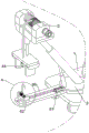
Fig. 1 is a schematic perspective view of the present invention.
Fig. 2 is a schematic perspective view of a lifting mechanism according to the present invention.
Fig. 3 is a schematic perspective view of the clamping mechanism of the present invention.
Fig. 4 is a schematic perspective view of a pull-down mechanism according to the present invention.
Fig. 5 is an enlarged schematic view of the invention at a.
Fig. 6 is a schematic perspective view of a rotating mechanism according to the present invention.
Fig. 7 is a schematic perspective view of an earth-boring mechanism according to the present invention.
Fig. 8 is a schematic perspective view of the roller mechanism of the present invention.
Reference numerals in the figures: 1. the lifting device comprises a bottom plate, 2, a rotating disc, 3, a supporting frame, 4, a lifting mechanism, 41, a first motor, 42, a lifting rope, 43, a lifting plate, 44, a lifting hook, 45, a telescopic rod, 5, a clamping mechanism, 51, a common spring, 52, a connecting rod, 53, a clamping plate, 6, a pull-down mechanism, 61, a cylinder, 62, a sliding plate, 63, a torsion spring, 64, a rotating shaft, 65, a pull rope, 66, a rotating plate, 7, a rotating mechanism, 71, a second motor, 72, a gear, 73, an arc-shaped rack, 8, an earth boring mechanism, 81, an electric push rod, 82, an earth boring cone, 83, a connecting plate, 9, a guide assembly, 91, a guide frame, 92 and a roller.
Detailed Description
The above-described aspects are further described below in conjunction with specific embodiments. It should be understood that these examples are illustrative of the present application and are not limiting the scope of the present application. The implementation conditions used in the examples may be further adjusted according to the conditions of the specific manufacturer, and the implementation conditions not specified are generally those in routine experiments.
Example 1
A crane capable of preventing horizontal shaking is shown in fig. 1-3, and comprises a bottom plate 1, a rotating disc 2, a supporting frame 3, a lifting mechanism 4 and a clamping mechanism 5, wherein wheels are arranged on the lower side of the bottom plate 1, telescopic legs are welded on the front and rear parts of the lower side of the bottom plate 1, the upper side of the left part of the bottom plate 1 is rotatably connected with the rotating disc 2, the supporting frame 3 is connected with the upper side of the rotating disc 2, the lifting mechanism 4 is arranged on the upper part of the supporting frame 3 and used for stably lifting a heavy object, the clamping mechanism 5 is arranged on the lifting mechanism 4, and the clamping mechanism 5 is used for automatically clamping and fixing the lifted heavy object.
As shown in fig. 1 and 2, the lifting mechanism 4 comprises a first motor 41, a lifting rope 42, a lifting plate 43, a lifting hook 44 and a telescopic rod 45, wherein the first motor 41 is mounted on the front side of the upper portion of the support frame 3 through bolts, an output shaft of the first motor 41 is connected with the support frame 3 in a rotating mode, the lifting rope 42 is wound on the output shaft of the first motor 41, the lifting plate 43 is connected with the lower side of the lifting rope 42, the lifting hook 44 is connected with the lower side of the middle portion of the lifting plate 43 in a sliding mode, the lifting hook 44 is used for hooking a heavy object to lift, and the telescopic rod 45 is connected between the support frame 3 and the lifting plate 43.
As shown in fig. 1 and 3, the clamping mechanism 5 comprises a common spring 51, a connecting rod 52 and clamping plates 53, wherein the common spring 51 is connected between the lifting hook 44 and the lifting plate 43, the front and rear clamping plates 53 are slidably connected to the lower side of the lifting plate 43, the clamping plates 53 move in opposite directions to clamp and fix a weight, and the connecting rod 52 is rotatably connected between the clamping plates 53 and the lifting hook 44.
When the device is used, the device is driven to move beside a heavy object under the action of wheels, then the heavy object can be suspended on the lifting hook 44, then the first motor 41 is started, the lifting rope 42 is driven to wind up by the operation of the first motor 41, so that the lifting plate 43 is driven to move upwards by the lifting rope 42, the heavy object is pulled to move upwards by the lifting hook 44, when the lifting hook 44 pulls the heavy object to move upwards, the lifting hook 44 moves downwards due to the gravity of the heavy object, the common spring 51 is stretched, and then the clamping plate 53 is driven to move inwards by the connecting rod 52, so that the heavy object is automatically clamped and fixed, the heavy object can be effectively prevented from being separated from the lifting hook 44, meanwhile, the telescopic rod 45 is driven to shrink when the lifting plate 43 moves upwards, the heavy object cannot shake horizontally under the limiting action of the telescopic rod 45, and the device is simple and convenient to operate and high in stability; when the weight is put down, the common spring 51 is restored to drive the lifting hook 44 to move upwards for resetting, and meanwhile, the connecting rod 52 drives the clamping plate 53 to move outwards for resetting, so that the weight is automatically released.
Example 2
On the basis of embodiment 1, as shown in fig. 1, 4 and 5, the utility model also comprises a pull-down mechanism 6, the pull-down mechanism 6 comprises an air cylinder 61, a sliding plate 62, a torsion spring 63, a rotating shaft 64, a pull rope 65 and a rotating plate 66, the rotating plate 66 is welded on the left side of the rotating disk 2, the air cylinder 61 is arranged on the upper side of the right part of the rotating plate 66 through bolts, the sliding plate 62 is slidingly connected on the upper left part of the rotating plate 66, the telescopic end of the air cylinder 61 is connected with the sliding plate 62, the rotating shaft 64 is rotationally connected on the sliding plate 62, the torsion spring 63 is connected between the rotating shaft 64 and the sliding plate 62, and the pull rope 65 is wound on the rotating shaft 64.
When lifting the heavy object, still steerable stay cord 65 is connected with the heavy object, and then still can pull stay cord 65 when lifting the heavy object, and then make torsion spring 63 take place deformation, and then under torsion spring 63's effect, stay cord 65 can form the power of pulling down to can form with the power of upwards promoting and pull, thereby can further guarantee the steady of heavy object, avoid the heavy object to rock, when lifting the high difference, the position of lifting also can be different, accessible control cylinder 61 drives slide 62 and removes this moment, thereby can make stay cord 65 be located under the lifting hook 44.
As shown in fig. 1 and 6, the rotary mechanism 7 is further included, the rotary mechanism 7 includes a second motor 71, a gear 72 and an arc-shaped rack 73, the second motor 71 is mounted on the upper side of the left front portion of the bottom plate 1 through bolts, the gear 72 is connected to an output shaft of the second motor 71, the arc-shaped rack 73 is welded to the outer side of the rotary disk 2, and the arc-shaped rack 73 is meshed with the gear 72.
When the position of lifting the weight is required to be adjusted, the second motor 71 can be started to operate, then the gear 72 can be driven to rotate, then the rotary disk 2 can be driven to rotate through the arc-shaped rack 73, then the support frame 3 and the rotary plate 66 can be driven to rotate, and further the position of lifting the weight is adjusted.
As shown in fig. 1 and 7, the device further comprises an earth boring mechanism 8, the earth boring mechanism 8 comprises an electric push rod 81, an earth cone 82 and a connecting plate 83, the electric push rod 81 is mounted on the lower side of the base plate 1 through bolts, the connecting plate 83 is connected to the telescopic end of the electric push rod 81, the earth cone 82 is connected to the lower side of the base plate 1 in a sliding mode, and the earth cone 82 is connected with the connecting plate 83.
When lifting heavy objects, the electric push rod 81 can be started, the connecting plate 83 is driven to move downwards through the telescopic end of the electric push rod 81, the ground cone 82 is driven to move downwards to be inserted into the soil, the stabilizing effect can be achieved on the bottom plate 1, the situation that the heavy objects shake due to the fact that the bottom plate 1 moves in the lifting process of the heavy objects is avoided, when moving equipment is needed, the electric push rod 81 is controlled to operate reversely, and then the connecting plate 83 and the ground cone 82 are driven to move upwards to reset.
As shown in fig. 1 and 8, the lifting rope lifting device further comprises a guide assembly 9, the guide assembly 9 comprises a guide frame 91 and a roller 92, the guide frame 91 is welded on the left side of the upper part of the support frame 3, the roller 92 is rotatably connected to the guide frame 91, and the lifting rope 42 is located between the guide frame 91 and the roller 92.
The guide frame 91 and the roller 92 can limit the lifting rope 42, so that the condition that the lifting rope 42 moves to cause shaking when a heavy object is lifted is avoided, and meanwhile, the roller 92 can rotate, so that the movement winding of the lifting rope 42 is not affected.
Finally, it should be noted that the above embodiments are only for illustrating the technical solution of the present invention and not for limiting the scope of the present invention, and although the present invention has been described in detail with reference to the preferred embodiments, it should be understood by those skilled in the art that the technical solution of the present invention may be modified or substituted equally without departing from the spirit and scope of the technical solution of the present invention.
Claims (8)
1. Can prevent hoist that level rocked, including bottom plate (1), rotary disk (2) and support frame (3), both parts all are connected with flexible leg around the downside of bottom plate (1), and the left portion upside rotation of bottom plate (1) is connected with rotary disk (2), and the upside of rotary disk (2) is connected with support frame (3), its characterized in that: the lifting device also comprises a lifting mechanism (4) and a clamping mechanism (5), wherein the lifting mechanism (4) for stably lifting the weight is arranged on the upper portion of the supporting frame (3), and the clamping mechanism (5) for automatically clamping and fixing the lifted weight is arranged on the lifting mechanism (4).
2. A crane capable of preventing horizontal sway according to claim 1, characterized in that: the lifting mechanism (4) comprises a first motor (41), a lifting rope (42), a lifting plate (43), a lifting hook (44) and a telescopic rod (45), wherein the first motor (41) is installed on the front side of the upper portion of the support frame (3), an output shaft of the first motor (41) is connected with the support frame (3) in a rotating mode, the lifting rope (42) is wound on the output shaft of the first motor (41), the lifting plate (43) is connected to the lower side of the lifting rope (42), the lifting hook (44) is connected to the lower side of the middle portion of the lifting plate (43) in a sliding mode, and the telescopic rod (45) is connected between the support frame (3) and the lifting plate (43).
3. A crane capable of preventing horizontal sway according to claim 2, characterized in that: the clamping mechanism (5) comprises a common spring (51), a connecting rod (52) and clamping plates (53), wherein the common spring (51) is connected between the lifting hook (44) and the lifting plate (43), the front clamping plate (53) and the rear clamping plate (53) are connected on the lower side of the lifting plate (43) in a sliding mode, and the connecting rod (52) is connected between the clamping plates (53) and the lifting hook (44) in a rotating mode.
4. A crane capable of preventing horizontal sway according to claim 3, characterized in that: the automatic pulling device is characterized by further comprising a pulling-down mechanism (6), wherein the pulling-down mechanism (6) comprises an air cylinder (61), a sliding plate (62), a torsion spring (63), a rotating shaft (64), a pull rope (65) and a rotating plate (66), the left side of the rotating disc (2) is connected with the rotating plate (66), the air cylinder (61) is installed on the upper side of the right part of the rotating plate (66), the sliding plate (62) is slidingly connected on the upper side of the left part of the rotating plate (66), the telescopic end of the air cylinder (61) is connected with the sliding plate (62), the rotating shaft (64) is rotatably connected on the sliding plate (62), the torsion spring (63) is connected between the rotating shaft (64) and the sliding plate (62), and the pull rope (65) is wound on the rotating shaft (64).
5. A crane capable of preventing horizontal sway according to claim 4, characterized in that: the rotary mechanism (7) comprises a second motor (71), a gear (72) and an arc-shaped rack (73), the second motor (71) is arranged on the upper side of the left front part of the bottom plate (1), the gear (72) is connected to the output shaft of the second motor (71), the arc-shaped rack (73) is connected to the outer side of the rotary plate (2), and the arc-shaped rack (73) is meshed with the gear (72).
6. A crane capable of preventing horizontal sway according to claim 5, characterized in that: the underground drilling device is characterized by further comprising an underground drilling mechanism (8), wherein the underground drilling mechanism (8) comprises an electric push rod (81), an underground cone (82) and a connecting plate (83), the electric push rod (81) is installed on the lower side of the bottom plate (1), the connecting plate (83) is connected to the telescopic end of the electric push rod (81), the underground cone (82) is connected to the lower side of the bottom plate (1) in a sliding mode, and the underground cone (82) is connected with the connecting plate (83).
7. A crane capable of preventing horizontal sway according to claim 6, characterized in that: the lifting rope device is characterized by further comprising a guide assembly (9), wherein the guide assembly (9) comprises a guide frame (91) and rollers (92), the guide frame (91) is connected to the left side of the upper portion of the support frame (3), the rollers (92) are rotatably connected to the guide frame (91), and the lifting rope (42) is located between the guide frame (91) and the rollers (92).
8. A crane capable of preventing horizontal sway according to claim 7, characterized in that: wheels are arranged on the lower side of the bottom plate (1).
Priority Applications (1)
| Application Number | Priority Date | Filing Date | Title |
|---|---|---|---|
| CN202310089953.9A CN116062604A (en) | 2023-02-09 | 2023-02-09 | Crane capable of preventing horizontal shaking |
Applications Claiming Priority (1)
| Application Number | Priority Date | Filing Date | Title |
|---|---|---|---|
| CN202310089953.9A CN116062604A (en) | 2023-02-09 | 2023-02-09 | Crane capable of preventing horizontal shaking |
Publications (1)
| Publication Number | Publication Date |
|---|---|
| CN116062604A true CN116062604A (en) | 2023-05-05 |
Family
ID=86176606
Family Applications (1)
| Application Number | Title | Priority Date | Filing Date |
|---|---|---|---|
| CN202310089953.9A Pending CN116062604A (en) | 2023-02-09 | 2023-02-09 | Crane capable of preventing horizontal shaking |
Country Status (1)
| Country | Link |
|---|---|
| CN (1) | CN116062604A (en) |
Cited By (2)
| Publication number | Priority date | Publication date | Assignee | Title |
|---|---|---|---|---|
| CN116605776A (en) * | 2023-07-21 | 2023-08-18 | 青岛汇金通电力设备股份有限公司 | Crane for power tower construction |
| CN116946888A (en) * | 2023-09-20 | 2023-10-27 | 邹城市巨力机械有限公司 | Movable heavy object promotes portal frame |
-
2023
- 2023-02-09 CN CN202310089953.9A patent/CN116062604A/en active Pending
Cited By (4)
| Publication number | Priority date | Publication date | Assignee | Title |
|---|---|---|---|---|
| CN116605776A (en) * | 2023-07-21 | 2023-08-18 | 青岛汇金通电力设备股份有限公司 | Crane for power tower construction |
| CN116605776B (en) * | 2023-07-21 | 2023-09-15 | 青岛汇金通电力设备股份有限公司 | Crane for power tower construction |
| CN116946888A (en) * | 2023-09-20 | 2023-10-27 | 邹城市巨力机械有限公司 | Movable heavy object promotes portal frame |
| CN116946888B (en) * | 2023-09-20 | 2023-12-15 | 邹城市巨力机械有限公司 | Movable heavy object promotes portal frame |
Similar Documents
| Publication | Publication Date | Title |
|---|---|---|
| CN116062604A (en) | Crane capable of preventing horizontal shaking | |
| CN214879790U (en) | Movable arm tower crane | |
| CN113771736A (en) | Cable reel conveying device for erecting power transmission lines in mountainous areas | |
| CN117246905A (en) | Luffing trolley and control method thereof | |
| CN216512394U (en) | Crane with anti-swing device | |
| CN214935546U (en) | Hoisting trolley for unit curtain wall | |
| CN216613823U (en) | Vehicle-mounted truck crane for vehicle-mounted transportation, loading and unloading | |
| CN212292579U (en) | Adjustable support of crane | |
| CN209957271U (en) | Instrument lifting device for oil field work | |
| CN109704204B (en) | Container door machine with supporting platform and working method thereof | |
| CN218201889U (en) | Hoisting structure | |
| CN206233873U (en) | A kind of hook block simple floating guide device of vehicle carried well repairing machine traveling system | |
| CN110550562A (en) | multifunctional crane assembled on forklift | |
| CN220432142U (en) | Building construction tower crane | |
| CN214570251U (en) | Derrick mast lifting mechanism convenient to operate | |
| CN212245989U (en) | Vehicle is with portable goods handling device | |
| CN220058768U (en) | Pulley type hanging basket hanging device | |
| CN216105744U (en) | Convenient and movable hoisting equipment | |
| CN218465377U (en) | Large rectangular pipe jacking pipe joint hoisting device | |
| CN217201688U (en) | Electric double-beam hoisting device | |
| CN116969355B (en) | Lifting mechanism of bridge inspection vehicle | |
| CN220223286U (en) | Fan overhauls auxiliary assembly | |
| CN221191289U (en) | Light portal crane | |
| CN219174067U (en) | Electric gantry crane | |
| CN113247794B (en) | Combined hoisting equipment for steel structure roof for building and construction method thereof |
Legal Events
| Date | Code | Title | Description |
|---|---|---|---|
| PB01 | Publication | ||
| PB01 | Publication | ||
| SE01 | Entry into force of request for substantive examination | ||
| SE01 | Entry into force of request for substantive examination |