CN216512394U - Crane with anti-swing device - Google Patents
Crane with anti-swing device Download PDFInfo
- Publication number
- CN216512394U CN216512394U CN202220688745.1U CN202220688745U CN216512394U CN 216512394 U CN216512394 U CN 216512394U CN 202220688745 U CN202220688745 U CN 202220688745U CN 216512394 U CN216512394 U CN 216512394U
- Authority
- CN
- China
- Prior art keywords
- telescopic
- telescopic joint
- wire rope
- steel wire
- limiting block
- Prior art date
- Legal status (The legal status is an assumption and is not a legal conclusion. Google has not performed a legal analysis and makes no representation as to the accuracy of the status listed.)
- Active
Links
Images


Abstract
The utility model discloses a crane with an anti-swing device, which comprises a main beam and an end beam, wherein a trolley is arranged on the main beam, a winding drum is rotatably connected on the trolley, and a telescopic rod is arranged at the bottom of a trolley frame; the telescopic rod comprises a plurality of telescopic joints which are matched in a telescopic mode in the vertical direction, the telescopic joint with the larger outer diameter is marked as an upper sleeve, the telescopic joint with the smaller outer diameter is marked as a lower sleeve, the upper sleeve is sleeved outside the lower sleeve, an upper limiting block and a lower limiting block are arranged on the inner wall of the upper sleeve, a sliding block is arranged on the outer wall of the lower sleeve and slides between the upper limiting block and the lower limiting block, and a lifting appliance is arranged at the bottom end of the telescopic joint at the innermost part; a steel wire rope is wound on the winding drum, the steel wire rope is arranged inside the telescopic joint, and the bottom end of the steel wire rope is arranged at the bottom of the innermost telescopic joint through a connecting piece; the utility model is used for solving the problems that the stability of a steel wire rope is insufficient, and a lifting hook and a heavy object are easy to shake in the prior art, so that the lifting safety of the heavy object is influenced.
Description
Technical Field
The utility model relates to the technical field of hoisting equipment, in particular to a crane with an anti-swing device.
Background
The crane refers to a multi-action hoisting machine for vertically lifting and horizontally carrying heavy objects within a certain range, which is also called a crown block, a crane and a crane, and the hoisting equipment has the working characteristics of intermittent motion, namely corresponding mechanisms for taking materials, transporting, unloading and the like in one working cycle work alternately, so that the crane is more and more widely developed and used in the market. The existing crane mostly adopts a steel wire rope to pull a lifting hook to lift a heavy object, although the steel wire rope has high bearing safety coefficient in the vertical direction, the lifting hook is easy to shake in the horizontal direction, the lifting hook and an object can swing greatly, and the object is easy to unhook; and the object is in a relatively uncontrollable state this moment, and the load that wire rope received is also constantly changing, leads to the cracked condition of wire rope easily, influences the security of heavy object jack-up.
SUMMERY OF THE UTILITY MODEL
The utility model aims to provide a crane with an anti-swing device, which is used for solving the problems that in the prior art, the stability of a steel wire rope is insufficient, a lifting hook and a heavy object are easy to swing, and the lifting safety of the heavy object is influenced.
In order to achieve the purpose, the utility model adopts the following technical scheme: a crane with an anti-swing device comprises a main beam and an end beam, wherein a trolley is arranged on the main beam and comprises a trolley frame, a winding drum is rotatably connected onto the trolley frame, a speed reducer is mounted at one end of the winding drum, a driving motor is mounted on the speed reducer, and a telescopic rod is arranged at the bottom of the trolley frame; the telescopic rod comprises a plurality of telescopic joints which are matched in a telescopic mode in the vertical direction, the telescopic joint with the larger outer diameter is marked as an upper sleeve, the telescopic joint with the smaller outer diameter is marked as a lower sleeve, the upper sleeve is sleeved outside the lower sleeve, an upper limiting block and a lower limiting block are arranged on the inner wall of the upper sleeve, a sliding block is arranged on the outer wall of the lower sleeve and slides between the upper limiting block and the lower limiting block, and a lifting appliance is arranged at the bottom end of the telescopic joint at the innermost part; the winding drum is wound with a steel wire rope, the steel wire rope is arranged in the telescopic joint, and the bottom end of the steel wire rope is arranged at the bottom of the innermost telescopic joint through a connecting piece.
Optionally, a slewing bearing is arranged between the trolley frame and the telescopic rod, a rotating motor is arranged at the top of the slewing bearing, and the telescopic rod is fixedly connected to the bottom of the slewing bearing; the connecting piece is rotatably connected to the bottom of the innermost telescopic joint.
Optionally, the lifting appliance comprises a mounting plate and a lifting hook, the mounting plate is fixedly connected to the bottom end of the telescopic joint, and the lifting hook is arranged at the bottom of the mounting plate.
Optionally, the top of the hook is hinged to the bottom of the mounting plate, and an adjusting push rod is hinged between the hook and the mounting plate.
Optionally, the cross-section of the telescopic joint is a rectangular structure.
The crane with the anti-swing device has the following advantages:
(1) the hoist sets up in the telescopic link bottom, and wire rope sets up in the inside of telescopic link, and wire rope can drive the telescopic link and reciprocate, realizes the lift action of heavy object, and the stability of telescopic link is high than wire rope's stability, so the condition of acutely rocking can not appear, ensures the stable, safe handling of heavy object.
(2) Slewing bearing can drive the telescopic link rotatory, makes the hoist possess rotation function, provides equipment function diversity.
(3) The angle of the lifting hook can be adjusted by adjusting the push rod, and before or after the lifting is started or completed, the heavy object can be hung on or taken down from the lifting hook more easily by adjusting the angle of the lifting hook; during the hoisting, the angle of the lifting hook is adjusted to ensure that the heavy object is stably hung on the lifting appliance and is not easy to fall off.
Drawings
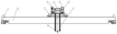
Fig. 1 is a schematic structural view of the present invention.
Fig. 2 is a schematic view of the connection of a spreader to a telescopic bar.
FIG. 3 is a schematic view showing the connection of the wire rope to the innermost telescopic joint in the first embodiment.
FIG. 4 is a schematic view showing the connection between the trolley and the telescopic rod according to the second embodiment.
FIG. 5 is a schematic view showing the connection of the wire rope to the innermost telescopic joint in the second embodiment.
Detailed Description
The utility model is further described below with reference to the accompanying drawings.
The first embodiment is as follows:
as shown in fig. 1-3, a hoist with anti-swing device, including girder 2 and end beam 1, be provided with trolley 3 on the girder 2, trolley 3 includes the dolly frame, it is connected with reel 6 to rotate on the dolly frame, the speed reducer is installed to the one end of reel 6, install driving motor 5 on the speed reducer, telescopic link 9 includes a plurality of telescopic joints 11 along the flexible complex of vertical direction, the cross section of telescopic joint 11 is the rectangle structure, the rectangle structure can prevent telescopic joint 11 self from rotating, ensure that telescopic link 9 only can rise or descend along vertical direction, improve telescopic link 9's stability. The big record of external diameter is gone up the sleeve in the adjacent telescopic joint 11, and the little record of external diameter is gone up the sleeve in the adjacent telescopic joint 11, and the sleeve cover is established in the sleeve outside down, is provided with upper stop block and lower stop block on the upper telescopic inner wall, is provided with the slider on the telescopic outer wall down, and the slider slides between upper stop block and lower stop block. The winding drum 6 is wound with a steel wire rope 14, the steel wire rope 14 hanging from the winding drum 6 is arranged inside the telescopic joint 11, and the bottom end of the steel wire rope 14 is installed at the bottom of the telescopic joint 11 at the innermost part through a connecting piece 16.
Bottom fixedly connected with hoist 10 of telescopic joint 11 innermost, hoist 10 include mounting panel 12 and lifting hook 13, and mounting panel 12 fixed connection is in telescopic joint 11 innermost's bottom, and lifting hook 13 articulates in mounting panel 12 bottom, and the length of mounting panel 12 is greater than the width of telescopic link 9, and mounting panel 12 has certain limiting displacement, avoids telescopic joint 11 innermost to promote excessively and damage. An adjusting push rod 15 is hinged between the lifting hook 13 and the mounting plate 12, the angle of the lifting hook 13 can be adjusted by the adjusting push rod 15, and before or after the lifting is started or completed, the heavy object can be hung on the lifting hook 13 or taken down from the lifting hook 13 more easily by adjusting the angle of the lifting hook 13; during the lifting, the angle of the lifting hook 13 is adjusted to ensure that the heavy object is stably hung on the lifting appliance 10 and is not easy to fall off.
The principle of the utility model is as follows: when the winding drum 6 releases the rope, the telescopic rod 9 moves downwards under the action of the gravity of the telescopic rod and the lifting appliance 10; when the winding drum 6 is reeled, the telescopic rod 9 and the lifting appliance 10 move upwards under the action of the steel wire rope 14, so that the lowering and lifting of the heavy object are completed. The telescopic rod 9 is of a rigid structure, and the lifting appliance 10 is fixedly connected to the bottom end of the innermost telescopic joint 11, so that violent shaking in the horizontal direction cannot occur to the lifting appliance 10 in the lifting process, and the lifting stability and safety of a heavy object are ensured.
Example two:
as shown in fig. 4-5, the structure of the present embodiment is substantially the same as that of the first embodiment, except that: a slewing bearing 7 is arranged between the trolley frame and a telescopic rod 9, the outer ring of the slewing bearing 7 is fixedly connected to the bottom of the trolley frame, and the telescopic rod 9 is fixedly connected to the bottom of the inner ring of the slewing bearing 7. Slewing bearing 7 top is provided with rotating electrical machines 8, and under rotating electrical machines 8's effect, slewing bearing 7 can drive telescopic link 9 and rotate, and then drives hoist 10 and rotate, and hoist 10 can rotate and make the function of equipment more diversified, has made things convenient for lifting by crane and transporting of heavy object. The connecting piece 16 in this embodiment needs to be connected to the bottom of the innermost telescopic joint 11 in a rotating manner, so that when the telescopic rod 9 rotates, the connecting piece 16 can enable the steel wire rope 14 not to rotate along with the telescopic rod 9, and thus the steel wire rope 14 only needs to bear a load in the vertical direction and cannot rotate by itself, and the conditions of torsion and rope disorder of the steel wire rope 14 cannot occur.
The embodiments described above are only a part of the embodiments of the present invention, and not all of them. All other embodiments that can be obtained by a person skilled in the art based on the embodiments of the present invention without any creative effort belong to the protection scope of the present invention.
Claims (5)
1. The utility model provides a hoist with prevent device that sways, includes girder and end beam, is provided with trolley, its characterized in that on the girder: the hoisting trolley comprises a trolley frame, a winding drum is rotatably connected onto the trolley frame, one end of the winding drum is provided with a speed reducer, the speed reducer is provided with a driving motor, and the bottom of the trolley frame is provided with a telescopic rod; the telescopic rod comprises a plurality of telescopic joints which are matched in a telescopic mode in the vertical direction, the telescopic joint with the larger outer diameter is marked as an upper sleeve, the telescopic joint with the smaller outer diameter is marked as a lower sleeve, the upper sleeve is sleeved outside the lower sleeve, an upper limiting block and a lower limiting block are arranged on the inner wall of the upper sleeve, a sliding block is arranged on the outer wall of the lower sleeve and slides between the upper limiting block and the lower limiting block, and a lifting appliance is arranged at the bottom end of the telescopic joint at the innermost part; the winding drum is wound with a steel wire rope, the steel wire rope is arranged in the telescopic joint, and the bottom end of the steel wire rope is arranged at the bottom of the innermost telescopic joint through a connecting piece.
2. A crane with an anti-sway device as claimed in claim 1 wherein: a rotary support is arranged between the trolley frame and the telescopic rod, a rotating motor is arranged at the top of the rotary support, and the telescopic rod is fixedly connected to the bottom of the rotary support; the connecting piece is connected at the bottom of the telescopic joint at the innermost part in a rotating mode.
3. A crane with an anti-sway device as claimed in claim 1 wherein: the lifting appliance comprises a mounting plate and a lifting hook, the mounting plate is fixedly connected to the bottom end of the telescopic joint, and the lifting hook is arranged at the bottom of the mounting plate.
4. A crane with an anti-sway device as claimed in claim 3 wherein: the top of lifting hook articulates the bottom at the mounting panel, and it has the adjustment push rod to articulate between lifting hook and the mounting panel.
5. A crane with an anti-sway device as claimed in claim 1 wherein: the cross section of the telescopic joint is of a rectangular structure.
Priority Applications (1)
| Application Number | Priority Date | Filing Date | Title |
|---|---|---|---|
| CN202220688745.1U CN216512394U (en) | 2022-03-28 | 2022-03-28 | Crane with anti-swing device |
Applications Claiming Priority (1)
| Application Number | Priority Date | Filing Date | Title |
|---|---|---|---|
| CN202220688745.1U CN216512394U (en) | 2022-03-28 | 2022-03-28 | Crane with anti-swing device |
Publications (1)
| Publication Number | Publication Date |
|---|---|
| CN216512394U true CN216512394U (en) | 2022-05-13 |
Family
ID=81519463
Family Applications (1)
| Application Number | Title | Priority Date | Filing Date |
|---|---|---|---|
| CN202220688745.1U Active CN216512394U (en) | 2022-03-28 | 2022-03-28 | Crane with anti-swing device |
Country Status (1)
| Country | Link |
|---|---|
| CN (1) | CN216512394U (en) |
Cited By (1)
| Publication number | Priority date | Publication date | Assignee | Title |
|---|---|---|---|---|
| CN116534719A (en) * | 2023-07-06 | 2023-08-04 | 河南省大方重型机器有限公司 | Automatic change coil of strip and hang transport crane |
-
2022
- 2022-03-28 CN CN202220688745.1U patent/CN216512394U/en active Active
Cited By (1)
| Publication number | Priority date | Publication date | Assignee | Title |
|---|---|---|---|---|
| CN116534719A (en) * | 2023-07-06 | 2023-08-04 | 河南省大方重型机器有限公司 | Automatic change coil of strip and hang transport crane |
Similar Documents
| Publication | Publication Date | Title |
|---|---|---|
| CN216512394U (en) | Crane with anti-swing device | |
| CN115676644B (en) | Anti-swing outdoor portal crane | |
| CN210480697U (en) | Material lifting machine for building engineering construction | |
| CN209024048U (en) | A kind of high stability tubing derrick crane | |
| CN213231211U (en) | Lifting hook anti-swing device for bridge crane | |
| CN109110634A (en) | A kind of high stability tubing derrick crane | |
| CN113135517A (en) | Electric chain hoist | |
| CN210286537U (en) | Four-point crane for hoisting bin cover of transport ship | |
| CN113086861A (en) | Cantilever crane | |
| CN217478834U (en) | Railway freight container lifting appliance | |
| CN205916920U (en) | Walking hoist and mount boat car | |
| CN220149048U (en) | Hoisting mechanism capable of slowing down shaking | |
| CN214780352U (en) | Gantry crane with lifting appliance stability maintaining structure | |
| CN208037886U (en) | A kind of boom of hoister | |
| CN217780622U (en) | Endless chain electric hoist | |
| CN211769830U (en) | Variable-amplitude gantry crane for component transfer | |
| CN217627294U (en) | Windproof tower crane for constructional engineering | |
| CN214456285U (en) | Crane with rotary trolley | |
| CN216190572U (en) | Crane with good stability | |
| CN220300239U (en) | Shipbuilding gantry crane | |
| CN218931502U (en) | Anti-swing lifting appliance upper frame | |
| CN203095424U (en) | Elevating mechanism of gantry rack | |
| CN213569239U (en) | Crane | |
| CN217264344U (en) | Small-sized aerial crane for lifting ton bags | |
| CN220703070U (en) | Lorry-mounted crane suitable for lifting power equipment |
Legal Events
| Date | Code | Title | Description |
|---|---|---|---|
| GR01 | Patent grant | ||
| GR01 | Patent grant |