CN115924597B - Coiling mechanism of plastics composite bag production line - Google Patents
Coiling mechanism of plastics composite bag production line Download PDFInfo
- Publication number
- CN115924597B CN115924597B CN202310246651.8A CN202310246651A CN115924597B CN 115924597 B CN115924597 B CN 115924597B CN 202310246651 A CN202310246651 A CN 202310246651A CN 115924597 B CN115924597 B CN 115924597B
- Authority
- CN
- China
- Prior art keywords
- frame
- machine base
- composite bag
- production line
- plastic composite
- Prior art date
- Legal status (The legal status is an assumption and is not a legal conclusion. Google has not performed a legal analysis and makes no representation as to the accuracy of the status listed.)
- Active
Links
Images


Abstract
The invention discloses a winding device of a plastic composite bag production line, which comprises a machine base, wherein a winding component is rotatably arranged on one side of the upper part of the machine base, an adjusting component for adjusting the angle of the winding component is arranged on the lower part of the inner side of the machine base, a material breaking component is arranged on the upper part of the machine base, a semicircular arc part is arranged at one end of the upper part of the machine base, a metal roll shaft is coaxially rotatably arranged at the position of the semicircular arc part, a supporting frame is fixed at the position, close to the inner side of the machine base, of the metal roll shaft, the supporting frame is of a U-shaped frame structure, the supporting frame comprises a horizontal flat part, an inclined part which is inclined upwards is arranged at one end, far away from the machine base, of the horizontal flat part, and locking roll components are symmetrically arranged at two sides of the supporting frame, close to the inclined part and the horizontal flat part. The plastic composite bag cutting machine is convenient to discharge, can clamp the plastic composite bag before stamping, ensures the cutting effect, and avoids the problem of uneven cuts.
Description
Technical Field
The invention relates to the technical field of winding equipment, in particular to a winding device of a plastic composite bag production line.
Background
Plastic bags are an indispensable article in people's daily life and are often used for containing other articles. The plastic composite bag belongs to a common plastic bag, and is suitable for vacuum packaging or general packaging of foods, electronic products, chemical industry, medicines, tea, precise instruments and national defense tip products because of the advantages of low cost, light weight, large capacity and convenience in storage. In the bag making technology of plastic bags, when the preamble of plastic composite bags is finished, the plastic bags are usually required to be wound, the existing winding device needs manual taking and unreeling rollers, and the problems of uneven cuts and the like easily occur in the cutting process, so that the winding device of the plastic composite bag production line is provided.
Disclosure of Invention
Based on the technical problems in the background art, the invention provides a winding device of a plastic composite bag production line.
The invention provides a winding device of a plastic composite bag production line, which comprises a machine base, wherein a winding component is rotatably arranged on one side of the upper part of the machine base, an adjusting component for adjusting the angle of the winding component is arranged on the lower part of the inner side of the machine base, and a material breaking component is arranged on the upper part of the machine base;
the upper end of the machine base is provided with a semicircular arc part, the semicircular arc part is coaxially provided with a metal roll shaft in a rotating manner, a supporting frame is fixed at the inner side of the metal roll shaft close to the machine base and is of a U-shaped frame structure, the supporting frame comprises a transverse flat part, an inclined part inclined upwards in an inclined manner is arranged at one end of the transverse flat part far away from the machine base, locking roll assemblies are symmetrically arranged at two sides of the supporting frame close to the inclined part and the transverse flat part, each locking roll assembly comprises a rotary disc, round holes for the rotary disc to be connected in a rotating manner are formed in the side wall of the supporting frame, the rotary table is characterized in that a slot is formed in one end of the rotary table, the slot is of a polygonal structure, a polygon column is inserted in the slot, a pulling column is rotationally arranged at the middle position of one end of the polygon column, a jack communicated with the inside of the slot is formed in the rotary table, one end of the pulling column penetrates through the jack, a first reset spring is arranged at the position, close to the inside of the slot, of the peripheral surface of the pulling column, a roller-removing assembly for driving the pulling column to axially move along the roller-removing assembly is arranged on the horizontal flat portion, and a driving assembly for driving one rotary table to rotate is arranged on the upper portion of the supporting frame.
As a further optimization of the technical scheme, the rolling device of the plastic composite bag production line comprises a sliding frame arranged on the horizontal flat part in a sliding mode, wherein a transverse arm is arranged at one end, close to a machine seat, of the sliding frame, a disc is rotatably arranged on the transverse arm, the outer circumferential surface of the disc is in contact with the outer circumferential surface of a semicircular arc part, a sliding block is arranged on the side wall of the sliding frame, a strip-shaped slideway is arranged on the side wall of the horizontal flat part along the length direction of the side wall of the sliding frame, the sliding block is arranged in the strip-shaped slideway in a sliding mode, a third reset spring is fixed on the inner wall of one end, far away from a metal roller shaft, of the strip-shaped slideway, a first protruding part is arranged at the lower portion of the semicircular arc part, a trigger rod is arranged at one end, far from the transverse arm, a second protruding part is arranged on the trigger rod, a strip-shaped channel is arranged on the pulling column, and the trigger rod is inserted in the strip-shaped channel.
In the preferred scheme, along with the rotating process of the supporting frame, the disc is contacted with the first protruding part to drive the sliding frame to move, so that the pulling column and the polygon prism are pulled to move under the action of the trigger rod and the second protruding part.
As a further optimization of the technical scheme, the winding device of the plastic composite bag production line comprises the supporting frame fixed at the lower part of the supporting frame, the inner side of the bottom of the machine seat is provided with the hinging seat, the hinging seat is internally hinged with the air cylinder, and the upper part of the air cylinder is hinged with the lower part of the supporting frame.
As a further optimization of the technical scheme, the winding device of the plastic composite bag production line is characterized in that one side, far away from a metal roll shaft, of the supporting frame is provided with the handrail frame.
As a further optimization of the technical scheme, the rolling device of the plastic composite bag production line is characterized in that a metal cover is arranged on the upper portion of the supporting frame, the driving assembly comprises a driving motor arranged at one end of the upper portion of the metal cover, a belt pulley is fixed on an output shaft of the driving motor through a bolt, and the belt pulley and one turntable are sleeved with the same belt.
As a further optimization of the technical scheme, the rolling device of the plastic composite bag production line is characterized in that the same roll shaft assembly is arranged between the two lock roll assemblies, the roll shaft assembly comprises a hollow roll, polygonal grooves matched with the polygonal columns are formed in two ends of the hollow roll, expansion assemblies which are distributed in an annular mode at equal intervals are arranged on the outer circumferential surface of the hollow roll, the expansion assemblies comprise expansion battens, strip-shaped holes for sliding the expansion battens are formed in the outer circumferential surface of the hollow roll, trapezoid block groups which are distributed symmetrically are arranged on one side, close to the inner side of the hollow roll, of each strip-shaped hole, through holes are formed in the hollow roll along the axial direction of each trapezoid block, two contact rods which are distributed symmetrically are arranged in the through holes, one second reset spring is arranged between each two contact rods, and frustum-shaped protrusions are arranged on the outer circumferential surface of each contact rod, close to the trapezoid block positions.
In the preferred scheme, when the touch rod moves under pressure, the frustum-shaped protrusions are matched with the trapezoid block group, so that the expansion battens can be driven to expand outwards, and the inner side of the roller core can be fixed in a tensioning mode.
According to the winding device for the plastic composite bag production line, the material cutting assembly comprises the retainer arranged on the upper portion of the inner side of the machine base, the retainer comprises the rectangular retainer frame, the top of the rectangular retainer frame is of an opening structure, guide rods which are vertically arranged are arranged at two ends of the inner wall of the bottom of the rectangular retainer frame, the same cross beam is fixed on the upper portions of the two guide rods, the same gate-type energy charging frame is arranged on the guide rods in a sliding mode, rectangular material passing holes penetrating through the guide rods are formed in the side wall of the rectangular retainer frame, positioning cutting grooves are formed in the lower portion of the inner side of the rectangular retainer frame, a material cutting knife rest is arranged on the inner side of the rectangular retainer frame in a sliding mode, the material cutting knife rest comprises a transverse plate, guide holes for the guide rods to penetrate through are formed in the two ends of the transverse plate, energy charging springs are sleeved on the outer peripheral surfaces of the guide rods and are respectively fixed with the gate-type energy charging frame and the transverse plate, a cutter knife rest is arranged on the lower portion of the transverse plate, one side of the transverse plate is provided with a U-shaped frame, and two sides of the U-shaped frame are far away from the machine base are arranged along with the position of the vertical locking frame, and the two sides of the machine base are locked by the vertical locking frame are arranged along with the position of the two sides of the vertical locking frame, and the two sides of the vertical frame are arranged along with the position of the vertical locking frame is opposite to the side of the machine base, and the two side of the machine frame is opposite side opposite to the side, and the side of the machine frame is opposite to the machine frame, and the machine frame is opposite to the side, and the machine frame to the machine frame.
In the preferred scheme, the door type energy charging frame can press and charge the energy charging spring in the process of moving downwards, and when the locking component does not block the material cutting tool rest any more, the material cutting tool rest moves downwards under the action of the energy charging spring to drive the material cutting tool to cut off the plastic composite bag.
As a further optimization of the technical scheme, the winding device of the plastic composite bag production line comprises a crank arm rotatably arranged on the inner side of a machine base, wherein one side, close to a rectangular holding frame, of the upper portion of the crank arm is provided with a bevel portion, the upper portion of the bevel portion is provided with a step groove, the lower end of the crank arm is provided with a semicircular clamping groove, a reset plate spring is clamped in the semicircular clamping groove, and the other end of the reset plate spring is fixedly connected with the inner wall of one side of the machine base.
In the preferred scheme, when the crank arm is driven to rotate by the rotating and downward-moving supporting frame, the support of the cutting tool rest can be released, and when the crank arm is not pressed any more, the reset plate spring provides an elastic force for rotating and resetting the crank arm.
As a further optimization of the technical scheme, the rolling device of the plastic composite bag production line comprises a linkage gear set, wherein the linkage gear set comprises a second gear fixedly connected with one end of a metal roll shaft, a first gear is rotatably arranged on the side wall of a machine base and meshed with the second gear, tooth parts are arranged on the side wall of a door type energy charging frame, close to the first gear, and meshed with the first gear, and rectangular openings matched with the door type energy charging frame are formed in two ends of the upper portion of the rectangular holding frame.
In this preferred scheme, along with the rotation of carriage, drive the rotation of metal roller to drive first gear and second gear rotation, then the tooth portion that the cooperation set up drives the door type and fills can the frame and move down or move up.
As a further optimization of the technical scheme, the rolling device of the plastic composite bag production line is characterized in that a material pressing assembly is arranged at the position, close to a material breaking assembly, of the inner side of a machine base, the material pressing assembly comprises a transverse supporting plate fixed at the inner side of the machine base, the upper surface of the transverse supporting plate is flush with the lower side of a rectangular material passing hole, the material pressing assembly further comprises a lower pressing plate rotatably arranged above the transverse supporting plate, a rotating shaft is fixed at the upper side of the lower pressing plate and is rotatably connected with the inner side of the machine base, a trigger plate is arranged at the upper side of the rotating shaft, an included angle between the trigger plate and the lower pressing plate is smaller than 90 degrees, a rectangular opening is formed in one side, far away from the trigger plate, of the lower pressing plate, a material pressing roller is rotatably arranged in the rectangular opening, and a touch pressing block is arranged at one side, close to the trigger plate, of the upper part of the door type energy charging frame.
In this preferred scheme, the contact briquetting of moving down can drive the trigger plate rotation to drive the clamp down board rotation, the swage roller that the cooperation set up compresses tightly the plastics composite bag.
In summary, the beneficial effects of the invention are as follows:
the invention provides a winding device of a plastic composite bag production line, which is characterized in that a sliding frame and a trigger rod can be pushed to move along with the rotation of a cylinder driving winding assembly through a semicircular arc part and a first bulge part which are matched with each other, a pulling column and a polygon column are pulled to move, so that the polygon column and the roller shaft assembly are separated, and the discharging is convenient.
Drawings
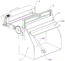
FIG. 1 is a schematic structural view of a winding device of a plastic composite bag production line;
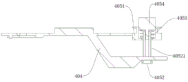
fig. 2 is a schematic side view of a winding device of a plastic composite bag production line according to the present invention;
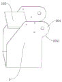
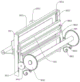
FIG. 3 is a schematic structural view of a frame of a winding device of a plastic composite bag production line according to the present invention;
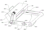
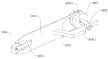
fig. 4 is a schematic structural view of a winding assembly of a winding device of a plastic composite bag production line according to the present invention;
FIG. 5 is a schematic structural view of a rolling device roller assembly of a plastic composite bag production line according to the present invention;
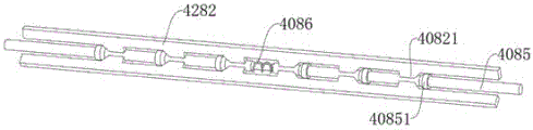
FIG. 6 is a schematic view of a structure of a rolling device roller assembly of a plastic composite bag production line with hollow rollers removed;
FIG. 7 is a schematic structural view of a take-up device take-off roller assembly and a lock roller assembly of a plastic composite bag production line according to the present invention;
FIG. 8 is a schematic cross-sectional view of a take-up device take-off assembly and a lock roller assembly of a plastic composite bag production line according to the present invention;
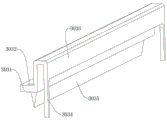
FIG. 9 is a schematic structural view of a material breaking assembly of a winding device in a plastic composite bag production line according to the present invention;
FIG. 10 is a schematic structural view of a winding device holder of a plastic composite bag production line according to the present invention;
FIG. 11 is a schematic structural view of a cutter frame of a winding device of a plastic composite bag production line;
fig. 12 is a schematic structural diagram of a material pressing assembly of a winding device in a plastic composite bag production line.
In the figure: 1. a base; 101. a hinge base; 102. a transverse supporting plate; 103. a cylinder; 104. a semicircular arc portion; 1041. a first boss; 2. a pressing assembly; 201. a lower pressing plate; 202. a trigger plate; 203. a pressing roller; 204. a rotating shaft; 3. a material breaking component; 301. a door type energy charging frame; 3011. tooth parts; 3012. a touch block; 302. a retainer; 3021. a cross beam; 3022. a guide rod; 3023. a rectangular holding frame; 30231. rectangular material passing holes; 30232. rectangular openings; 30233. positioning and cutting; 3024. an energy charging spring; 303. a blanking tool rest; 3031. a cross plate; 3032. a guide hole; 3033. a U-shaped frame; 3034. locking the abutting block; 3035. a blanking knife; 304. a linkage gear set; 3041. a first gear; 3042. a second gear; 305. a crank arm; 3051. a reset leaf spring; 3052. a semicircular clamping groove; 3053. a bevel portion; 4. a winding assembly; 401. a metal roll shaft; 402. a support frame; 403. a support frame; 4031. a handrail frame; 4032. an inclined portion; 4033. a horizontal flat portion; 4034. a strip-shaped slideway; 40341. a third return spring; 404. a roller stripping assembly; 4041. a carriage; 4042. a trigger lever; 40421. a second protruding portion; 4043. a cross arm; 4044. a disc; 405. a lock roller assembly; 4051. a turntable; 4052. pulling the column; 40521. a strip-shaped channel; 4053. a first return spring; 4054. a polygonal column; 406. a metal cover; 407. a drive assembly; 4071. a driving motor; 4072. a belt pulley; 4073. a belt; 408. a roller assembly; 4081. a hollow drum; 4082. expanding the batten; 40821. a trapezoidal block group; 4083. a bar-shaped hole; 4084. a multi-edge groove; 4085. a touch lever; 40851. a frustum-shaped bulge; 4086. and a second return spring.
Detailed Description
The technical solutions in the embodiments of the present invention will be clearly and completely described below with reference to fig. 1 to 12 in the embodiments of the present invention, and it is obvious that the described embodiments are only some embodiments of the present invention, but not all embodiments. All other embodiments, which can be made by those skilled in the art based on the embodiments of the invention without making any inventive effort, are intended to be within the scope of the invention.
Referring to fig. 1-12, a winding device of a plastic composite bag production line comprises a machine base 1, wherein a winding component 4 is rotatably arranged on one side of the upper part of the machine base 1, an adjusting component for adjusting the angle of the winding component 4 is arranged on the lower part of the inner side of the machine base 1, and a material breaking component 3 is arranged on the upper part of the machine base 1;
the utility model discloses a rotary table, including frame 1, support frame 403, supporting frame 4054, locking roller assembly 405, supporting frame 403, supporting frame 4052, reset spring 4033, rotary table 4051, supporting frame 4051 one end is provided with the slot, the supporting frame 403 is fixed with supporting frame 403 near the inboard department of frame 1, supporting frame 403 is U-shaped frame structure, supporting frame 403 includes horizontal flat portion 4033, and horizontal flat portion 4033 keeps away from frame 1 one end and is provided with oblique tilt-up's tilting portion 4032, supporting frame 403 both sides are provided with locking roller assembly 405 near tilting portion 4032 and horizontal flat portion 4033 symmetry, locking roller assembly 405 includes carousel 4051, supporting frame 403 lateral wall is provided with the round hole that supplies carousel 4051 to rotate to connect, carousel 4051 one end is provided with the slot, the slot is polygonal structure, and the slot interpolation is equipped with polygon prism 4054, polygon prism 4054 one end intermediate position department rotates and is provided with pulling post 4052, be provided with the jack inside the intercommunication slot on the carousel 4052, pulling post 4052 outer peripheral face is provided with first reset spring 4053 near slot inside position department, the rotation driving assembly 4033 is provided with on the carousel 4052 and is used for driving the rotation of the carousel 4051.
Referring to fig. 2, fig. 4, fig. 7 and fig. 8, the roller removing assembly 404 includes a sliding frame 4041 slidably disposed on the horizontal flat portion 4033, a cross arm 4043 is disposed at one end of the sliding frame 4041 near the base 1, a disc 4044 is rotatably disposed on the cross arm 4043, an outer circumferential surface of the disc 4044 contacts with an outer circumferential surface of the semicircular arc portion 104, a sliding block is disposed on a side wall of the sliding frame 4041, a strip-shaped slideway 4034 is disposed on a side wall of the horizontal flat portion 4033 along a length direction of the sliding frame 4033, the sliding block is slidably disposed in the strip-shaped slideway 4034, a third return spring 40341 is fixed on an inner wall of one end of the strip-shaped slideway 4034 far away from the metal roller shaft 401, a first protruding portion 1041 is disposed at a lower portion of the semicircular arc portion 104, a trigger rod 4042 is disposed at one end of the sliding frame 4041 far away from the cross arm 4043, a second protruding portion 40421 is disposed on the trigger rod 4042, a strip-shaped channel 40521 is disposed on the pulling column 4052, and the trigger rod 4042 is inserted into the channel 40521, and the sliding block is disposed along with the rotation of the supporting frame 403, and the first protruding portion 4044 is pulled along with the first protruding portion 4042, and the second protruding portion 4042 is pulled along with the first protruding portion 4042, thereby pulling the first protruding portion 4042 and the trigger rod 4042, and the trigger rod 4042 is moved along the first protruding portion 4052.
Referring to fig. 1 and 2, the adjusting assembly includes a supporting frame 402 fixed on the lower portion of a supporting frame 403, a hinge seat 101 is disposed on the inner side of the bottom of the base 1, an air cylinder 103 is hinged in the hinge seat 101, and the upper portion of the air cylinder 103 is hinged to the lower portion of the supporting frame 402.
The side of the supporting frame 403 away from the metal roll shaft 401 is provided with a handrail frame 4031.
Referring to fig. 4, a metal cover 406 is disposed on the upper portion of the supporting frame 403, the driving assembly 407 includes a driving motor 4071 disposed at one end of the upper portion of the metal cover 406, an output shaft of the driving motor 4071 is fixed with a belt pulley 4072 through a bolt, and the belt pulley 4072 and one of the rotating discs 4051 are sleeved with the same belt 4073.
Referring to fig. 4, fig. 5 and fig. 6, the same roller shaft assembly 408 is arranged between the two lock roller assemblies 405, the roller shaft assembly 408 comprises a hollow roller 4081, multiple prismatic grooves 4084 matched with multiple prisms 4054 are formed in two ends of the hollow roller 4081, expansion assemblies distributed in an annular mode are arranged on the outer circumferential surface of the hollow roller 4081, the expansion assemblies comprise expansion battens 4082, strip-shaped holes 4083 for sliding the expansion battens 4082 are formed in the outer circumferential surface of the hollow roller 4081, trapezoid block groups 40821 distributed symmetrically are arranged on one side, close to the inner side of the hollow roller 4081, of the expansion battens 4082 are formed by a plurality of trapezoid blocks distributed in an equidistant mode, through holes are formed in the hollow roller 4081 in an axial direction of the hollow roller 4081, two contact pressing rods 4085 distributed symmetrically are arranged in the through holes, the same second reset springs 4086 are arranged between the two contact pressing rods 4085, conical table protrusions 6282 are arranged on the outer circumferential surface of the contact pressing rods 4085 close to the position of a trapezoid clamping block, and can be tightly pressed against the trapezoid blocks 5282, and the inner side of the trapezoid blocks can be tightly pressed against the expansion battens 4082, and the expansion battens 4082 can be tightly pressed against the inner sides of the trapezoid blocks.
Referring to fig. 2, 9, 10 and 11, the material breaking assembly 3 includes a holder 302 disposed at an upper portion of an inner side of the machine base 1, the holder 302 includes a rectangular holder frame 3023, a top of the rectangular holder frame 3023 is of an opening structure, two ends of an inner wall of a bottom of the rectangular holder frame 3023 are provided with vertically disposed guide rods 3022, a same cross beam 3021 is fixed at an upper portion of the two guide rods 3022, the two guide rods 3022 are slidably provided with a same gate-type charging frame 301, a rectangular material passing hole 30231 penetrating the side wall of the rectangular holder frame 3023 is disposed at a lower portion of an inner side of the rectangular holder frame 3023, a positioning slot 30233 is disposed at an inner side of the rectangular holder frame 3023 and is slidably provided with a material cutting blade holder 303, the material cutting blade holder 303 includes a cross plate 3031, guide holes 3032 through which the guide rods 3022 pass are disposed at two ends of the cross plate 3031, the two guide rods 3022 are sleeved with energy filling springs 3024 at positions of the outer peripheral surfaces of the guide rods 3022 close to the upper portion of the transverse plate 3031, two ends of the energy filling springs 3024 are respectively fixed to the door type energy filling frame 301 and the transverse plate 3031, a blanking cutter 3035 is arranged at the lower portion of the transverse plate 3031, a U-shaped frame 3033 is arranged at one side of the upper portion of the transverse plate 3031, locking abutting blocks 3034 which are vertically arranged are arranged at positions of two sides of one side of the U-shaped frame 3033 far away from the transverse plate 3031, locking assemblies for supporting the locking abutting blocks 3034 are arranged at two sides of the inner side of the machine base 1, a linkage gear set 304 which drives the door type energy filling frame 301 to lift along with the rotation of the metal roll shaft 401 is arranged at two sides of the machine base 1, the door type energy filling frame 301 is pressed and filled with the energy filling springs 3024 in the process of downward movement of the door type energy filling frame 301, when the locking assemblies 303 no longer block the blanking cutter 303, the cutter 3035 is driven to cut off the plastic composite bag.
The locking assembly comprises a crank arm 305 rotatably arranged on the inner side of the machine base 1, a bevel part 3053 is arranged on one side, close to the rectangular holding frame 3023, of the upper portion of the crank arm 305, a stepped groove is formed in the upper portion of the bevel part 3053, a semicircular clamping groove 3052 is formed in the lower end of the crank arm 305, a reset plate spring 3051 is clamped in the semicircular clamping groove 3052, the other end of the reset plate spring 3051 is fixedly connected with the inner wall of one side of the machine base 1, when the crank arm 305 is driven to rotate by the supporting frame 403 which moves downwards in a rotating mode, the support of the cutting tool rest 303 can be relieved, and when the crank arm 305 is not pressed any more, the reset plate spring 3051 provides an elastic force for rotating and resetting the crank arm 305.
Referring to fig. 9, the linkage gear set 304 includes a second gear 3042 fixedly connected to one end of the metal roller 401, a first gear 3041 is rotatably disposed on a side wall of the base 1, the first gear 3041 is meshed with the second gear 3042, a tooth 3011 is disposed on a position, close to the first gear 3041, of a side wall of the door-shaped energy charging frame 301, the tooth 3011 is meshed with the first gear 3041, rectangular openings 30232 adapted to the door-shaped energy charging frame 301 are disposed at two ends of an upper portion of the rectangular holding frame 3023, and the metal roller 401 is driven to rotate along with rotation of the supporting frame 403, so that the first gear 3041 and the second gear 3042 are driven to rotate, and then the door-shaped energy charging frame 301 is driven to move down or up along with the tooth 3011.
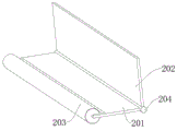
The inside material subassembly 3 position department that is close to of frame 1 is provided with the swager subassembly 2, the swager subassembly 2 is including fixing the cross brace 102 in frame 1 inboard, the upper surface of cross brace 102 flushes with the rectangle material hole 30231 downside, the swager subassembly 2 still includes the holding down plate 201 that rotates the setting in cross brace 102 top, holding down plate 201 upside is fixed with pivot 204, and pivot 204 is connected with frame 1 inboard rotation, pivot 204 upside is provided with trigger plate 202, and the contained angle is less than 90 degrees between trigger plate 202 and the holding down plate 201, holding down plate 201 keeps away from trigger plate 202 one side and is provided with the rectangle opening, and rotates in the rectangle opening and be provided with swager roller 203, door type fills can frame 301 upper portion and is provided with touch briquetting 3012 near trigger plate 202 one side, and the touch briquetting 3012 of moving down can drive trigger plate 202 rotation to drive holding down plate 201 rotation, the swager roller 203 that the cooperation set up compresses tightly the plastics composite bag.
Working principle: when the roller assembly 408 is used, firstly, the roller assembly 408 passes through roller cores, then, the roller assembly 408 is placed on two supports of the lock roller assembly 405, the set polygon column 4054 is inserted into the polygon groove 4084 and can press the touch bar 4085, the matched trapezoid block group 40821 and the frustum-shaped protrusions 40851 can drive the expansion plate 4082 to move outwards, the roller cores are fixed, a plastic composite bag to be wound passes through a gap between the material pressing roller 203 and the transverse supporting plate 102, then passes through the rectangular material passing holes 30231 on the rectangular retaining frame 3023, the plastic composite bag is wound on the roller cores, then, the driving motor 4071 is controlled to work, the belt 4072 and the belt 4073 are matched, the turntable 4051 on the lock roller assembly 405 is rotated, the polygon column 4054 is driven to rotate together, therefore, the roller assembly 408 and the roller cores are driven to rotate together, after the rolling of the plastic composite bag is achieved, the control cylinder 103 is contracted, the supporting frame 403 is driven to rotate, the first protrusion 1041 is arranged in the rotating process, when the supporting frame 403 rotates to the lower side, then, the first protrusion 1041 drives the first protrusion 10444 and the second protrusion 4062 to rotate, the second protrusion 4082 is driven to rotate, the second protrusion 4052 is driven to rotate, the sliding support 4052 is driven to rotate, the sliding rod 4052 is driven 4052, the sliding rod 4052 is driven to rotate, and the rolling rod 4052 is driven to rotate together, and the rolling rod 4052, and the rolling rod is rotated, and the rolling bag is rotated. When the supporting frame 403 contacts with the crank arm 305, the crank arm 305 is driven to rotate, so that the crank arm 305 and the locking abutting block 3034 on the material cutting tool rest 303 are separated, and under the action of the energy charging spring 3024, the material cutting tool rest 303 is driven to move downwards, the plastic composite bag is cut off by the arranged material cutting tool 3035, in the process of moving downwards the door-type energy charging frame 301, the contact pressing block 3012 is driven to move downwards and is matched with the trigger plate 202 on the material pressing assembly 2, the lower pressing plate 201 is driven to rotate, the plastic composite bag is pressed through the material pressing roller 203, the flatness of a cut of the plastic composite bag is ensured, the rolling assembly 4 can be driven to reset along with the extension of the air cylinder 103, in the process, the metal roller shaft 401 is driven to rotate, the door-type energy charging frame 301 is driven to move upwards by the first gear 3041 and the second gear 3042 which are matched with the first gear 3041 and the second gear 3032, and simultaneously, the material cutting tool rest 303 is driven to move upwards and reset under the action of the reset plate spring 3021, and the reset arm 305 is not pressed under the action of the reset plate pressing, so that the step plate spring 3053 is driven to rotate, and the lower end of the step pressing plate pressing tool rest 303 is locked.
Spatially relative terms, such as "above … …," "above … …," "upper surface at … …," "above," and the like, may be used herein for ease of description to describe one device or feature's spatial location relative to another device or feature as illustrated in the figures. It will be understood that the spatially relative terms are intended to encompass different orientations in use or operation in addition to the orientation depicted in the figures. For example, if the device in the figures is turned over, elements described as "above" or "over" other devices or structures would then be oriented "below" or "beneath" the other devices or structures. Thus, the exemplary term "above … …" may include both orientations of "above … …" and "below … …". The device may also be positioned in other different ways (rotated 90 degrees or at other orientations) and the spatially relative descriptors used herein interpreted accordingly.
It is noted that the terminology used herein is for the purpose of describing particular embodiments only and is not intended to be limiting of example embodiments in accordance with the present application. As used herein, the singular is also intended to include the plural unless the context clearly indicates otherwise, and furthermore, it is to be understood that the terms "comprises" and/or "comprising" when used in this specification are taken to specify the presence of stated features, steps, operations, devices, components, and/or combinations thereof.
It should be noted that the terms "first," "second," and the like in the description and claims of the present application and the above figures are used for distinguishing between similar objects and not necessarily for describing a particular sequential or chronological order. It is to be understood that the data so used may be interchanged where appropriate such that embodiments of the present application described herein may be capable of being practiced otherwise than as specifically illustrated and described herein. Furthermore, the terms "comprises," "comprising," and "having," and any variations thereof, are intended to cover a non-exclusive inclusion, such that a process, method, system, article, or apparatus that comprises a list of steps or elements is not necessarily limited to those steps or elements expressly listed but may include other steps or elements not expressly listed or inherent to such process, method, article, or apparatus.
The foregoing is only a preferred embodiment of the present invention, but the scope of the present invention is not limited thereto, and any person skilled in the art, who is within the scope of the present invention, should make equivalent substitutions or modifications according to the technical scheme of the present invention and the inventive concept thereof, and should be covered by the scope of the present invention.
Claims (9)
1. The utility model provides a coiling mechanism of plastics composite bag production line, includes frame (1), its characterized in that: a rolling component (4) is rotatably arranged on one side of the upper part of the machine base (1), an adjusting component for adjusting the angle of the rolling component (4) is arranged on the lower part of the inner side of the machine base (1), and a material breaking component (3) is arranged on the upper part of the machine base (1);
the utility model discloses a novel electric power machine, including frame (1) and support frame (403), frame (1) upper portion one end is provided with semicircle department (104), and semicircle department (104) position department coaxial rotation is provided with metal roller (401), metal roller (401) are close to frame (1) inboard department and are fixed with braced frame (403), braced frame (403) are U-shaped frame structure, braced frame (403) include horizontal plain portion (4033), and horizontal plain portion (4033) keep away from frame (1) one end and be provided with tilting portion (4032) that the slant leaned up, braced frame (403) both sides are close to tilting portion (4032) and horizontal plain portion (4033) symmetry and are provided with lock roller subassembly (405), lock roller subassembly (405) are including carousel (4051), braced frame (403) lateral wall is provided with the round hole that supplies carousel (4051) swivelling joint, carousel (4051) one end is provided with the slot, the slot is polygonal structure, and the slot interpolation is equipped with polygon prism (4054), polygon prism (4054) one end intermediate position department rotation is provided with pulling post (4052), it is provided with pulling roller (4052) to draw in the horizontal plain end (4033) to draw in the inside portion (4051), the inside pulling post (4052) is provided with the outside the jack (4051) and is provided with a horizontal plain end (4053) and is drawn in the outside the jack (4053), the upper part of the supporting frame (403) is provided with a driving component (407) for driving one of the turntables (4051) to rotate;
the utility model provides a take-off roller subassembly (404) is including sliding carriage (4041) of setting on horizontal flat part (4033), carriage (4041) are close to frame (1) one end and are provided with xarm (4043), and rotate on xarm (4043) and be provided with disc (4044), and the outer periphery of disc (4044) and semicircle arc portion (104) outer periphery contact, carriage (4041) lateral wall is provided with the sliding block, and horizontal flat part (4033) lateral wall is provided with bar slide (4034) along its length direction, the sliding block slides and sets up in bar slide (4034), bar slide (4034) are kept away from metal roller (401) one end inner wall and are fixed with third reset spring (40341), semicircle arc portion (104) lower part is provided with first bellying (1041), carriage (4041) are kept away from xarm (4043) one end and are provided with trigger lever (4042), be provided with second bellying (40421) on trigger lever (4042), be provided with bar slide (4052) along its length direction, bar slide (4052) are provided with trigger bar (4083) and insert bar passageway (5242).
2. The winding device of the plastic composite bag production line according to claim 1, wherein the adjusting assembly comprises a supporting frame (402) fixed at the lower part of the supporting frame (403), a hinging seat (101) is arranged at the inner side of the bottom of the machine base (1), an air cylinder (103) is hinged in the hinging seat (101), and the upper part of the air cylinder (103) is hinged with the lower part of the supporting frame (402).
3. The winding device of the plastic composite bag production line according to claim 2, wherein a handrail frame (4031) is arranged on one side of the supporting frame (403) far away from the metal roll shaft (401).
4. A winding device for a plastic composite bag production line according to claim 3, wherein a metal cover (406) is arranged on the upper portion of the supporting frame (403), the driving assembly (407) comprises a driving motor (4071) arranged at one end of the upper portion of the metal cover (406), a belt pulley (4072) is fixed on an output shaft of the driving motor (4071) through bolts, and the belt pulley (4072) and one of the rotating discs (4051) are sleeved with the same belt (4073).
5. The winding device of a plastic composite bag production line according to claim 4, wherein the same roll shaft assembly (408) is arranged between the two lock roll assemblies (405), the roll shaft assembly (408) comprises a hollow roll (4081), both ends of the hollow roll (4081) are respectively provided with a polygonal groove (4084) matched with a polygonal column (4054), the outer circumferential surface of the hollow roll (4081) is provided with an expansion assembly which is distributed in an annular mode at equal intervals, the expansion assembly comprises expansion battens (4082), strip-shaped holes (4083) for sliding of the expansion battens (4082) are formed in the outer circumferential surface of the hollow roll (4081), trapezoid block groups (40821) which are distributed symmetrically are formed in one side, close to the inner side of the hollow roll (4081), of the expansion battens (4082) are formed by a plurality of trapezoid blocks which are distributed in equal intervals, through holes are formed in the axial direction of the hollow roll (4081), two contact battens (4085) which are distributed symmetrically are arranged in the through holes, and two contact battens (4085) which are arranged symmetrically are arranged in the through holes, and two contact battens (4085) are arranged in the same place, and the two contact battens (4085) are close to the same place, and are located between the two contact battens (4085) and are located on the two contact battens.
6. The winding device of the plastic composite bag production line according to claim 5, wherein the material breaking assembly (3) comprises a retainer (302) arranged at the upper part of the inner side of the machine base (1), the retainer (302) comprises a rectangular retainer frame (3023), the top of the rectangular retainer frame (3023) is of an opening structure, two ends of the inner wall of the bottom of the rectangular retainer frame (3023) are respectively provided with a guide rod (3022) which is vertically arranged, the same cross beam (3021) is fixed at the upper part of the two guide rods (3022), the same gate-type filling frame (301) is arranged on the two guide rods (3022) in a sliding manner, the side wall of the rectangular retainer frame (3023) is provided with a rectangular material passing hole (30231) penetrating through the same, the lower part of the inner side of the rectangular retainer frame (3023) is provided with a positioning cutting tool rest (30233), the cutting tool rest (303) comprises a transverse plate (3031), the two ends of the transverse plate (3031) are respectively provided with a guide rod (3022), the two ends of the transverse plate (3031) are respectively provided with a transverse plate (3031), the two end faces (3034) of the guide rods (3032) can be respectively filled with a spring (3034) at the two ends of the transverse plate (3031), the utility model discloses a door type energy charging frame, including diaphragm (3031), frame (3031), metal roller (401) and frame (3031), diaphragm (3031) upper portion one side is provided with U-shaped frame (3033), and U-shaped frame (3033) keep away from diaphragm (3031) one side both sides position department all is provided with the locking of vertical setting and support piece (3034), frame (1) inboard both sides all are provided with the locking subassembly that is used for supporting locking and supports piece (3034), the both sides of frame (1) all are provided with link gear train (304) that drive door type energy charging frame (301) to rise along with metal roller (401) rotation.
7. The winding device of a plastic composite bag production line according to claim 6, wherein the locking assembly comprises a crank arm (305) rotatably arranged on the inner side of the machine base (1), a bevel part (3053) is arranged on one side, close to the rectangular holding frame (3023), of the upper part of the crank arm (305), a stepped groove is formed in the upper part of the bevel part (3053), a semicircular clamping groove (3052) is formed in the lower end of the crank arm (305), a reset plate spring (3051) is clamped in the semicircular clamping groove (3052), and the other end of the reset plate spring (3051) is fixedly connected with the inner wall of one side of the machine base (1).
8. The winding device of the plastic composite bag production line according to claim 7, wherein the linkage gear set (304) comprises a second gear (3042) fixedly connected with one end of a metal roller shaft (401), a first gear (3041) is rotatably arranged on the side wall of the base (1), the first gear (3041) is meshed with the second gear (3042), a tooth part (3011) is arranged at the position, close to the first gear (3041), of the side wall of the door type energy charging frame (301), the tooth part (3011) is meshed with the first gear (3041), and rectangular openings (30232) matched with the door type energy charging frame (301) are formed in two ends of the upper portion of the rectangular holding frame (3023).
9. The winding device of a plastic composite bag production line according to claim 8, wherein a pressing component (2) is arranged at a position, close to a breaking component (3), on the inner side of the machine base (1), the pressing component (2) comprises a transverse supporting plate (102) fixed on the inner side of the machine base (1), the upper surface of the transverse supporting plate (102) is flush with the lower side of a rectangular passing hole (30231), the pressing component (2) further comprises a lower pressing plate (201) rotatably arranged above the transverse supporting plate (102), a rotating shaft (204) is fixed on the upper side of the lower pressing plate (201), the rotating shaft (204) is rotatably connected with the inner side of the machine base (1), a trigger plate (202) is arranged on the upper side of the rotating shaft (204), an included angle between the trigger plate (202) and the lower pressing plate (201) is smaller than 90 degrees, a rectangular opening is arranged on one side, far away from the trigger plate (202), a pressing roller (203) is rotatably arranged in the rectangular opening, and a pressing block (3012) is arranged on the upper side, close to the trigger plate (202), of the door-shaped charging frame (301).
Priority Applications (1)
| Application Number | Priority Date | Filing Date | Title |
|---|---|---|---|
| CN202310246651.8A CN115924597B (en) | 2023-03-15 | 2023-03-15 | Coiling mechanism of plastics composite bag production line |
Applications Claiming Priority (1)
| Application Number | Priority Date | Filing Date | Title |
|---|---|---|---|
| CN202310246651.8A CN115924597B (en) | 2023-03-15 | 2023-03-15 | Coiling mechanism of plastics composite bag production line |
Publications (2)
| Publication Number | Publication Date |
|---|---|
| CN115924597A CN115924597A (en) | 2023-04-07 |
| CN115924597B true CN115924597B (en) | 2023-05-16 |
Family
ID=85825600
Family Applications (1)
| Application Number | Title | Priority Date | Filing Date |
|---|---|---|---|
| CN202310246651.8A Active CN115924597B (en) | 2023-03-15 | 2023-03-15 | Coiling mechanism of plastics composite bag production line |
Country Status (1)
| Country | Link |
|---|---|
| CN (1) | CN115924597B (en) |
Family Cites Families (6)
| Publication number | Priority date | Publication date | Assignee | Title |
|---|---|---|---|---|
| CN103754677B (en) * | 2014-01-22 | 2017-08-18 | 潍坊兴信工程项目管理有限公司 | Polybag automatic winding lap changing apparatus |
| US20160280500A1 (en) * | 2015-03-23 | 2016-09-29 | Cosmo Machinery Co., Ltd. | Slit line making machenism for film roll/bag-on-a-roll making machine |
| CN213864564U (en) * | 2020-11-05 | 2021-08-03 | 杭州申嘉纺织有限公司 | Cloth coiling mechanism of weaving machine |
| CN215797345U (en) * | 2021-01-19 | 2022-02-11 | 江苏盛鸿电工器材有限公司 | Special rolling equipment of alkali-free glass fiber cloth |
| CN215325914U (en) * | 2021-05-28 | 2021-12-28 | 河南银河铝业有限公司 | Novel telescopic coiling mechanism is used in processing of aluminium book |
| CN114261814A (en) * | 2021-12-29 | 2022-04-01 | 福建福融新材料有限公司 | Coiling mechanism is used in polyethylene plastic film production |
-
2023
- 2023-03-15 CN CN202310246651.8A patent/CN115924597B/en active Active
Also Published As
| Publication number | Publication date |
|---|---|
| CN115924597A (en) | 2023-04-07 |
Similar Documents
| Publication | Publication Date | Title |
|---|---|---|
| CN110723348B (en) | Two-sided pad pasting device | |
| CN109773888B (en) | Continuous die-cutting and tidying equipment for polaroid and production process thereof | |
| CN113787147B (en) | Lead frame conveying and blanking device | |
| CN115924597B (en) | Coiling mechanism of plastics composite bag production line | |
| CN212602070U (en) | Finishing device is cut with finished product to papermaking production | |
| CN116119417B (en) | Electroplating superconducting strip winding equipment and winding method | |
| CN112606050A (en) | Corrugated board re-preparation processing method | |
| CN115255451A (en) | Pressing and drilling device for electric spindle production | |
| CN210791237U (en) | Automatic die cutting equipment capable of automatically removing waste materials | |
| CN220362633U (en) | Film dividing and cutting machine capable of automatically collecting and recycling waste materials | |
| CN213111742U (en) | Rim charge coiling machine for slitting machine | |
| CN217675951U (en) | Full-automatic cutting machine of sticky tape | |
| CN219791839U (en) | Winding machine for producing protective film | |
| CN219114821U (en) | Door and window frame section bar pad pasting equipment | |
| CN219006173U (en) | Wiping cloth slitting device | |
| CN215905516U (en) | Aluminum strip slitter edge collection device | |
| CN220055655U (en) | Plastic sheet cutting and winding device | |
| CN216332975U (en) | Silicon steel sheet adhesive tape winding machine | |
| CN116477399B (en) | Base cloth conveying device for polishing pad production line and working method | |
| CN212810186U (en) | Outer belt wrapping machine for producing printer relay | |
| CN215032695U (en) | Punch forming equipment for vegetable can | |
| CN212045052U (en) | Adhesive tape splitting machine | |
| CN218809289U (en) | Automatic unloading mechanism of electronic tags | |
| CN219748187U (en) | Biological material extrusion processing mechanism with irregular appearance | |
| CN220826082U (en) | Plastic carrier tape slitting equipment |
Legal Events
| Date | Code | Title | Description |
|---|---|---|---|
| PB01 | Publication | ||
| PB01 | Publication | ||
| SE01 | Entry into force of request for substantive examination | ||
| SE01 | Entry into force of request for substantive examination | ||
| GR01 | Patent grant | ||
| GR01 | Patent grant |