CN109773888B - Continuous die-cutting and tidying equipment for polaroid and production process thereof - Google Patents
Continuous die-cutting and tidying equipment for polaroid and production process thereof Download PDFInfo
- Publication number
- CN109773888B CN109773888B CN201910086384.6A CN201910086384A CN109773888B CN 109773888 B CN109773888 B CN 109773888B CN 201910086384 A CN201910086384 A CN 201910086384A CN 109773888 B CN109773888 B CN 109773888B
- Authority
- CN
- China
- Prior art keywords
- plate
- take
- polaroid
- die
- cutting
- Prior art date
- Legal status (The legal status is an assumption and is not a legal conclusion. Google has not performed a legal analysis and makes no representation as to the accuracy of the status listed.)
- Active
Links
Images


Abstract
The invention relates to the technical field of polaroid preparation, in particular to continuous die-cutting and tidying equipment for a polaroid and a production process thereof, and the equipment comprises a controller, a processing table, an unreeling mechanism, a die-cutting mechanism, an unloading mechanism and a tidying mechanism which are sequentially arranged on the processing table along a straight line, wherein the interval distance between the unloading mechanism and the die-cutting mechanism is 2.5-3.5 cm, the downstream end of the processing table is provided with an unloading notch groove, the tidying mechanism comprises a take-over plate arranged right below the unloading notch groove, a containing assembly arranged at the side of the take-over plate and a material stirring assembly arranged above the take-over plate, a lifting assembly used for driving the take-over plate to vertically move into the unloading notch groove is arranged below the take-over plate, and a position sensor electrically connected with the controller is arranged at one side in the unloading notch groove Full-automatic cross cutting links up with regular full automatization, has greatly improved the production efficiency of polaroid.
Description
Technical Field
The invention relates to the technical field of polarizer preparation, in particular to continuous die-cutting and integrating equipment for a polarizer and a production process thereof.
Background
The polaroids are all called as polaroids, the imaging of the liquid crystal display is dependent on polarized light, all liquid crystals have front and rear polaroids which are tightly attached to liquid crystal glass to form the liquid crystal sheet with the total thickness of about 1mm, and if any polaroid is omitted, the liquid crystal sheet cannot display images.
When the polaroid cuts, at first need lapping polaroid (coiled material) to place on the board, then it unreels to implement it, in-process pulling polaroid at unreeling stretches out the removal, cutting knife on the board cuts into a plurality of monolithic polaroids (sheet) with the coiled material, generally adopt the cross cutting mode, current equipment all can be automatic carries out the cross cutting to the polaroid, but all do not possess the polaroid after cutting and carry out regular collection, because this type of polaroid is cut the quantity after huge, the specification is smaller again simultaneously, and thickness is thin, so general manual work is put in order, need very careful operation, so the operation degree of difficulty is big, it is consuming time high, very influence work efficiency.
Disclosure of Invention
In view of the defects of the prior art, an object of the present invention is to provide a continuous die-cutting and integrating apparatus for polarizers.
The invention also aims to provide a production process of the continuous die-cutting and tidying equipment for the polaroid.
The invention discloses continuous die cutting and tidying equipment for polaroids, which comprises a controller, a processing table, an unreeling mechanism, a die cutting mechanism, an unloading mechanism and a tidying mechanism, wherein the unreeling mechanism, the die cutting mechanism, the unloading mechanism and the tidying mechanism are sequentially arranged on the processing table along a straight line, the interval distance between the unloading mechanism and the die cutting mechanism is 2.5-3.5 cm, an unloading notch groove is formed in the downstream end of the processing table, the tidying mechanism comprises a take-over plate arranged right below the unloading notch groove, an accommodating assembly arranged on the side of the take-over plate and a material poking assembly arranged above the take-over plate, a lifting assembly used for driving the take-over plate to vertically move into the unloading notch groove is arranged below the take-over plate, and a position sensor electrically connected with the controller is arranged on one.
Furthermore, the take-over plate is of a long strip structure, the two ends of the wide edge of the take-over plate correspond to the front side and the rear side of the processing table, the lifting mechanism comprises a lifting air rod, a piston rod of the lifting air rod is connected with the middle section area of the bottom of the take-over plate, the storage assembly comprises a storage bin, one side of the storage bin corresponding to the take-over plate is provided with a plurality of guide grooves capable of allowing the take-over plate to vertically move, the piston rod of the lifting air rod is in a retraction state, the upper surface of the take-over plate is flush with the upper surface of the storage bin, and a gap which is not more than 0.5mm is reserved on one side close to.
Further, the collecting storage is vertical, and a plurality of feeding cavities that replace the equal interval distribution of long limit direction of board along taking over are seted up at its top, all run through the bottom of collecting storage at the bottom of the chamber of every feeding cavity, the storage assembly still includes electric putter and a plurality of bearing piece, all bearing pieces are the level respectively and locate a feeding cavity in, the vertical clearance fit of all internal faces of bearing piece and feeding cavity, the bottom of collecting storage is equipped with the connecting plate, be connected with all bearing pieces one by one through a plurality of gangbars on the connecting plate respectively, electric putter is the inversion and installs outside one side of collecting storage, and its output pole is connected with the connecting plate transmission.
Further, the dorsal part that the collecting chamber kept away from and connect the board is provided with the separation door plant that can upwards stimulate, the bottom and the collecting chamber joint cooperation that hinder the door plant, the storage assembly still includes the guide holder, the motor of unloading and the electric jar of unloading, the electric jar of unloading is the level setting, the guide holder is installed on the output of the electric jar of unloading, and it can directly keep away from and connect the board through the electric jar drive of unloading, the guide holder is U type structure, the front side bottom of collecting chamber is equipped with the chimb, this chimb articulates in the opening of guide holder through the pivot, the motor of unloading is installed in the outside of guide holder and is connected with the pivot transmission.
Furthermore, the material shifting assembly comprises a U-shaped frame, a micro air rod and a material shifting motor, sliding rails are arranged on the front side and the rear side of the processing table respectively, the sliding rails are located below the processing table, the extending direction of the sliding rails is consistent with the unreeling direction of the unreeling mechanism, a sliding block capable of moving horizontally is arranged in each sliding rail, each sliding block is of a U-shaped structure with an upward opening, two ends of the opening of the U-shaped frame are respectively arranged in the opening of one sliding block through a reset spring and capable of moving vertically, a motor base is arranged outside one sliding block, a cam motor is arranged on each motor base, a contact plate is arranged at one end, corresponding to the cam motor, of the U-shaped frame, a micro cam is arranged above the contact plate, the cam motor is coaxially connected with the micro cam in a transmission mode, the micro cam is connected with the upper surface of the contact plate in a transmission mode, And it has the stirring pole to be close to its roof department articulated, stirs the material motor and installs in the outside of U type frame and be connected with stirring pole transmission, through a crossbeam board fixed connection between two sliders, and the one side of accomodating the subassembly is kept away from to the crossbeam board is located to the fine motion gas pole, and the piston rod and the crossbeam board transmission of fine motion gas pole are connected.
Furthermore, the discharging mechanism comprises a pressing plate arranged right above the discharging notch, a thin cylinder used for driving the pressing plate to move vertically is arranged above the pressing plate, a plurality of pressing heads arranged at equal intervals are arranged on the lower surface of the pressing plate, and the arrangement direction of all the pressing heads is consistent with that of all the bearing sheets.
Further, the die cutting mechanism comprises a die cutting tool and a die cutting air cylinder, wherein the die cutting tool is horizontal and can be vertically and movably arranged through the die cutting air cylinder.
Further, unwinding mechanism includes that the inflatable shaft, tension roller set and the carry over pinch rolls that follow a straight line order set gradually, and the carry over pinch rolls passes through the back timber support and sets up in processing platform top, installs on the back timber support to be used for driving the carry over pinch rolls around self axis pivoted servo motor, and manual lead screw regulating part is installed to the side of processing platform, and the one end and the manual lead screw regulating part transmission fit of back timber support to through its can vertical activity setting.
Further, servo motor and cross cutting cylinder all with controller electric connection, be equipped with two symmetrical side limit clamp plates between cross cutting tool and the carry over pinch rolls, every side limit clamp plate is L type structure to its minor face end is the side that the level is located processing bench top, and every side limit clamp plate is close one end and the articulated cooperation of processing bench of cross cutting tool, and the edge department articulates in the right angle of side limit clamp plate has a plurality of compressing tightly the piece wheel.
The production process of the continuous die-cutting and tidying equipment for the polaroid comprises the following steps:
step one, performing step-by-step unwinding on a coiled polaroid by an unwinding mechanism, forming pressing crease-resistant limiting on two sides of the coiled polaroid by two side limiting pressing plates in the process, and finally conveying the unwinding end to the position right below a die cutting mechanism in a step-by-step manner;
step two, the die cutting mechanism starts to work, die cutting is carried out on the polaroid right below the die cutting mechanism, after the die cutting is finished, the unreeling mechanism step-by-step conveys the die-cut part of the polaroid to an unloading notch area, and the area is filled by a replacing plate at the moment, so that the conveyed polaroid is supported;
thirdly, the discharging mechanism presses down the independent polaroids die-cut in the second step to enable the independent polaroids to be completely separated from the whole polaroids and to fall onto the take-over board completely, the take-over board descends through the lifting assembly immediately, and the upper surfaces of the descended take-over boards are flush with the upper surface of the storage bin;
after the replacing plate descends to a set position, the material shifting assembly moves to the position above the replacing plate, and a plurality of independent polaroids on the upper surface of the material shifting assembly are delivered to the storage bin in a friction contact mode and then quickly reset so that the replacing plate can ascend and reset to the discharging notch groove;
after all the polaroids on the replacing plate reach the storage bin in the third step, the bearing sheet corresponding to each independent polaroid is slightly lowered by virtue of the electric push rod, so that the upper surface of one polaroid positioned at the uppermost part of a certain bearing sheet is always flush with the upper surface of the storage bin, and therefore the subsequent polaroid stacking work is facilitated, and meanwhile, the rest polaroids on the bearing sheet are positioned in the feeding concave cavity in a stacking posture;
and step six, after the take-over plate in step four rises and resets to the inside of the discharging notch groove, and after the take-over plate is detected by the position sensor, the take-over plate transmits an electric signal to the controller, and the controller instructs the servo motor to work, so that the traction roller starts to pull the subsequent polaroid, and the purposes of circular traction, die cutting and regular discharging are achieved.
Has the advantages that: the invention relates to a continuous die-cutting and tidying device for polaroids, which is characterized in that coiled polaroids are subjected to stepping unreeling by an unreeling mechanism, two sides of the coiled polaroids form crease-resistant limiting by two side limiting press plates in the process, finally, an unreeling end is conveyed to the position under a die-cutting mechanism in a stepping mode, then, the die-cutting mechanism starts to work, die-cutting is carried out on the polaroids under the die-cutting mechanism, after the die-cutting is finished, the unreeling mechanism conveys the die-cut parts of the polaroids to an unloading notch area in a stepping mode, the area is filled by a replacing plate at the moment, so that the conveyed polaroids are supported, the independent polaroids of an unloading mechanism are subjected to pressing down, the polaroids are completely separated from the whole polaroids and fall onto the replacing plate completely, then, the replacing plate descends through a lifting assembly, the upper surfaces of the descended replacing plate are flush with the upper surfaces of a storage bin, and then a, and a plurality of independent polaroids on the upper surface of the support plate are delivered to the storage bin in a friction contact mode and then reset rapidly, so that the take-over plate rises and resets to the discharging notch groove, after all the polaroids reach the storage bin, the support plate corresponding to each independent polaroid descends slightly by virtue of the electric push rod, the upper surface of the uppermost polaroid of a certain support plate is always flush with the upper surface of the storage bin, so that the subsequent polaroid stacking work is facilitated, meanwhile, the rest polaroids on the support plate are positioned in the feeding concave cavity in a stacking posture, after the take-over plate rises and resets to the discharging notch groove, and the position sensor detects the upper surface of the support plate, the controller transmits an electric signal to the controller, and the controller instructs the servo motor to work, so that the traction roller starts to pull the subsequent polaroids, and therefore, the aim of cyclic traction is achieved, The automatic collecting device can automatically collect the cut polaroids in a unified way instead of manual collection, so that the working efficiency is greatly improved, the automatic degree is high, the efficiency is improved by 10-15 times compared with manual collection, and more than 70% of manual work can be saved;
the production process is ingenious in design, the steps are connected in a coherent mode, unwinding, full-automatic die cutting and regular full automation of the polaroid are achieved, and production efficiency of the polaroid is greatly improved.
Drawings
The accompanying drawings, which are included to provide a further understanding of the application and are incorporated in and constitute a part of this application, illustrate embodiment(s) of the application and together with the description serve to explain the application and not to limit the application. In the drawings:
FIG. 1 is a first perspective view of the present invention;
FIG. 2 is a first schematic plan view of the present invention;
FIG. 3 is a partial perspective view of the first embodiment of the present invention;
FIG. 4 is a second schematic plan view of the present invention;
FIG. 5 is a partial perspective view of the second embodiment of the present invention;
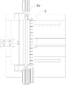
FIG. 6 is an enlarged view taken at A in FIG. 5;
FIG. 7 is a third schematic view of a partial perspective structure of the present invention;
FIG. 8 is a fourth schematic partial perspective view of the present invention;
FIG. 9 is a schematic diagram of a partial perspective structure according to the present invention;
FIG. 10 is an enlarged view of FIG. 9 at B;
FIG. 11 is a third schematic plan view of the present invention;
description of reference numerals: a processing table 1, a discharge notch 1a and a position sensor 1 b.
A take-over plate 2 and an air lifting rod 2 a.
The feed bin 3, feed cavity 3a, electric putter 3b, bearing piece 3c, connecting plate 3 d.
A barrier door panel 4.
A pressing plate 7, a thin cylinder 7a and a pressing head 7 b.
The device comprises an air expansion shaft 8, a tension roller group 8a, a traction roller 8b, a top beam support 8c, a servo motor 8d and a manual lead screw adjusting piece 8 r.
A side limit pressing plate 9 and a pressing plate wheel 9 a.
A die cutting mechanism 10.
Detailed Description
In the following description, for purposes of explanation, numerous implementation details are set forth in order to provide a thorough understanding of the various embodiments of the present invention. It should be understood, however, that these implementation details are not to be interpreted as limiting the invention. That is, in some embodiments of the invention, such implementation details are not necessary. In addition, some conventional structures and components are shown in simplified schematic form in the drawings.
In addition, in the present invention, the descriptions related to "first", "second", etc. are only used for description purposes, do not refer to specific meanings in sequence or order, and do not limit the present invention, and they are only used for distinguishing components or operations described in the same technical terms, and they are not interpreted as indicating or implying relative importance or implicit to the number of technical features indicated. Thus, a feature defined as "first" or "second" may explicitly or implicitly include at least one such feature. In addition, the technical solutions in the embodiments may be combined with each other, but must be realized by those skilled in the art, and when the technical solutions are contradictory or cannot be realized, such a combination should not be considered to exist, and is not within the protection scope of the present invention.
Example 1
Referring to fig. 1 to 11, the continuous die-cutting and tidying device for the polarizer comprises a controller, a processing table 1, an unreeling mechanism, a die-cutting mechanism 10, an unloading mechanism and a tidying mechanism, wherein the unreeling mechanism, the die-cutting mechanism 10, the unloading mechanism and the tidying mechanism are sequentially arranged on the processing table 1 along a straight line, the interval distance between the unloading mechanism and the die-cutting mechanism 10 is 2.5 cm-3.5 cm, a discharging lacking groove 1a is formed in the downstream end of the processing table 1, the tidying mechanism comprises a replacing plate 2 installed under the discharging lacking groove 1a, an accommodating assembly arranged beside the replacing plate 2 and a material shifting assembly arranged above the replacing plate 2, a lifting assembly used for driving the replacing plate 2 to vertically move into the discharging lacking groove 1a is arranged under the replacing plate 2, and a position sensor 1b electrically connected with the controller is installed on one side in the discharging lacking groove 1 a.
The replacing plate 2 is of a long strip structure, the two ends of the wide edge of the replacing plate 2 correspond to the front side and the rear side of the processing table 1, the lifting mechanism comprises a lifting air rod 2a, a piston rod of the lifting air rod 2a is connected with the middle section area of the bottom of the replacing plate 2, the containing assembly comprises a containing bin 3, one side of the containing bin 3 corresponding to the replacing plate 2 is provided with a plurality of guide grooves capable of enabling the replacing plate 2 to vertically move, the piston rod of the lifting air rod 2a is in a retraction state, the upper surface of the replacing plate 2 is flush with the upper surface of the containing bin 3, and a gap which is not more than 0.5mm is reserved on one side close to the upper surface of the replacing plate 2 and the; after the polaroid is unreeled and is pulled to a position right below the die cutting mechanism 10, the polaroid is subjected to die cutting by the die cutting mechanism; after the die cutting is finished, the polaroid is continuously pulled, the die-cut part of the front section is pulled to be right above the take-over plate 2, namely the discharging notch 1a, then the discharging mechanism starts to press down the die-cut multiple fragmentary polaroids, and meanwhile, the upper surface of the take-over plate 2 is flush with the upper surface of the processing table 1, the fragmentary polaroids are separated from the whole polaroid after being pressed down by the discharging mechanism and are supported by the take-over plate 2, then the output rod of the lifting air rod 2a retracts, so that the take-over plate 2 descends in a short distance, the descending stroke is kept in a range of 3-4cm, the take-over plate 2 is flush with the upper surface of the storage bin 3, and therefore the subsequent material shifting assembly can move the plurality of fragmentary take-over polaroids on the take-over plate 2 to the storage bin 3; with this purpose that reaches the purpose of unloading, take over board 2 simultaneously and take over when 3 close one side clearance fit makes the polarisation carry out transition between the two and move, can not produce the hindrance.
The collecting bin 3 is vertical, a plurality of feeding cavities 3a distributed at equal intervals along the long edge direction of the take-over plate 2 are formed in the top of the collecting bin, the bottom of each feeding cavity 3a penetrates through the bottom of the collecting bin 3, the collecting assembly further comprises an electric push rod 3b and a plurality of bearing sheets 3c, all the bearing sheets 3c are horizontally arranged in one feeding cavity 3a respectively, the bearing sheets 3c are vertically and movably matched with all inner wall surfaces of the feeding cavities 3a, a connecting plate 3d is arranged at the bottom of the collecting bin 3, the connecting plate 3d is connected with all the bearing sheets 3c one by one through a plurality of linkage rods, the electric push rod 3b is arranged outside one side of the collecting bin 3 in an inverted mode, and an output rod of the electric push rod is in transmission connection with the connecting plate 3 d; in the first embodiment, after the plurality of fragmentary polarizers reach the storage bin 3, and in the process, the plurality of fragmentary polarizers directly move to the supporting sheet 3 c; phase change shows that the arrangement sequence of all the bearing sheets 3c is consistent with the number and the arrangement sequence of the plurality of the chopped polaroids in the pre-mould cutting mode, so that each bearing sheet 3c is used for bearing one polaroid; and remark, under the initial posture of the bearing sheet 3c, the upper surface of the bearing sheet is flush with the upper surface of the storage bin 3, when a polaroid is conveyed, the bearing sheet 3c descends slightly under the action of the electric push rod 3b, the descending stroke is similar to the thickness of the polaroid, each polaroid can be stacked, and meanwhile, the descending of the bearing sheet 3c occurs in the feeding cavity 3a, so that the polaroids stacked at the top of the bearing sheet are all positioned in the feeding cavity 3a, the wrapping type limiting is achieved, and the stability of the stacking is ensured.
The back side of the storage bin 3, which is far away from the take-up plate 2, is provided with a separation door plate 4 capable of being pulled upwards, the bottom of the separation door plate 4 is in clamping fit with the storage bin 3, the storage assembly further comprises a guide seat 5, a discharging motor 5a and a discharging electric cylinder 5b, the discharging electric cylinder 5b is horizontally arranged, the guide seat 5 is installed at the output end of the discharging electric cylinder 5b and can be directly far away from the take-up plate 2 under the driving of the discharging electric cylinder 5b, the guide seat 5 is of a U-shaped structure, the bottom of the front side of the storage bin 3 is provided with a convex edge 5c, the convex edge 5c is hinged in an opening of the guide seat 5 through a rotating shaft, and the discharging motor 5a is installed outside the guide seat 5 and; when all feeding cavities 3a in the storage bin 3 reach full load, the discharging electric cylinder 5b drives the guide seat 5 to drive the storage bin 3 to move, the direction is towards the direction far away from the take-over plate 2, after the discharging electric cylinder moves to a set position, the discharging motor 5a starts to work, the convex edge 5c is driven to drive the storage bin 3 to rotate, the angle is 90 degrees, the rotating posture is that the separation door plate 4 is located above, the separation door plate 4 can be opened manually at the moment, stacked polaroids in all feeding cavities 3a are taken out, and all polaroids at the moment can be orderly stacked one by one.
The material shifting assembly comprises a U-shaped frame 6, a micro-motion air rod 6a and a material shifting motor 6b, the front side and the rear side of the processing table 1 are respectively provided with a slide rail 6c, the slide rails 6c are positioned below the processing table 1, the extending direction of the slide rails 6c is consistent with the unreeling direction of the unreeling mechanism, each slide rail 6c is internally provided with a slide block 6d capable of moving horizontally, each slide block 6d is of a U-shaped structure with an upward opening, two ends of the opening position of the U-shaped frame 6 are respectively arranged in the opening of one slide block 6d through a reset spring 6e and capable of moving vertically, a motor base is arranged outside one slide block 6d, the motor base is provided with a cam motor 6f, one end of the U-shaped frame 6 corresponding to the cam motor 6f is provided with a contact plate 6g, a cam 6t is arranged above the contact plate 6g, the cam motor 6f is coaxially connected with the micro-motion cam 6, the micro-motion cam 6t is in transmission connection with the upper surface of the contact plate 6g, a material stirring rod 6r is hinged in an opening of the U-shaped frame 6 and close to the top wall of the U-shaped frame, a material stirring motor 6b is installed outside the U-shaped frame 6 and is in transmission connection with the material stirring rod 6r, the two sliding blocks 6d are fixedly connected through a cross beam plate 6q, the micro-motion air rod 6a is arranged on one side, far away from the containing assembly, of the cross beam plate 6q, and a piston rod of the micro-motion air rod 6a is in transmission connection with the cross beam plate 6 q; after the plurality of the fragmentary polaroids are received on the succession plate 2 in the embodiment 1 and the succession plate 2 is descended to the set position, the micro-motion air rod 6a works rapidly, so that the U-shaped frame 6 is displaced to be right above the succession plate 2, the material shifting motor 6b starts to work, the micro-motion air rod is dependent on the rotation of the micro-motion cam 6t, the convex part of the micro-motion cam 6t is abutted to the contact plate 6g, the contact plate 6g is promoted to drive the U-shaped frame 6 to descend, the material shifting rod 6r descends in a micro-motion mode, the purpose of the micro-motion air rod is contacted with the upper surfaces of the fragmentary polaroids on the succession plate 2, meanwhile, the material shifting motor 6b starts to work, the material shifting rod 6r is promoted to rotate, due to the friction force, the fragmentary polaroids are promoted to be drawn to the upper surface of the storage bin 3, so as to achieve the unloading, the rapid resetting is carried out after the unloading is finished, the succession plate 2 is reset by the lifting air rod 2a, achieving the purpose of being flush with the upper surface of the processing table 1.
The discharging mechanism comprises a pressing plate 7 arranged right above the discharging notch 1a, a thin cylinder 7a used for driving the pressing plate 7 to move vertically is arranged above the pressing plate 7, a plurality of pressing heads 7b arranged at equal intervals are arranged on the lower surface of the pressing plate 7, and the arrangement direction of all the pressing heads 7b is consistent with that of all the bearing sheets 3 c; after the polaroid is unreeled and is pulled to a position right below the die cutting mechanism 10, the polaroid is subjected to die cutting by the polaroid; after the die cutting is finished, the polaroid continues to be pulled, the die-cut part of the front section is pulled right above the succession plate 2, namely the discharging notch 1a is formed, the succession plate 2 is positioned in the discharging notch 1a at the moment, then the thin cylinder 7a works to promote the pressure plate 7 to descend, all pressure heads 7b are in one-to-one corresponding contact with a plurality of fragmentary polaroids subjected to the die cutting in advance, due to the contact force, the plurality of fragmentary polaroids are completely separated from the whole polaroid, the succession plate 2 is used for bearing, and finally regular discharging is achieved.
The die cutting mechanism 10 comprises a die cutting tool and a die cutting cylinder, wherein the die cutting tool is horizontal and can be vertically and movably arranged through the die cutting cylinder; the die cutting cylinder drives the die cutting tool to vertically move to contact the polaroid, so that the purpose of cutting is achieved.
The unwinding mechanism comprises an air expansion shaft 8, a tension roller set 8a and a traction roller 8b which are sequentially arranged along a straight line, the traction roller 8b is arranged above the processing table 1 through a top beam support 8c, a servo motor 8d for driving the traction roller 8b to rotate around the axis of the traction roller 8b is arranged on the top beam support 8c, a manual screw rod adjusting piece 8r is arranged beside the processing table 1, and one end of the top beam support 8c is in transmission fit with the manual screw rod adjusting piece 8r and can be vertically and movably arranged through the manual screw rod adjusting piece 8 r; the air expansion shaft 8 is used for discharging the coiled polaroid; the tension roller group 8a ensures that the polaroid is kept in a tight state in discharging, and the collapse is prevented, the top beam support 8c is lifted or lowered by the manual shell through the manual lead screw adjusting piece 8r, so that the traction roller 8b can be well contacted with the polaroid part outside the tension roller group 8a, and the purpose of traction feeding is achieved; the servo motor 8d rotates to rotate the traction roller 8b, so that friction is formed between the traction roller and the polaroid, and the purpose of traction is achieved.
The servo motor 8d and the die cutting cylinder are electrically connected with the controller, two symmetrical side limit pressing plates 9 are arranged between the die cutting tool and the traction roller 8b, each side limit pressing plate 9 is of an L-shaped structure, the short edge end of each side limit pressing plate is a side edge horizontally positioned at the top of the processing table 1, one end of each side limit pressing plate 9 close to the die cutting tool is hinged and matched with the processing table 1, and a plurality of pressing plate wheels 9a are hinged at the inner side of the right angle of each side limit pressing plate 9; when the replacing plate 2 is positioned in the discharging notch 1a and is detected by the position sensor 1b, the servo motor 8d starts to drive to enable the polaroid to be dragged and unreeled, after the dragging working step is completed, the die cutting cylinder starts to carry out die cutting work through the die cutting tool, and finally the servo motor 8d drags a plurality of die-cut polaroids to the discharging notch 1a area again to achieve the discharging purpose; meanwhile, the arrangement of the side limiting pressing plates 9 enables the polarizer which is unwound and drawn to be stably positioned between the two side limiting pressing plates 9 to limit the polarizer, and the side-limited part of the polarizer cannot be folded by the arrangement of the pressing sheet wheel 9 a; meanwhile, the side limit pressing plate 9 has the structural characteristic of being capable of being turned over, so that the material guiding work of the polaroid is facilitated.
Example 2
The production process of the continuous die-cutting and tidying equipment for the polaroid, disclosed by embodiment 1, comprises the following steps of:
step one, performing step-by-step unwinding on a coiled polaroid by an unwinding mechanism, forming pressing crease-resistant limiting on two sides of the coiled polaroid by two side limiting pressing plates 9 in the process, and finally conveying the unwinding end to the position right below a die cutting mechanism 10 in a step-by-step manner;
step two, the die cutting mechanism 10 starts to work, die cutting is carried out on the polaroid right below the die cutting mechanism, after the die cutting is finished, the unreeling mechanism carries out step-by-step conveying on the die-cut part of the polaroid to the area of the unloading notch 1a, and the area is filled by the replacing plate 2 at the moment, so that the conveyed polaroid is supported;
thirdly, the discharging mechanism presses down the independent polaroids die-cut in the second step to enable the independent polaroids to be completely separated from the whole polaroid and completely fall onto the take-over plate 2, the take-over plate 2 descends through the lifting assembly, and the upper surface of the descending take-over plate 2 is flush with the upper surface of the storage bin 3;
step four, after the take-over plate 2 descends to a set position, the material shifting assembly moves to the position above the take-over plate 2, and a plurality of independent polaroids on the upper surface of the take-over plate are delivered to the storage bin 3 in a friction contact mode and then reset rapidly, so that the take-over plate 2 rises and resets to the discharging notch 1 a;
after all the polaroids on the succession plate 2 reach the storage bin 3 in the third step, the bearing sheet 3c corresponding to each independent polaroid slightly descends by virtue of the electric push rod 3b, so that the upper surface of the uppermost polaroid of a certain bearing sheet 3c is always flush with the upper surface of the storage bin 3, the subsequent polaroid stacking work is facilitated, and meanwhile, the rest polaroids on the bearing sheets 3c are positioned in the feeding cavity 3a in a stacking posture;
and step six, after the succession plate 2 in step four rises and resets to the inside of the discharging notch 1a, and after the succession plate is detected by the position sensor 1b, the succession plate transmits an electric signal to the controller, and the controller instructs the servo motor 8d to work, so that the traction roller 8b starts to pull the subsequent polaroid, and accordingly, cyclic traction, die cutting and regular discharging are achieved.
The working principle is as follows: the coiled polaroid is unreeled step by an unreeling mechanism, in the process, two sides of the coiled polaroid form pressing crease-resistant limit by two side limit pressing plates 9, finally, the unreeling end is transported to the position under a die cutting mechanism 10 step by step, then the die cutting mechanism 10 starts working, die cutting is carried out on the polaroid under the die cutting mechanism, after the die cutting is finished, the unreeling mechanism transports the die-cut part of the polaroid to the area of a discharging notch 1a step by step, and the area is filled by a replacing plate 2 at the moment, so as to support the transported polaroid, the discharging mechanism presses down the independent polaroids to ensure that the independent polaroids are completely separated from the whole polaroid and completely fall onto the replacing plate 2, then the replacing plate 2 descends by a lifting assembly, the upper surface of the descending replacing plate 2 is flush with the upper surface of a receiving bin 3, and then a material shifting assembly advances to the position above the replacing plate 2, and a plurality of independent polaroids on the upper surface are delivered to the containing bin 3 in a friction contact mode, and then reset rapidly, so that the replacing plate 2 is lifted and reset to the discharging notch 1a, after all the polaroids reach the containing bin 3, the supporting sheet 3c corresponding to each independent polaroid is descended slightly by virtue of the electric push rod 3b, so that the upper surface of the polaroid at the top of a certain supporting sheet 3c is always flush with the upper surface of the containing bin 3, thereby facilitating the subsequent stacking work of the polaroids, meanwhile, the other polaroids on the supporting sheet 3c are positioned in the feeding cavity 3a in a stacking posture, after the replacing plate 2 is lifted and reset to the discharging notch 1a and detected by the position sensor 1b, the controller transmits an electric signal to the controller, and the controller instructs the servo motor 8d to work, so that the traction roller 8b starts to pull the subsequent polaroid, thereby achieving the circulating traction, die cutting and regular unloading work.
The above description is only an embodiment of the present invention, and is not intended to limit the present invention. Various modifications and alterations to this invention will become apparent to those skilled in the art. Any modification, equivalent replacement, improvement, etc. made within the spirit and principle of the present invention should be included in the scope of the claims of the present invention.
Claims (9)
1. The utility model provides a continuous cross cutting of polaroid gui zhi qu zhen equipment which characterized in that: the automatic feeding device comprises a controller, a processing table (1), an unreeling mechanism, a die cutting mechanism (10), an unloading mechanism and a regulating mechanism, wherein the unreeling mechanism, the die cutting mechanism (10), the unloading mechanism and the regulating mechanism are sequentially arranged on the processing table (1) along a straight line, the interval distance between the unloading mechanism and the die cutting mechanism (10) is 2.5-3.5 cm, the downstream end of the processing table (1) is provided with an unloading notch (1a), the regulating mechanism comprises a take-over plate (2) arranged right below the unloading notch (1a), a containing assembly arranged on the side of the take-over plate (2) and a material shifting assembly arranged above the take-over plate (2), a lifting assembly used for driving the take-over plate (2) to vertically move into the unloading notch (1a) is arranged below the take-over plate (2), one side in the unloading notch (1a) is provided with a position sensor (1b) electrically connected with the controller, the take-over plate (2) is of a structure, and the front side and the back side of the processing table (1, lifting unit includes lift gas pole (2a), the piston rod of lift gas pole (2a) and the middle section regional connection who replaces board (2) bottom, storage unit includes collecting storage (3), collecting storage (3) correspond one side of replacing board (2) and offer a plurality of guide ways that can supply to replace the vertical activity of board (2), the piston rod of lift gas pole (2a) is in under the state of returning back, the upper surface of replacing board (2) flushes with the upper surface of collecting storage (3), and the two close one side leaves the clearance that is not more than 0.5 mm.
2. The continuous die-cutting organizer of a polarizer of claim 1, wherein: collecting storage (3) are vertical, and a plurality of feeding cavities (3a) that follow the equal interval distribution of long edge direction of taking over board (2) are seted up at its top, all run through the bottom of collecting storage (3) at the bottom of the chamber of every feeding cavity (3a), the storage assembly still includes electric putter (3b) and a plurality of bearing piece (3c), one of them all bearing piece (3c) are the level and locate in one feeding cavity (3a), the vertical clearance fit of all internal face of bearing piece (3c) and feeding cavity (3a), the bottom of collecting storage (3) is equipped with connecting plate (3d), be connected one by one with all bearing piece (3c) respectively through a plurality of gangbar on connecting plate (3d), electric putter (3b) are the inversion and install outside one side of collecting storage (3), and its output pole is connected with connecting plate (3d) transmission.
3. The continuous die-cutting and tidying device of the polarizer according to claim 2, characterized in that: collecting chamber (3) are kept away from the dorsal part that replaces board (2) and are provided with separation door plant (4) that can upwards stimulate, the bottom and collecting chamber (3) joint cooperation of separation door plant (4), storage assembly still includes guide holder (5), unload motor (5a) and unload electric jar (5b), it is the level setting to unload electric jar (5b), guide holder (5) are installed on the output of unloading electric jar (5b), and it can directly keep away from replacing board (2) through unloading electric jar (5b) drive, guide holder (5) are U type structure, the front side bottom of collecting chamber (3) is equipped with chimb (5c), this chimb (5c) articulate in the opening of guide holder (5) through the pivot, unload motor (5a) and install in the outside of guide holder (5) and be connected with the pivot transmission.
4. The continuous die-cutting organizer of a polarizer of claim 1, wherein: the material shifting assembly comprises a U-shaped frame (6), a micro-motion air rod (6a) and a material shifting motor (6b), the front side and the rear side of the processing table (1) are respectively provided with a slide rail (6c), the slide rail (6c) is positioned below the processing table (1), the extending direction of the slide rail (6c) is consistent with the unreeling direction of the unreeling mechanism, each slide rail (6c) is internally provided with a slide block (6d) capable of moving horizontally, each slide block (6d) is of a U-shaped structure with an upward opening, two ends of the opening position of the U-shaped frame (6) are respectively provided with a reset spring (6e) and can be vertically movably arranged in the opening of the slide block (6d), the outer part of one slide block (6d) is provided with a motor base, the motor base is provided with a cam motor (6f), one end of the U-shaped frame (6) corresponding to the cam motor (6f) is provided with a contact plate, the top of contact plate (6g) is equipped with fine motion cam (6t), cam motor (6f) is connected with fine motion cam (6t) coaxial drive, fine motion cam (6t) is connected with the upper surface drive of contact plate (6g), in the opening of U type frame (6), and it has material stirring rod (6r) to locate to articulate near its roof, material stirring motor (6b) is installed in the outside of U type frame (6) and is connected with material stirring rod (6r) transmission, through a crossbeam board (6q) fixed connection between two slider (6d), one side of accomodating the subassembly is kept away from in crossbeam board (6q) is located in fine motion gas rod (6a), the piston rod and crossbeam board (6q) transmission of fine motion gas rod (6a) are connected.
5. The continuous die-cutting and tidying device of the polarizer according to claim 2, characterized in that: the discharging mechanism comprises a pressing plate (7) arranged right above the discharging notch (1a), a thin cylinder (7a) used for driving the pressing plate (7) to vertically move is arranged above the pressing plate (7), a plurality of pressing heads (7b) arranged at equal intervals are arranged on the lower surface of the pressing plate (7), and the arrangement direction of all the pressing heads (7b) is consistent with that of all the bearing sheets (3 c).
6. The continuous die-cutting organizer of a polarizer of claim 1, wherein: the die cutting mechanism (10) comprises a die cutting tool and a die cutting cylinder, wherein the die cutting tool is horizontal and can be vertically and movably arranged through the die cutting cylinder.
7. The continuous die-cutting organizer of polarizers according to claim 6, wherein: unwinding mechanism includes inflatable shaft (8) that set gradually along a straight line, tension roller set (8a) and carry over pinch rolls (8b), carry over pinch rolls (8b) set up in processing platform (1) top through back timber support (8c), install on back timber support (8c) and be used for driving carry over pinch rolls (8b) around self axis pivoted servo motor (8d), manual lead screw regulating part (8r) are installed to the side of processing platform (1), the one end and the manual lead screw regulating part (8r) transmission cooperation of back timber support (8c), and through its can vertical activity setting.
8. The continuous die-cutting organizer of a polarizer of claim 7, wherein: servo motor (8d) and cross cutting cylinder all with controller electric connection, be equipped with two symmetrical side limit clamp plate (9) between cross cutting cutter and carry over pinch rolls (8b), every side limit clamp plate (9) are L type structure, and its short limit end is the side that the level is located processing platform (1) top, every side limit clamp plate (9) are close cross cutting cutter's one end and processing platform (1) articulated cooperation, the right angle interior border department of side limit clamp plate (9) articulates there is a plurality of pressure strip wheels (9 a).
9. The process for producing continuous die-cutting organizer of polarizer according to any of claims 1 to 8, wherein: comprises the following steps of (a) carrying out,
step one, performing step-by-step unwinding on a coiled polaroid by an unwinding mechanism, forming pressing crease-resistant limiting on two sides of the coiled polaroid by two side limiting pressing plates (9) in the process, and finally conveying the unwinding end to the position right below a die cutting mechanism (10) in a step-by-step manner;
step two, the die cutting mechanism (10) starts to work, die cutting is carried out on the polaroid right below the die cutting mechanism, after the die cutting is finished, the unreeling mechanism step-by-step conveys the die-cut part of the polaroid to the area of the unloading notch (1a), and the area is filled by the replacing plate (2) at the moment, so that the conveyed polaroid is supported;
thirdly, the discharging mechanism presses down the independent polaroids die-cut in the second step to enable the independent polaroids to be completely separated from the whole polaroids and to fall onto the take-over plate (2), the take-over plate (2) descends through the lifting assembly, and the upper surface of the lowered take-over plate (2) is flush with the upper surface of the storage bin (3);
step four, after the take-over plate (2) descends to a set position, the material shifting assembly moves to the position above the take-over plate (2), and a plurality of independent polaroids on the upper surface of the material shifting assembly are delivered to the storage bin (3) in a friction contact mode and then reset rapidly, so that the take-over plate (2) rises and resets to the discharging notch (1 a);
after all the polaroids on the replacing plate (2) reach the storage bin (3) in the third step, the bearing sheet (3c) corresponding to each independent polaroid is descended slightly by means of the electric push rod (3b), so that the upper surface of the polaroid at the top of a certain bearing sheet (3c) is always flush with the upper surface of the storage bin (3), and therefore the subsequent polaroid stacking work is facilitated, and meanwhile, the rest polaroids on the bearing sheet (3c) are positioned in the feeding cavity (3a) in a stacking posture;
and step six, after the take-over plate (2) in step four rises and resets to the discharging notch groove (1a), and after the take-over plate is detected by the position sensor (1b), the take-over plate transmits an electric signal to the controller, and the controller instructs the servo motor (8d) to work, so that the traction roller (8b) starts to pull the subsequent polaroid, and therefore cyclic traction, die cutting and regular discharging are achieved.
Priority Applications (1)
| Application Number | Priority Date | Filing Date | Title |
|---|---|---|---|
| CN201910086384.6A CN109773888B (en) | 2019-01-29 | 2019-01-29 | Continuous die-cutting and tidying equipment for polaroid and production process thereof |
Applications Claiming Priority (1)
| Application Number | Priority Date | Filing Date | Title |
|---|---|---|---|
| CN201910086384.6A CN109773888B (en) | 2019-01-29 | 2019-01-29 | Continuous die-cutting and tidying equipment for polaroid and production process thereof |
Publications (2)
| Publication Number | Publication Date |
|---|---|
| CN109773888A CN109773888A (en) | 2019-05-21 |
| CN109773888B true CN109773888B (en) | 2020-10-02 |
Family
ID=66503512
Family Applications (1)
| Application Number | Title | Priority Date | Filing Date |
|---|---|---|---|
| CN201910086384.6A Active CN109773888B (en) | 2019-01-29 | 2019-01-29 | Continuous die-cutting and tidying equipment for polaroid and production process thereof |
Country Status (1)
| Country | Link |
|---|---|
| CN (1) | CN109773888B (en) |
Families Citing this family (8)
| Publication number | Priority date | Publication date | Assignee | Title |
|---|---|---|---|---|
| CN110480723B (en) * | 2019-07-26 | 2021-08-24 | 深圳市三利谱光电科技股份有限公司 | Cutting method for improving utilization rate of polarizer material |
| CN111483010B (en) * | 2020-04-11 | 2021-08-20 | 李绪猛 | Automatic processing system and processing technology after polyester film forming |
| CN111470368A (en) * | 2020-05-25 | 2020-07-31 | 南京联信自动化科技有限公司 | Polaroid cutting device |
| CN111923378A (en) * | 2020-07-23 | 2020-11-13 | 邹祥飞 | Automatic feeding punching machine for insole production |
| CN112277073B (en) * | 2020-09-11 | 2022-09-09 | 赵龙龙 | Sheet stamping equipment is used in table tennis preparation |
| CN113232070B (en) * | 2021-01-26 | 2023-03-21 | 深圳市宇创显示科技有限公司 | Continuous die cutting and tidying process for polaroid |
| CN113319932B (en) * | 2021-05-08 | 2022-06-14 | 德瑞斯精密机械(佛山市)有限公司 | Protractor blanking processing device |
| CN114671274B (en) * | 2022-05-30 | 2022-08-23 | 烟台奥森制动材料有限公司 | Continuous material collecting device of carbon-carbon composite fiber cloth for brake material |
Citations (9)
| Publication number | Priority date | Publication date | Assignee | Title |
|---|---|---|---|---|
| KR20100132710A (en) * | 2009-06-10 | 2010-12-20 | 주식회사 에스에프에이 | Apparatus for loading functional film |
| KR20120055521A (en) * | 2012-05-10 | 2012-05-31 | (주)씨지엠코리아 | Apparatus for loading of a credit cards seat puncher |
| CN103331525A (en) * | 2013-07-23 | 2013-10-02 | 东莞市铭丰包装品制造有限公司 | Numerical control laser mould-cutting machine |
| CN206475260U (en) * | 2016-12-29 | 2017-09-08 | 株洲晶彩电子科技有限公司 | A kind of polaroid cutting means |
| CN207046558U (en) * | 2017-08-04 | 2018-02-27 | 江苏帝摩斯光电科技有限公司 | Dual-purpose type die-cutting machine |
| CN108328290A (en) * | 2018-01-30 | 2018-07-27 | 蚌埠市金盾电子有限公司 | A kind of material collecting device for containing sheet devices automatically for chip device |
| CN207748484U (en) * | 2017-12-22 | 2018-08-21 | 鸿利智汇集团股份有限公司 | A kind of material collecting device |
| CN108789638A (en) * | 2017-04-27 | 2018-11-13 | 上海紫丹食品包装印刷有限公司 | A kind of die station device unreeling formula die-cutting machine |
| CN208163806U (en) * | 2018-05-04 | 2018-11-30 | 深圳市晟华科技有限公司 | The automatic film-taking in means of polaroid die-cutting machine |
Family Cites Families (1)
| Publication number | Priority date | Publication date | Assignee | Title |
|---|---|---|---|---|
| US20060266194A1 (en) * | 2005-05-16 | 2006-11-30 | Tai-Long Huang | Automatic slat-forming machine |
-
2019
- 2019-01-29 CN CN201910086384.6A patent/CN109773888B/en active Active
Patent Citations (9)
| Publication number | Priority date | Publication date | Assignee | Title |
|---|---|---|---|---|
| KR20100132710A (en) * | 2009-06-10 | 2010-12-20 | 주식회사 에스에프에이 | Apparatus for loading functional film |
| KR20120055521A (en) * | 2012-05-10 | 2012-05-31 | (주)씨지엠코리아 | Apparatus for loading of a credit cards seat puncher |
| CN103331525A (en) * | 2013-07-23 | 2013-10-02 | 东莞市铭丰包装品制造有限公司 | Numerical control laser mould-cutting machine |
| CN206475260U (en) * | 2016-12-29 | 2017-09-08 | 株洲晶彩电子科技有限公司 | A kind of polaroid cutting means |
| CN108789638A (en) * | 2017-04-27 | 2018-11-13 | 上海紫丹食品包装印刷有限公司 | A kind of die station device unreeling formula die-cutting machine |
| CN207046558U (en) * | 2017-08-04 | 2018-02-27 | 江苏帝摩斯光电科技有限公司 | Dual-purpose type die-cutting machine |
| CN207748484U (en) * | 2017-12-22 | 2018-08-21 | 鸿利智汇集团股份有限公司 | A kind of material collecting device |
| CN108328290A (en) * | 2018-01-30 | 2018-07-27 | 蚌埠市金盾电子有限公司 | A kind of material collecting device for containing sheet devices automatically for chip device |
| CN208163806U (en) * | 2018-05-04 | 2018-11-30 | 深圳市晟华科技有限公司 | The automatic film-taking in means of polaroid die-cutting machine |
Also Published As
| Publication number | Publication date |
|---|---|
| CN109773888A (en) | 2019-05-21 |
Similar Documents
| Publication | Publication Date | Title |
|---|---|---|
| CN109773888B (en) | Continuous die-cutting and tidying equipment for polaroid and production process thereof | |
| CN210710136U (en) | Automatic roll changing system in duplex position | |
| CN113734856B (en) | Automatic roll changing and unreeling mechanism for packaging films for marinated eggs | |
| CN113001222A (en) | Tool changing system of full-automatic cutting machine of lifting tool magazine | |
| CN110790056A (en) | Automatic unwinding system without stopping and reducing speed | |
| CN109941793A (en) | A kind of silk ribbon embosses production line and its embossing technique automatically | |
| CN110193951B (en) | Cloth guide welding machine and working method thereof | |
| CN209922539U (en) | Automatic splitting machine for plastic film | |
| CN215199094U (en) | Numerical control forming equipment for labyrinth groove type of end head of refrigerator shell | |
| CN210795162U (en) | Automatic winding and discharging structure of stripping slitting machine | |
| CN207509355U (en) | A kind of double feeding devices | |
| CN209956321U (en) | Soft packet of lithium cell plastic-aluminum membrane unreels punctures mechanism | |
| CN111498577A (en) | Metal foil material loading equipment | |
| CN212286663U (en) | Cutting machine for metal plate | |
| CN209774788U (en) | Roll up convenient book machine of cutting | |
| CN109264061B (en) | Automatic film-feeding metal barrel stack body film wrapping equipment and film wrapping method | |
| CN212608575U (en) | Metal foil material loading equipment | |
| CN220480533U (en) | Welding strip feeding device and terminal welding equipment | |
| CN110665996A (en) | Copper foil section device is used in production of copper foil sticky tape | |
| CN218055789U (en) | Semi-automatic pad pasting device | |
| CN215156414U (en) | Plastic steel section bar mucosa is with location conveying equipment | |
| CN214779668U (en) | Pre-loosening mechanism and slitter | |
| CN217415176U (en) | Automatic receive vertical membrane material roll-in laminating device who unreels | |
| CN109671968A (en) | A kind of coating device and its coating method | |
| TWI801860B (en) | Material receiving platform and metal foil material processing device |
Legal Events
| Date | Code | Title | Description |
|---|---|---|---|
| PB01 | Publication | ||
| PB01 | Publication | ||
| SE01 | Entry into force of request for substantive examination | ||
| SE01 | Entry into force of request for substantive examination | ||
| GR01 | Patent grant | ||
| GR01 | Patent grant | ||
| CP02 | Change in the address of a patent holder |
Address after: No. 50 Ruiqiao Road, Changbu Village, Xinwei Town, Huiyang District, Huizhou City, Guangdong Province, 516000 Patentee after: HUIZHOU FULI ELECTRONIC Co.,Ltd. Address before: 516223 Building 2 of zhengjiyuan Industrial Park, Xinwei Town, Changbu village, Huiyang District, Huizhou City, Guangdong Province Patentee before: HUIZHOU FULI ELECTRONIC Co.,Ltd. |
|
| CP02 | Change in the address of a patent holder |