CN115792477A - Automatic test system based on high-precision instrument - Google Patents
Automatic test system based on high-precision instrument Download PDFInfo
- Publication number
- CN115792477A CN115792477A CN202310066119.8A CN202310066119A CN115792477A CN 115792477 A CN115792477 A CN 115792477A CN 202310066119 A CN202310066119 A CN 202310066119A CN 115792477 A CN115792477 A CN 115792477A
- Authority
- CN
- China
- Prior art keywords
- test
- test system
- management terminal
- motherboard
- tested
- Prior art date
- Legal status (The legal status is an assumption and is not a legal conclusion. Google has not performed a legal analysis and makes no representation as to the accuracy of the status listed.)
- Pending
Links
- 238000012360 testing method Methods 0.000 title claims abstract description 160
- 238000004891 communication Methods 0.000 claims description 17
- 238000005259 measurement Methods 0.000 claims description 6
- 238000000034 method Methods 0.000 claims description 6
- 230000008569 process Effects 0.000 claims description 5
- 238000007726 management method Methods 0.000 description 21
- 238000010586 diagram Methods 0.000 description 20
- 230000002093 peripheral effect Effects 0.000 description 6
- 238000012545 processing Methods 0.000 description 4
- 238000013500 data storage Methods 0.000 description 2
- 230000007547 defect Effects 0.000 description 2
- 230000010354 integration Effects 0.000 description 2
- 230000008859 change Effects 0.000 description 1
- 239000013078 crystal Substances 0.000 description 1
- 238000013461 design Methods 0.000 description 1
- 238000011161 development Methods 0.000 description 1
- 238000005516 engineering process Methods 0.000 description 1
- 238000009434 installation Methods 0.000 description 1
- 230000003993 interaction Effects 0.000 description 1
- 238000004519 manufacturing process Methods 0.000 description 1
- 238000012986 modification Methods 0.000 description 1
- 230000004048 modification Effects 0.000 description 1
- 238000005457 optimization Methods 0.000 description 1
- 230000009467 reduction Effects 0.000 description 1
- 238000006467 substitution reaction Methods 0.000 description 1
Images


Abstract
The invention discloses an automatic test system based on a high-precision instrument, which belongs to the field of automatic test, and is an integrated test system based on a direct-current power supply and a high-precision digital multimeter, and the integrated test system comprises upper computer software, a test mother board, a power supply, a signal generator, an oscilloscope, an electronic load and the digital multimeter, and can be used for testing the electrical property of a chip, a board card and a system; a high-precision digital multimeter and a direct-current power supply are adopted to integrate a test system with the same performance as a foreign test system. And the cost is far lower than that of the existing test system.
Description
Technical Field
The invention relates to the field of automatic testing, in particular to an automatic testing system based on a high-precision instrument.
Background
At present, with the continuous development of the times, the industrial technology is continuously promoted, the industrial popularization degree is higher and higher, a plurality of automatic production instruments or equipment are purchased by a plurality of manufacturers, the requirements of the plurality of equipment and the instruments on the stability and the accuracy of the precision are higher and higher, if high-precision parameter testing requirements exist, the testing and the manual recording are required to be carried out after manual installation through an oscilloscope, a high-precision universal meter, a digital power supply and the like, but the testing efficiency of the method is low, and the data storage is complicated.
Therefore, it is necessary to design a device that can utilize the existing high-precision multimeter and dc platform in conjunction with software to realize automatic device testing and test data storage, and can be widely used at low cost.
Disclosure of Invention
The invention overcomes the defects of the prior art, and aims to overcome the defects and make the following improvements and optimizations.
The purpose of the invention is realized by the following technical scheme:
the automatic test system based on the high-precision instrument comprises a test mother board, a power supply, a signal generator, an oscilloscope, an electronic load, a digital multimeter and a test system management terminal;
the power supply, the signal generator, the oscilloscope, the electronic load and the digital multimeter are all connected with the test motherboard;
the test system management terminal is communicated with the test motherboard through a high-speed USB serial interface;
the test motherboard is used for forwarding communication information of the test system management terminal, and after the device to be tested is connected with the test motherboard, the measurement information of the device to be tested is read and fed back to the test system management terminal;
the test motherboard is used for forwarding communication information of the test system management terminal, and after the device to be tested is connected with the test motherboard, the test system management terminal is used for being connected with the test motherboard by reading the test system management terminal, converting the received test information of the test motherboard, automatically adapting to the model of the device to be tested, displaying the communication result and the test data result and storing the test data result; measuring information of the equipment to be tested is taken, and the measuring information is fed back to a test system management terminal;
the test motherboard comprises a singlechip control circuit, a USB _ HUB slave equipment extension circuit, an equipment interface and a daughter board interface.
Preferably, the single chip microcomputer control circuit is used for displaying a test process and a test result, controlling a test flow, realizing a graphic function by using an IO port of the single chip microcomputer, and communicating with the equipment to be tested.
Preferably, the USB _ HUB slave device expansion circuit is configured to add a host computer test system management terminal as a master device in an automatic test system based on a high-precision instrument, and perform communication with other devices as slave devices.
Preferably, the device interface and the daughter board interface are used for connecting an external device and the daughter board, and connecting the digital power supply, the signal generator, the electronic load, the oscilloscope, the universal meter and the device to be tested with the test mother board for testing.
Preferably, the USB _ HUB slave device expansion circuit, the device interface and the daughter board interface are respectively connected with the single chip microcomputer control circuit.
Preferably, the USB _ HUB slave device expansion circuit comprises 2 SL2.1A chips, 6U-USBAR 04P-F001 chips and 1 micro 5P_C77238 chip.
Preferably, the device interface includes a digital generator circuit, a signal generator circuit, an electronic load circuit, an oscilloscope circuit, and a digital multimeter circuit.
Preferably, the daughter board interface includes 2 CON32X2 chips.
The invention provides an automatic test system based on a high-precision instrument, which is characterized in that the system sets up a whole set of test system through peripheral equipment, so that the test system is convenient to maintain, various peripheral equipment are integrated in a chip, the system requirements can be met, the chip is high in running speed and reasonable in price, and the system cost can be reduced. The price is low, the test component is easy to replace, and most of devices are adapted; the system expandability is superior to that of the existing equipment; the measurement and power supply precision of the test system depend on the precision of peripheral equipment, and the overall precision of the system can be improved by replacing the equipment; and can treat that equipment of testing carries out automatic test, test data are automatic to be preserved, and degree of automation is high. The system adopts a high-speed high-precision clock 8M and an RTC clock as clock inputs of the system, and generates a high-speed bus clock inside a chip by matching with PLL frequency multiplication inside an STM32F407VGT6 chip, so that high-speed signal processing is realized.
Drawings
The invention is further illustrated by means of the attached drawings, but the embodiments in the drawings do not constitute any limitation to the invention, and for a person skilled in the art, other drawings can be obtained on the basis of the following drawings without inventive effort.
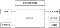
FIG. 1 is a schematic diagram of an automatic test system of the high-precision instrument of the present invention;
FIG. 2 is a schematic diagram showing the connection of the circuit part of the main control chip of the single chip microcomputer control circuit;
FIG. 3 is a schematic diagram showing the connection of the circuit part of the main control chip of the single chip microcomputer control circuit;
FIG. 4 is a circuit diagram of the peripheral portion of the main control chip circuit according to the present invention;
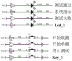
FIG. 5 is a schematic diagram of a button and display circuit of the test motherboard according to the present invention;
FIG. 6 is a circuit diagram of an extended portion of the USB _ HUB slave device of the present invention;
FIG. 7 is a circuit diagram of an extended portion of a USB _ HUB slave device according to the present invention
FIG. 8 is a digital power supply circuit diagram of the present invention;
FIG. 9 is a circuit diagram of a signal generator according to the present invention;
FIG. 10 is a circuit diagram of an electronic load according to the present invention;
FIG. 11 is a circuit diagram of an oscilloscope of the present invention;
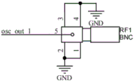
FIG. 12 is a circuit diagram of a digital multimeter of the present invention;
FIG. 13 is a circuit diagram of one CON32X2 chip of the daughter board interface of the present invention;
FIG. 14 is a circuit diagram of one CON32X2 chip of the daughter board interface of the present invention;
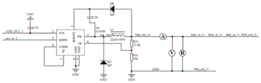
FIG. 15 is a circuit diagram of an LT1936 connection of the present invention;
FIG. 16 is a diagram of an interface for managing terminals of the test system according to the present invention.
Detailed Description
A high precision instrument based automatic test system is described in further detail below with reference to specific examples, which are provided for purposes of comparison and explanation only and to which the present invention is not limited.
In the description of the present invention, it is to be understood that the terms "upper", "lower", "left", "right", "top", "bottom", and the like, indicate orientations or positional relationships based on those shown in the drawings, and are only for convenience in describing the present invention and simplifying the description, but do not indicate or imply that the device or element referred to must have a specific orientation, be constructed in a specific orientation, and be operated, and thus, should not be construed as limiting the present invention.
In an embodiment, an automatic test system based on a high-precision instrument is provided, as shown in fig. 1, the automatic test system based on the high-precision instrument is provided, which includes a test motherboard, a power supply, a signal generator, an oscilloscope, an electronic load, a digital multimeter and a test system management terminal;
the power supply, the signal generator, the oscilloscope, the electronic load and the digital multimeter are all connected with the test motherboard;
the test system management terminal is communicated with the test motherboard through a high-speed USB serial interface;
the test motherboard is used for forwarding communication information of the test system management terminal, and after the device to be tested is connected with the test motherboard, the measurement information of the device to be tested is read and fed back to the test system management terminal;
the test motherboard is used for forwarding communication information of the test system management terminal, and after the device to be tested is connected with the test motherboard, the test system management terminal is used for being connected with the test motherboard by reading the test system management terminal, so that the received test information of the test motherboard is converted, the model of the device to be tested is automatically adapted, and the communication result and the test data result are displayed and the test data result is stored; measuring information of the equipment to be tested is taken, and the measuring information is fed back to a test system management terminal;
the communication result comprises whether the communication connection between the test motherboard and the equipment to be tested is successful, and the test data result comprises the model information of the equipment to be tested and whether the connection of each port of the equipment to be tested is normal.
The test motherboard comprises a singlechip control circuit, a USB _ HUB slave equipment extension circuit, an equipment interface and a daughter board interface.
Preferably, the single chip microcomputer control circuit is used for displaying a test process and a test result, controlling a test flow, realizing a graphic function by using an IO port of the single chip microcomputer, and communicating with the equipment to be tested.
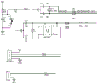
As shown in fig. 2~5, fig. 2 and fig. 3 are main control chip circuits of a single chip microcomputer control circuit, fig. 4 is a peripheral portion of the main control chip circuit, which includes a reset circuit, an 8M crystal oscillator circuit, an RTC circuit and a debug interface circuit, and fig. 5 is a USB test circuit diagram, which mainly provides a USB interface to communicate with a test system management terminal.
1. The singlechip control circuit:
the partial circuit mainly provides a USB to communicate with a host computer, is used for displaying a test process and a test result, simultaneously controls a test flow, subsequently utilizes an IO port of a single chip microcomputer to realize a graphic function, and can communicate with a device to be tested.
The single chip circuit realizes a man-machine interaction system and provides external test keys and test result display; and controlling the test flow through the keys, and displaying the test result and the system state by using the LED. In this embodiment, the system uses the high-speed high-precision clock 8M and the RTC clock as the clock inputs of the system, and generates the high-speed bus clock inside the chip by matching with the PLL frequency multiplication inside the STM32F407VGT6 chip, thereby implementing high-speed signal processing. The RTC clock is used to implement the clock.
The single chip microcomputer system realizes the control of an external testing instrument through the instruction of the upper computer, simultaneously collects the measurement information of the equipment, sends a test information packet to the upper computer after simply processing data, the main control chip adopts STM32F407VGT6, the chip adopts an ARM Cortex-M4 kernel, and various peripheral equipment are integrated in the chip, so that the system requirements can be met, and the chip has high running speed, reasonable price and capability of reducing the system cost.
Preferably, the USB _ HUB slave device expansion circuit is configured to add a host computer test system management terminal as a master device in an automatic test system based on a high-precision instrument, and perform communication with other devices as slave devices.
Preferably, the device interface and the daughter board interface are used for connecting external devices and the daughter board, and connecting the digital power supply, the signal generator, the electronic load, the oscilloscope, the multimeter and the device to be tested with the test mother board for testing.
Preferably, the USB _ HUB slave device expansion circuit, the device interface and the daughter board interface are respectively connected with the single chip microcomputer control circuit.
Preferably, the USB _ HUB slave device expansion circuit comprises 2 SL2.1A chips, 6U-USBAR 04P-F001 chips and 1 micro 5P _C77238chip.
As shown in fig. 6 and 7, the USB _ HUB slave device extension circuit diagram of the present invention is shown; the host computer test system management terminal is added to serve as a master device, other devices serve as slave devices to conduct communication, a USB _ HUB circuit is added to the motherboard for convenience of integration, and two SL2.1A chips are mainly used for completing circuit functions.
An upper computer is added in the test system of the invention as a main device, other devices are used as slave devices for communication, a USB _ HUB circuit is added on a motherboard for convenient integration, and two SL2.1A chips are mainly adopted to complete the circuit function.
The USB slave device circuit is used for realizing a USB _ HUB circuit, the circuit can realize one host and a plurality of slaves to realize the expansion of system devices, various measuring devices are integrated into a system, a USB master control is an STM32F407VGT6 chip, and the chip realizes the configuration and reading of various testing instruments through the partial circuit.
Preferably, the device interface includes a digital generator circuit, a signal generator circuit, an electronic load circuit, an oscilloscope circuit, and a digital multimeter circuit.
As shown in fig. 8 to 12, the schematic diagrams of the device interface digital power supply circuit, the signal generator circuit, the electronic load circuit, the oscilloscope circuit, and the universal meter circuit of the present invention are shown, and the circuit realizes the connection between the external device and the daughter board, and connects the digital power supply, the signal generator, the electronic load, the oscilloscope, the universal meter, and other devices with the motherboard for testing.
Preferably, the daughter board interface includes 2 CON32X2 chips.
As shown in fig. 13 and 14, the daughter board interface includes 2 CON32X2 chips, the test daughter board needs to be designed according to the principles of different chips to be tested, in this embodiment, an LT1936 chip is taken as an example, the chip is a buck power supply chip with a maximum 1.4A power output produced by Linear, and the function and parameter test of the chip can be basically realized through the test resources provided by the template.
The partial circuit is used for realizing the connection of external equipment and the daughter board, and connecting equipment such as a digital power supply, a signal generator, an electronic load, an oscilloscope, a universal meter and the like with the daughter board for testing.
The daughter board interface adopts the european style socket commonly used in this embodiment, can compatible part test instrument, and the equipment interface is the equipment interface commonly used, and convenient the change, the cost is lower.
The test daughter board needs to be designed according to the principle of different chips to be tested, taking an LT1936 chip as an example, the chip is a voltage reduction power supply chip with the maximum 1.4A power output produced by Linear, the function and parameter test of the chip can be basically realized through test resources provided by a template, and a mother board interface in the test daughter board is used for mother board connection. The interface can be used for more flexibly customizing and measuring various chips, the chip test meets the national standard requirement, and the measurement condition of a data manual is met.
In this embodiment, LT1936 is used as a device to be tested, as shown in an LT1936 connection circuit diagram in fig. 15, other devices in the system adopt two controllable power supplies 0 to 36v, two digital multimeters (model 2002: eight and half), one electronic load, two oscilloscopes and one signal generator, and a test motherboard provides LED display and key control functions at the same time, and by reading LT1936 chip information, a test system management terminal obtains an interface shown in fig. 16, and tests are performed through the following steps:
1) Reading a user configuration file, and setting a test flow, test conditions and the like according to the user configuration file;
2) The device is connected with an LT1936, automatically adapts to the model of the testing equipment, communicates and displays the communication result;
3) The user fills in information such as device model, process card, personnel and the like and then stores the information;
4) Clicking a starting test key to test;
5) And automatically processing and storing data after the test is finished.
Finally, it should be noted that the above embodiments are only used for illustrating the technical solutions of the present invention, and not for limiting the protection scope of the present invention, although the present invention is described in detail with reference to the preferred embodiments, it should be understood by those skilled in the art that modifications or equivalent substitutions can be made on the technical solutions of the present invention without departing from the spirit and scope of the technical solutions of the present invention.
Claims (8)
1. An automatic test system based on a high-precision instrument is characterized by comprising a test mother board, a power supply, a signal generator, an oscilloscope, an electronic load, a digital multimeter and a test system management terminal;
the power supply, the signal generator, the oscilloscope, the electronic load and the digital multimeter are all connected with the test motherboard;
the test system management terminal is communicated with the test motherboard through a high-speed USB serial interface;
the test motherboard is used for forwarding communication information of the test system management terminal, and after the device to be tested is connected with the test motherboard, the measurement information of the device to be tested is read and fed back to the test system management terminal;
the test motherboard is used for forwarding communication information of the test system management terminal, and after the device to be tested is connected with the test motherboard, the test system management terminal is used for being connected with the test motherboard by reading the test system management terminal, converting the received test information of the test motherboard, automatically adapting to the model of the device to be tested, displaying the communication result and the test data result and storing the test data result; measuring information of the equipment to be tested is taken, and the measuring information is fed back to a test system management terminal;
the test motherboard comprises a singlechip control circuit, a USB _ HUB slave equipment extension circuit, an equipment interface and a daughter board interface.
2. The automatic test system based on the high-precision instrument as claimed in claim 1, wherein the single chip microcomputer control circuit is used for displaying the test process and the test result, controlling the test flow, realizing the graphic function by using the IO port of the single chip microcomputer and communicating with the device to be tested.
3. The system according to claim 1, wherein the USB _ HUB slave device extension circuit is configured to add a host computer test system management terminal as a master device and other devices as slave devices to perform communication in the high-precision instrument based automatic test system.
4. The automatic test system based on the high-precision instrument as claimed in claim 1, wherein the device interface and the daughter board interface are used for connecting an external device and the daughter board, and connecting a digital power supply, a signal generator, an electronic load, an oscilloscope, a multimeter and a device to be tested with a test mother board for testing.
5. The automatic test system based on the high-precision instrument according to claim 1, wherein the USB _ HUB slave device expansion circuit, the device interface and the daughter board interface are respectively connected with a single chip microcomputer control circuit.
6. The high-precision instrument based automatic test system as claimed in claim 1, wherein the USB HUB slave device expansion circuit comprises 2 SL2.1A chips, 6U-USBAR 04P-F001 chips and 1 micro 5p _c77238chip.
7. A high accuracy instrument based automatic test system as claimed in claim 1, wherein said equipment interface includes digital generator circuitry, signal generator circuitry, electronic load circuitry, oscilloscope circuitry and digital multimeter circuitry.
8. The high accuracy instrument based automatic test system of claim 1, wherein the daughter board interface comprises 2 CON32X2 chips.
Priority Applications (1)
| Application Number | Priority Date | Filing Date | Title |
|---|---|---|---|
| CN202310066119.8A CN115792477A (en) | 2023-02-06 | 2023-02-06 | Automatic test system based on high-precision instrument |
Applications Claiming Priority (1)
| Application Number | Priority Date | Filing Date | Title |
|---|---|---|---|
| CN202310066119.8A CN115792477A (en) | 2023-02-06 | 2023-02-06 | Automatic test system based on high-precision instrument |
Publications (1)
| Publication Number | Publication Date |
|---|---|
| CN115792477A true CN115792477A (en) | 2023-03-14 |
Family
ID=85429987
Family Applications (1)
| Application Number | Title | Priority Date | Filing Date |
|---|---|---|---|
| CN202310066119.8A Pending CN115792477A (en) | 2023-02-06 | 2023-02-06 | Automatic test system based on high-precision instrument |
Country Status (1)
| Country | Link |
|---|---|
| CN (1) | CN115792477A (en) |
Cited By (1)
| Publication number | Priority date | Publication date | Assignee | Title |
|---|---|---|---|---|
| CN116520063A (en) * | 2023-06-26 | 2023-08-01 | 北京京瀚禹电子工程技术有限公司 | Automatic test system based on high-precision instrument |
Citations (7)
| Publication number | Priority date | Publication date | Assignee | Title |
|---|---|---|---|---|
| US20120095718A1 (en) * | 2010-10-18 | 2012-04-19 | Delta Electronics, Inc. | Automatic testing system and method |
| CN103389410A (en) * | 2013-07-10 | 2013-11-13 | 中国电子科技集团公司第四十一研究所 | Microwave power testing device based on universal serial bus (USB) interface |
| CN103792498A (en) * | 2014-02-14 | 2014-05-14 | 浪潮电子信息产业股份有限公司 | Automatic power supply testing method |
| CN112595965A (en) * | 2020-11-26 | 2021-04-02 | 西安太乙电子有限公司 | Test platform for analog circuit |
| CN112769434A (en) * | 2020-12-16 | 2021-05-07 | 中国电子科技集团公司第五十八研究所 | High-precision DAC test system based on FPGA |
| CN113848462A (en) * | 2021-10-27 | 2021-12-28 | 特变电工西安电气科技有限公司 | Automatic test platform and test method for PCBA single board in power electronic industry |
| CN114740339A (en) * | 2022-05-24 | 2022-07-12 | 俐玛光电科技(北京)有限公司 | Rapid integrated test method of integrated circuit based on independent instrument |
-
2023
- 2023-02-06 CN CN202310066119.8A patent/CN115792477A/en active Pending
Patent Citations (7)
| Publication number | Priority date | Publication date | Assignee | Title |
|---|---|---|---|---|
| US20120095718A1 (en) * | 2010-10-18 | 2012-04-19 | Delta Electronics, Inc. | Automatic testing system and method |
| CN103389410A (en) * | 2013-07-10 | 2013-11-13 | 中国电子科技集团公司第四十一研究所 | Microwave power testing device based on universal serial bus (USB) interface |
| CN103792498A (en) * | 2014-02-14 | 2014-05-14 | 浪潮电子信息产业股份有限公司 | Automatic power supply testing method |
| CN112595965A (en) * | 2020-11-26 | 2021-04-02 | 西安太乙电子有限公司 | Test platform for analog circuit |
| CN112769434A (en) * | 2020-12-16 | 2021-05-07 | 中国电子科技集团公司第五十八研究所 | High-precision DAC test system based on FPGA |
| CN113848462A (en) * | 2021-10-27 | 2021-12-28 | 特变电工西安电气科技有限公司 | Automatic test platform and test method for PCBA single board in power electronic industry |
| CN114740339A (en) * | 2022-05-24 | 2022-07-12 | 俐玛光电科技(北京)有限公司 | Rapid integrated test method of integrated circuit based on independent instrument |
Cited By (1)
| Publication number | Priority date | Publication date | Assignee | Title |
|---|---|---|---|---|
| CN116520063A (en) * | 2023-06-26 | 2023-08-01 | 北京京瀚禹电子工程技术有限公司 | Automatic test system based on high-precision instrument |
Similar Documents
| Publication | Publication Date | Title |
|---|---|---|
| CN106649166B (en) | A kind of universal used group of data processing system based on unified interface | |
| CN102759676B (en) | Capacitive screen comprehensive testing circuit, testing method and output data switching algorithm of testing method | |
| CN102445666B (en) | Laptop battery monitoring system and monitoring method | |
| CN115792477A (en) | Automatic test system based on high-precision instrument | |
| CN111190782A (en) | OCP3.0 interface function test fixture and method | |
| CN203025340U (en) | Test fixture detecting system | |
| CN115904835A (en) | Cable detection method and server | |
| CN106291321B (en) | L abWindows/CVI-based plasma power supply circuit automatic test platform and method | |
| CN212905201U (en) | Automatic power consumption test circuit of electronic product | |
| CN209281378U (en) | Chip commissioning device | |
| CN217385736U (en) | MCU's ATE equipment and system thereof | |
| CN115587000A (en) | High-speed interface board level application verification method and device | |
| CN211124351U (en) | Multifunctional data acquisition unit based on simulation and digital acquisition | |
| CN211653008U (en) | Integrated multi-instrument detector | |
| CN210465605U (en) | Multifunctional circuit board fault intelligent detection system | |
| CN107422276A (en) | Device and method is surveyed in a kind of power cabinet physical examination | |
| CN209231782U (en) | A kind of multi-channel portable test device for servo-system | |
| CN206161041U (en) | Gaseous monitoring node of local industrial environment based on bluetooth | |
| CN202453478U (en) | Laptop battery monitoring system | |
| CN112181122B (en) | Management device and method of digital power supply chip | |
| CN217279304U (en) | Aviation airborne electronic general platform based on FMQL | |
| CN112462911B (en) | High-density board card control architecture | |
| CN213365510U (en) | Accelerating card and server | |
| CN216118685U (en) | Power supply loop analysis tool based on CAN communication | |
| CN216696449U (en) | Current voltmeter |
Legal Events
| Date | Code | Title | Description |
|---|---|---|---|
| PB01 | Publication | ||
| PB01 | Publication | ||
| SE01 | Entry into force of request for substantive examination | ||
| SE01 | Entry into force of request for substantive examination | ||
| RJ01 | Rejection of invention patent application after publication | ||
| RJ01 | Rejection of invention patent application after publication |
Application publication date: 20230314 |