CN115767946A - Electronic circuit processing device for point-to-point welding of triode - Google Patents
Electronic circuit processing device for point-to-point welding of triode Download PDFInfo
- Publication number
- CN115767946A CN115767946A CN202211482782.8A CN202211482782A CN115767946A CN 115767946 A CN115767946 A CN 115767946A CN 202211482782 A CN202211482782 A CN 202211482782A CN 115767946 A CN115767946 A CN 115767946A
- Authority
- CN
- China
- Prior art keywords
- pair
- block
- groove
- frame
- circuit board
- Prior art date
- Legal status (The legal status is an assumption and is not a legal conclusion. Google has not performed a legal analysis and makes no representation as to the accuracy of the status listed.)
- Withdrawn
Links
Images


Abstract
The invention provides an electronic circuit processing device for point-to-point welding of a triode, which relates to the technical field of triode processing and comprises a bottom plate, wherein a cross electric slide rail is arranged at the upper end of the bottom plate, a first slide block is movably arranged at the upper end of the cross electric slide rail, and a supporting mechanism for clamping and positioning a circuit board is arranged at the upper end of the first slide block. According to the automatic pin bending device, the raw materials are placed in the guide frame by a user, the pins of the raw materials are inserted into the first guide grooves, then the raw materials drive the pins to slide in the first guide grooves along with the pushing of the third springs to the pushing plate and the raw materials, and then the pins are automatically bent under the guidance of the first guide grooves, so that the accuracy of bending the pins can be guaranteed, the pins can be more stably inserted into holes in the surface of a circuit board, and meanwhile, the pins are prevented from being damaged when being bent due to the cooperation of the inclined planes arranged in the first guide grooves.
Description
Technical Field
The invention relates to the technical field of processing of triodes, in particular to an electronic circuit processing device for welding a triode in a point-to-point mode.
Background
A transistor, also called a bipolar transistor or a transistor, is a semiconductor device for controlling current. The function is to amplify weak signals into electrical signals with large amplitude values, and the electrical signals are also used as contactless switches. When the triode is used, the triode needs to be welded and installed on a circuit board, so that the triode and the circuit board form a whole, when the triode is installed in a welding mode, generally, the pins of the triode are manually bent, then the pins of the triode are inserted into the circuit board, and finally the pins and the circuit board are welded.
Disclosure of Invention
Aiming at the defects of the prior art, the invention provides an electronic circuit processing device for welding a triode in a point-to-point mode, which solves the problems that when a user manually bends a pin of the triode, the required angle of the pin cannot be accurately bent, the pin needs to be bent for multiple times to reach the required angle and interval, the connection part of the triode and the pin is damaged when the pin is bent for multiple times, and the triode cannot normally work.
In order to achieve the purpose, the invention adopts the technical scheme that:
an electronic circuit processing device for triode point-to-point welding comprises a bottom plate, wherein a cross electric slide rail is mounted at the upper end of the bottom plate, a first slide block is movably mounted at the upper end of the cross electric slide rail, a supporting mechanism for clamping and positioning a circuit board is mounted at the upper end of the first slide block, the supporting mechanism comprises a connecting plate, the connecting plate and the first slide block are fixedly connected, clamping frames are respectively movably mounted at two ends of the upper surface of the connecting plate, and the circuit board is clamped and mounted between the clamping frames;
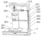
the welding device comprises a base plate, a positioning welding mechanism, a first supporting plate and a second supporting plate, wherein the rear side of the base plate is provided with the positioning welding mechanism, the positioning welding mechanism comprises a supporting frame, the supporting frame is fixedly arranged on the rear side of the base plate, the lower end of the front surface of the supporting frame is movably provided with the first supporting plate, the upper end of the first supporting plate is provided with a welding head and a tin bar, the welding head is used for welding the raw material and the circuit board, and the welding head, the tin bar and the circuit board are vertically parallel;
the upper end of the supporting frame is movably provided with a fixed block, the rear side of the fixed block is provided with a guide frame, and the raw material is movably arranged inside the fixed block and the guide frame;
the upper end in the fixed block is movably provided with a pushing block, the pushing block is vertically parallel to the raw material, and the pushing block, the raw material, the circuit board and the welding head are vertically parallel;
the rear side of guide frame is installed and is used for driving first backup pad and follow the connection rope that removes, and connects interconnect between rope and the first backup pad.
Preferably, a plurality of positioning holes are respectively formed in two ends of the upper surface of the connecting plate, a plurality of positioning rods are fixedly mounted on the lower surface of the clamping frame respectively, and the positioning rods are clamped and mounted inside the positioning holes respectively;
the front surface of the clamping frame and one side close to each other are respectively provided with a clamping groove, and the two ends of the circuit board are respectively clamped and installed in the clamping grooves.
Preferably, the front ends of the upper surfaces of the first supporting plates are respectively provided with a plurality of welding heads, and the upper ends of the welding heads are respectively in one-to-one correspondence with the pins of the raw materials;
the front end of the upper surface of the first supporting plate is respectively fixedly provided with a supporting column, the welding head and the supporting column are all in an inclined state, and the upper ends of the welding head and the supporting column are close to each other;
and the upper ends in the supporting columns are respectively and movably provided with tin bars.
Preferably, the movable blocks are movably arranged at the upper ends of the inner parts of the supporting columns in a penetrating mode respectively, the first springs are arranged in the supporting columns respectively and are connected with the movable blocks, the clamping grooves are formed in the upper ends of the movable blocks respectively, and the tin bars are clamped and arranged in the clamping grooves respectively.
Preferably, the lower end of the inside of the fixed block is provided with a first groove in a penetrating manner, and the guide frame is movably, fixedly and penetratively arranged on the rear side of the fixed block and is connected with the first groove;
promote a movable mounting in the inside upper end of first recess, fixed connection between the upper end of promotion piece and the output of cylinder, the cylinder is installed in the upper end of support frame, and the output of cylinder activity respectively runs through the inside of support frame and fixed block.
Preferably, the inner lower surface of the guide frame is provided with a first guide groove for guiding and bending the pins of the raw material in a penetrating manner;
the raw materials are respectively and movably arranged in the first groove and the guide frame, and pins of the raw materials are respectively clamped and arranged in the first guide groove;
the inside of guide frame and the one end movable mounting who keeps away from the fixed block have a catch plate, install the third spring between one side that the fixed block was kept away from to the catch plate and the guide frame, the catch plate is used for promoting the raw materials.
Preferably, the inside upper end of fixed block is equipped with the second recess, the output activity of cylinder is run through and is installed in the inside of second recess, is located inside the second recess cylinder output outside fixed mounting has the stripper plate, is located between stripper plate and the second recess the second spring is established to cylinder output outside cover and is installed.
Preferably, four corners of the lower surface of the fixed block are respectively provided with a rubber block;
the lower surface both ends of fixed block are equipped with the movable groove respectively, the inside of movable groove and the one end of keeping away from each other respectively fixed mounting have the dead lever, the pole body outside of dead lever is the activity respectively and runs through the installation and is equipped with the second backup pad, the one end that the second backup pad is close to each other is movable mounting respectively in the inside of first recess, and laminates mutually between second backup pad and the raw materials, the inside upper end of movable groove is equipped with the third recess respectively, the extension spring is installed respectively to the inside of third recess, and the lower extreme of extension spring respectively with the second backup pad between interconnect.
Preferably, the front surface of support frame is equipped with the spout, the inside movable mounting of spout has the second slider, fixed connection between the front end of second slider and the first backup pad, fixed mounting has the auxiliary rod respectively at the inside both ends of spout, the both ends of second slider are the movable through installation in the pole body outside of auxiliary rod respectively, the inside upper end of spout is run through and is equipped with the second guiding groove, and connects the inside of rope movable mounting at the second guiding groove.
Preferably, the upper end and the lower end of the connecting rope are respectively connected with the guide frame and the second sliding block, the roller is movably mounted at the corner inside the second guide groove, and the surfaces of the connecting rope and the roller are mutually attached.
1. According to the invention, a user puts raw materials into the guide frame, so that pins of the raw materials are inserted into the first guide groove, then the raw materials drive the pins to slide in the first guide groove along with the pushing of the third spring on the pushing plate and the raw materials, and then the automatic pin bending work is realized through the guide of the first guide groove, so that the pin bending accuracy can be ensured, the pins can be more stably inserted into holes on the surface of a circuit board, and meanwhile, the inclined plane arranged by matching with the first guide groove reduces the damage to the pins during the bending process, and the pins can be better protected.
2. According to the invention, a user clamps and installs a circuit board between clamping grooves, then adjusts the position of the circuit board through the matching of a cross electric sliding rail and a first sliding block, so that the circuit board is required to be inserted into a hole of a triode and raw materials to be overlapped up and down, then the fixed block and a pushing block can be pushed through an air cylinder, the fixed block drives the raw materials to move downwards, then when a rubber pad is contacted with the surface of the circuit board, the fixed block stops working, the air cylinder continues to extrude the raw materials through the pushing block, the raw materials drive pins to be inserted into the holes, so that point alignment installation is realized, and then welding work is carried out between the pins and the circuit board through a welding head and a tin bar.
3. According to the invention, the second supporting plate is pulled by the tension spring to position the raw material, so that the raw material cannot fall out of the first groove, then when the pushing block pushes the raw material downwards, the second supporting plate can rotate with the fixed rod as an axis along with the downward movement of the raw material, and the tension spring is pulled at the same time, so that the raw material cannot be obstructed to perform point-to-point installation work.
4. When the guide frame moves downwards along with the fixed block, the guide frame can upwards pull the second sliding block and the first supporting plate through the connecting rope, so that the first supporting plate drives the welding head and the tin bar to move upwards, welding work between the circuit board and the pins can be directly carried out after the pins of the raw materials are inserted into the circuit board, the whole welding efficiency is greatly improved, and when the guide frame moves upwards again, the first supporting plate can drive the connecting rope and the welding head to move downwards through weight, so that the cross-shaped electric slide rail cannot be prevented from driving the circuit board to carry out position adjustment work, and the guide frame is simple and convenient.
5. According to the invention, a user inserts the tin bar into the clamping groove, so that the tin bar and the movable block form a whole body, then the movable block and the tin bar are pushed by the first spring, so that the tin bar is always in contact with the circuit board and the pins, and then when the tin bar is used up or the length of the tin bar is insufficient, the tin bar can be rapidly replaced by only drawing out the tin bar, so that the tin bar replacement is more rapid.
Drawings
FIG. 1 is a schematic three-dimensional structure of the present invention;
FIG. 2 is a schematic three-dimensional structure of the guide frame of the present invention;
FIG. 3 is a schematic elevation view of the present invention;
FIG. 4 is a schematic side view of the present invention;
FIG. 5 isbase:Sub>A perspective view of the cross-sectional structure of FIG. 3 taken at A-A;
FIG. 6 is a perspective view of the cross-sectional structure of FIG. 4 at B-B;
FIG. 7 is a perspective view of the cross-sectional structure of FIG. 4 at C-C;
FIG. 8 is an enlarged perspective view of the structure at D in FIG. 5
FIG. 9 is an enlarged perspective view of FIG. 5 at E;
fig. 10 is an enlarged perspective view of fig. 7 at F.
In the figure: 1. a base plate; 2. a cross electric slide rail; 201. a first slider; 3. a support mechanism; 301. a connecting plate; 302. a clamping frame; 303. positioning a rod; 304. positioning holes; 305. a clamping groove; 4. a circuit board; 5. positioning a welding mechanism; 501. a support frame; 502. a chute; 503. an auxiliary lever; 504. a second slider; 505. a first support plate; 506. welding a head; 507. a support pillar; 508. a movable block; 509. a first spring; 510. a clamping groove; 511. tin bars; 512. a fixed block; 513. a guide frame; 514. a first guide groove; 515. a first groove; 516. a rubber block; 517. a pushing block; 518. a cylinder; 519. a second groove; 520. a second spring; 521. a pressing plate; 522. a movable groove; 523. a third groove; 524. a tension spring; 525. a second support plate; 526. fixing the rod; 527. a roller; 528. a push plate; 529. a third spring; 530. connecting ropes; 531. a second guide groove; 6. raw materials.
Detailed Description
The technical solutions in the embodiments of the present invention will be clearly and completely described below with reference to the embodiments of the present invention, and it is obvious that the described embodiments are only a part of the embodiments of the present invention, and not all of the embodiments. All other embodiments, which can be obtained by a person skilled in the art without making any creative effort based on the embodiments in the present invention, belong to the protection scope of the present invention.
As shown in fig. 1 to 10, an electronic circuit processing device for transistor point-to-point welding includes a base plate 1, a cross electric slide rail 2 is mounted at an upper end of the base plate 1, a first slider 201 is movably mounted at an upper end of the cross electric slide rail 2, a supporting mechanism 3 for clamping and positioning a circuit board 4 is mounted at an upper end of the first slider 201, the supporting mechanism 3 includes a connecting plate 301, the connecting plate 301 is fixedly connected with the first slider 201, clamping frames 302 are respectively movably mounted at two ends of an upper surface of the connecting plate 301, and the circuit board 4 is mounted between the clamping frames 302 in a clamping manner;
the positioning welding mechanism 5 is arranged on the rear side of the bottom plate 1, the positioning welding mechanism 5 comprises a support frame 501, the support frame 501 is fixedly arranged on the rear side of the bottom plate 1, a first support plate 505 is movably arranged at the lower end of the front surface of the support frame 501, a welding head 506 and a tin bar 511 which are used for welding the raw material 6 and the circuit board 4 are arranged at the upper end of the first support plate 505, and the welding head 506 is vertically parallel to the tin bar 511 and the circuit board 4;
a fixed block 512 is movably mounted at the upper end of the support frame 501, a guide frame 513 is mounted at the rear side of the fixed block 512, and the raw material 6 is movably mounted inside the fixed block 512 and the guide frame 513;
the push block 517 is movably installed at the upper end inside the fixed block 512, the push block 517 is parallel to the raw material 6 up and down, and the push block 517, the raw material 6, the circuit board 4 and the welding head 506 are vertically parallel;
the rear side of the guide frame 513 is installed with a connection rope 530 for driving the first support plate 505 to move, and the connection rope 530 and the first support plate 505 are connected with each other.
As shown in fig. 5 and 7, two ends of the upper surface of the connecting plate 301 are respectively provided with a plurality of positioning holes 304, the lower surface of the clamping frame 302 is respectively fixedly provided with a plurality of positioning rods 303, and the positioning rods 303 are respectively mounted inside the positioning holes 304 in a clamping manner; clamping grooves 305 are respectively formed on the front surfaces of the clamping frames 302 at the sides close to each other, and both ends of the circuit board 4 are respectively clamped and installed in the clamping grooves 305.
The user can be according to circuit board 4's size, adjust the interval between the holding frame 302, let holding frame 302 drive the inside that locating lever 303 inserted locating hole 304 can realize the positioning work to holding frame 302, then only need insert the inside of centre gripping groove 305 to circuit board 4, can accomplish the work of placing to circuit board 4, then through the cooperation of cross electric slide rail 2 with first slider 201, drive holding frame 302 and circuit board 4 and remove, the lower extreme to fixed block 512 is removed to the required counter point of circuit board 4 installation raw materials 6's one end, let parallel to each other between raw materials 6's pin and the circuit board 4, be convenient for later stage raw materials 6 drive the inside that the pin inserted circuit board 4, it is more convenient.
As shown in fig. 9, a plurality of welding heads 506 are respectively installed at the front ends of the upper surfaces of the first support plates 505, and the upper ends of the welding heads 506 respectively correspond to the pins of the raw material 6 one by one; the front ends of the upper surfaces of the first support plates 505 are respectively fixedly provided with support pillars 507, the welding heads 506 and the support pillars 507 are in an inclined state, and the upper ends of the welding heads 506 and the upper ends of the support pillars 507 are close to each other; the inside upper end of support column 507 movable mounting has tin bar 511 respectively, and the movable block 508 is installed in the activity of respectively running through in the inside upper end of support column 507, and interconnected between first spring 509 and the movable block 508 is installed respectively to the inside of support column 507, and the upper end of movable block 508 is equipped with the block groove 510 respectively, and the inside at block groove 510 is installed in tin bar 511 block respectively.
The solder joint 506 and the support column 507 drive the solder strip 511 to form an inclined state, so that the pins are directly positioned between the solder joint 506 and the solder strip 511 after being inserted into the circuit board 4 in the later period, and then the pins and the circuit board 4 can be soldered by the solder joint 506 and the solder strip 511;
then through the promotion of first spring 509 to movable block 508 and tin bar 511, let tin bar 511 all the time can both with the circuit board 4 and the department of meeting between the pin, avoid tin bar 511 to shorten after long-time use and can't continue to cooperate soldered connection 506 to carry out weldment work to the pin, the user only need take out after inserting tin bar 511 to realize the change work to tin bar 511 simultaneously, more swift.
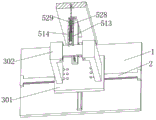
As shown in fig. 2, 5, 6 and 8, a first groove 515 is penetratingly formed at the inner lower end of the fixing block 512, and the guide frame 513 is movably and fixedly penetratingly installed at the rear side of the fixing block 512 and interconnected with the first groove 515; the pushing block 517 is movably mounted at the upper end of the inside of the first groove 515, the upper end of the pushing block 517 is fixedly connected with the output end of the air cylinder 518, the air cylinder 518 is mounted at the upper end of the support frame 501, the output end of the air cylinder 518 respectively and movably penetrates through the inside of the support frame 501 and the inside of the fixed block 512, and the lower surface of the inside of the guide frame 513 is provided with a first guide groove 514 for guiding and bending the pins of the raw material 6 in a penetrating manner; the raw materials 6 are respectively and movably arranged in the first groove 515 and the guide frame 513, and pins of the raw materials 6 are respectively clamped and arranged in the first guide grooves 514; the inside of guide frame 513 and the one end movable mounting who keeps away from fixed block 512 have a kickboard 528, install third spring 529 between one side that fixed block 512 was kept away from to kickboard 528 and the guide frame 513, kickboard 528 is used for promoting raw materials 6, the inside upper end of fixed block 512 is equipped with second recess 519, the output activity of cylinder 518 is run through and is installed in the inside of second recess 519, be located the inside cylinder 518 output outside fixed mounting of second recess 519 and have stripper plate 521, the cylinder 518 output outside cover that is located between stripper plate 521 and the second recess 519 is established and is installed second spring 520.
A user puts the raw material 6 into the guide frame 513, pins at the lower end of the raw material 6 are inserted into the first guide grooves 514, then when the third springs 529 push the raw material 6 through the push plates 528, the pins move along with the movement of the raw material 6 in the first guide grooves 514, and then the pins are automatically bent by matching with the bending angles arranged on the first guide grooves 514, so that the pins can be bent accurately at the angles, the damage between the pins and the raw material 6 is reduced, and the raw material 6 is better protected;
the first guide grooves 514 are three grooves, the middle groove is a straight line, the grooves on the two sides are respectively offset towards the two sides, so that when the raw material 6 drives the pins to slide in the first guide grooves 514, the pins can be bent through the grooves on the two sides, the upper ends of the grooves on the two sides are respectively provided with an inclined surface, the pins are assisted to be stretched when being bent through the inclined surfaces, and the damage to the pins in the bending process is reduced;
then after the raw material 6 enters the inside of the first groove 515 by the pushing of the pushing plate 528 and the third spring 529, the raw material 6 is supported by the second supporting plate 525 and stably located inside the first groove 515 without falling;
then when the raw material 6 needs to be installed at a fixed point, the air cylinder 518 drives the fixing block 512 and the pushing block 517 to move downwards through the output end, when the fixing block 512 drives the rubber block 516 to be in contact with the circuit board 4, the fixing block 512 stops moving, meanwhile, the air cylinder 518 continues to drive the fixing block 512 to move downwards through the output end, then, in the process of moving the output end, the second spring 520 is extruded through the extrusion plate 521, so that the fixing block 512 does not block the movement of the output end when the output end moves, then, when the output end of the air cylinder 518 drives the pushing block 517 to push the raw material 6 downwards, the raw material 6 is extruded to the second support plate 525 along with the downward movement of the raw material 6, the second support plate 525 opens the lower end of the first groove 515, and the raw material 6 drives the pins to be inserted into the circuit board 4;
then after the raw material 6 is inserted completely, the cylinder 518 can drive the pushing block 517 and the fixing block 512 to move upwards, and meanwhile, after the pushing block 517 is reset completely, the pushing plate 528 can cooperate with the third spring 529 to push the lower end of the pushing block 517 to the next raw material 6, so that the next raw material 6 is waited to be subjected to fixed-point installation, and the installation is more convenient and fast.
As shown in fig. 10, rubber blocks 516 are respectively mounted at four corners of the lower surface of the fixing block 512; the lower surface both ends of fixed block 512 are equipped with movable groove 522 respectively, the inside of movable groove 522 and the one end of keeping away from each other respectively fixed mounting have dead lever 526, the pole body outside of dead lever 526 is the movable through mounting respectively has second backup pad 525, the one end that second backup pad 525 is close to each other is movable mounting respectively in the inside of first recess 515, and laminate each other between second backup pad 525 and the raw materials 6, the inside upper end of movable groove 522 is equipped with third recess 523 respectively, extension spring 524 is installed respectively to the inside of third recess 523, and the lower extreme of extension spring 524 interconnect between respectively and the second backup pad 525.
When raw materials 6 moves downwards along with the promotion that promotes piece 517, raw materials 6 can extrude second backup pad 525, let second backup pad 525 use dead lever 526 to rotate as the axle center, thereby open the lower extreme of first recess 515, let raw materials 6 can insert the inside of circuit board 4 through the lower extreme of first recess 515, the realization is to the installation work of raw materials 6, and can stimulate extension spring 524 when second backup pad 525 rotates, thereby be convenient for when later stage fixed block 512 resets with promotion piece 517, extension spring 524 can stimulate second backup pad 525, let it reset and carry out spacing work to next raw materials 6.
As shown in fig. 5, a sliding groove 502 is provided on a front surface of the supporting frame 501, a second slider 504 is movably mounted inside the sliding groove 502, a front end of the second slider 504 is fixedly connected with the first supporting plate 505, auxiliary rods 503 are respectively fixedly mounted at two ends inside the sliding groove 502, two ends of the second slider 504 are respectively movably mounted outside a rod body of the auxiliary rods 503 in a penetrating manner, a second guiding groove 531 is arranged at an upper end inside the sliding groove 502 in a penetrating manner, a connecting rope 530 is movably mounted inside the second guiding groove 531, an upper end and a lower end of the connecting rope 530 are respectively connected with the guiding frame 513 and the second slider 504, a roller 527 is movably mounted at an inner corner of the second guiding groove 531, and the connecting rope 530 is attached to a surface of the roller 527.
When the guide frame 513 moves downwards, the guide frame 513 pulls the connecting rope 530 downwards, so that the connecting rope 530 pulls the second slider 504 and the first support plate 505 upwards, the first support plate 505 drives the welding head 506 and the tin bar 511 to move upwards, the raw material 6 is welded in the first time after the raw material 6 is inserted into the circuit board 4, and then when the guide frame 513 moves upwards, the welding head 506 and the connecting rope 530 are driven by the first support plate 505 and the second slider 504 through the self weight to move downwards to wait for the next welding of the raw material 6;
when the second sliding block 504 slides in the sliding groove 502, the auxiliary rod 503 can move in cooperation with the second sliding block 504, so that the moving efficiency of the second sliding block 504 is improved, and the second sliding block 504 is prevented from colliding in the sliding groove 502;
abrasion generated when the connection rope 530 moves inside the second guide groove 531 is reduced by the roller 527, and the service life of the connection rope 530 is prolonged.
The working principle of the electronic circuit processing device for welding the triode to the point is as follows:
when the positioning device is used, firstly, a user adjusts the distance between the clamping frames 302 according to the size of the circuit board 4, the clamping frames 302 drive the positioning rods 303 to be inserted into the positioning holes 304, so that the positioning work of the clamping frames 302 can be realized, then, the circuit board 4 can be placed only by inserting the circuit board 4 into the clamping grooves 305, and then, the clamping frames 302 and the circuit board 4 are driven to carry out position adjustment through the matching of the cross electric slide rail 2 and the first slide block 201;
then after the position of the circuit board 4 is adjusted, when the third spring 529 pushes the raw material 6 through the pushing plate 528, the pins move along with the moving of the raw material 6 in the first guide grooves 514, and then the pins are automatically bent by matching with the bending angle formed by the first guide grooves 514, the bent raw material 6 is pushed into the first grooves 515 to be vertically parallel to the pushing blocks 517, and then the cylinder 518 drives the fixing blocks 512 and the guide frames 513 to move downwards through the output end;
meanwhile, when the guide frame 513 moves downwards, the guide frame 513 pulls the connecting rope 530 downwards, so that the connecting rope 530 pulls the second slider 504 and the first supporting plate 505 upwards, and the first supporting plate 505 drives the soldering head 506 and the solder strip 511 to move upwards;
then when the fixed block 512 drives the rubber block 516 to contact the circuit board 4, the fixed block 512 stops moving, and meanwhile, the air cylinder 518 continues to drive the fixed block 512 to move downwards through the output end, and then in the process of moving the output end, the second spring 520 is extruded through the extrusion plate 521, so that the fixed block 512 does not block the movement of the output end when the output end moves, and then when the output end of the air cylinder 518 drives the pushing block 517 to push the raw material 6 downwards, the raw material 6 is extruded on the second support plate 525 along with the downward movement of the raw material 6, and the second support plate 525 opens the lower end of the first groove 515, so that the raw material 6 drives the pins to be inserted into the circuit board 4;
after the lead is inserted into the circuit board 4, the lead is soldered to the circuit board 4 by the solder head 506 and the solder bar 511.
It should be understood that the above-mentioned embodiments of the present invention are only examples for clearly illustrating the present invention, and are not intended to limit the embodiments of the present invention, and that various other modifications and changes can be made on the basis of the above description by those skilled in the art.
Claims (10)
1. The utility model provides a triode is to point welded electronic circuit processingequipment, includes bottom plate (1), its characterized in that: a cross electric slide rail (2) is mounted at the upper end of the bottom plate (1), a first slide block (201) is movably mounted at the upper end of the cross electric slide rail (2), a supporting mechanism (3) for clamping and positioning a circuit board (4) is mounted at the upper end of the first slide block (201), the supporting mechanism (3) comprises a connecting plate (301), the connecting plate (301) is fixedly connected with the first slide block (201), clamping frames (302) are respectively and movably mounted at two ends of the upper surface of the connecting plate (301), and the circuit board (4) is clamped and mounted between the clamping frames (302);
the welding device is characterized in that a positioning welding mechanism (5) is installed on the rear side of the bottom plate (1), the positioning welding mechanism (5) comprises a support frame (501), the support frame (501) is fixedly installed on the rear side of the bottom plate (1), a first support plate (505) is movably installed at the lower end of the front surface of the support frame (501), a welding head (506) and a tin bar (511) which are used for welding the raw material (6) and the circuit board (4) are installed at the upper end of the first support plate (505), and the welding head (506) is vertically parallel to the tin bar (511) and the circuit board (4);
the upper end of the supporting frame (501) is movably provided with a fixed block (512), the rear side of the fixed block (512) is provided with a guide frame (513), and the raw material (6) is movably arranged in the fixed block (512) and the guide frame (513);
the upper end in the fixed block (512) is movably provided with a pushing block (517), the pushing block (517) is parallel to the raw material (6) up and down, and the pushing block (517), the raw material (6), the circuit board (4) and the welding head (506) are vertically parallel;
the rear side of the guide frame (513) is provided with a connecting rope (530) for driving the first supporting plate (505) to move along, and the connecting rope (530) is connected with the first supporting plate (505).
2. The apparatus of claim 1, wherein the pair of transistors are mounted in a pair of opposing mounting locations, the pair of mounting locations comprising: a plurality of positioning holes (304) are respectively formed in two ends of the upper surface of the connecting plate (301), a plurality of positioning rods (303) are respectively fixedly mounted on the lower surface of the clamping frame (302), and the positioning rods (303) are respectively clamped and mounted in the positioning holes (304);
clamping grooves (305) are respectively formed in the front surface of the clamping frame (302) and one side, close to each other, of the clamping frame, and two ends of the circuit board (4) are respectively clamped and installed in the clamping grooves (305).
3. The apparatus of claim 1, wherein the pair of transistors are mounted in a pair of opposing mounting locations, the pair of mounting locations comprising: a plurality of welding heads (506) are respectively installed at the front ends of the upper surfaces of the first supporting plates (505), and the upper ends of the welding heads (506) are respectively in one-to-one correspondence with the pins of the raw materials (6);
support columns (507) are fixedly mounted at the front ends of the upper surfaces of the first support plates (505), the welding heads (506) and the support columns (507) are all set to be in an inclined state, and the upper ends of the welding heads (506) and the upper ends of the support columns (507) are close to each other;
and the upper ends of the insides of the supporting columns (507) are respectively and movably provided with tin bars (511).
4. The apparatus of claim 3, wherein the pair of transistors are mounted in a pair of opposing mounting locations, the pair of mounting locations comprising: the utility model discloses a tin bar fixing device, including support column (507), first spring (509) and activity piece (508), interconnect between the inside upper end of support column (507) is movably installed through movable block (508) respectively, the inside of support column (507) is installed first spring (509) and activity piece (508) respectively, the upper end of activity piece (508) is equipped with block groove (510) respectively, tin bar (511) block respectively installs the inside at block groove (510).
5. The apparatus of claim 1, wherein the transistor is connected to the point by a pair of wires, and the apparatus comprises: a first groove (515) is formed in the lower end of the inside of the fixed block (512) in a penetrating mode, and the guide frame (513) is fixedly installed on the rear side of the fixed block (512) in a penetrating mode in a moving mode and is connected with the first groove (515);
the utility model discloses a supporting frame, including the first recess (515), promote the inside upper end of piece (517), promote fixed connection between the upper end of piece (517) and the output of cylinder (518), cylinder (518) are installed in the upper end of supporting frame (501), and the inside of support frame (501) and fixed block (512) is run through in the activity respectively to the output of cylinder (518).
6. The apparatus of claim 1, wherein the pair of transistors are mounted in a pair of opposing mounting locations, the pair of mounting locations comprising: a first guide groove (514) for guiding and bending the pins of the raw material (6) penetrates through the inner lower surface of the guide frame (513);
the raw materials (6) are respectively and movably arranged in the first groove (515) and the guide frame (513), and pins of the raw materials (6) are respectively clamped and arranged in the first guide grooves (514);
the inside and keep away from the one end movable mounting of fixed block (512) of guide frame (513) have a push plate (528), install third spring (529) between the one side of push plate (528) keeping away from fixed block (512) and guide frame (513), push plate (528) are used for promoting raw materials (6).
7. The apparatus of claim 5, wherein the pair of transistors are mounted in a pair of opposing mounting locations, the pair of mounting locations comprising: the inside upper end of fixed block (512) is equipped with second recess (519), the output activity of cylinder (518) runs through the inside of installing in second recess (519), is located inside second recess (519) cylinder (518) output outside fixed mounting has stripper plate (521), is located between stripper plate (521) and second recess (519) cylinder (518) output outside cover is established and is installed second spring (520).
8. The apparatus of claim 1, wherein the pair of transistors are mounted in a pair of opposing mounting locations, the pair of mounting locations comprising: four corners of the lower surface of the fixed block (512) are respectively provided with a rubber block (516);
the lower surface both ends of fixed block (512) are equipped with movable groove (522) respectively, the inside of movable groove (522) and the one end of keeping away from each other respectively fixed mounting have dead lever (526), the pole body outside of dead lever (526) is movable respectively and is run through and install second backup pad (525), the inside of the one end difference movable mounting in first recess (515) that second backup pad (525) are close to each other, and laminate mutually between second backup pad (525) and raw materials (6), the inside upper end in movable groove (522) is equipped with third recess (523) respectively, extension spring (524) are installed respectively to the inside of third recess (523), and interconnect between the lower extreme of extension spring (524) respectively and second backup pad (525).
9. The apparatus of claim 1, wherein the pair of transistors are mounted in a pair of opposing mounting locations, the pair of mounting locations comprising: the positive surface of support frame (501) is equipped with spout (502), the inside movable mounting of spout (502) has second slider (504), fixed connection between the front end of second slider (504) and first backup pad (505), the inside both ends of spout (502) fixed mounting respectively has auxiliary rod (503), the both ends of second slider (504) are the activity respectively and are run through the pole body outside of installing at auxiliary rod (503), the inside upper end of spout (502) is run through and is equipped with second guide groove (531), and connects rope (530) movable mounting in the inside of second guide groove (531).
10. The apparatus of claim 9, wherein the pair of transistors are mounted in a point-to-point manner, and the apparatus further comprises: the upper end and the lower end of the connecting rope (530) are respectively connected with the guide frame (513) and the second sliding block (504), the inner corner of the second guide groove (531) is movably provided with a roller (527), and the surfaces of the connecting rope (530) and the roller (527) are mutually attached.
Priority Applications (1)
| Application Number | Priority Date | Filing Date | Title |
|---|---|---|---|
| CN202211482782.8A CN115767946A (en) | 2022-11-24 | 2022-11-24 | Electronic circuit processing device for point-to-point welding of triode |
Applications Claiming Priority (1)
| Application Number | Priority Date | Filing Date | Title |
|---|---|---|---|
| CN202211482782.8A CN115767946A (en) | 2022-11-24 | 2022-11-24 | Electronic circuit processing device for point-to-point welding of triode |
Publications (1)
| Publication Number | Publication Date |
|---|---|
| CN115767946A true CN115767946A (en) | 2023-03-07 |
Family
ID=85337762
Family Applications (1)
| Application Number | Title | Priority Date | Filing Date |
|---|---|---|---|
| CN202211482782.8A Withdrawn CN115767946A (en) | 2022-11-24 | 2022-11-24 | Electronic circuit processing device for point-to-point welding of triode |
Country Status (1)
| Country | Link |
|---|---|
| CN (1) | CN115767946A (en) |
-
2022
- 2022-11-24 CN CN202211482782.8A patent/CN115767946A/en not_active Withdrawn
Similar Documents
| Publication | Publication Date | Title |
|---|---|---|
| CN209772625U (en) | coating jig for automobile bumper | |
| CN103894673A (en) | Profile cutting center | |
| CN110900072B (en) | Positioning tool and welding equipment for left and right side plates of inflatable environment-friendly cabinet | |
| CN212558355U (en) | Auxiliary carrying device for workpieces | |
| CN115767946A (en) | Electronic circuit processing device for point-to-point welding of triode | |
| CN110323306B (en) | Solar cell string welding bus bar pulling device | |
| CN114888893B (en) | High-precision punching device and application thereof in circuit board processing | |
| CN111745033A (en) | Punching machine holds in palm work or material rest and uses its punching machine | |
| CN217571670U (en) | Automatic assembling device for junction box | |
| CN203778876U (en) | Sectional bar saw cutting center | |
| CN111037185A (en) | Automatic change door frame welding equipment | |
| CN111014918A (en) | Electric resistance welding mechanism for battery of floor sweeping robot | |
| CN214726438U (en) | Transfer shaping device | |
| CN216389402U (en) | Photovoltaic module tetrafluoro cloth erection equipment | |
| CN214878153U (en) | Automatic positioning and feeding device for PCB | |
| CN212411882U (en) | Accurate positioning mechanism for riveting point of silver contact | |
| CN113695436A (en) | Automatic machining device for motor coil end-to-end sleeve | |
| CN210173772U (en) | Full-automatic punching machine | |
| CN209811441U (en) | Laminate welding machine | |
| CN109079056B (en) | Terminal correction equipment with automatic discharge mechanism | |
| CN208292229U (en) | Automatic blanking device | |
| CN105537815A (en) | Solder strip drawing mechanism | |
| CN111167901A (en) | Automatic bending device for multiple terminals of connector | |
| CN112894043B (en) | Follow-up tail guiding clamping device of series welding machine and clamping method thereof | |
| CN218926894U (en) | Shaping mechanism and welding shaping equipment |
Legal Events
| Date | Code | Title | Description |
|---|---|---|---|
| PB01 | Publication | ||
| PB01 | Publication | ||
| SE01 | Entry into force of request for substantive examination | ||
| SE01 | Entry into force of request for substantive examination | ||
| WW01 | Invention patent application withdrawn after publication | ||
| WW01 | Invention patent application withdrawn after publication |
Application publication date: 20230307 |