CN115697742A - Power unit for vehicle and wheel bearing with generator - Google Patents
Power unit for vehicle and wheel bearing with generator Download PDFInfo
- Publication number
- CN115697742A CN115697742A CN202180041113.4A CN202180041113A CN115697742A CN 115697742 A CN115697742 A CN 115697742A CN 202180041113 A CN202180041113 A CN 202180041113A CN 115697742 A CN115697742 A CN 115697742A
- Authority
- CN
- China
- Prior art keywords
- inner ring
- vehicle
- wheel
- ring
- bracket
- Prior art date
- Legal status (The legal status is an assumption and is not a legal conclusion. Google has not performed a legal analysis and makes no representation as to the accuracy of the status listed.)
- Pending
Links
Images


Classifications
-
- H—ELECTRICITY
- H02—GENERATION; CONVERSION OR DISTRIBUTION OF ELECTRIC POWER
- H02K—DYNAMO-ELECTRIC MACHINES
- H02K7/00—Arrangements for handling mechanical energy structurally associated with dynamo-electric machines, e.g. structural association with mechanical driving motors or auxiliary dynamo-electric machines
- H02K7/14—Structural association with mechanical loads, e.g. with hand-held machine tools or fans
-
- B—PERFORMING OPERATIONS; TRANSPORTING
- B60—VEHICLES IN GENERAL
- B60K—ARRANGEMENT OR MOUNTING OF PROPULSION UNITS OR OF TRANSMISSIONS IN VEHICLES; ARRANGEMENT OR MOUNTING OF PLURAL DIVERSE PRIME-MOVERS IN VEHICLES; AUXILIARY DRIVES FOR VEHICLES; INSTRUMENTATION OR DASHBOARDS FOR VEHICLES; ARRANGEMENTS IN CONNECTION WITH COOLING, AIR INTAKE, GAS EXHAUST OR FUEL SUPPLY OF PROPULSION UNITS IN VEHICLES
- B60K17/00—Arrangement or mounting of transmissions in vehicles
- B60K17/34—Arrangement or mounting of transmissions in vehicles for driving both front and rear wheels, e.g. four wheel drive vehicles
- B60K17/354—Arrangement or mounting of transmissions in vehicles for driving both front and rear wheels, e.g. four wheel drive vehicles having separate mechanical assemblies for transmitting drive to the front or to the rear wheels or set of wheels
-
- B—PERFORMING OPERATIONS; TRANSPORTING
- B60—VEHICLES IN GENERAL
- B60K—ARRANGEMENT OR MOUNTING OF PROPULSION UNITS OR OF TRANSMISSIONS IN VEHICLES; ARRANGEMENT OR MOUNTING OF PLURAL DIVERSE PRIME-MOVERS IN VEHICLES; AUXILIARY DRIVES FOR VEHICLES; INSTRUMENTATION OR DASHBOARDS FOR VEHICLES; ARRANGEMENTS IN CONNECTION WITH COOLING, AIR INTAKE, GAS EXHAUST OR FUEL SUPPLY OF PROPULSION UNITS IN VEHICLES
- B60K17/00—Arrangement or mounting of transmissions in vehicles
- B60K17/34—Arrangement or mounting of transmissions in vehicles for driving both front and rear wheels, e.g. four wheel drive vehicles
- B60K17/356—Arrangement or mounting of transmissions in vehicles for driving both front and rear wheels, e.g. four wheel drive vehicles having fluid or electric motor, for driving one or more wheels
-
- B—PERFORMING OPERATIONS; TRANSPORTING
- B60—VEHICLES IN GENERAL
- B60K—ARRANGEMENT OR MOUNTING OF PROPULSION UNITS OR OF TRANSMISSIONS IN VEHICLES; ARRANGEMENT OR MOUNTING OF PLURAL DIVERSE PRIME-MOVERS IN VEHICLES; AUXILIARY DRIVES FOR VEHICLES; INSTRUMENTATION OR DASHBOARDS FOR VEHICLES; ARRANGEMENTS IN CONNECTION WITH COOLING, AIR INTAKE, GAS EXHAUST OR FUEL SUPPLY OF PROPULSION UNITS IN VEHICLES
- B60K6/00—Arrangement or mounting of plural diverse prime-movers for mutual or common propulsion, e.g. hybrid propulsion systems comprising electric motors and internal combustion engines ; Control systems therefor, i.e. systems controlling two or more prime movers, or controlling one of these prime movers and any of the transmission, drive or drive units Informative references: mechanical gearings with secondary electric drive F16H3/72; arrangements for handling mechanical energy structurally associated with the dynamo-electric machine H02K7/00; machines comprising structurally interrelated motor and generator parts H02K51/00; dynamo-electric machines not otherwise provided for in H02K see H02K99/00
- B60K6/20—Arrangement or mounting of plural diverse prime-movers for mutual or common propulsion, e.g. hybrid propulsion systems comprising electric motors and internal combustion engines ; Control systems therefor, i.e. systems controlling two or more prime movers, or controlling one of these prime movers and any of the transmission, drive or drive units Informative references: mechanical gearings with secondary electric drive F16H3/72; arrangements for handling mechanical energy structurally associated with the dynamo-electric machine H02K7/00; machines comprising structurally interrelated motor and generator parts H02K51/00; dynamo-electric machines not otherwise provided for in H02K see H02K99/00 the prime-movers consisting of electric motors and internal combustion engines, e.g. HEVs
- B60K6/42—Arrangement or mounting of plural diverse prime-movers for mutual or common propulsion, e.g. hybrid propulsion systems comprising electric motors and internal combustion engines ; Control systems therefor, i.e. systems controlling two or more prime movers, or controlling one of these prime movers and any of the transmission, drive or drive units Informative references: mechanical gearings with secondary electric drive F16H3/72; arrangements for handling mechanical energy structurally associated with the dynamo-electric machine H02K7/00; machines comprising structurally interrelated motor and generator parts H02K51/00; dynamo-electric machines not otherwise provided for in H02K see H02K99/00 the prime-movers consisting of electric motors and internal combustion engines, e.g. HEVs characterised by the architecture of the hybrid electric vehicle
- B60K6/44—Series-parallel type
- B60K6/448—Electrical distribution type
-
- B—PERFORMING OPERATIONS; TRANSPORTING
- B60—VEHICLES IN GENERAL
- B60K—ARRANGEMENT OR MOUNTING OF PROPULSION UNITS OR OF TRANSMISSIONS IN VEHICLES; ARRANGEMENT OR MOUNTING OF PLURAL DIVERSE PRIME-MOVERS IN VEHICLES; AUXILIARY DRIVES FOR VEHICLES; INSTRUMENTATION OR DASHBOARDS FOR VEHICLES; ARRANGEMENTS IN CONNECTION WITH COOLING, AIR INTAKE, GAS EXHAUST OR FUEL SUPPLY OF PROPULSION UNITS IN VEHICLES
- B60K6/00—Arrangement or mounting of plural diverse prime-movers for mutual or common propulsion, e.g. hybrid propulsion systems comprising electric motors and internal combustion engines ; Control systems therefor, i.e. systems controlling two or more prime movers, or controlling one of these prime movers and any of the transmission, drive or drive units Informative references: mechanical gearings with secondary electric drive F16H3/72; arrangements for handling mechanical energy structurally associated with the dynamo-electric machine H02K7/00; machines comprising structurally interrelated motor and generator parts H02K51/00; dynamo-electric machines not otherwise provided for in H02K see H02K99/00
- B60K6/20—Arrangement or mounting of plural diverse prime-movers for mutual or common propulsion, e.g. hybrid propulsion systems comprising electric motors and internal combustion engines ; Control systems therefor, i.e. systems controlling two or more prime movers, or controlling one of these prime movers and any of the transmission, drive or drive units Informative references: mechanical gearings with secondary electric drive F16H3/72; arrangements for handling mechanical energy structurally associated with the dynamo-electric machine H02K7/00; machines comprising structurally interrelated motor and generator parts H02K51/00; dynamo-electric machines not otherwise provided for in H02K see H02K99/00 the prime-movers consisting of electric motors and internal combustion engines, e.g. HEVs
- B60K6/42—Arrangement or mounting of plural diverse prime-movers for mutual or common propulsion, e.g. hybrid propulsion systems comprising electric motors and internal combustion engines ; Control systems therefor, i.e. systems controlling two or more prime movers, or controlling one of these prime movers and any of the transmission, drive or drive units Informative references: mechanical gearings with secondary electric drive F16H3/72; arrangements for handling mechanical energy structurally associated with the dynamo-electric machine H02K7/00; machines comprising structurally interrelated motor and generator parts H02K51/00; dynamo-electric machines not otherwise provided for in H02K see H02K99/00 the prime-movers consisting of electric motors and internal combustion engines, e.g. HEVs characterised by the architecture of the hybrid electric vehicle
- B60K6/48—Parallel type
-
- B—PERFORMING OPERATIONS; TRANSPORTING
- B60—VEHICLES IN GENERAL
- B60K—ARRANGEMENT OR MOUNTING OF PROPULSION UNITS OR OF TRANSMISSIONS IN VEHICLES; ARRANGEMENT OR MOUNTING OF PLURAL DIVERSE PRIME-MOVERS IN VEHICLES; AUXILIARY DRIVES FOR VEHICLES; INSTRUMENTATION OR DASHBOARDS FOR VEHICLES; ARRANGEMENTS IN CONNECTION WITH COOLING, AIR INTAKE, GAS EXHAUST OR FUEL SUPPLY OF PROPULSION UNITS IN VEHICLES
- B60K6/00—Arrangement or mounting of plural diverse prime-movers for mutual or common propulsion, e.g. hybrid propulsion systems comprising electric motors and internal combustion engines ; Control systems therefor, i.e. systems controlling two or more prime movers, or controlling one of these prime movers and any of the transmission, drive or drive units Informative references: mechanical gearings with secondary electric drive F16H3/72; arrangements for handling mechanical energy structurally associated with the dynamo-electric machine H02K7/00; machines comprising structurally interrelated motor and generator parts H02K51/00; dynamo-electric machines not otherwise provided for in H02K see H02K99/00
- B60K6/20—Arrangement or mounting of plural diverse prime-movers for mutual or common propulsion, e.g. hybrid propulsion systems comprising electric motors and internal combustion engines ; Control systems therefor, i.e. systems controlling two or more prime movers, or controlling one of these prime movers and any of the transmission, drive or drive units Informative references: mechanical gearings with secondary electric drive F16H3/72; arrangements for handling mechanical energy structurally associated with the dynamo-electric machine H02K7/00; machines comprising structurally interrelated motor and generator parts H02K51/00; dynamo-electric machines not otherwise provided for in H02K see H02K99/00 the prime-movers consisting of electric motors and internal combustion engines, e.g. HEVs
- B60K6/50—Architecture of the driveline characterised by arrangement or kind of transmission units
- B60K6/52—Driving a plurality of drive axles, e.g. four-wheel drive
-
- B—PERFORMING OPERATIONS; TRANSPORTING
- B60—VEHICLES IN GENERAL
- B60K—ARRANGEMENT OR MOUNTING OF PROPULSION UNITS OR OF TRANSMISSIONS IN VEHICLES; ARRANGEMENT OR MOUNTING OF PLURAL DIVERSE PRIME-MOVERS IN VEHICLES; AUXILIARY DRIVES FOR VEHICLES; INSTRUMENTATION OR DASHBOARDS FOR VEHICLES; ARRANGEMENTS IN CONNECTION WITH COOLING, AIR INTAKE, GAS EXHAUST OR FUEL SUPPLY OF PROPULSION UNITS IN VEHICLES
- B60K7/00—Disposition of motor in, or adjacent to, traction wheel
- B60K7/0007—Disposition of motor in, or adjacent to, traction wheel the motor being electric
-
- H—ELECTRICITY
- H02—GENERATION; CONVERSION OR DISTRIBUTION OF ELECTRIC POWER
- H02K—DYNAMO-ELECTRIC MACHINES
- H02K1/00—Details of the magnetic circuit
- H02K1/06—Details of the magnetic circuit characterised by the shape, form or construction
- H02K1/12—Stationary parts of the magnetic circuit
- H02K1/18—Means for mounting or fastening magnetic stationary parts on to, or to, the stator structures
- H02K1/185—Means for mounting or fastening magnetic stationary parts on to, or to, the stator structures to outer stators
-
- H—ELECTRICITY
- H02—GENERATION; CONVERSION OR DISTRIBUTION OF ELECTRIC POWER
- H02K—DYNAMO-ELECTRIC MACHINES
- H02K11/00—Structural association of dynamo-electric machines with electric components or with devices for shielding, monitoring or protection
- H02K11/20—Structural association of dynamo-electric machines with electric components or with devices for shielding, monitoring or protection for measuring, monitoring, testing, protecting or switching
- H02K11/21—Devices for sensing speed or position, or actuated thereby
- H02K11/215—Magnetic effect devices, e.g. Hall-effect or magneto-resistive elements
-
- H—ELECTRICITY
- H02—GENERATION; CONVERSION OR DISTRIBUTION OF ELECTRIC POWER
- H02K—DYNAMO-ELECTRIC MACHINES
- H02K21/00—Synchronous motors having permanent magnets; Synchronous generators having permanent magnets
- H02K21/12—Synchronous motors having permanent magnets; Synchronous generators having permanent magnets with stationary armatures and rotating magnets
- H02K21/14—Synchronous motors having permanent magnets; Synchronous generators having permanent magnets with stationary armatures and rotating magnets with magnets rotating within the armatures
- H02K21/16—Synchronous motors having permanent magnets; Synchronous generators having permanent magnets with stationary armatures and rotating magnets with magnets rotating within the armatures having annular armature cores with salient poles
-
- H—ELECTRICITY
- H02—GENERATION; CONVERSION OR DISTRIBUTION OF ELECTRIC POWER
- H02K—DYNAMO-ELECTRIC MACHINES
- H02K5/00—Casings; Enclosures; Supports
- H02K5/04—Casings or enclosures characterised by the shape, form or construction thereof
- H02K5/16—Means for supporting bearings, e.g. insulating supports or means for fitting bearings in the bearing-shields
- H02K5/173—Means for supporting bearings, e.g. insulating supports or means for fitting bearings in the bearing-shields using bearings with rolling contact, e.g. ball bearings
- H02K5/1737—Means for supporting bearings, e.g. insulating supports or means for fitting bearings in the bearing-shields using bearings with rolling contact, e.g. ball bearings radially supporting the rotor around a fixed spindle; radially supporting the rotor directly
-
- H—ELECTRICITY
- H02—GENERATION; CONVERSION OR DISTRIBUTION OF ELECTRIC POWER
- H02K—DYNAMO-ELECTRIC MACHINES
- H02K5/00—Casings; Enclosures; Supports
- H02K5/04—Casings or enclosures characterised by the shape, form or construction thereof
- H02K5/18—Casings or enclosures characterised by the shape, form or construction thereof with ribs or fins for improving heat transfer
-
- H—ELECTRICITY
- H02—GENERATION; CONVERSION OR DISTRIBUTION OF ELECTRIC POWER
- H02K—DYNAMO-ELECTRIC MACHINES
- H02K7/00—Arrangements for handling mechanical energy structurally associated with dynamo-electric machines, e.g. structural association with mechanical driving motors or auxiliary dynamo-electric machines
- H02K7/006—Structural association of a motor or generator with the drive train of a motor vehicle
-
- H—ELECTRICITY
- H02—GENERATION; CONVERSION OR DISTRIBUTION OF ELECTRIC POWER
- H02K—DYNAMO-ELECTRIC MACHINES
- H02K7/00—Arrangements for handling mechanical energy structurally associated with dynamo-electric machines, e.g. structural association with mechanical driving motors or auxiliary dynamo-electric machines
- H02K7/08—Structural association with bearings
- H02K7/086—Structural association with bearings radially supporting the rotor around a fixed spindle; radially supporting the rotor directly
- H02K7/088—Structural association with bearings radially supporting the rotor around a fixed spindle; radially supporting the rotor directly radially supporting the rotor directly
-
- H—ELECTRICITY
- H02—GENERATION; CONVERSION OR DISTRIBUTION OF ELECTRIC POWER
- H02K—DYNAMO-ELECTRIC MACHINES
- H02K9/00—Arrangements for cooling or ventilating
- H02K9/22—Arrangements for cooling or ventilating by solid heat conducting material embedded in, or arranged in contact with, the stator or rotor, e.g. heat bridges
- H02K9/227—Heat sinks
-
- B—PERFORMING OPERATIONS; TRANSPORTING
- B60—VEHICLES IN GENERAL
- B60B—VEHICLE WHEELS; CASTORS; AXLES FOR WHEELS OR CASTORS; INCREASING WHEEL ADHESION
- B60B27/00—Hubs
- B60B27/0015—Hubs for driven wheels
-
- B—PERFORMING OPERATIONS; TRANSPORTING
- B60—VEHICLES IN GENERAL
- B60B—VEHICLE WHEELS; CASTORS; AXLES FOR WHEELS OR CASTORS; INCREASING WHEEL ADHESION
- B60B27/00—Hubs
- B60B27/0047—Hubs characterised by functional integration of other elements
- B60B27/0068—Hubs characterised by functional integration of other elements the element being a sensor
-
- B—PERFORMING OPERATIONS; TRANSPORTING
- B60—VEHICLES IN GENERAL
- B60K—ARRANGEMENT OR MOUNTING OF PROPULSION UNITS OR OF TRANSMISSIONS IN VEHICLES; ARRANGEMENT OR MOUNTING OF PLURAL DIVERSE PRIME-MOVERS IN VEHICLES; AUXILIARY DRIVES FOR VEHICLES; INSTRUMENTATION OR DASHBOARDS FOR VEHICLES; ARRANGEMENTS IN CONNECTION WITH COOLING, AIR INTAKE, GAS EXHAUST OR FUEL SUPPLY OF PROPULSION UNITS IN VEHICLES
- B60K6/00—Arrangement or mounting of plural diverse prime-movers for mutual or common propulsion, e.g. hybrid propulsion systems comprising electric motors and internal combustion engines ; Control systems therefor, i.e. systems controlling two or more prime movers, or controlling one of these prime movers and any of the transmission, drive or drive units Informative references: mechanical gearings with secondary electric drive F16H3/72; arrangements for handling mechanical energy structurally associated with the dynamo-electric machine H02K7/00; machines comprising structurally interrelated motor and generator parts H02K51/00; dynamo-electric machines not otherwise provided for in H02K see H02K99/00
- B60K6/20—Arrangement or mounting of plural diverse prime-movers for mutual or common propulsion, e.g. hybrid propulsion systems comprising electric motors and internal combustion engines ; Control systems therefor, i.e. systems controlling two or more prime movers, or controlling one of these prime movers and any of the transmission, drive or drive units Informative references: mechanical gearings with secondary electric drive F16H3/72; arrangements for handling mechanical energy structurally associated with the dynamo-electric machine H02K7/00; machines comprising structurally interrelated motor and generator parts H02K51/00; dynamo-electric machines not otherwise provided for in H02K see H02K99/00 the prime-movers consisting of electric motors and internal combustion engines, e.g. HEVs
- B60K6/42—Arrangement or mounting of plural diverse prime-movers for mutual or common propulsion, e.g. hybrid propulsion systems comprising electric motors and internal combustion engines ; Control systems therefor, i.e. systems controlling two or more prime movers, or controlling one of these prime movers and any of the transmission, drive or drive units Informative references: mechanical gearings with secondary electric drive F16H3/72; arrangements for handling mechanical energy structurally associated with the dynamo-electric machine H02K7/00; machines comprising structurally interrelated motor and generator parts H02K51/00; dynamo-electric machines not otherwise provided for in H02K see H02K99/00 the prime-movers consisting of electric motors and internal combustion engines, e.g. HEVs characterised by the architecture of the hybrid electric vehicle
- B60K6/48—Parallel type
- B60K2006/4808—Electric machine connected or connectable to gearbox output shaft
-
- B—PERFORMING OPERATIONS; TRANSPORTING
- B60—VEHICLES IN GENERAL
- B60K—ARRANGEMENT OR MOUNTING OF PROPULSION UNITS OR OF TRANSMISSIONS IN VEHICLES; ARRANGEMENT OR MOUNTING OF PLURAL DIVERSE PRIME-MOVERS IN VEHICLES; AUXILIARY DRIVES FOR VEHICLES; INSTRUMENTATION OR DASHBOARDS FOR VEHICLES; ARRANGEMENTS IN CONNECTION WITH COOLING, AIR INTAKE, GAS EXHAUST OR FUEL SUPPLY OF PROPULSION UNITS IN VEHICLES
- B60K6/00—Arrangement or mounting of plural diverse prime-movers for mutual or common propulsion, e.g. hybrid propulsion systems comprising electric motors and internal combustion engines ; Control systems therefor, i.e. systems controlling two or more prime movers, or controlling one of these prime movers and any of the transmission, drive or drive units Informative references: mechanical gearings with secondary electric drive F16H3/72; arrangements for handling mechanical energy structurally associated with the dynamo-electric machine H02K7/00; machines comprising structurally interrelated motor and generator parts H02K51/00; dynamo-electric machines not otherwise provided for in H02K see H02K99/00
- B60K6/20—Arrangement or mounting of plural diverse prime-movers for mutual or common propulsion, e.g. hybrid propulsion systems comprising electric motors and internal combustion engines ; Control systems therefor, i.e. systems controlling two or more prime movers, or controlling one of these prime movers and any of the transmission, drive or drive units Informative references: mechanical gearings with secondary electric drive F16H3/72; arrangements for handling mechanical energy structurally associated with the dynamo-electric machine H02K7/00; machines comprising structurally interrelated motor and generator parts H02K51/00; dynamo-electric machines not otherwise provided for in H02K see H02K99/00 the prime-movers consisting of electric motors and internal combustion engines, e.g. HEVs
- B60K6/22—Arrangement or mounting of plural diverse prime-movers for mutual or common propulsion, e.g. hybrid propulsion systems comprising electric motors and internal combustion engines ; Control systems therefor, i.e. systems controlling two or more prime movers, or controlling one of these prime movers and any of the transmission, drive or drive units Informative references: mechanical gearings with secondary electric drive F16H3/72; arrangements for handling mechanical energy structurally associated with the dynamo-electric machine H02K7/00; machines comprising structurally interrelated motor and generator parts H02K51/00; dynamo-electric machines not otherwise provided for in H02K see H02K99/00 the prime-movers consisting of electric motors and internal combustion engines, e.g. HEVs characterised by apparatus, components or means specially adapted for HEVs
- B60K6/26—Arrangement or mounting of plural diverse prime-movers for mutual or common propulsion, e.g. hybrid propulsion systems comprising electric motors and internal combustion engines ; Control systems therefor, i.e. systems controlling two or more prime movers, or controlling one of these prime movers and any of the transmission, drive or drive units Informative references: mechanical gearings with secondary electric drive F16H3/72; arrangements for handling mechanical energy structurally associated with the dynamo-electric machine H02K7/00; machines comprising structurally interrelated motor and generator parts H02K51/00; dynamo-electric machines not otherwise provided for in H02K see H02K99/00 the prime-movers consisting of electric motors and internal combustion engines, e.g. HEVs characterised by apparatus, components or means specially adapted for HEVs characterised by the motors or the generators
-
- B—PERFORMING OPERATIONS; TRANSPORTING
- B60—VEHICLES IN GENERAL
- B60Y—INDEXING SCHEME RELATING TO ASPECTS CROSS-CUTTING VEHICLE TECHNOLOGY
- B60Y2200/00—Type of vehicle
- B60Y2200/90—Vehicles comprising electric prime movers
- B60Y2200/92—Hybrid vehicles
-
- B—PERFORMING OPERATIONS; TRANSPORTING
- B60—VEHICLES IN GENERAL
- B60Y—INDEXING SCHEME RELATING TO ASPECTS CROSS-CUTTING VEHICLE TECHNOLOGY
- B60Y2400/00—Special features of vehicle units
- B60Y2400/60—Electric Machines, e.g. motors or generators
-
- B—PERFORMING OPERATIONS; TRANSPORTING
- B60—VEHICLES IN GENERAL
- B60Y—INDEXING SCHEME RELATING TO ASPECTS CROSS-CUTTING VEHICLE TECHNOLOGY
- B60Y2410/00—Constructional features of vehicle sub-units
- B60Y2410/102—Shaft arrangements; Shaft supports, e.g. bearings
-
- F—MECHANICAL ENGINEERING; LIGHTING; HEATING; WEAPONS; BLASTING
- F16—ENGINEERING ELEMENTS AND UNITS; GENERAL MEASURES FOR PRODUCING AND MAINTAINING EFFECTIVE FUNCTIONING OF MACHINES OR INSTALLATIONS; THERMAL INSULATION IN GENERAL
- F16C—SHAFTS; FLEXIBLE SHAFTS; ELEMENTS OR CRANKSHAFT MECHANISMS; ROTARY BODIES OTHER THAN GEARING ELEMENTS; BEARINGS
- F16C19/00—Bearings with rolling contact, for exclusively rotary movement
- F16C19/02—Bearings with rolling contact, for exclusively rotary movement with bearing balls essentially of the same size in one or more circular rows
- F16C19/14—Bearings with rolling contact, for exclusively rotary movement with bearing balls essentially of the same size in one or more circular rows for both radial and axial load
- F16C19/18—Bearings with rolling contact, for exclusively rotary movement with bearing balls essentially of the same size in one or more circular rows for both radial and axial load with two or more rows of balls
- F16C19/181—Bearings with rolling contact, for exclusively rotary movement with bearing balls essentially of the same size in one or more circular rows for both radial and axial load with two or more rows of balls with angular contact
- F16C19/183—Bearings with rolling contact, for exclusively rotary movement with bearing balls essentially of the same size in one or more circular rows for both radial and axial load with two or more rows of balls with angular contact with two rows at opposite angles
- F16C19/184—Bearings with rolling contact, for exclusively rotary movement with bearing balls essentially of the same size in one or more circular rows for both radial and axial load with two or more rows of balls with angular contact with two rows at opposite angles in O-arrangement
- F16C19/186—Bearings with rolling contact, for exclusively rotary movement with bearing balls essentially of the same size in one or more circular rows for both radial and axial load with two or more rows of balls with angular contact with two rows at opposite angles in O-arrangement with three raceways provided integrally on parts other than race rings, e.g. third generation hubs
-
- F—MECHANICAL ENGINEERING; LIGHTING; HEATING; WEAPONS; BLASTING
- F16—ENGINEERING ELEMENTS AND UNITS; GENERAL MEASURES FOR PRODUCING AND MAINTAINING EFFECTIVE FUNCTIONING OF MACHINES OR INSTALLATIONS; THERMAL INSULATION IN GENERAL
- F16C—SHAFTS; FLEXIBLE SHAFTS; ELEMENTS OR CRANKSHAFT MECHANISMS; ROTARY BODIES OTHER THAN GEARING ELEMENTS; BEARINGS
- F16C2326/00—Articles relating to transporting
- F16C2326/01—Parts of vehicles in general
- F16C2326/02—Wheel hubs or castors
-
- F—MECHANICAL ENGINEERING; LIGHTING; HEATING; WEAPONS; BLASTING
- F16—ENGINEERING ELEMENTS AND UNITS; GENERAL MEASURES FOR PRODUCING AND MAINTAINING EFFECTIVE FUNCTIONING OF MACHINES OR INSTALLATIONS; THERMAL INSULATION IN GENERAL
- F16C—SHAFTS; FLEXIBLE SHAFTS; ELEMENTS OR CRANKSHAFT MECHANISMS; ROTARY BODIES OTHER THAN GEARING ELEMENTS; BEARINGS
- F16C2380/00—Electrical apparatus
- F16C2380/26—Dynamo-electric machines or combinations therewith, e.g. electro-motors and generators
-
- Y—GENERAL TAGGING OF NEW TECHNOLOGICAL DEVELOPMENTS; GENERAL TAGGING OF CROSS-SECTIONAL TECHNOLOGIES SPANNING OVER SEVERAL SECTIONS OF THE IPC; TECHNICAL SUBJECTS COVERED BY FORMER USPC CROSS-REFERENCE ART COLLECTIONS [XRACs] AND DIGESTS
- Y02—TECHNOLOGIES OR APPLICATIONS FOR MITIGATION OR ADAPTATION AGAINST CLIMATE CHANGE
- Y02T—CLIMATE CHANGE MITIGATION TECHNOLOGIES RELATED TO TRANSPORTATION
- Y02T10/00—Road transport of goods or passengers
- Y02T10/60—Other road transportation technologies with climate change mitigation effect
- Y02T10/62—Hybrid vehicles
Abstract
A power unit (1) for a vehicle is provided with a bearing (2) for a wheel and a motor (3) for traveling capable of driving an outer ring (4) as a rotating ring. Further, the vehicle steering system is provided with a bracket (24), and the bracket (24) is mounted on a steering knuckle (8) of the vehicle. The bracket (24) has: a bracket base (24 a), the bracket base (24 a) being interposed between the knuckle (8) and the inner ring (5) so that the inner ring (5) is detachably fixed; and a cylindrical holder cylindrical portion (24 b), the cylindrical holder cylindrical portion (24 b) extending outward from the holder base portion (24 a). The traveling motor (3) is provided with: a stator (18), the stator (18) being detachably attached to an inner periphery of the holder cylindrical portion (24 b); and a rotor (19), the rotor (19) being mounted to the outer ring (4) at an inner periphery of the stator (18).
Description
RELATED APPLICATIONS
The present application claims priority from the application having a filing date of 8/6/2020 and having a filing number of JP patent application No. 2020-099184, which is incorporated by reference in its entirety as a part of the present application.
Technical Field
The present invention relates to a power unit for a vehicle and a wheel bearing with a generator, and relates to a technique suitable for use in an automobile or the like.
Background
A power unit for a vehicle, in which a motor is incorporated in a wheel, is a device in which a wheel bearing for supporting the wheel and a motor for driving and regenerating the wheel are integrated, and has many advantages such as assistance of driving of the vehicle, regeneration at the time of deceleration, stabilization of posture by torque control of each wheel, and the like.
< conventional Structure 1>
Fig. 17 is a cross-sectional view showing a conventional power unit for a vehicle, on which a traveling motor with a power generation function is mounted. As shown in fig. 17, the power unit for a vehicle, on which the motor for traveling with power generation function is mounted, is housed on the inner peripheral side of the sliding portion of the brake rotor 70 (patent document 1). In the suspension device 71, a motor stator core 74 is fixed to a wheel bearing outer race 72 and a motor stator fixing member 73. A motor winding coil 75 is wound on the motor stator core 74 for passing current and generating magnetic force. On the other hand, a motor rotor case 77 and a motor rotor 78 are mounted on the wheel bearing flange 76, and rotate around the motor stator core 74. The drive and regeneration are performed according to the vehicle running state by a running motor with a power generation function integrated with the wheel bearing.
In the conventional power unit for a vehicle, if the wheel bearing or the motor for running with a power generation function is abnormal or deteriorated, the wheel bearing and the motor for running with a power generation function cannot be separated from each other, and the entire power unit for a vehicle must be replaced, which makes the replacement work difficult and the replacement of parts expensive.
< conventional Structure 2>
In order to solve the problem of the conventional structure 1, there has been proposed a structure in which a wheel bearing portion and a running motor portion with a power generation function can be separated as shown in fig. 18 (patent document 2). In the example shown in fig. 18, a wheel bearing fixing member 80 is provided on a knuckle 79 as a chassis frame member, and one or both of an outer ring 81 and a stator 82 are detachably fixed to the wheel bearing fixing member 80.
Documents of the prior art
Patent literature
Patent document 1: JP 2018-52482A
Patent document 2: JP 2019-202570A
Disclosure of Invention
Problems to be solved by the invention
In the case of the conventional structure 2, the wheel bearing, the motor rotor, and the motor stator may be separated from each other without disassembling the wheel bearing. However, in this configuration, the motor stator 82 is in contact with the outer diameter portion of the wheel bearing fixing member 80, and heat (copper loss) is generated by the current flowing through the coil and heat (iron loss) generated by the change in the magnetic flux inside the stator core that rotates during the motor operation. The generated heat is transferred through the wheel bearing fixing member 80 and the outer ring 81, and the temperature of the bearing inner space is increased. This causes premature deterioration of the grease inside the bearing and the cage, magnetic encoder, etc., which hold the rolling elements 84, which may result in a lack of reliability as compared with the conventional method.
Further, a fastening portion is provided between the outer ring 81 and the wheel bearing fixing member 80 at the outer diameter portion of the rolling surface, and the outer ring is fixed by a bolt 83 appropriately in order to ensure the ease of replacement. However, since the bolt needs to have sufficient strength to receive a load from a road surface, a fastening portion between the outer ring 81 and the wheel bearing fixing member 80 has a thick wall on the outer diameter side. Accordingly, the occupied space of the motor portion located on the outer diameter side of the tightening portion becomes smaller, and the required output cannot be obtained. To obtain the required output, thinner coils are used or a larger current is required, resulting in a higher heating value of the motor stator 82.
The invention provides a power device for a vehicle and a wheel bearing with a generator, which can be replaced as an independent unit when replacing the wheel bearing, thereby reducing the replacement time and the cost of replacing parts, improving the heat dissipation of a stator and ensuring the reliability of the bearing.
Means for solving the problems
The power unit for a vehicle of the present invention includes: a wheel bearing having an inner ring serving as a stationary ring and an outer ring serving as a rotating ring rotatably supported by rolling elements, the wheel bearing having a wheel mounting flange at an outer end of the outer ring, the wheel mounting flange being used for mounting a wheel of a vehicle; and a motor capable of rotationally driving the rotating ring, characterized in that,
the power unit for a vehicle includes a bracket attached to a chassis frame member of the vehicle, and the bracket includes: a bracket base interposed between the chassis frame member and the inner ring, the inner ring being detachably fixed to the bracket base; and a cylindrical holder cylindrical portion extending outward from the holder base portion,
the motor includes: a stator detachably attached to an inner circumference of the holder cylindrical portion; and a rotor mounted to the outer ring at an inner periphery of the stator.
According to this configuration, the wheel bearing is of an outer ring rotation type in which the stationary ring is an inner ring and the rotating ring is an outer ring. Furthermore, the inner ring is detachably fixed to the bracket base of the bracket. The stator is detachably fixed to the inner periphery of a cylindrical holder cylindrical portion extending from the holder base portion to the outside. Therefore, when the wheel bearing is replaced, the inner ring is removed from the bracket base attached to the chassis frame member, and the assembly of the wheel bearing and the like can be easily taken out from the vehicle power unit. A new assembly of wheel bearings, etc. may then be assembled in the reverse order described above. Further, since the stator of the motor is fixed to the inner periphery of the cylindrical portion of the bracket, the space occupied by the motor in the radial direction can be secured larger than in the conventional structure having the fastening portion between the wheel bearing outer race and the wheel bearing fixing member. Thus, a desired motor output can be obtained. When the motor is replaced, the stator can be removed from the inner periphery of the cylindrical portion of the bracket without disassembling the bearing member or the like by simply removing the wheel bearing from the vehicle power unit.
The motor is an inner rotor type in which a stator is mounted on an inner periphery of a cylindrical portion of a bracket and a rotor is mounted on an outer ring on an inner periphery of the stator. Therefore, heat generated in the stator is transmitted to the chassis frame member through the stator, the bracket cylindrical portion, and the bracket base portion. In this way, since the stator is not in contact with the wheel bearing, heat generated in the stator is hardly transferred to the inside of the wheel bearing, and heat generated by the motor can be efficiently dissipated to the chassis frame member of the vehicle. This can prevent premature degradation of grease and the like in the bearing.
Therefore, when the wheel bearing is replaced, the independent unit can be replaced, so that the replacement time and the replacement part cost are reduced, the heat radiation performance of the stator is improved, and the reliability of the bearing can be ensured.
The bracket may be attached to the chassis frame member, and the wheel bearing may be detachably configured in a bearing axis direction with respect to the bracket base in a state where the stator is provided in the bracket cylindrical portion. In this case, when the wheel bearing is replaced, the entire power unit for a vehicle can be removed from the chassis frame member at one time, and the components of the wheel bearing and the like can be extracted from the power unit for a vehicle from the bearing shaft direction. Therefore, the workload can be reduced.
The inner ring may include an inner ring body and a partial inner ring fitted to an inner peripheral surface of the inner ring body, the inner ring body may have an inner protruding portion protruding inward and having a male screw portion formed at a distal end portion thereof, the holder base may have an insertion hole allowing the inner protruding portion to be inserted therethrough, the inner protruding portion may be inserted through the insertion hole of the holder base, and a nut may be provided to be screwed to the male screw portion of the inner protruding portion in a state where an inner end surface of the partial inner ring is in contact with an outer side surface of the holder base. In this case, the nut can be disengaged from the male screw portion of the inner protruding portion, and the assembly of the wheel bearing and the like can be easily disengaged from the bracket base portion in the axial direction. Further, a new assembly of the wheel bearing, etc. may then be assembled in the reverse order to that described above.
The inner ring may include an inner ring body and a partial inner ring fixed to an outer peripheral surface of an outer side of the inner ring body by fastening or caulking with a nut, the inner ring body may have an inner protruding portion protruding inward and having a male screw portion formed at a distal end portion thereof, the holder base may have an insertion hole allowing insertion of the inner protruding portion therethrough, the inner protruding portion may be inserted into the insertion hole of the holder base, and a nut may be provided to be screwed with the male screw portion of the inner protruding portion in a state where an inner end surface of the inner ring body is in contact with an outer side surface of the holder base.
In this case, the assembly of the wheel bearing can be easily separated from the bracket base in the axial direction by disengaging the inner nut from the male screw portion of the inner protrusion. Since part of the inner ring is fixed to the outer peripheral surface of the outer side of the inner ring body by nut tightening or caulking to provide bearing preload, a mechanism for providing bearing preload and a fixing mechanism for fixing the inner ring to the bracket base can be separately configured. This facilitates adjustment of the bearing preload, and improves the reliability of the bearing.
The inner ring may include an inner ring body and a partial inner ring fixed to an outer peripheral surface of an outer side of the inner ring body by nut fastening or caulking, an inner end of the inner ring body may include a flange portion having a screw hole formed therein, and the flange portion may be detachably fixed to the bracket base portion from an inner side by a bolt.
In this case, by disengaging the bolts from the flange portion of the inner ring body, the assembly of the wheel bearing can be easily separated from the bracket base in the axial direction. Since part of the inner ring is fixed to the outer peripheral surface of the outer side of the inner ring body by means of nut fastening or caulking to provide bearing preload, a mechanism for providing bearing preload and a fixing mechanism for fixing the inner ring to the bracket base can be constituted separately. This facilitates adjustment of the bearing preload, and improves the reliability of the bearing.
The inner protruding portion of the holder base through which the insertion hole is inserted may be provided with a spline to prevent relative rotation with respect to the holder base. According to the spline, rotation of the inner ring as the stationary ring and vibration in the rotational direction can be suppressed. This can further improve the reliability of the bearing.
The wheel bearing may be provided with a rotation detection sensor for detecting a rotation speed of the outer ring relative to the inner ring, the rotation detection sensor including: the rotation detecting sensor comprises a rotation detecting sensor rotor arranged at the outer side end of the outer ring, and a rotation detecting sensor stator arranged at the outer side end of the inner ring and used for detecting the rotation detecting sensor rotor, and the rotation detecting sensor stator is provided with an external taking-out mechanism used for taking out an output cable of the rotation detecting sensor to the outside. In this case, the rotation of the motor can be controlled by detecting the rotation speed of the outer ring relative to the inner ring. Further, since the rotation detection sensor rotor and the rotation detection sensor stator are both provided at the outer end portion of each ring, maintenance such as clearance adjustment of the rotation detection sensor can be performed without detaching the wheel support bearing from the vehicle power unit.
The rotation detection sensor may also function as a wheel speed sensor. In this case, the number of parts can be reduced, and the structure can be simplified.
A cylindrical member made of a nonmagnetic material may be provided between the inner peripheral surface of the rotor and the outer peripheral surface of the outer ring. In this case, it is possible to prevent the magnetic force generated by the rotor from adversely affecting the wheel bearing.
A heat radiation mechanism may be provided on an outer periphery of the holder cylindrical portion to radiate heat generated by the motor to an external space. When the outer periphery of the bracket cylindrical portion in contact with the stator is exposed to the outside air, there is an effect of dispersing heat generated by the motor to the outside air. In this case, if the above-described heat dissipating means is provided on the outer circumference of the cylindrical portion of the holder, a greater heat dissipating effect is expected.
The wheel bearing with generator of the invention includes: a wheel bearing having an inner ring as a stationary ring and an outer ring as a rotating ring rotatably supported on the inner ring by rolling elements, the wheel bearing having a wheel mounting flange at an outer end of the outer ring for mounting a wheel of a vehicle; and a generator for generating power according to the rotation of the rotating ring,
the wheel bearing with generator has a bracket attached to a chassis frame member of the vehicle, and the bracket has: a bracket base interposed between the chassis frame member and the inner ring, the inner ring being detachably fixed to the bracket base; and a cylindrical holder cylindrical portion extending outward from the holder base portion,
the generator includes: a stator detachably attached to an inner circumference of the holder cylindrical portion; and a rotor mounted to the outer ring at an inner periphery of the stator.
According to this configuration, when the wheel bearing is replaced, the inner race is separated from the bracket base attached to the chassis frame member, whereby the components of the wheel bearing and the like can be easily removed from the wheel bearing with the generator. A new assembly of wheel bearings, etc. may then be assembled in the reverse order described above. Further, since the stator of the generator is fixed to the inner periphery of the bracket cylindrical portion, the space occupied by the generator in the radial direction can be secured larger than that of the conventional structure in which the fastening portion is provided between the wheel bearing outer ring and the wheel bearing fixing member. Thus, a desired generator output can be obtained. When the generator is replaced, the stator can be detached from the inner circumference of the cylindrical part of the bracket by detaching the wheel bearing from the wheel bearing with the generator without disassembling the bearing component and the like.
The generator is an inner rotor type in which a stator is mounted on an inner periphery of a cylindrical portion of a bracket and a rotor is mounted on an outer ring on an inner periphery of the stator. Therefore, heat generated in the stator is transmitted to the chassis frame member through the stator, the bracket cylindrical portion, and the bracket base portion. In this way, since the stator is not in contact with the wheel bearing, heat generated in the stator is hardly transferred to the inside of the wheel bearing, and heat generated by the motor can be efficiently dissipated to the chassis frame member of the vehicle. This can prevent premature degradation of grease and the like in the bearing.
Therefore, when the wheel bearing is replaced, the independent unit can be replaced, so that the replacement time and the replacement part cost are reduced, the heat radiation performance of the stator is improved, and the reliability of the bearing can be ensured.
Any combination of at least two arrangements disclosed in the claims and/or the description and/or the drawings is comprised in the present invention. In particular, any combination of two or more of the claims of the present invention is also included in the present invention.
Drawings
The present invention can be more clearly understood by the following description of preferred embodiments with reference to the accompanying drawings. However, the embodiments and drawings are only for illustration and description and are not intended to limit the scope of the present invention. The scope of the invention is defined by the claims. In the drawings, like reference characters designate like or equivalent parts throughout the several views.
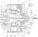
Fig. 1 is a sectional view of a vehicular power unit according to embodiment 1 of the invention;
fig. 2 is a side view of the vehicular power unit;
FIG. 3 is a sectional view taken along line III-III in FIG. 1;
fig. 4 is an exploded sectional view of the vehicular power unit;
fig. 5 is a sectional view showing a vehicular power unit according to another embodiment of the present invention;
fig. 6 is a sectional view showing a vehicular power unit according to another embodiment of the present invention;
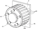
FIG. 7 is a perspective view of the vehicular power unit of FIG. 6;
fig. 8 is a perspective view showing a vehicular power unit according to another embodiment of the present invention;
fig. 9 is a sectional view showing a vehicular power unit according to another embodiment of the present invention;
fig. 10 is a side view of the vehicular power unit;
fig. 11 is a sectional view showing a vehicular power unit according to another embodiment of the present invention;
fig. 12 is a sectional view showing a vehicular power unit according to another embodiment of the present invention;
fig. 13 is a side view of the vehicular power unit;
fig. 14 is a block diagram showing a conceptual configuration of a vehicular system of a vehicle having either one of the vehicular power units;
fig. 15 is a power supply system diagram of an example of a vehicle mounted with the vehicle system;
fig. 16 is a diagram illustrating a conceptual configuration of a vehicle system of another vehicle having the vehicle power unit;
fig. 17 is a cross-sectional view of a conventional vehicular power unit;
fig. 18 is a cross-sectional view of another conventional vehicle power unit.
Detailed Description
[ embodiment 1 ]
A vehicle power unit according to an embodiment of the present invention will be described with reference to fig. 1 to 4.
Fig. 1 is a sectional view taken along line I-I of fig. 2. As shown in fig. 1, the vehicle power unit 1 includes: a wheel bearing 2; a bracket 24; a running motor 3 with a power generation function as an electric motor serving also as a generator. The vehicle power unit 1 includes an inner rotor type power generation function-equipped travel motor 3.
< bearing for wheel 2>
The wheel bearing 2 includes: an outer ring 4 as a rotating ring, double rows of rolling elements 6, a not-shown cage for holding the rolling elements 6, and an inner ring 5 as a stationary ring. The wheel bearing 2 is an angular contact ball bearing in which steel balls are used as rolling elements 6. Grease is sealed in the bearing space between the outer ring 4 and the inner ring 5. A direction along the rotation axis C1 of the wheel bearing 2 is referred to as a "bearing axis direction", and a direction perpendicular to the rotation axis C1 is referred to as a "bearing diameter direction".
The outer ring 4 has: an outer ring main body 4a having a double-row raceway surface formed thereon, and a wheel mounting flange 7 extending from an outer peripheral surface of the outer ring main body 4a to an outer diameter side. A plurality of hub bolts 13 are inserted into the wheel mounting flange 7. The wheel mounting flange 7 is mounted with the hub bolt 13 in a state where the brake rotor 12 and a wheel body of a wheel, not shown, are axially overlapped. A tire, not shown, is mounted on the outer periphery of the wheel body.
Instead of the hub bolts 13, threaded holes are formed in the flange surface of the outer ring 4, and the outer ring 4, the brake rotor 12, the wheel, and the tire are fixed from the outside by using wheel bolts (not shown).
In the present specification, in a state where the vehicle power unit 1 is mounted on a vehicle, a side closer to the vehicle outer side in the vehicle width direction is referred to as an outer side, and a side closer to the vehicle center in the vehicle width direction is referred to as an inner side.
The inner ring 5 has an inner ring main body 5a and a partial inner ring 5b fitted to the inner peripheral surface of the inner ring main body 5 a. The inner ring body 5a has an inner protrusion 5i protruding inward. The inner protrusion 5i is provided coaxially with the inner ring body 5a and integrally with the inner ring body 5a, and protrudes inward from the position where a part of the inner ring 5b is disposed. The above-mentioned "integral arrangement" means that the inner projecting portion 5i and the inner ring main body 5a are formed as a part or an entirety of a single body from a single material by, for example, forging, machining, or the like, instead of combining several elements.
The inner protruding portion 5i includes a fitting portion 9 and a male screw 11 in this order from the outside to the inside. The fitting portion 9 is a fitting portion of a bracket 24 described later, and is connected to the inner outer surface of the inner ring main body 5a by a step. The fitting portion 9 includes: a first fitting portion 9a having a diameter slightly smaller than the inner peripheral surface; and a second fitting portion 9b located outside the first fitting portion 9 a. The second fitting portion 9b forms a spline Sm that is fitted in a part of the holder base portion 24a of the holder 24 (a fitted portion 21 (fig. 4) described below). The spline Sm includes a plurality of spline teeth formed at fixed intervals in the circumferential direction, and the involute spline is preferable particularly from the viewpoint of suppressing vibration. The outer peripheral surface of the second fitting portion 9b, i.e., the outer diameter surface of the spline Sm, is formed to be smaller than the first fitting portion 9a and larger than the male screw 11.
< support 24>
The bracket 24 includes: a bracket base 24a fixed to the knuckle 8, the knuckle 8 serving as a chassis frame member of the vehicle; and a holder cylindrical portion 24b extending outward from an outer diameter side end of a large diameter portion (described later) of the holder base portion 24a. These holder base portions 24a and holder cylindrical portions 24b are formed coaxially and integrally. The holder base portion 24a and the holder cylindrical portion 24b may be formed of separate members. The bracket base 24a is interposed between the knuckle 8 and the inner ring 5, and the inner ring 5 is detachably fixed. The holder base 24a includes: a large diameter portion 24aa located on the outer side; and a small diameter portion 24ab connected to the inner surface of the large diameter portion 24aa and having a smaller diameter than the large diameter portion 24 aa.
As shown in fig. 4, the large diameter portion 24aa forms a fitting target portion 20, the fitting target portion 20 is fitted to the first fitting portion 9a, and the small diameter portion 24ab forms a fitting target portion 21, and the fitting target portion 21 is formed of spline grooves into which splines Sm as involute splines are fitted. The fitting of the first fitting portion 9a to the fitted portion 20 may be a clearance fitting or a pressing for the purpose of improving the accuracy of the axial center.
As shown in fig. 1 and 2, the knuckle 8 has a through hole 8b that allows the small-diameter portion 24ab to be fitted. The large diameter portion 24aa is formed with a plurality of circumferentially threaded holes, and the bracket base 24a is attached to the knuckle 8 by a plurality of bolts 22, which bolts 22 are screwed into these threaded holes. The bracket base 24a is fixed to the knuckle 8 in a state where the outer peripheral surface of the small diameter portion 24ab is fitted into the through hole 8b of the knuckle 8 and the inner surface of the large diameter portion 24aa is in contact with the outer surface 8a of the knuckle 8.
The inner side surface of the partial inner ring 5b is arranged to be in contact with and separable from the outer side of the large diameter portion 24 aa. The holder base 24a is formed with an insertion hole ha to allow insertion of the inner protrusion 5i therethrough. The insertion hole ha is formed by the fitted portions 20 and 21 (fig. 4). The first fitting portion 9a of the inner projecting portion 5i is fitted to the fitted portion 20 (fig. 4) of the large diameter portion 24aa, and the second fitting portion 9b of the inner projecting portion 5i is spline fitted to the fitted portion 21 (fig. 4) of the small diameter portion 24ab. The wheel bearing 2 is fixed to the bracket 24 by screwing the nut 25 to the male screw portion 11 to generate a predetermined torque value of the axial force at the bearing portion. The second fitting portion 9b of the inner ring main body 5a and the fitted portion 21 (fig. 4) of the bracket 24 are spline fitted to each other, and therefore, the rotation of the inner ring 5 and the vibration in the rotational direction can be suppressed.
< brake 17>
The brake 17 is a friction brake having a disc-shaped brake cylinder 12 and a brake caliper 16 (fig. 14). The brake cylinder 12 has a flat plate-like portion 12a and an outer peripheral portion 12b. The flat plate-like portion 12a is a ring-shaped flat plate-like member that overlaps the wheel mounting flange 7. The outer peripheral portion 12b includes a cylindrical portion 12ba extending in a cylindrical shape from an outer peripheral edge portion of the flat plate portion 12a to the inner side, and a flat plate portion 12bb extending in a flat plate shape from an inner end of the cylindrical portion 12ba to the outer diameter side. The brake caliper 16 (fig. 14) may be of any one of a hydraulic type and a mechanical type, or may be of an electric motor type.
< Motor 3> for traveling with Power Generation function.
As shown in fig. 1 and 3, the running motor 3 with a power generation function in this example is a running motor with a power generation function for running assistance, which generates power by turning of wheels and can rotationally drive the wheels by being supplied with power. The running motor 3 with a power generation function is an inner rotor type and includes: a stator 18 detachably mounted to an inner periphery of the holder cylindrical portion 24 b; and a rotor 19 mounted to the outer periphery of the outer ring body 4a on the inner periphery of the stator 18. The running motor 3 with a power generation function is a direct drive type, and the rotor 19 thereof is attached to the outer ring 4.
The power generation function-equipped travel motor 3 is provided radially inward of the inner diameter of the brake rotor 12 and is provided in the axial range between the wheel mounting flange 7 and the outer side surface 8a of the knuckle 8. The running Motor 3 with a power generation function is, for example, a Surface Magnet type Permanent Magnet Motor, namely, an SPM (Surface Permanent Magnet) Synchronous Motor (also referred to as SPMSM (Surface Permanent Magnet Synchronous Motor)).
Alternatively, the running Motor 3 with a power generation function is an IPM (Interior Permanent Magnet) Synchronous Motor (also referred to as IPMSM (Interior Permanent Magnet Synchronous Motor)). The other type of running Motor 3 with a power generation function can take various forms including a Switched reluctance Motor (SR Motor), an Induction Motor (IM Motor), and the like. In each type of motor, distributed windings and concentrated windings may be used as the winding type of the stator 18.
< stator 18>
The stator 18 includes an annular stator core 18a and a stator coil 18b, and the stator coil 18b and teeth of the stator core 18a are wound with an insulating material not shown. As the insulating material, a resin skeleton or the like can be used. The stator core 18a is made of, for example, electromagnetic steel plates, a pressed magnetic core, or an amorphous alloy. The stator core 18a is fitted to the inner circumferential surface of the holder cylindrical portion 24b of the holder 24. The stator core 18a is fixed to the inner circumferential surface of the bracket cylindrical portion 24b by crimping, adhesion, or restraint by another material. Although not shown in the drawings, a plurality of concave portions or convex portions are formed at predetermined intervals in the circumferential direction on the outer circumferential surface of the stator core 18a, and a plurality of convex portions or concave portions into which the concave portions or convex portions are fitted may be formed on the inner circumferential surface of the holder cylindrical portion 24 b. This can suppress the movement of the stator core 18 in the rotation direction.
< rotor 19>
The rotor 19 is disposed to face the stator core 18a radially inward. The rotor 19 includes: a cylindrical rotor core 19a fixed to the outer periphery of the outer ring body 4 a; and a permanent magnet 19b fixed to the outer periphery of the rotor core 19 a. The rotor core 19a is made of, for example, a soft magnetic material, is concentric with the outer ring body 4a, and is fixed to the outer ring body 4a by, for example, crimping, welding, or adhesion. A plurality of recesses are formed at regular intervals in the circumferential direction on the inner circumferential surface of the rotor core 19a, and permanent magnets 19b are fitted into the recesses and fixed by adhesion or the like.
< sealing Structure >
As shown in fig. 1, a seal member 23 is disposed between the outer inner peripheral surface of the bracket cylindrical member 24b and the outer peripheral surface of the wheel mounting flange 7, for preventing water and foreign matter from entering the inside of the power generation function drive motor 3 and the wheel bearing 2.
< sensor 27 for detecting rotation >
The vehicle power unit 1 is provided with a rotation detection sensor 27. The rotation detection sensor 27 detects a rotation angle or a rotation speed of the outer ring 4 with respect to the inner ring 5 to control the rotation of the running motor 3 with a power generation function. This rotational speed is synonymous with the number of revolutions per unit time. The rotation detection sensor 27 includes: the rotation detection sensor rotor 27a; a rotation detection sensor stator 27b that detects the rotation detection sensor rotor 27a; and an output cable 27c connected to the rotation detection sensor stator 27 b.
The rotation detection sensor stator 27b is fixed to the outer end of the inner race body 5a by a sensor fixing member 28. The rotation detection sensor rotor 27a is fixed to the outer end of the outer ring 4 by a bottomed cylindrical cover 29. The rotation detection sensor rotor 27a is fixed to the outer peripheral surface of a shaft portion protruding from the bottom of the cover 29 in the bearing shaft direction by fitting or the like. The cover 29 has water-proof properties and prevents water from entering the rotation detection sensor 27 and the bearing for the wheel.
A through hole 5aa serving as an external extraction means for extracting the output cable 27c to the outside (in this example, the inside of the knuckle 8) is formed inside the inner ring body 5 a. The through hole 5aa is formed along the axial center of the inner ring body 5a, and penetrates from the outer end to the inner end of the inner ring body 5 a. As the rotation detecting sensor 27, for example, a resolver (resolver) is applicable, but not limited to, and any form such as an encoder, a pulse coil, or a hall sensor may be adopted.
< wheel speed sensor Sa >
The wheel speed sensor Sa is a sensor for detecting the wheel rotation speed, and includes, for example, a magnetic encoder ring ER provided at the inner end of the outer ring 4 and a sensor portion (not shown) provided on the outer peripheral surface of a part of the inner ring 5b with a predetermined gap from the magnetic encoder ring ER. In this example, the wheel speed sensor Sa is provided separately from the rotation detection sensor 27, but the rotation detection sensor 27 may also function as the wheel speed sensor.
< method for separating bearing according to the present embodiment >
The procedure for replacing the wheel support bearing assembly 2 will be described with reference to fig. 4.
* The nut 25 is removed from the male screw 11 of the inner protrusion 5i.
* The wheel bearing 2 and the seal member 23 are pulled out from the bracket 24 along the bearing axis direction.
The assembly work is performed in the reverse order to the above.
< Effect >
According to the vehicle power unit 1 described above, the wheel bearing 2 is of the outer-ring rotation type in which the fixed ring is the inner ring 5 and the rotating ring is the outer ring 4. Further, the inner race 5 is detachably fixed to the bracket base 24a of the bracket 24. The stator 18 is detachably fixed to the inner periphery of a cylindrical holder cylindrical portion 24b extending from the holder base portion 24a to the outside. Therefore, when the wheel bearing 2 is replaced, the inner race 5 is disengaged from the bracket base 24a attached to the bogie 8, so that the components of the wheel bearing 2 and the like can be easily removed from the vehicle power unit 1. Then, a new assembly of the wheel bearing 2, etc. may be assembled in the reverse order to that described above. Further, since the stator 18 of the running motor 3 with a power generation function is fixed to the inner periphery of the bracket cylindrical portion 24b, a space occupied by the running motor 3 with a power generation function in the radial direction can be secured more than in the conventional structure in which a fastening portion is provided between the wheel bearing outer ring and the wheel bearing fixing member. Thus, a desired motor output can be obtained. When the running motor 3 with the power generation function is replaced, the wheel bearing 2 is simply detached from the vehicle power unit 1 so that the stator 18 can be detached from the inner periphery of the bracket cylindrical portion 24b without disassembling the bearing member and the like.
The power generation function-equipped traveling motor 3 is an inner rotor type in which the stator 18 is attached to the inner periphery of the bracket cylindrical portion 24b, and the rotor 19 is attached to the outer ring 4 on the inner periphery of the stator 18. Therefore, the heat generated in the stator 18 is transferred to the knuckle 8 through the stator 18, the holder cylindrical portion 24b, and the holder base portion 24a. Since the stator 18 does not contact the wheel bearing 2 in this manner, heat generated at the stator 18 is hardly transferred to the inside of the wheel bearing 2, and heat generated by the running motor 3 having a power generation function can be efficiently radiated to the knuckle 8 of the vehicle. The outer periphery of the holder cylindrical portion 24b in contact with the stator 18 is exposed to the outside air, and therefore, the heat generated by the running motor 3 with a power generation function can be radiated to the outside air very efficiently. This can prevent premature degradation of grease and the like inside the bearing.
Therefore, when the wheel bearing 2 or the like is replaced, the replacement can be performed as an independent unit, so that the replacement time and the replacement cost can be reduced, and the heat radiation performance of the stator 18 can be improved, thereby ensuring the reliability of the bearing.
The wheel support bearing 2 is configured to be detachably arranged in the bearing axis direction with respect to the support base 24a in a state where the support 24 is attached to the knuckle 8 and the stator 18 is provided on the support cylindrical portion 24 b. Therefore, when the wheel support bearing 2 is replaced, the entire vehicle power unit can be removed from the knuckle 8 at one time, and the components of the wheel support bearing 2 and the like can be pulled out from the vehicle power unit 1 in the bearing shaft direction. Therefore, the work load can be reduced.
< other embodiment >
Next, other embodiments and the like will be described. In the following description, the same reference numerals are given to parts corresponding to the items described earlier in the respective embodiments, and redundant description is omitted. When only a part of the structure is described, the other parts of the structure are the same as those described above unless otherwise specified. The same structure can achieve the same effect. Not only the combinations of the portions specifically described in the respective embodiments but also the embodiments may be partially combined with each other as long as there is no particular obstacle to the combinations.
Modification of embodiment 1: non-magnetic Material)
As shown in fig. 5, between the inner peripheral surface of the rotor 19 and the outer peripheral surface of the outer ring body 4a, a cylindrical member Rb made of a nonmagnetic material may be provided. In this case, it is possible to prevent the magnetic force generated by the rotor 19 from adversely affecting the wheel bearing 2.
Modification of embodiment 1: cooling tank
As shown in fig. 6 and 7, a heat radiating mechanism Hs is provided on the outer periphery of the holder cylindrical portion 24b to radiate heat generated by the power generation-function running motor 3 to the outside space. The heat sink Hs in this example includes a plurality of annular grooves (cooling grooves) 63 formed in the outer peripheral surface of the holder cylindrical portion 24 b. These annular grooves 63 are formed at regular intervals in the axial direction, for example. When the holder cylindrical portion 24b is viewed as being cut along a plane including the bearing axis direction, each annular groove 63 is in the form of a rectangular groove, but is not limited to the rectangular groove. The outer periphery of the bracket cylindrical portion 24b in contact with the stator 18 is exposed to the outside air, and therefore, the effect of radiating heat generated by the running motor 3 with a power generation function to the outside air is improved. In this case, if the heat radiation mechanism Hs is provided on the outer periphery of the holder cylindrical portion 24b, a greater heat radiation effect can be expected.
Modification of embodiment 1: other Cooling tanks
As shown in fig. 8, the heat radiating mechanism Hs may be configured to include a plurality of recesses (cooling grooves) 64 formed in the outer peripheral surface of the holder cylindrical portion 24 b. The plurality of concave portions 64 are formed at regular intervals in the circumferential direction on the outer circumferential surface of the holder cylindrical portion 24 b. Each recess 64 extends a predetermined distance in the bearing shaft direction from the outside to the inside on the outer peripheral surface of the bracket cylindrical portion 24 b. The cross section of each concave portion 64 is a rectangular groove shape when viewed in a plane perpendicular to the bearing axis direction with respect to the holder cylindrical portion 24b, but is not limited to the rectangular groove shape. In this case, the same effect as that of the heat dissipating mechanism Hs (fig. 6) described above can be achieved. The heat dissipation mechanism Hs is not limited to the examples of fig. 6 to 8, and may be changed into various shapes, so as to limit the range in which the brake rotor 12 (fig. 1) is not obstructed.
[ 2 nd embodiment ]
Fig. 9 is a cross-sectional view taken along line IX-IX of fig. 10. As shown in fig. 9 and 10, in the power unit 1 for a vehicle according to this embodiment, the inner ring 5 includes an inner ring body 5a and a partial inner ring 5b, and the partial inner ring 5b is fixed to an outer peripheral surface of the outer side of the inner ring body 5a by fastening of a nut 58. The inner ring body 5a in this example has an inner protrusion 5i protruding inward and an outer protrusion 5o protruding outward. A male screw portion 59 is formed at the tip end portion of the outer projecting portion 5o, and the nut 58 is screwed to the male screw portion 59, whereby a part of the inner ring 5b is fixed to the inner ring body 5a and bearing preload is provided. The inner projecting portion 5i is inserted into the insertion hole of the bracket base 24a, and the inner end surface of the inner ring body 5a is screwed to the male screw 11 of the inner projecting portion 5i by the nut 25 in a state of being in contact with the outer end surface of the bracket base 24a.
According to this configuration, the assembly of the wheel bearing 2 can be easily detached from the bracket base 24a in the axial direction by detaching the inner nut 25 from the male screw portion 11 of the inner protrusion 5i. Part of the inner ring 5b is fixed on the outer peripheral surface of the outer side of the inner ring body 5a by fastening with the nut 58 to provide a bearing preload, whereby a mechanism for providing the bearing preload and a fixing mechanism for fixing the inner ring 5 on the bracket base 24a can be separately constituted. Therefore, the bearing preload can be adjusted, and the reliability of the bearing is improved.
[ modification of embodiment 2: inner ring caulking shape
As shown in fig. 11, a part of the inner ring 5b is fixed to the outer peripheral surface of the inner ring body 5a by caulking of the caulking portion 60. In this case, the number of parts can be reduced and the axial length of the inner ring body 5a can be shortened as compared with the example of fig. 9 and 10.
[ 3 rd embodiment ]
Fig. 12 is a cross-sectional view taken along line XII-XII of fig. 13. As shown in fig. 12 and 13, the inner ring 5 in this example includes an inner ring body 5a and a partial inner ring 5b, and the outer peripheral surface of the partial inner ring 5b on the outer side of the inner ring body 5a is fixed by fastening with a nut 58. The inner end of the inner race body 5a has a flange portion 61 forming a screw hole 61a, and the flange portion 61 is detachably fixed to the bracket base portion 24a from the inside by a bolt 62. Although not shown in the drawings, a part of the inner ring 5b may be fixed to the outer circumferential surface of the outer side of the inner ring body 5a by caulking by a caulking portion 60 (see fig. 11).
According to this configuration, by detaching the bolts 62 from the flange plate 61 of the inner race body 5a, the assembly of the wheel bearing 2 can be easily detached from the bracket base 24a in the axial direction. Part of the inner ring 5b is fixed to the outer peripheral surface of the outer side of the inner ring body 5a by fastening or caulking of the nut 58 to provide bearing preload, and therefore, a mechanism for providing bearing preload and a fixing mechanism for fixing the inner ring 5 to the bracket base 24a can be separately constituted. Therefore, the bearing preload is easily adjusted, and the reliability of the bearing is improved.
< System for vehicle >
Fig. 14 is a block diagram showing a conceptual configuration of a vehicle system using the vehicle power unit 1 according to any one of the embodiments.
In this vehicle system, the vehicle power unit 1 includes a driven wheel 10 that is non-mechanically connected to a main drive source B In the vehicle, is mounted on the driven wheel 10 B The above. The wheel bearing 2 (fig. 1, etc.) in the vehicle power unit 1 supports the driven wheel 10 B The bearing of (1).
The main drive source 35 is an internal combustion engine such as a gasoline engine or a diesel engine, or a motor generator (electric motor), or a hybrid type drive source combining both. The "motor generator" is referred to as an electric motor capable of generating electric power by applying rotation thereto. In the illustrated example, the vehicle 30 has the front wheels as the drive wheels 10 A The rear wheel being a driven wheel 10 B The front wheel drive vehicle (1) is a hybrid vehicle (hereinafter, sometimes referred to as "HEV") in which the main drive source 35 has an internal combustion engine 35a and a drive wheel-side motor generator 35b.
Specifically, the motor generator 35b on the drive wheel side is in a medium-voltage drive light Hybrid (Mild Hybrid) form of 48V or the like. Hybrid power is roughly classified into strong hybrid power and light hybrid power, where light hybrid power is a form in which a main drive source is an internal combustion engine and running is assisted mainly by an electric motor at the time of start, acceleration, or the like, and in an EV (electric vehicle) mode, normal running cannot be performed for a long time even if it is temporarily performed, and is distinguished from strong hybrid power. Example of the figureThe internal combustion engine 35a is connected to the drive wheels 10 via a clutch 36 and a reduction gear 37 A The reduction gear 37 is connected to the drive shaft of (1) and a motor generator 35b on the drive wheel side is connected to the reduction gear.
The vehicle system includes: driven wheel 10 is carried out B The motor generator 3 of the rotationally driven travel assist generator, the respective control means 39 for controlling the motor generator, and the respective motor generator command means 45 provided in the upper ECU 40 and outputting commands for controlling the drive and regeneration of the respective control means 39. The motor generator 3 is connected to the power storage mechanism. The power storage mechanism may be a battery (storage battery), a capacitor, or the like, and its form and mounting position on the vehicle 30 are not limited. In the present embodiment, the power storage mechanism is the intermediate-voltage battery 49 out of the low-voltage battery 50 and the intermediate-voltage battery 49 mounted on the vehicle 30.
The motor generator 3 for the driven wheels is a direct drive motor without using a transmission. The motor generator 3 functions as a motor by supplying electric power, and also functions as a generator that converts kinetic energy of the vehicle 30 into electric power.
Since the motor generator 3 has the rotor 19 (fig. 1) attached to the outer ring 4 (fig. 1), if a current is applied to the motor generator 3, the outer ring 4 (fig. 1) is rotationally driven, and conversely, regenerative power is obtained by a load induced voltage at the time of power regeneration. The driving voltage or the regenerative voltage for driving the rotation of the motor generator 3 is 100V or less.
< control System of vehicle 30 >
The host ECU 40 is a mechanism for performing overall control of the vehicle 30, and includes a torque command generating mechanism 43. The torque command generating means 43 generates a torque command based on signals of operation amounts input from an accelerator operation means 56 such as an accelerator pedal and a brake operation means 57 such as a brake pedal. The vehicle 30 includes an internal combustion engine 35a as a main drive source 35 and a motor generator 35b on the drive wheel side, and has two driven wheels 10 driven respectively B 、10 B The upper ECU 40 is provided with the drive sources 35a, 35b, 3 according to the respective motor generators 3, 3A torque command distributing mechanism 44 for distributing the torque command.
A torque command for the internal combustion engine 35a is transmitted to the engine control means 47 and used for valve opening control and the like of the engine control means 47. The torque command for the drive wheel-side generator motor 35b is transmitted to the drive wheel-side motor/generator control mechanism 48 and executed. The torque commands for the motor generators 3, 3 on the driven wheel side are transmitted to the respective control mechanisms 39, 39. The portions of the torque command distribution mechanism 44 that are output to the respective control mechanisms 39, 39 are referred to as respective motor/generator command mechanisms 45. The respective motor/generator command means 45 also has the following functions: the signal of the operation amount of the brake operation means 57 is a torque command that is a command for the motor generator 3 to share the braking force of braking by regenerative braking, and is supplied to each self-control mechanism 39. A control means 68 for controlling the motor generator 3 is configured based on the motor generator command means 45 and the control means 39.
Each control mechanism 39 is an inverter device, and includes an inverter 41 that converts dc power of the medium-voltage battery 49 into three-phase ac voltage, and a control unit 42 that controls the output of the inverter 41 by PWM control or the like in accordance with the torque command or the like. The inverter 41 includes a bridge circuit (not shown) including semiconductor switching elements and the like, and a charging circuit (not shown) for charging the regenerative power of the motor generator 3 to the medium-voltage battery 49. The independent control mechanism 39 is provided separately from the two motor generators 3, but may be housed in a single case, and the two independent control mechanisms 39, 39 share the control unit 42.
Fig. 15 is a power supply system diagram as an example of a vehicle (fig. 14) equipped with the vehicle system. In the example of the figure, a low-voltage battery 50 and a medium-voltage battery 49 are provided as batteries, and the two batteries 49 and 50 are connected via a DC/DC converter 51. There are two motor generators 3, but one is shown as a representative. The driving wheel side motor generator 35b of fig. 14 is not shown in fig. 15, but is connected in parallel to the driven wheel side motor generator 3 in the medium electric power system. The low voltage load 52 is connected to the low voltage system, and the middle voltage load 53 is connected to the middle voltage system. There are a plurality of low voltage loads 52 and medium voltage loads 53, respectively, but one is represented as representative.
The low-voltage battery 50 is a battery generally used in various automobiles as a power source of a control system or the like, and is set to 12V or 24V, for example. The low-voltage load 52 includes basic components such as a starter motor of the internal combustion engine 35a, lamps, the upper ECU 40, and other ECUs (not shown). The low-voltage battery 50 may be referred to as an auxiliary battery for electric auxiliary equipment, and the medium-voltage battery 49 may be referred to as an auxiliary battery for an electric system.
The medium-voltage battery 49 has a voltage higher than the low-voltage battery 50 and lower than a high-voltage battery (100V or more, for example, about 200 to 400V) used for a strong hybrid vehicle or the like, and is a voltage at which the influence of an electric shock on the human body during operation does not become a problem, and a 48V battery used for a light hybrid in recent years is preferable. A medium-voltage battery 49 such as a 48V battery can be relatively easily mounted on a vehicle mounted with a conventional internal combustion engine, and as a light hybrid, fuel consumption can be reduced by power assist and regeneration based on electric power.
The intermediate voltage load 53 of the 48V system is the accessory member, and includes a power assist motor, an electric pump, an electric power steering device, a super charger, an air compressor, and the like, which are the drive wheel-side motor generator 35b. The load of the accessories constituted by the 48V system reduces the output of power assist compared with a high voltage (a hybrid vehicle or the like having 100V or more), but can reduce the risk of electric shock to the passengers or the maintenance worker. Since the insulating coating film of the electric wire can be made thin, the weight and volume of the electric wire can be reduced. In addition, since a large amount of electric power can be input and output at a current amount of less than 12V, the size of the motor or the generator can be reduced. This contributes to the fuel efficiency reduction effect of the vehicle.
The vehicle system is suitable for use as an accessory part of such a light hybrid vehicle, and is suitable for use as a power assist and electric power regeneration part. In contrast, in the light hybrid vehicle, CMG, GMG, a belt-driven starter motor (all not shown in the drawings) and the like are used, but they are affected by the efficiency of a transmission device, a reduction gear and the like because they assist or regenerate the power of an internal combustion engine or a power plant.
In contrast, the vehicle system of the present embodiment is mounted on the driven wheel 10 B Accordingly, the vehicle body is disconnected from the main drive source such as the internal combustion engine 35a and an electric motor (not shown), and the kinetic energy of the vehicle body can be directly utilized during power regeneration. In addition, when mounting CMG, GMG, a belt-driven starter motor, and the like, it is necessary to mount them in consideration of the design stage of the vehicle 30, and post-mounting is difficult.
In contrast, the drive wheel 10 accommodates the driven wheel B The motor generator 3 of the vehicle system in the vehicle can be mounted with the same number of steps as the replacement of the components even in the finished vehicle, and a 48V system can be configured for the finished vehicle having only the internal combustion engine 35 a. A conventional vehicle having only an internal combustion engine 35a is mounted with: the vehicle power unit 1 according to any one of the embodiments; and the medium-voltage battery 49 in which the driving voltage or the regenerative voltage of the battery as the motor generator is 100V or less, whereby a light hybrid vehicle can be formed without significantly modifying the vehicle. As in the example of fig. 14, another motor generator 35b for auxiliary driving may be mounted on the vehicle system of the embodiment. In this case, the amount of power assist and the amount of regenerative electric power for the vehicle 30 can be increased, which further contributes to a reduction in fuel consumption rate.
Fig. 16 shows a case where the vehicle power unit 1 of any of the embodiments described above is applied to the drive wheels 10 as the front wheels, respectively A And a driven wheel 10 as a rear wheel B Examples of (3). Driving wheel 10 A A main drive source 35 constituted by an internal combustion engine is driven via a clutch 36 and a reduction gear 37. In the front wheel drive vehicle, each drive wheel 10 A And a driven wheel 10 B The vehicle power unit 1 is provided for supporting and assisting driving. As described above, the vehicle power unit 1 can be applied not only to the driven wheel 10 B And can also be applied to the driving wheel 10 A 。
The vehicle system shown in fig. 14 has a function of generating electric power, but may be a system that does not perform rotational driving by power supply. The vehicle system is equipped with a wheel bearing device with a generator, which includes a generator 3 that does not also serve as a motor and a wheel bearing 2. The generator-equipped wheel support bearing has the same configuration as that of the vehicle power unit in any of the embodiments, except for the motor generator 3 that also serves as a motor.
According to the vehicle system in which the wheel support bearing with the generator is mounted, the regenerative electric power generated by the motor generator 3 is stored in the medium-voltage battery 49, and thereby the braking force can be generated. The braking performance can also be improved by using the mechanical brake operating mechanism 57 in combination or separately. When the function of generating power is limited as described above, the independent control means 39 may be configured not as an inverter but as an AC/DC converter (not shown). The AC/DC converter has a function of charging the regenerative power of the motor generator 3 to the medium-voltage battery 49 by converting the three-phase AC voltage to the DC voltage, and is easy to control and can be downsized compared to an inverter.
As described above, the preferred embodiments have been described with reference to the drawings, but various additions, modifications, and deletions can be made within the scope not departing from the spirit of the present invention. Therefore, such a structure is also included in the scope of the present invention.
Description of the symbols
1, 8230, 2, 8230, 3, 8230, a motor for driving with power generation, 4, 8230, an outer ring, 5, 8230, an inner ring, 5a, 8230, an inner ring body, 5b, 8230, a partial inner ring, 5i, 8230, an inner protrusion, 6, 8230, a rolling element, 7, 8230, a wheel mounting flange, 8, 8230, a steering joint chassis frame component, 11, 8230, an outer thread portion, 18, 8230, a stator, 8230, 19 \8230, rotor 24 \8230, 8230, support 24a \8230, 8230, support base 24b \8230, 8230, support cylinder 25, 58 \8230, rotation detection sensor 27a 8230, rotor 8230, rotation detection sensor rotor, 27b \8230;, rotation detection sensor stator, 27c \8230;, 8230, output cable, 61 \8230;, flange portion, 62 \8230;, 8230, bolt, hs \8230;, 823030, heat dissipation mechanism, rb \8230, 8230, cylinder component, sm \8230, 8230, splines.
Claims (11)
1. A power unit for a vehicle, comprising: a wheel bearing having an inner ring as a stationary ring and an outer ring as a rotating ring rotatably supported on the inner ring by rolling elements, the wheel bearing having a wheel mounting flange at an outer end of the outer ring, the wheel mounting flange being used for mounting a wheel of a vehicle; and a motor capable of rotationally driving the rotating ring, characterized in that,
the vehicle power unit includes a bracket attached to a chassis frame member of the vehicle, and the bracket includes: a bracket base interposed between the chassis frame member and the inner ring, the inner ring being detachably fixed to the bracket base; and a cylindrical holder cylindrical portion extending outward from the holder base portion,
the motor includes: a stator detachably attached to an inner circumference of the holder cylindrical portion; and a rotor mounted to the outer ring at an inner periphery of the stator.
2. The vehicle power unit according to claim 1, wherein the wheel support bearing is detachably configured in a bearing axis direction with respect to the bracket base portion in a state where the stator is provided in the bracket cylindrical portion while the bracket is attached to the chassis frame member.
3. The vehicle power unit according to claim 1 or 2, wherein the inner ring includes an inner ring body and a partial inner ring, the partial inner ring is fitted to an inner peripheral surface of the inner ring body, the inner ring body has an inner protruding portion that protrudes inward, a male screw portion is formed at a tip end portion thereof, an insertion hole allowing insertion of the inner protruding portion is formed in the bracket base, the inner protruding portion is inserted into the insertion hole of the bracket base, and a nut is provided that is screwed to the male screw portion of the inner protruding portion in a state where an inner end surface of the partial inner ring is in contact with an outer side surface of the bracket base.
4. The vehicle power unit according to claim 1 or 2, wherein the inner ring includes an inner ring body and a partial inner ring fixed to an outer peripheral surface of an outer side of the inner ring body by fastening or caulking with a nut, the inner ring body includes an inner protruding portion protruding inward and having a male screw portion formed at a tip end portion thereof, the bracket base includes an insertion hole allowing insertion of the inner protruding portion therethrough, the inner protruding portion is inserted into the insertion hole of the bracket base, and a nut is provided to be screwed with the male screw portion of the inner protruding portion in a state where an inner end surface of the inner ring body is in contact with an outer side surface of the bracket base.
5. The vehicle power unit according to claim 1 or claim 2, wherein the inner ring includes an inner ring body and a partial inner ring fixed to an outer peripheral surface of an outer side of the inner ring body by nut fastening or caulking, an inner end of the inner ring body has a flange portion formed with a screw hole, and the flange portion is detachably fixed to the bracket base portion from an inner side by a bolt.
6. The vehicular power unit according to claim 3 or 4, wherein a spline is provided on the inner protruding portion through which the insertion hole of the bracket base is inserted, so as to prevent relative rotation with respect to the bracket base.
7. The vehicle power device according to any one of claims 1 to 6, wherein a rotation detection sensor is provided in the wheel bearing to detect a rotation speed of the outer ring relative to the inner ring, the rotation detection sensor including: the rotation detecting sensor comprises a rotation detecting sensor rotor arranged at the outer side end of the outer ring, and a rotation detecting sensor stator arranged at the outer side end of the inner ring and used for detecting the rotation detecting sensor rotor, and the rotation detecting sensor stator is provided with an external taking-out mechanism used for taking out an output cable of the rotation detecting sensor to the outside.
8. The vehicle power unit according to claim 7, wherein the rotation detection sensor also functions as a wheel speed sensor.
9. The vehicular power unit according to any one of claims 1 to 8, wherein a cylindrical member made of a nonmagnetic material is provided between an inner peripheral surface of the rotor and an outer peripheral surface of the outer ring.
10. The vehicular power unit according to any one of claims 1 to 9, wherein a heat radiation mechanism is provided on an outer periphery of the bracket cylindrical portion to radiate heat generated by the electric motor to an external space.
11. A wheel bearing with a generator, comprising: a wheel bearing having an inner ring serving as a stationary ring and an outer ring serving as a rotating ring rotatably supported by rolling elements, the wheel bearing having a wheel mounting flange at an outer end of the outer ring for mounting a wheel of a vehicle; and a generator for generating power according to the rotation of the rotating ring,
the wheel bearing with generator has a bracket attached to a chassis frame member of the vehicle, and the bracket has: a bracket base interposed between the chassis frame member and the inner ring, the inner ring being detachably fixed to the bracket base; and a cylindrical holder cylindrical portion extending outward from the holder base portion,
the generator includes: a stator detachably attached to an inner circumference of the holder cylindrical portion; and a rotor mounted to the outer ring at an inner periphery of the stator.
Applications Claiming Priority (3)
| Application Number | Priority Date | Filing Date | Title |
|---|---|---|---|
| JP2020099184A JP7349961B2 (en) | 2020-06-08 | 2020-06-08 | Bearings for vehicle power units and wheels with generators |
| JP2020-099184 | 2020-06-08 | ||
| PCT/JP2021/021403 WO2021251300A1 (en) | 2020-06-08 | 2021-06-04 | Vehicle power device and vehicle bearing with power generator |
Publications (1)
| Publication Number | Publication Date |
|---|---|
| CN115697742A true CN115697742A (en) | 2023-02-03 |
Family
ID=78846249
Family Applications (1)
| Application Number | Title | Priority Date | Filing Date |
|---|---|---|---|
| CN202180041113.4A Pending CN115697742A (en) | 2020-06-08 | 2021-06-04 | Power unit for vehicle and wheel bearing with generator |
Country Status (5)
| Country | Link |
|---|---|
| US (1) | US20230098893A1 (en) |
| EP (1) | EP4163139A1 (en) |
| JP (1) | JP7349961B2 (en) |
| CN (1) | CN115697742A (en) |
| WO (1) | WO2021251300A1 (en) |
Family Cites Families (8)
| Publication number | Priority date | Publication date | Assignee | Title |
|---|---|---|---|---|
| JPH05278476A (en) * | 1992-04-06 | 1993-10-26 | Toyota Motor Corp | Wheel motor for electric vehicle |
| JP2004190736A (en) * | 2002-12-10 | 2004-07-08 | Ntn Corp | Bearing device for wheel |
| JP5110854B2 (en) | 2006-11-17 | 2012-12-26 | Ntn株式会社 | Wheel bearing device with in-wheel motor built-in sensor |
| JP4970970B2 (en) | 2007-02-01 | 2012-07-11 | 東洋電機製造株式会社 | Jig for in-wheel motor unit |
| JP5278476B2 (en) | 2011-03-30 | 2013-09-04 | Tdk株式会社 | Multilayer capacitor |
| JP7079582B2 (en) | 2016-09-21 | 2022-06-02 | Ntn株式会社 | Wheel bearing device with auxiliary power unit and its auxiliary power unit |
| JP2019050712A (en) * | 2017-09-08 | 2019-03-28 | Ntn株式会社 | Power arrangement for vehicle and vehicle having the same |
| JP7066520B2 (en) | 2018-05-21 | 2022-05-13 | Ntn株式会社 | Bearings for vehicle power units and wheels with generators |
-
2020
- 2020-06-08 JP JP2020099184A patent/JP7349961B2/en active Active
-
2021
- 2021-06-04 WO PCT/JP2021/021403 patent/WO2021251300A1/en unknown
- 2021-06-04 EP EP21822985.4A patent/EP4163139A1/en active Pending
- 2021-06-04 CN CN202180041113.4A patent/CN115697742A/en active Pending
-
2022
- 2022-12-05 US US18/074,635 patent/US20230098893A1/en active Pending
Also Published As
| Publication number | Publication date |
|---|---|
| JP2021192999A (en) | 2021-12-23 |
| JP7349961B2 (en) | 2023-09-25 |
| US20230098893A1 (en) | 2023-03-30 |
| WO2021251300A1 (en) | 2021-12-16 |
| EP4163139A1 (en) | 2023-04-12 |
Similar Documents
| Publication | Publication Date | Title |
|---|---|---|
| JP7156787B2 (en) | Wheel bearing device and vehicle equipped with this wheel bearing device | |
| EP3798035B1 (en) | Vehicle power unit and vehicle wheel bearing with generator | |
| JP2018052482A (en) | Bearing device for wheel with auxiliary power unit and auxiliary power unit | |
| US20210075289A1 (en) | Motor, vehicle power unit with motor, generator, vehicle wheel bearing with generator | |
| WO2021251299A1 (en) | Vehicle power device and wheel bearing with generator | |
| US11634021B2 (en) | Power device for vehicles | |
| EP3922482A1 (en) | Vehicle power device and wheel bearing device equipped with generator | |
| WO2019138965A1 (en) | Wheel bearing apparatus and vehicle provided with wheel bearing apparatus | |
| JP6997571B2 (en) | Bearing device for wheels with generator | |
| JP2019075976A (en) | Vehicle power device and generator-equipped wheel bearing device | |
| WO2019078216A1 (en) | Vehicle power device and wheel bearing device with generator | |
| WO2021251300A1 (en) | Vehicle power device and vehicle bearing with power generator | |
| WO2019049973A1 (en) | Bearing device for vehicle wheel, and vehicle provided with bearing device for vehicle wheel | |
| JP2019048555A (en) | Bearing device for wheel with generator and vehicle provided with bearing device for wheel with generator | |
| JP2019049314A (en) | Bearing device for wheel with power generator and vehicle provided with bearing device for wheel with power generator |
Legal Events
| Date | Code | Title | Description |
|---|---|---|---|
| PB01 | Publication | ||
| PB01 | Publication | ||
| SE01 | Entry into force of request for substantive examination | ||
| SE01 | Entry into force of request for substantive examination |