CN115667574A - Vapor deposition apparatus and method of coating a substrate in a vacuum chamber - Google Patents
Vapor deposition apparatus and method of coating a substrate in a vacuum chamber Download PDFInfo
- Publication number
- CN115667574A CN115667574A CN202180039788.5A CN202180039788A CN115667574A CN 115667574 A CN115667574 A CN 115667574A CN 202180039788 A CN202180039788 A CN 202180039788A CN 115667574 A CN115667574 A CN 115667574A
- Authority
- CN
- China
- Prior art keywords
- heatable
- shield
- vapor
- substrate
- deposition apparatus
- Prior art date
- Legal status (The legal status is an assumption and is not a legal conclusion. Google has not performed a legal analysis and makes no representation as to the accuracy of the status listed.)
- Pending
Links
Images


Classifications
-
- C—CHEMISTRY; METALLURGY
- C23—COATING METALLIC MATERIAL; COATING MATERIAL WITH METALLIC MATERIAL; CHEMICAL SURFACE TREATMENT; DIFFUSION TREATMENT OF METALLIC MATERIAL; COATING BY VACUUM EVAPORATION, BY SPUTTERING, BY ION IMPLANTATION OR BY CHEMICAL VAPOUR DEPOSITION, IN GENERAL; INHIBITING CORROSION OF METALLIC MATERIAL OR INCRUSTATION IN GENERAL
- C23C—COATING METALLIC MATERIAL; COATING MATERIAL WITH METALLIC MATERIAL; SURFACE TREATMENT OF METALLIC MATERIAL BY DIFFUSION INTO THE SURFACE, BY CHEMICAL CONVERSION OR SUBSTITUTION; COATING BY VACUUM EVAPORATION, BY SPUTTERING, BY ION IMPLANTATION OR BY CHEMICAL VAPOUR DEPOSITION, IN GENERAL
- C23C14/00—Coating by vacuum evaporation, by sputtering or by ion implantation of the coating forming material
- C23C14/22—Coating by vacuum evaporation, by sputtering or by ion implantation of the coating forming material characterised by the process of coating
- C23C14/24—Vacuum evaporation
-
- B—PERFORMING OPERATIONS; TRANSPORTING
- B05—SPRAYING OR ATOMISING IN GENERAL; APPLYING FLUENT MATERIALS TO SURFACES, IN GENERAL
- B05B—SPRAYING APPARATUS; ATOMISING APPARATUS; NOZZLES
- B05B12/00—Arrangements for controlling delivery; Arrangements for controlling the spray area
- B05B12/16—Arrangements for controlling delivery; Arrangements for controlling the spray area for controlling the spray area
-
- B—PERFORMING OPERATIONS; TRANSPORTING
- B05—SPRAYING OR ATOMISING IN GENERAL; APPLYING FLUENT MATERIALS TO SURFACES, IN GENERAL
- B05C—APPARATUS FOR APPLYING FLUENT MATERIALS TO SURFACES, IN GENERAL
- B05C21/00—Accessories or implements for use in connection with applying liquids or other fluent materials to surfaces, not provided for in groups B05C1/00 - B05C19/00
- B05C21/005—Masking devices
-
- C—CHEMISTRY; METALLURGY
- C23—COATING METALLIC MATERIAL; COATING MATERIAL WITH METALLIC MATERIAL; CHEMICAL SURFACE TREATMENT; DIFFUSION TREATMENT OF METALLIC MATERIAL; COATING BY VACUUM EVAPORATION, BY SPUTTERING, BY ION IMPLANTATION OR BY CHEMICAL VAPOUR DEPOSITION, IN GENERAL; INHIBITING CORROSION OF METALLIC MATERIAL OR INCRUSTATION IN GENERAL
- C23C—COATING METALLIC MATERIAL; COATING MATERIAL WITH METALLIC MATERIAL; SURFACE TREATMENT OF METALLIC MATERIAL BY DIFFUSION INTO THE SURFACE, BY CHEMICAL CONVERSION OR SUBSTITUTION; COATING BY VACUUM EVAPORATION, BY SPUTTERING, BY ION IMPLANTATION OR BY CHEMICAL VAPOUR DEPOSITION, IN GENERAL
- C23C14/00—Coating by vacuum evaporation, by sputtering or by ion implantation of the coating forming material
- C23C14/04—Coating on selected surface areas, e.g. using masks
- C23C14/042—Coating on selected surface areas, e.g. using masks using masks
-
- C—CHEMISTRY; METALLURGY
- C23—COATING METALLIC MATERIAL; COATING MATERIAL WITH METALLIC MATERIAL; CHEMICAL SURFACE TREATMENT; DIFFUSION TREATMENT OF METALLIC MATERIAL; COATING BY VACUUM EVAPORATION, BY SPUTTERING, BY ION IMPLANTATION OR BY CHEMICAL VAPOUR DEPOSITION, IN GENERAL; INHIBITING CORROSION OF METALLIC MATERIAL OR INCRUSTATION IN GENERAL
- C23C—COATING METALLIC MATERIAL; COATING MATERIAL WITH METALLIC MATERIAL; SURFACE TREATMENT OF METALLIC MATERIAL BY DIFFUSION INTO THE SURFACE, BY CHEMICAL CONVERSION OR SUBSTITUTION; COATING BY VACUUM EVAPORATION, BY SPUTTERING, BY ION IMPLANTATION OR BY CHEMICAL VAPOUR DEPOSITION, IN GENERAL
- C23C14/00—Coating by vacuum evaporation, by sputtering or by ion implantation of the coating forming material
- C23C14/06—Coating by vacuum evaporation, by sputtering or by ion implantation of the coating forming material characterised by the coating material
- C23C14/14—Metallic material, boron or silicon
- C23C14/16—Metallic material, boron or silicon on metallic substrates or on substrates of boron or silicon
-
- C—CHEMISTRY; METALLURGY
- C23—COATING METALLIC MATERIAL; COATING MATERIAL WITH METALLIC MATERIAL; CHEMICAL SURFACE TREATMENT; DIFFUSION TREATMENT OF METALLIC MATERIAL; COATING BY VACUUM EVAPORATION, BY SPUTTERING, BY ION IMPLANTATION OR BY CHEMICAL VAPOUR DEPOSITION, IN GENERAL; INHIBITING CORROSION OF METALLIC MATERIAL OR INCRUSTATION IN GENERAL
- C23C—COATING METALLIC MATERIAL; COATING MATERIAL WITH METALLIC MATERIAL; SURFACE TREATMENT OF METALLIC MATERIAL BY DIFFUSION INTO THE SURFACE, BY CHEMICAL CONVERSION OR SUBSTITUTION; COATING BY VACUUM EVAPORATION, BY SPUTTERING, BY ION IMPLANTATION OR BY CHEMICAL VAPOUR DEPOSITION, IN GENERAL
- C23C14/00—Coating by vacuum evaporation, by sputtering or by ion implantation of the coating forming material
- C23C14/22—Coating by vacuum evaporation, by sputtering or by ion implantation of the coating forming material characterised by the process of coating
- C23C14/54—Controlling or regulating the coating process
-
- C—CHEMISTRY; METALLURGY
- C23—COATING METALLIC MATERIAL; COATING MATERIAL WITH METALLIC MATERIAL; CHEMICAL SURFACE TREATMENT; DIFFUSION TREATMENT OF METALLIC MATERIAL; COATING BY VACUUM EVAPORATION, BY SPUTTERING, BY ION IMPLANTATION OR BY CHEMICAL VAPOUR DEPOSITION, IN GENERAL; INHIBITING CORROSION OF METALLIC MATERIAL OR INCRUSTATION IN GENERAL
- C23C—COATING METALLIC MATERIAL; COATING MATERIAL WITH METALLIC MATERIAL; SURFACE TREATMENT OF METALLIC MATERIAL BY DIFFUSION INTO THE SURFACE, BY CHEMICAL CONVERSION OR SUBSTITUTION; COATING BY VACUUM EVAPORATION, BY SPUTTERING, BY ION IMPLANTATION OR BY CHEMICAL VAPOUR DEPOSITION, IN GENERAL
- C23C14/00—Coating by vacuum evaporation, by sputtering or by ion implantation of the coating forming material
- C23C14/22—Coating by vacuum evaporation, by sputtering or by ion implantation of the coating forming material characterised by the process of coating
- C23C14/56—Apparatus specially adapted for continuous coating; Arrangements for maintaining the vacuum, e.g. vacuum locks
- C23C14/562—Apparatus specially adapted for continuous coating; Arrangements for maintaining the vacuum, e.g. vacuum locks for coating elongated substrates
-
- C—CHEMISTRY; METALLURGY
- C23—COATING METALLIC MATERIAL; COATING MATERIAL WITH METALLIC MATERIAL; CHEMICAL SURFACE TREATMENT; DIFFUSION TREATMENT OF METALLIC MATERIAL; COATING BY VACUUM EVAPORATION, BY SPUTTERING, BY ION IMPLANTATION OR BY CHEMICAL VAPOUR DEPOSITION, IN GENERAL; INHIBITING CORROSION OF METALLIC MATERIAL OR INCRUSTATION IN GENERAL
- C23C—COATING METALLIC MATERIAL; COATING MATERIAL WITH METALLIC MATERIAL; SURFACE TREATMENT OF METALLIC MATERIAL BY DIFFUSION INTO THE SURFACE, BY CHEMICAL CONVERSION OR SUBSTITUTION; COATING BY VACUUM EVAPORATION, BY SPUTTERING, BY ION IMPLANTATION OR BY CHEMICAL VAPOUR DEPOSITION, IN GENERAL
- C23C14/00—Coating by vacuum evaporation, by sputtering or by ion implantation of the coating forming material
- C23C14/22—Coating by vacuum evaporation, by sputtering or by ion implantation of the coating forming material characterised by the process of coating
- C23C14/56—Apparatus specially adapted for continuous coating; Arrangements for maintaining the vacuum, e.g. vacuum locks
- C23C14/564—Means for minimising impurities in the coating chamber such as dust, moisture, residual gases
-
- H—ELECTRICITY
- H01—ELECTRIC ELEMENTS
- H01J—ELECTRIC DISCHARGE TUBES OR DISCHARGE LAMPS
- H01J37/00—Discharge tubes with provision for introducing objects or material to be exposed to the discharge, e.g. for the purpose of examination or processing thereof
- H01J37/32—Gas-filled discharge tubes
- H01J37/32431—Constructional details of the reactor
- H01J37/32733—Means for moving the material to be treated
- H01J37/32752—Means for moving the material to be treated for moving the material across the discharge
-
- H—ELECTRICITY
- H01—ELECTRIC ELEMENTS
- H01M—PROCESSES OR MEANS, e.g. BATTERIES, FOR THE DIRECT CONVERSION OF CHEMICAL ENERGY INTO ELECTRICAL ENERGY
- H01M10/00—Secondary cells; Manufacture thereof
- H01M10/05—Accumulators with non-aqueous electrolyte
- H01M10/052—Li-accumulators
-
- H—ELECTRICITY
- H01—ELECTRIC ELEMENTS
- H01M—PROCESSES OR MEANS, e.g. BATTERIES, FOR THE DIRECT CONVERSION OF CHEMICAL ENERGY INTO ELECTRICAL ENERGY
- H01M4/00—Electrodes
- H01M4/02—Electrodes composed of, or comprising, active material
- H01M4/04—Processes of manufacture in general
- H01M4/0402—Methods of deposition of the material
- H01M4/0421—Methods of deposition of the material involving vapour deposition
- H01M4/0423—Physical vapour deposition
-
- H—ELECTRICITY
- H01—ELECTRIC ELEMENTS
- H01M—PROCESSES OR MEANS, e.g. BATTERIES, FOR THE DIRECT CONVERSION OF CHEMICAL ENERGY INTO ELECTRICAL ENERGY
- H01M4/00—Electrodes
- H01M4/02—Electrodes composed of, or comprising, active material
- H01M4/13—Electrodes for accumulators with non-aqueous electrolyte, e.g. for lithium-accumulators; Processes of manufacture thereof
- H01M4/139—Processes of manufacture
- H01M4/1395—Processes of manufacture of electrodes based on metals, Si or alloys
-
- Y—GENERAL TAGGING OF NEW TECHNOLOGICAL DEVELOPMENTS; GENERAL TAGGING OF CROSS-SECTIONAL TECHNOLOGIES SPANNING OVER SEVERAL SECTIONS OF THE IPC; TECHNICAL SUBJECTS COVERED BY FORMER USPC CROSS-REFERENCE ART COLLECTIONS [XRACs] AND DIGESTS
- Y02—TECHNOLOGIES OR APPLICATIONS FOR MITIGATION OR ADAPTATION AGAINST CLIMATE CHANGE
- Y02E—REDUCTION OF GREENHOUSE GAS [GHG] EMISSIONS, RELATED TO ENERGY GENERATION, TRANSMISSION OR DISTRIBUTION
- Y02E60/00—Enabling technologies; Technologies with a potential or indirect contribution to GHG emissions mitigation
- Y02E60/10—Energy storage using batteries
Abstract
The present disclosure describes a vapor deposition apparatus. The vapor deposition apparatus includes a substrate support for supporting a substrate to be coated; a vapor source having a plurality of nozzles for directing vapor through the vapor propagation space toward the substrate support; and a heatable shield extending from the vapor source toward the substrate support. A heatable shield at least partially surrounds the vapor propagation space and includes an edge exclusion portion for masking an uncoated area of the substrate. The substrate support may be a rotatable drum having a curved drum surface, and the vapor deposition apparatus may be configured to move the substrate on the curved drum surface in a circumferential direction past the vapor source.
Description
Technical Field
Various embodiments of the present disclosure relate to substrate coating by thermal evaporation in a vacuum chamber. Embodiments of the present disclosure also relate to depositing one or more coated strips (strip) on a flexible substrate (e.g., on a flexible metal foil) by evaporation. In particular, embodiments relate to lithium deposition on flexible foils, for example for the manufacture of lithium batteries. In particular, embodiments relate to a vapor deposition apparatus, a method for coating a substrate in a vacuum chamber, and a method of installing a vapor deposition apparatus.
Background
Various techniques for deposition on a substrate are known, such as Chemical Vapor Deposition (CVD) and Physical Vapor Deposition (PVD). For high deposition rate deposition, thermal evaporation may be used as the PVD process. For thermal evaporation, a source material is heated to generate a vapor, which may be deposited on, for example, a substrate. Increasing the temperature of the heated source material increases the vapor concentration and may promote a high deposition rate. The temperature at which a high deposition rate is achieved depends on the physical properties of the source material, such as vapor pressure as a function of temperature, and the physical limitations of the substrate, such as melting point.
For example, a material to be deposited on a substrate may be heated in a crucible to generate a vapor at an elevated vapor pressure. The vapor may be delivered from a crucible to a heated vapor distributor having a plurality of nozzles. The vapor may be directed by one or more nozzles onto a substrate in a coating space (e.g., in a vacuum chamber).
Deposition of metal (e.g., lithium) by evaporation on a flexible substrate (e.g., on a copper substrate) can be used to fabricate batteries, such as lithium batteries. For example, a lithium layer can be deposited on a thin flexible substrate to make the anode of a battery. After assembling the anode layer stack and the cathode layer stack, optionally with electrolyte and/or separator in between, the manufactured layer arrangement (arrangement) may be rolled up or otherwise stacked to produce a lithium battery.
Surfaces of the component, such as vacuum chamber walls of a vacuum chamber, may be exposed to the vapor and may be coated. Frequent maintenance to remove condensate is impractical for high volume production, such as coil coating on foil (web coating). Furthermore, if parts of the vacuum chamber other than the substrate are coated, expensive coating materials may be wasted.
Furthermore, it is often difficult to deposit a layer with well-defined sharp (sharp) edges on a substrate by evaporation, especially if the vapor is a metal vapor and the nozzle is to provide a large plume divergence (plume divergence). The masking effect and material condensation on the shield arrangement may result in an undefined layer edge on the substrate and/or material deposition on areas of the substrate that are to be kept free of coating material.
It would therefore be beneficial to have a vapor deposition apparatus and method for coating a substrate in a vacuum chamber that can reduce maintenance cycles and at the same time enable sharp edges of the coating on the substrate and coating-free edges of the substrate even if the substrate is flexible or curved. Furthermore, the utilization of the source material is advantageously increased. Therefore, the production cost can be reduced and the quality of the layer can be improved.
Disclosure of Invention
In view of this, a vapor deposition apparatus, a method of coating a substrate in a vacuum chamber and a method of mounting a vapor deposition apparatus according to the independent claims are provided. Other aspects, advantages, and features of the present disclosure will be apparent from the description and drawings.
According to one aspect, a vapor deposition apparatus is provided. The vapor deposition apparatus includes: a substrate support for supporting a substrate to be coated; a vapor source having a plurality of nozzles for directing vapor through the vapor propagation space toward the substrate support; and a heatable shield extending from the vapor source toward the substrate support and at least partially surrounding the vapor propagation space, wherein the heatable shield includes an edge exclusion portion for masking (mask) areas of the substrate that are not to be coated.
The edge exclusion portion may be disposed a small distance from, i.e., not in contact with, the substrate support such that the substrate support, along with a substrate supported on the substrate support, may move past the heatable shield and past the vapor source during vapor deposition. In particular, the heat shield may be mounted at the vapor source and protrude toward the substrate support such that the edge exclusion portion of the heatable shield is maintained at a close distance (e.g., 2mm or less) from the substrate support.
According to one aspect, a vapor deposition apparatus is provided. The vapor deposition apparatus includes: a substrate support for supporting a substrate to be coated, wherein the substrate support is a rotatable drum having a curved drum (drum) surface; a vapor source having a plurality of nozzles for directing vapor through the vapor propagation space toward the curved drum surface; and a heatable shield extending from the vapor source toward the curved drum surface and at least partially surrounding the vapor propagation space, the heatable shield defining a coating window on the curved drum surface.
According to one aspect, a method for coating a substrate in a vacuum chamber is provided. The method comprises the following steps: moving the substrate in a circumferential direction past a vapor source on a curved roller surface of a rotatable roller; directing vapor from the vapor source through a vapor propagation space toward the substrate supported on the curved platen surface; and heating a heatable shield extending from the vapor source toward the curved drum surface and at least partially surrounding the vapor propagation space.
According to one aspect, a method for coating a substrate in a vacuum chamber is provided. The method comprises the following steps: supporting a substrate on a substrate support; directing vapor from a vapor source through a vapor propagation space toward a substrate supported on a substrate support; heating a heatable shield at least partially surrounding the vapor propagation space; and masking the uncoated area of the substrate with an edge exclusion portion of the heatable shield.
In the method described in the present disclosure, the heatable shield is heated to a temperature (also referred to as "operating temperature" in the present disclosure) for preventing or at least reducing condensation of vapor on the heatable shield. Conversely, vapor that strikes the heatable shield may be re-evaporated and/or reflected. The "heatable shield" may also be referred to as a "temperature controlled shield" in this disclosure, as the temperature of the heatable shield may be set to a predetermined operating temperature during vapor deposition, thereby reducing or preventing vapor condensation on the heatable shield.
According to one aspect, a method of installing a vapor deposition apparatus is provided. The method comprises the following steps: providing a rotatable drum having a curved drum surface for supporting the substrate and a steam source for directing steam towards the curved drum surface; the heatable shield is mounted such that the heatable shield extends from the vapor source toward the curved drum surface and defines a coating window, wherein the heatable shield includes an edge exclusion portion extending along and following a curvature of the curved drum surface in a circumferential direction.
According to an aspect, there is provided a method of manufacturing a coated substrate in a vapor deposition apparatus according to any one of the embodiments of the present disclosure. The method comprises the following steps: supporting a substrate on a substrate support of a vapor deposition apparatus; directing vapor from a vapor source of the vapor deposition apparatus toward the substrate to deposit one or more coated strips on the substrate.
Embodiments are also directed to apparatuses for performing the disclosed methods and include means for performing each of the described method aspects. These method aspects may be performed by hardware components, a computer programmed by appropriate software, by any combination of the two, or in any other manner. Further, embodiments according to the present disclosure also relate to methods of manufacturing the devices and products, and methods of operating the devices. The various embodiments include method aspects for performing each function of the device.
Drawings
So that the manner in which the above recited features of the present disclosure can be understood in detail, a more particular description of the disclosure, briefly summarized above, may be had by reference to embodiments. The drawings relate to various embodiments of the present disclosure and are described as follows:
FIG. 1 is a schematic cross-sectional view of a vapor deposition apparatus of various embodiments of the present disclosure;
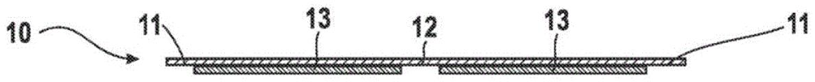
FIG. 2 shows a schematic cross-sectional view of a coated substrate made in accordance with various embodiments of the present disclosure;
FIG. 3 shows a schematic view of a vapor deposition apparatus according to various embodiments of the present disclosure;
FIG. 4 illustrates a perspective view of a heatable shield of a vapor deposition apparatus according to various embodiments of the present disclosure;
fig. 5A and 5B illustrate partial cross-sectional views of vapor deposition apparatuses according to various embodiments of the present disclosure. The heatable shield is not heated in fig. 5A and in fig. 5B the heatable shield is heated to an operating temperature;
FIG. 6 illustrates a partial cross-sectional view of a vapor deposition apparatus according to various embodiments of the invention;
FIG. 7 shows a flow diagram illustrating a method of coating a substrate in a vacuum chamber according to various embodiments described in the present disclosure; and
fig. 8 shows a flow diagram for installing a vapor deposition apparatus according to various embodiments described in the present disclosure.
Detailed Description
Reference will now be made in detail to the various embodiments of the disclosure, one or more examples of which are illustrated in the drawings. In the following description of the drawings, like reference numerals refer to like parts. Only the differences with respect to the respective embodiments are described. Each embodiment is provided as an explanation of the present disclosure, and is not meant as a limitation of the present disclosure. Furthermore, features illustrated or described as part of one embodiment can be used on or in combination with other embodiments to yield yet a further embodiment. The description is intended to cover such modifications and variations.
In the following description of the drawings, like reference numerals designate like or similar parts. Generally, only the differences with respect to the respective embodiments are described. Unless otherwise stated, the description of one part or aspect also applies to the corresponding part or aspect in another embodiment.
According to various embodiments of the present disclosure, an apparatus and method for coating by evaporation in a vacuum chamber are provided. To deposit a substrate with a source material by evaporation, the source material may be heated inside the vapor source (e.g., inside a crucible of the vapor source) to a temperature above the evaporation or sublimation temperature of the source material. Embodiments of the present disclosure result in reduced condensation on surfaces other than the substrate surface, which may reduce cleaning work and material waste due to spray coating in a vacuum chamber. Furthermore, various embodiments of the present disclosure provide a clearly defined and sharp coating edge on a substrate even if the substrate is flexible and/or in a curved state during vapor deposition. Furthermore, embodiments disclosed in the present disclosure allow for accurate substrate edge masking even when the substrate is coated while disposed on a moving substrate support (particularly on the curved roller surface of the coating roller).
Fig. 1 is a schematic view of a vapor deposition apparatus 100 according to various embodiments described in the present disclosure. The vapor deposition apparatus 100 includes a substrate support 110 for supporting a substrate 10 to be coated. The vapor deposition apparatus 100 further includes a vapor source 120 having a plurality of nozzles 121 for directing the vapor 15 through the vapor propagation space 20 toward the substrate support 110. The vapor propagation space 20 may be understood as the space (volume) or space (space) between the vapor source 120 and the substrate support through which the vapor is directed by the plurality of nozzles 121. It would be beneficial if at least a majority of the vapor emitted by the plurality of nozzles 121 were confined within the vapor propagation space 20, i.e., in a confined space downstream of the plurality of nozzles 121, such that spraying of other components inside the vacuum chamber but outside the vapor propagation space 20 (e.g., the vacuum chamber walls) could be reduced or eliminated.
In some various embodiments described in the present disclosure, the substrate support 110 is movable such that the substrate 10 may be moved past the vapor source 120 during vapor deposition. Accurate masking of the areas of the substrate 10 that are to remain free of coating material, particularly the edges of the substrate (also referred to as "edge exclusion" in this disclosure), is challenging, particularly if the substrate is moved past the vapor source 120 during vapor deposition.
In some embodiments, the substrate support 110 is a rotatable drum having a curved drum surface 111, and the vapor deposition apparatus is configured to move the substrate 10 on the curved drum surface 111 in the circumferential direction T past the vapor source 120. For example, the substrate may be a flexible web or foil and the vapor deposition system may be a roll-to-roll deposition system. Accurate masking of the areas of the substrate that are not to be coated is particularly challenging if the substrate is moved and supported on a curved drum surface 111 during vapor deposition, the distance between the vapor source and the substrate support supporting the substrate may vary in the circumferential direction T due to the curvature of the curved drum surface 111.
The "circumferential direction T" referred to herein may be understood as a direction along the circumference of the coating cylinder when the coating cylinder is rotated about the axis a, which corresponds to the direction of movement of the curved cylinder surface 111. The circumferential direction corresponds to the substrate transport direction as the substrate moves past the vapor source 120 on the curved roller surface. In some various embodiments, the coating drum may have a diameter in the range of 300 to 1400mm or more. As already mentioned above, when flexible substrates moving on a curved drum surface are coated, it is particularly difficult to reliably shield the vapor 15 downstream of the plurality of nozzles 121 to confine the vapor in the vapor propagation space 20 and to provide a precisely defined and sharp layer edge, since the vapor propagation space and the coating window may have a complex shape in this case. The various embodiments described herein also allow for reliable and accurate edge exclusion and material shielding in a vapor deposition apparatus configured to coat a web substrate disposed on a surface of a curved roller.
The vapor deposition apparatus 100 can be a roll-to-roll deposition system for coating flexible substrates (e.g., foils). The thickness of the substrate to be coated may have a thickness of 50 μm or less, in particular 20 μm or less, or even 6 μm or less. For example, a metal foil or a flexible metal-coated foil may be coated in a vapor deposition apparatus. In some embodiments, the substrate 10 is a thin copper or aluminum foil having a thickness of less than 30 μm, such as 6 μm or less. The substrate may also be a thin metal foil (e.g. copper foil) coated with graphite, silicon and/or silicon oxide or mixtures thereof, for example having a thickness of 150 μm or less, in particular 100 μm or less, or even as low as 50 μm or less. According to some embodiments, the coil may also include graphite and silicon and/or silicon oxide. For example, lithium may prelithiate a layer comprising graphite and silicon and/or silicon oxide.
In a roll-to-roll deposition system, the substrate 10 may be unwound from a storage reel (spool), at least one or more layers of material may be deposited on the substrate while the substrate is guided over the curved drum surface 111 of the coating drum, and the coated substrate may be wound (spool) after deposition on a winding reel and/or may be coated in a further deposition apparatus.
According to various embodiments described in the present disclosure, the vapor deposition apparatus further comprises a heatable shield 130, the shield 130 extending from the vapor source 120 towards the substrate support 110 and at least partially surrounding the vapor propagation space 20. In particular, the heatable shield 130 may be mounted at the vapor source 120, such as at the periphery of the vapor source 120, or at another fixed support in the vacuum chamber, and may extend from the vapor source 120 toward the substrate support 110. The heatable shield 130 may be fixedly mounted in the vacuum chamber of the vapor deposition apparatus, i.e., the heatable shield does not move with the substrate support 110. The heatable shield 130 may be shaped such that the heatable shield at least partially or completely surrounds the vapor transmission space 20, reducing or preventing the transmission of vapor 15 out of the vapor transmission space. In other words, the heatable shield 130 may form a sidewall of the vapor transmission space 20 and confine the vapor 15 or at least a substantial portion of the vapor 15 within the vapor transmission space. Spraying on surfaces outside the vapor propagation space 20 that are (at least partially or completely) surrounded by the heatable shield can be reduced and cleaning of the apparatus can be facilitated.
In particular, the heatable shield 130 may be arranged at least at two opposite lateral sides of the vapor propagation space 20, as schematically depicted in the cross-sectional view of fig. 1, preventing vapor from leaving the vapor propagation space 20 towards the left and right in fig. 1, i.e. in a lateral direction L extending along the axis a of the coating drum. Furthermore, in some various embodiments, the heatable shield 130 may also be disposed at least one of the substrate inlet side (the substrate inlet wall defining the vapor propagation space 20) and the substrate outlet side (the substrate outlet wall defining the vapor propagation space 20) of the vapor propagation space 20 (not shown in fig. 1, but visible in fig. 4, where the heatable shield also provides a shield wall at the substrate outlet side 137 of the vapor propagation space 20). If two or more vapor sources are arranged adjacent to each other at the periphery of the coating drum (see fig. 3), the two or more vapor propagation spaces of the two or more vapor sources may not be completely separated from each other by the heatable shield, i.e. the heatable shield may have a partially open side wall 138 or no side wall at the interface between two adjacent vapor sources (see fig. 4).
Referring back to fig. 1, the heatable shield 130 does not contact the substrate support 110 so that a substrate supported on the substrate support 110 may move past the vapor source 120 and past the heatable shield 130 during vapor deposition. The heatable shield 130 may leave only a small gap, for example a gap of 5mm or less, 3mm or less, 2mm or less, or even about 1mm or less, between the heatable shield 130 and the substrate support 110 so that hardly any vapor can propagate through the heatable shield in the transverse direction L.
The heatable shield 130 is heatable such that when the heatable shield 130 is heated to an operating temperature, such as an operating temperature of 500 ℃ or higher in some embodiments, condensation of vapor on the heatable shield 130 can be reduced or prevented. Preventing condensation of vapor on the heatable shield 130 is beneficial because cleaning effort can be reduced. Further, the coating on the heatable shield 130 may change the size of the coating window provided by the heatable shield. In particular, if a gap in the range of only a few millimeters, for example about 1mm or less, is provided between the heatable shield 130 and the substrate support 110, coating on the heatable shield will result in a change in the size of the gap and, thus, an undesirable change in the edge shape of the coating deposited on the substrate. Furthermore, when no source material accumulates on the heatable shield, source material utilization can be improved. In particular, if the heatable shield is heated to an operating temperature that may be above the condensation temperature of the vapor, substantially all of the source material propagating within the vapor propagation space 20 may be used to coat the substrate surface.
As used in this disclosure, "vapor condensation temperature" may be understood as a threshold temperature of the heatable shield above which the vapor 15 will no longer condense on the heatable shield. The operating temperature of the heatable shield 130 may be at or (slightly) above the vapor condensation temperature. For example, the operating temperature of the heatable shield may be between 5 ℃ and 50 ℃ above the vapor condensation temperature to avoid excessive thermal radiation towards the substrate support. It should be noted that the vapor condensation temperature may depend on the vapor pressure. Since the vapor pressure downstream of the plurality of nozzles 121 in the vapor propagation space 20 is lower than the source pressure inside the crucible 160 and/or inside the distributor 161 of the vapor source 120, the vapor inside the vapor source 120 may have condensed at a lower temperature than the vapor 15 inside the vapor propagation space 20. As used in this disclosure, "vapor condensation temperature" refers to the temperature of the heatable shield downstream of the plurality of nozzles in the vapor propagation space 20 that avoids vapor condensation on the heatable shield. As used in this disclosure, "vaporization temperature" refers to the temperature inside the vapor source 120 upstream of the plurality of nozzles 121 at which the source material vaporizes. The evaporation temperature within the vapor source 120 is typically higher than the condensation temperature of the vapor within the vapor propagation space 20. For example, the evaporation temperature inside the vapor source may be set to a temperature higher than 600 ℃, whereas if lithium is evaporated, the vapor condensation temperature downstream of the plurality of nozzles 121 may be lower than 600 ℃, for example, 500 ℃ to 550 ℃. In various embodiments described in the present disclosure, the temperature inside the vapor source can be 600 ℃ or higher, while the operating temperature of the heatable shield can be set to less than 600 ℃, for example from 500 ℃ to 550 ℃ during vapor deposition.
The vapor provided at an operating temperature of, for example, 500 ℃ to 550 ℃, impinges on the heatable shield, may immediately re-evaporate, or reflect from the heatable shield surface such that individual vapor molecules end up on the substrate surface rather than on the heatable shield surface. Material build-up on the heatable shield can be reduced or prevented and cleaning effort can be reduced.
The "heatable shield" may also be referred to as a "temperature controlled shield" in this disclosure, as the temperature of the heatable shield may be set to a predetermined operating temperature during vapor deposition, thereby reducing or preventing vapor condensation on the heatable shield. In particular, the temperature of the heatable shield may be controlled to remain within a predetermined range. A controller and a corresponding heating arrangement controlled by the controller may be provided for controlling the temperature of the heatable shield during vapour deposition.
According to various embodiments described in the present disclosure, the heatable shield 130 includes an edge exclusion portion 131 for masking the uncoated areas of the substrate. In particular, the front of the heatable shield 130, which is disposed proximate to the substrate support 110 and may provide a free end from which the heatable shield 130 protrudes, may be configured as an edge exclusion mask that masks areas of the substrate, such as the substrate edge, that remain free of coating material. In particular, one or both opposing transverse substrate edges 11 in the transverse direction L may remain free of coating material due to the edge exclusion portions 131 of the heatable shield 130 acting as an edge exclusion mask. In order to be able to act as an edge exclusion mask, the edge exclusion portion 131 needs to be arranged at a close distance from the substrate during the vapor deposition process, in particular at a distance of 2mm or less or 1.5mm or less, especially about 1mm or less (e.g., 1mm +/-20%). Since the thickness of the substrate is typically 50 μm or less, in particular between 6 μm and 10 μm, the distance between the substrate and the edge exclusion portion substantially corresponds to the distance between the substrate support and the edge exclusion portion, so that in this respect the substrate thickness is negligible. During deposition, a gap of 2mm or more between the edge exclusion portion 131 and the substrate may have resulted in significant vapor propagation into the gap from remotely disposed nozzles with large plume divergence, preventing edge exclusion, and providing a sloped layer edge and coated substrate edge.
According to various embodiments of the present disclosure, the distance D between the edge exclusion portion 131 and the substrate support 110 is typically 2mm or less, particularly 1mm or less, when the heatable shield is heated to the operating temperature. Thus, the edge exclusion portion 131 of the heatable shield 130 may act as an edge exclusion mask, masking the substrate edge and providing a sharp and well-defined coating edge. For example, at the transverse coating edge, the coating thickness may decrease from 100% to 1% or less in the range of 3mm or less in the transverse direction L.
The heatable shield 130 expands in size when the heatable shield is heated from room temperature (about 20 ℃) to an operating temperature, such as an operating temperature of 500 ℃ or higher. Thus, due to the thermally-induced expansion, the edge exclusion portion 131 may move closer to the substrate support 110 during heating of the heatable shield. According to various embodiments described herein, when the heatable shield is heated to an operating temperature, for example to a temperature between 500 ℃ and 600 ℃, the heatable shield 130 is shaped and mounted such that the width of the gap between the edge exclusion portion 131 and the substrate support 110 is reduced to a substantially constant gap width of 2mm or less, in particular about 1mm.
According to various embodiments described herein, the maximum distance D between the edge exclusion portion 131 and the substrate support 110 may be 2mm or more and 6mm or less when the heatable shield is not heated, i.e., at room temperature (about 20 ℃). The heatable shield may be positioned at a variable distance (i.e., asymmetrically positioned) relative to the substrate support such that the distance becomes substantially constant by heating the heatable shield to an operating temperature. On the other hand, when the heatable shield is heated to an operating temperature (e.g., between 500 ℃ and 600 ℃), the maximum distance D between the edge exclusion portion 131 and the substrate support may be less than 2mm, particularly 1.5mm or less, more particularly about 1mm, or even less than 1mm. On the other hand, the heatable shield is sized and mounted so that it does not contact the substrate support even at operating temperatures. In some of the various embodiments described in this disclosure, a substantially constant gap width of 1mm is provided between the edge exclusion portion 131 of the heatable shield and the substrate support 110 when the heatable shield is heated to the operating temperature. The gap width D may be substantially constant over the extension of the gap in the circumferential direction T, for example the gap width D may be constant between 0.8mm and 1.5mm, in particular about 1mm (1 mm +/-15%), in the circumferential direction T.
If the substrate support 110 is a rotatable drum having a curved drum surface 111 on which the substrate is supported during deposition, the edge exclusion portion 131 of the heatable shield 130 may extend along the curved drum surface 111 in the circumferential direction T and follow the curvature of the curved drum surface 111, as shown in fig. 3 and 4. In particular, the maximum distance D between the edge exclusion portion 131 and the curved roller surface 111 may be 2mm or more and 6mm or less when the heatable shield is not heated, and/or the maximum distance D between the edge exclusion portion and the curved roller surface may be 2mm or less, in particular about 1mm, when the heatable shield is heated to the operating temperature. In particular, in the heated state of the heatable shield, the distance D between the edge exclusion portion 131 and the curved drum surface 111 may be substantially constant along the gap extension in the circumferential direction T, for example having a substantially constant value of 1.5mm or less and 0.8mm or more. Thus, even if the substrate is arranged on the curved drum surface 111 during vapor deposition, one lateral substrate edge or two opposing lateral substrate edges 11 can be reliably excluded from the deposition.
In some embodiments, which can be combined with other embodiments described in this disclosure, the edge exclusion portion 131 is configured to mask two opposing lateral substrate edges 11. For example, as shown in fig. 1, edge exclusion portion 131 protrudes toward a first substrate edge in lateral direction L and toward a second opposing substrate edge in lateral direction L, masking the two outer opposing lateral substrate edges 11, preventing material from coating on these substrate edges and ensuring a well-defined coating edge.
Fig. 2 shows a schematic cross-sectional view of a coated substrate 10 produced in any vapor deposition apparatus described in the present disclosure. Due to the masking of the edge exclusion portion 131 of the heatable shield, the two opposing lateral substrate edges 11 are substantially free of coating material. A coating or two or more coated strips 13 having well-defined outer edges are deposited. A strip of coating material having a defined and sharp outer edge may be deposited on the substrate. In the example shown in fig. 2, two separate coated strips of coating material, each defining a sharp edge, are deposited on the substrate 10. The inner substrate region 12 may remain free of coating material.
Referring back to fig. 1, the heatable shield 130 (optionally) may have segmented portions 132 for masking the inner substrate region 12, e.g., for enabling deposition of two or more coated strips. If the segmented portion 132 extends centrally between the edge exclusion portions 131, two separate strips of coating material having substantially equal widths in the transverse direction L may be deposited on the substrate. The segment portions 132 may be disposed between the edge exclusion portions 131 masking the outer edge of the substrate, and the segment portions 132 may extend in the circumferential direction. The width of the segmented portion 132 in the transverse direction L may be 1cm or more and 10cm or less. Thus, a plurality of spaced-apart coating stripes may be uniformly or non-uniformly arranged on the surface of the substrate 11.
In some embodiments, the segmented portion 132 may divide the coating window provided by the heatable shield 130 into two or more sub-windows such that two or more coating strips may be deposited on the substrate. The segmented portion 132 may be disposed proximate the substrate support 110 during vapor deposition as an edge exclusion shield portion that masks the interior substrate region 12 that will not be coated (i.e., remains free of coating material). The segmented portion 132 may be disposed at a close distance from the curved roller surface 111, for example, at a distance of 2mm or less. Thus, it is possible to provide sharp inner edges of the two coating strips 13 deposited on both side edges of the segmented portion 132. In some various embodiments, a plurality of segmented portions 132 may be provided, the plurality of segmented portions 132 dividing the coating window into three or more sub-windows such that three or more coating strips may be deposited on the substrate. For example, one or more segmented portions 132 may divide the coating window into two or more sub-windows having equal widths in the transverse direction L. Thus, two, three or more coated strips 13 of substantially equal width and sharp and well-defined edges may be deposited on the substrate.
The coating window defined by the heatable shield 130 may have a width of 80% or more, in particular 90% or more, of the width of the substrate in the transverse direction L. The lateral substrate edges 11 in the lateral direction L are masked by the heating shield. The coating window may be configured as a single opening or may be divided into two, three, four or more sub-windows. Thus, if no segmented portion 132 is provided, a single continuous layer of material may be deposited on the substrate, or alternatively, if one, two or more segmented portions are provided, two, three or more coated strips may be deposited on the substrate. The width of the coating window in the transverse direction L may be 20cm or more and 1m or less, so that in some embodiments a coating strip having a width of 20cm or more and 1m or less may be deposited. Alternatively, each of the plurality of sub-windows may be 5cm or more and 50cm or less in width in the lateral direction, such that the plurality of coated strips having a width of 5cm or more and 50cm or less, in particular 20cm or more and 40cm or less, may be deposited on the substrate by means of a heatable shield having one or more segmented portions.
In some embodiments, which can be combined with other embodiments described in the present disclosure, the vapor source 120 can be configured to vaporize a metal, particularly a metal having a vaporization temperature of 500 ℃ or more, particularly 600 ℃ or more. In some embodiments, the vapor source 120 can be configured to deposit a lithium layer on the substrate. The vapor source 120 may include a crucible 160 configured to be heated to a temperature of 600 ℃ or more, particularly 800 ℃ or more, and a distributor 161 configured to guide the vapor from the crucible 160 to the plurality of nozzles 121, wherein an inner space of the distributor may be heated to a temperature of 600 ℃ or more, particularly 800 ℃ or more.
The vapour deposition apparatus may further comprise a heating arrangement 140 for actively or passively heating the heatable shield 130 to an operating temperature above the condensation temperature of the vapour, in particular to a temperature of 500 ℃ or above and 600 ℃ or below, in particular to a temperature of 500 ℃ or above and 550 ℃ or below. If the surface temperature of the heatable shield 130 is below the vapor condensation temperature, the vapor 15 may condense on the surface of the heatable shield. Thus, the operating temperature of the heatable shield may be controlled to be above the vapor condensation temperature. In particular, the operating temperature of the heatable shield may be only slightly above the vapour condensation temperature, for example 10 ℃ or more and 50 ℃ or less above the vapour condensation temperature, to avoid excessive heat load towards the substrate.
In some various embodiments, the vapor deposition apparatus includes a controller 141 connected to the heating arrangement 140, the controller 141 configured to control the temperature of the heatable shield 130 to be below the temperature inside the vapor source 120 and above the vapor condensation temperature. Accordingly, the heatable shield may also be referred to as a "temperature controlled shield" in this disclosure. The operating temperature of the heatable shield should be as low as possible to reduce the heat load towards the substrate, but high enough to prevent condensation of vapor on the heatable shield. The operating temperature of the heatable shield is typically lower than the evaporation temperature inside the vapor source 120, e.g. inside the crucible 160 or the distributor 161 of the vapor source, because the pressure inside the vapor source 120 is typically higher than the pressure inside the vapor propagation space 20 downstream of the plurality of nozzles 121.
Fig. 3 shows a schematic view of a vapor deposition apparatus 200 according to various embodiments described herein, viewed in a direction along the axis of rotation a of the substrate support 110 configured as a rotatable drum. The vapor deposition apparatus 200 may include some or all of the features of the vapor deposition apparatus 100 shown in fig. 1, so that reference may be made to the above description, which will not be repeated here. The substrate 10 is flexible, such as a thin foil substrate, and can be moved over the curved drum surface 111 past the vapor source 120 of the vapor deposition apparatus 200.
The steam source 120 comprises a plurality of nozzles 121 for directing steam through the steam propagation space towards the curved drum surface 111. Furthermore, a heatable shield 130 is provided. A heatable shield 130 extends from the vapor source 120 towards the curved drum surface 111 and at least partially surrounds the vapor propagation space. In some various embodiments, the heatable shield 130 defines a coating window on the curved drum surface, i.e., the area on the curved drum surface where vapor molecules directed from the vapor source may impinge on a substrate supported on the curved drum surface. In some multiple embodiments, the steam source 120 is mounted and extends along the circumference of the rotatable drum such that the plurality of nozzles 121 of the steam source 120 are directed towards the curved drum surface 111.
For example, the coating window defined by the heatable shield 130 associated with one vapor source 120 may extend over an angular range a of 10 ° or more and 45 ° or less of the curved drum surface 111 in the circumferential direction T. Two, three, or more vapor sources 120 may be arranged adjacent to each other in the circumferential direction, for example for depositing multiple layers of material on a substrate, or for depositing one thick layer of the same material on a substrate. In one embodiment, two, three or more metal evaporation sources, in particular lithium sources, are arranged adjacent to each other in the circumferential direction T of one rotatable drum, so that a thick metal layer can be deposited on the substrate while the substrate is moved over the curved drum surface 111 of one rotatable drum.
The coating windows defined by the heatable shields 130 of adjacent vapor sources may be separate (as schematically depicted in fig. 3), or alternatively, the coating windows defined by the heatable shields 130 of adjacent vapor sources may partially overlap. For example, the separation wall provided by the heatable shields associated with two adjacent vapour sources may be partially open. A heatable shield having partially open sidewalls 138 is depicted in fig. 4, the sidewalls 138 defining an interface between two adjacent coating windows.
According to various embodiments described in the present disclosure, the heatable shield 130 includes an edge exclusion portion 131, the edge exclusion portion 131 extending in the circumferential direction T of the rotatable drum and configured to mask out areas of the substrate that are not to be coated. For example, a first lateral edge of the substrate and a second lateral edge of the substrate opposite the first lateral edge may be excluded from deposition. The edge exclusion portion 131 may follow the curvature of the curved roller surface in the circumferential direction T such that the side edges of the substrate are accurately masked as the substrate moves along the curved transport path defined by the curved roller surface.
In particular, the distance D between the edge exclusion portion 131 and the curved drum surface 111, along the full extension of the edge exclusion portion 131 in the circumferential direction T, when the heatable shield is heated to the operating temperature, may be 2mm or less, in particular about 1mm. The edge exclusion portion 131 may extend over 20cm or more, 30cm or more, or even 50cm or more in the circumferential direction T. In particular, a circumferentially extending gap is provided between the edge exclusion portion 131 and the curved drum surface 111, which gap has a substantially constant gap width of between about 0.8mm and about 1.5mm, in particular a constant gap width of about 1mm, when the heatable shield is heated to the operating temperature.
Fig. 4 shows a perspective view of a heatable shield 130 of a vapor deposition apparatus according to the present disclosure. Heatable shield 130 may have at least two opposing lateral sidewalls defining vapor propagation space 20 therebetween. The edge exclusion portion 131 may be disposed at the front of two opposing lateral sidewalls and configured to mask opposing substrate edges. As schematically shown in fig. 4, the edge exclusion portion 131 may have a curved front surface with a curvature adapted to the curvature of the coating drum. The edge exclusion portion 131 may become thinner as the respective masking edges defining the coating edge and disposed particularly close to the curved drum surface during deposition are approached. After mounting to the vapor source, two opposing lateral sidewalls of the heatable shield 130 may protrude from the vapor source towards the curved drum surface, leaving a small gap between the edge exclusion portion 131 and the curved substrate surface. The gap has a substantially constant gap width in the circumferential direction when the heatable shield is heated to the operating temperature.
The edge exclusion portion 131 is curved to fully follow the curvature of the curved drum surface during vapor deposition such that when the heatable shield is heated to operating temperature and has thermally expanded, a constant small gap width is provided between the edge exclusion portion 131 and the curved drum surface 111.
Optionally, the heatable shield 130 may also include segmented portions 132, the segmented portions 132 being disposed between the edge exclusion portions 131 and configured to mask the interior substrate area. In fig. 4, the segmented portion 132 is depicted in dashed lines as optional. The progression of the curvature of the segmented portion 132 in the circumferential direction (progression) may correspond to the progression of the curvature of the edge exclusion portion 131 in the circumferential direction T such that a constant and small gap is created between the segmented portion 132 and the curved drum surface 111 when the heatable shield 130 (including the segmented portion 132) is heated to the operating temperature during vapor deposition. In some various embodiments, two, three, or more segmented portions 132 are disposed between the edge exclusion portions 131, e.g., with uniform spacing therebetween. Thus, two, three, or more coated strips having substantially equal lateral widths may be deposited on the substrate.
Fig. 5A and 5B respectively show a substrate support 110 having a portion in the form of a rotatable drum with a curved drum surface 111. The heatable shield 130 defining the coating window as described in the present disclosure faces the curved drum surface 111 such that a small and substantially constant gap is provided between the edge exclusion portion 131 of the heatable shield 130 and the curved drum surface 111. Fig. 5A shows the heatable shield in a room temperature, i.e. unheated state, while fig. 5B shows the heatable shield at an operating temperature, e.g. during vapor deposition. The operating temperature of the heatable shield may be 200 ℃ or higher, in particular 300 ℃ or higher, 400 ℃ or higher, or even 500 ℃ or higher, for example between 500 ℃ and 600 ℃, depending on the source material evaporated, so that condensation of vapour on the heatable shield may be reduced or prevented.
The rotatable drum may have a radius of 0.2m or more, in particular 0.5m or more, for example about 0.7m. The radius of curvature of the edge exclusion portion may substantially correspond to the radius of curvature of the curved cylinder surface, i.e. the edge exclusion portion 131 may follow the curvature of the curved cylinder surface 111.
In fig. 5A, the gap width D between the edge exclusion portion 131 and the curved drum surface 111 may be larger, at least in cross section, than the corresponding gap width D in fig. 5B, i.e. after the heatable shield is heated to the evaporation temperature. The reason is that the heatable shield may thermally expand during heating. In fig. 5B, the gap width D is substantially constant and very small over the entire extension of the heatable shield in the circumferential direction. In fig. 5A, the gap width may vary slightly in the circumferential direction, for example, the range of variation may be 0.5mm or more and 3mm or less depending on (1) the coefficient of thermal expansion of the heatable shield material, (2) the operating temperature, (3) the angular extent of the heatable shield in the circumferential direction, and/or (4) the location of the point of attachment of the heatable shield.
For example, if the heatable shield is fixedly mounted radially in the circumferential direction at the end portion of the heatable shield, allowing the central portion of the heatable shield to move radially, the first distance between the edge exclusion portion and the curved roller surface in the central section of the heatable shield (labeled (2) in fig. 5A and 5B) becomes smaller when the heatable shield is heated. Thus, the distance D at the central position (labeled (2)) may be greater, e.g., 0.5mm or more or even 1mm or more, in the unheated state shown in fig. 5A than in the heated state shown in fig. 5B. In particular, if (1) the temperature difference between room temperature and operating temperature is about 500 ℃, and (2) the heatable shield is made of stainless steel or a material with a similar coefficient of thermal expansion, the difference D at the center location (labeled (2)) may be about 2.3mm in fig. 5A, and about 1mm in fig. 5B.
If the heatable shield is fixedly mounted radially in the circumferential direction at the end portion of the heatable shield, allowing the central portion of the heatable shield to move radially, the second distance between the edge exclusion portion and the curved roller surface in the end section of the heatable shield (labeled (1) in fig. 5A and 5B) will hardly move radially inward when the heatable shield is heated. Thus, the distances D at the end portion positions (labeled (1)) in fig. 5A and 5B may substantially correspond to each other, since there is hardly any thermally induced movement at the end portions of the heatable shield when the heatable shield is heated.
In summary, the heatable shield may be mounted by: at room temperature, the gap width varies over the circumferential extension, so that the radially inwardly varying thermal motion of the edge exclusion portion is pre-compensated and a substantially constant small gap width can be provided at operating temperature.
Fig. 6 shows the fixing of the heatable shield such that heating of the heatable shield results in a thermal movement of the heatable shield, providing a constant gap width between the heatable shield and the curved roller surface over the entire extension of the heatable shield in the circumferential direction.
At least three alignment pins 171, 172 protruding into corresponding alignment recesses may be provided for holding the heatable shield 130 such that the edge exclusion portion 131 of the heatable shield faces towards the curved roller surface and is arranged in close proximity thereto. The at least three alignment pins 171, 172 may be spaced apart from each other in the circumferential direction and protrude into the respective alignment recess for positioning the heatable shield at a predetermined radial distance from the rotatable drum with a sub-millimeter deviation, in particular a deviation of less than 100 μm or less than 50 μm, over its entire extension in the circumferential direction when the heatable shield is heated.
For example, the two outer alignment pins 171 may not allow any radial movement of the heatable shield at the location of the two outer alignment pins 171, but may alternatively allow movement of the heatable shield in the circumferential direction T at the location of the two outer alignment pins 171. In particular, the two outer alignment pins 171 may protrude into recesses elongated in the circumferential direction, but do not provide any play in the radial direction. Since the two outer alignment pins 171 do not allow the heatable shield to move in a radial direction, the gap width at the location of the two outer alignment pins 171 may remain substantially constant even if the heatable shield is heated.
The inner alignment pins 172 may allow the heatable shield to move in a radially inward direction at the position of the inner alignment pins 172 until an end stop (e.g. provided by the wall of the alignment recess into which the inner alignment pins 172 protrude) may be arranged centrally, e.g. between the two outer alignment pins 171. Heating of the heatable shield may cause heat-induced motion of the heatable shield radially inward at the position of the inner alignment pin 172 until the inner alignment pin 172 abuts (abut) at the end stop and the heatable shield cannot move any further. At this operating temperature, the first gap width at the location of the inner alignment pins 172 may correspond to the second gap width at the location of the two outer alignment pins 171 and may range from 0.8mm to 1.5mm, particularly about 1mm. If the two outer alignment pins 171 are arranged at the end portions of the heatable shield in the circumferential direction, the gap may be constant over the entire extension in the circumferential direction, i.e. also at a position between the two alignment pins.
Fig. 7 is a flow chart illustrating a method for coating a substrate according to various embodiments described in the present disclosure.
In block 701, the substrate is moved in a circumferential direction past a vapor source on a curved roller surface of a rotatable roller.
In block 702, vapor is directed from a vapor source through a vapor propagation space toward a substrate supported on a curved platen surface. A heatable shield extends from the vapor source toward the curved drum surface and at least partially surrounds the vapor propagation space. The heatable shield is heated to an operating temperature at or above the vapor condensation temperature to reduce or prevent vapor condensation on the heatable shield.
In some embodiments, the vapor source is a metal source, particularly a lithium source, and the vapor is a metal vapor, particularly a lithium vapor. The operating temperature of the heatable shield may be 500 ℃ or more and 600 ℃ or less, in particular between 500 ℃ and 550 ℃. If the vapor source is a lithium source, the evaporation temperature within the vapor source may be 600 ℃ or more and 850 ℃ or less.
The substrate may be a flexible foil, in particular a flexible metal foil, more in particular a copper foil or a foil with copper, for example a foil coated with copper on one or both sides of the foil. The substrate may have a thickness of 50 μm or less, in particular 20 μm or less, for example about 8 μm. Specifically, the substrate may be a thin copper foil having a thickness in the sub-20 micron range.
In some various embodiments, the heatable shield may include an edge exclusion portion. For example, the front of the heatable shield, which protrudes towards and is arranged close to the substrate, may be formed as an edge exclusion mask. In block 703, an edge exclusion portion of the heatable shield masks an uncoated area of the substrate.
The edge exclusion portion may extend in a circumferential direction and follow the curvature of the curved drum surface during vapor deposition. The masking in block 703 may include masking at least one lateral edge or two opposing lateral edges of the substrate.
The heatable shield may define a coating window on the curved drum surface, i.e. such that the vapour emitted by the plurality of nozzles of the vapour source may impinge on the substrate, while the substrate may move past the window of the vapour source.
The masking in block 703 may also include masking at least one interior region of the substrate with a segmented portion of the heatable shield extending between the two edge exclusion portions. Two (or more) separate coated strips may be deposited on the substrate. In particular, the heatable shield may comprise a segmented portion extending in the circumferential direction and dividing the coating window provided by the heatable shield into two or more sub-windows. Each sub-window may have a width of 10cm or more and 50cm or less. Two or more individual coated strips having a defined width in the transverse direction L may be deposited on the substrate through two or more sub-windows.
The maximum distance between the edge exclusion portion and the curved roller surface may be 2mm or less, in particular about 1mm, when the heatable shield is heated to the operating temperature. In particular, the gap width between the edge exclusion portion and the curved roller surface may be substantially constant in the circumferential direction, e.g. having a substantially constant width between 0.8mm and 1.5mm, e.g. about 1mm (1 mm +/-15%).
Further, the segmented portion may also follow the curvature of the curved drum surface in the circumferential direction, and the maximum distance between the segmented portion and the curved drum surface may be 2mm or less, in particular about 1mm, when the heatable shield is heated to the operating temperature. In particular, the gap width between the segmented portion and the curved roller surface may be substantially constant in the circumferential direction, e.g. having a width value of about 1mm (1 mm +/-15%).
Fig. 8 is a flowchart for explaining a method of installing a vapor deposition apparatus according to various embodiments described herein.
The method includes, in block 801, providing a rotatable drum having a curved drum surface for supporting a substrate and a steam source for directing steam toward the curved drum surface.
The method further includes, in block 802, installing a heatable shield such that the heatable shield extends from the vapor source toward the curved drum surface, wherein the heatable shield includes an edge exclusion portion extending along and following a curvature of the curved drum surface in a circumferential direction. In other words, the curvature of the edge exclusion portion may adopt the curvature of the coating drum such that-when the heatable shield is heated to the operating temperature-the progression of the curvature of the edge exclusion portion follows the progression of the curvature of the curved drum surface completely, while a constant and small gap is provided between the curved drum surface and the edge exclusion portion.
The installing in block 802 may include installing the heatable shield such that thermally induced expansion of the heatable shield results in a constant distance in the circumferential direction between the edge exclusion portion and the curved drum surface, particularly a distance in a range between 0.8mm and 1.5mm of the entire extension of the edge exclusion portion in the circumferential direction.
Specifically, the installing in block 802 may include installing the heatable shield such that in an unheated state of the heatable shield, a first distance in a central section of the heatable shield between the edge exclusion portion and the curved roller surface differs (e.g., differs by 1mm or more) in a circumferential direction from a second distance in an end section of the heatable shield between the edge exclusion portion and the curved roller surface. The reason is that when the heatable shield is heated and thermally expands, the end portions of the heatable shield in the circumferential direction move differently than the central portion of the heatable shield. In particular, if the heatable shield is fixedly mounted in the radial direction at both end portions in the circumferential direction, the end portions may move less towards the curved roller surface than the central portion when the heatable shield thermally expands. The mounting of the heatable shield may be such that a constant and very small gap between the edge exclusion portion of the heatable shield and the curved drum surface is achieved when the heatable shield is heated to operating temperature and has thermal expansion during vapor deposition.
For example, a first distance between the edge exclusion portion and the curved drum surface at a central section of the heatable shield may be 2mm or more, for example about 2.3mm in the unheated state, and/or a second distance between the edge exclusion portion and the curved drum surface at an end section of the heatable shield may be 1.5mm or less, in particular 1.2mm or less in the unheated state. The first distance and the second distance may be substantially the same, for example from 0.8mm to 1.2mm, in particular about 1mm, after heating the heatable shield to the operating temperature.
In other words, the heatable shield is mounted such that the gap width varies slightly in the circumferential direction, for example within a range of variation of 0.5mm or more and 2mm or less, so that-when heated to the operating temperature-the gap width becomes substantially constant in the circumferential direction, providing precise edge exclusion and constant shape and sharp layer edges of the substrate.
The heatable shield may be made of a metallic material, such as stainless steel, and the dimensions may be based on the coefficient of thermal expansion of stainless steel. For example, stainless steel may thermally expand by about 0.88% in length when heated from room temperature to an operating temperature of about 550 ℃. It is clear that the thermal expansion of the heatable shield may depend on the material of the heatable shield and that the respective dimensions and the thermal expansion associated therewith may be adjusted based on the material used, so that a constant and small gap width between the rotatable drum and the edge exclusion portion may be achieved during vapour deposition if heatable shields of different materials are used.
Various embodiments of the present disclosure provide a temperature-controlled coating chamber environment, for example, to reduce spray coating of components other than a substrate inside a vacuum chamber. Thus, in addition to longer operating times between preventative maintenance cycles, advantageously improved substrate coating quality and throughput may be provided.
In some various embodiments, the source material that is vaporized in the crucible of the vapor source can include, for example, metals, particularly lithium, metal alloys, and other vaporizable materials that have a vapor phase under given conditions, and the like. According to yet another embodiment, additionally or alternatively, the material may comprise magnesium (Mg), ytterbium (Yb) and lithium fluoride (LiF). The vaporized material generated in the crucible may enter the distributor. The distributor may, for example, comprise a channel or tube that provides a transport system to distribute vaporized material along the width and/or length of the deposition apparatus. The distributor may have a "showerhead reactor" design.
According to various embodiments, which can be combined with various other embodiments described in the present disclosure, the evaporation material can include or can consist of lithium, yb or LiF. According to various embodiments, which can be combined with other various embodiments described in the present disclosure, the temperature of the evaporator and/or the nozzle can be at least 600 ℃, or in particular between 600 ℃ and 1000 ℃, or more particularly between 600 ℃ and 800 ℃. According to various embodiments, which can be combined with various other embodiments described in the present disclosure, the operating temperature of the heatable shield can be between 450 ℃ and 600 ℃, in particular between about 500 ℃ and about 550 ℃, with a deviation of +/10 ℃ or less.
According to various embodiments, which can be combined with various other embodiments described in the present disclosure, the temperature of the heatable shield is lower than the temperature of the evaporator, for example at least 100 ℃.
According to various embodiments, which can be combined with other various embodiments described in the present disclosure, the heatable shield is passively (passively) heated, for example by the side walls of the vapor source, for example by radiation. The heatable shield may be heated, for example, by radiant heat from the side walls of the vapor source (particularly the distributor). The term "passively" may be understood as the heatable shield being heated exclusively by other components of the vacuum deposition apparatus. The heatable shield may, for example, be configured to absorb, reflect and/or shield heat, in particular radiant heat of the vapor source side wall. By reducing the amount of heat directed by the heatable shield towards the substrate, the substrate can be placed closer to the evaporator, which makes the design of the vacuum chamber smaller and more compact.
Furthermore, the material deposited on the surface of the heatable shield by heating the heatable shield, for example by spraying, can also be re-evaporated. The sprayed material on the heatable shield can advantageously be removed by re-evaporation. Furthermore, by re-evaporating material from the heatable shield, the coating on the substrate may also be made more uniform.
In some various embodiments, the plurality of nozzles comprises three, four, or more rows of nozzles. Additionally or alternatively, an array or pattern of openings and/or nozzles may be provided, with four or more openings and/or nozzles arranged in two different directions, for example orthogonal directions.
The controller may be configured to actively control the temperature of the heatable shield. Active control may comprise controlling the electrical power supplied to the heating arrangement and/or may comprise controlling the flow rate of the heating liquid supplied to the heating arrangement. The controller may be configured to measure a temperature within the vapor source and/or a temperature of the heatable shield. Further, the controller may be further configured to measure a pressure within the vapor source upstream of the plurality of nozzles, within the vapor propagation space downstream of the plurality of nozzles, and/or within another portion of the vacuum chamber. Further, the controller may be configured to control the evaporation rate within the crucible and/or the distribution tube, and/or the deposition rate of the evaporated material on the substrate. The various parameters may be, for example, temperature, velocity, and pressure. The respective parameters may be measured, for example, by sensors arranged at the respective components.
According to some embodiments, which can be combined with other embodiments described in the present disclosure, an anode for a battery is manufactured, and a flexible substrate or web comprising or consisting of copper. According to some embodiments, the coil may also include graphite and silicon and/or silicon oxide. For example, lithium may prelithiate a layer comprising graphite and silicon and/or silicon oxide.
Specifically, the following embodiments are described herein:
embodiment 1: a vapor deposition apparatus comprising: a substrate support for supporting a substrate to be coated; a vapor source having a plurality of nozzles for directing vapor through the vapor propagation space toward the substrate support; and a heatable shield extending from the vapor source toward the substrate support and at least partially surrounding the vapor propagation space, wherein the heatable shield includes an edge exclusion portion for masking an uncoated region of the substrate.
Embodiment 2: the vapor deposition apparatus of embodiment 1, wherein the substrate support is a rotatable drum having a curved drum surface, and the vapor deposition apparatus is configured to move the substrate on the curved drum surface in a circumferential direction past the vapor source.
Embodiment 3: the vapor deposition apparatus of embodiment 2, wherein the edge exclusion portion extends along the curved drum surface in the circumferential direction and follows a curvature of the curved drum surface.
Embodiment 4: the vapor deposition apparatus of embodiment 2 or 3, applying at least one of: (i) When the heatable shield is not heated, the maximum distance between the edge exclusion portion and the curved roller surface is 2mm or more and 6mm or less; (ii) The maximum distance between the edge exclusion portion and the curved roller surface is less than 2mm, in particular about 1mm or less than 1mm, when the heatable shield is heated to the operating temperature.
Embodiment 5: the vapor deposition apparatus of any of embodiments 1 to 4, comprising at least three alignment pins spaced apart from each other in the circumferential direction and protruding into corresponding alignment recesses for positioning the heatable shield at a predetermined radial distance from the rotatable drum, the heatable shield having a sub-millimeter deviation in extension of the heatable shield in the circumferential direction when the heatable shield is heated.
Embodiment 6: the vapor deposition apparatus of any of embodiments 1 to 5, wherein the edge exclusion portion is configured to mask two opposing lateral edges of the substrate.
Embodiment 7: the vapor deposition apparatus of any of embodiments 1 to 6, wherein the heatable shield comprises a segmented portion for masking an interior substrate area to allow deposition of two coated strips.
Embodiment 8: the vapor deposition apparatus of embodiment 7, wherein the segmented portion divides the coating window provided by the heatable shield into two or more sub-windows having substantially equal widths in the transverse direction.
Embodiment 9: the vapor deposition apparatus of any of embodiments 1 to 8, comprising a heating arrangement for actively or passively heating the heatable shield to a temperature above a condensation temperature of the vapor, in particular to a temperature of 500 ℃ or more and 600 ℃ or less.
Embodiment 10: the vapor deposition apparatus of embodiment 9, further comprising a controller connected to the heating arrangement and configured to control the temperature of the heatable shield to be lower than a temperature inside the vapor source and higher than a vapor condensation temperature in the vapor propagation space.
Embodiment 11: the vapor deposition apparatus of any of embodiments 1 to 10, wherein the heatable shield is not in contact with the substrate support such that the substrate support is movable relative to the heatable shield and the vapor source during vapor deposition.
Embodiment 12: the vapor deposition apparatus of any of embodiments 1 to 11, wherein the heatable shield surrounds the vapor propagation space at both lateral sides and at least one of the substrate inlet side and the substrate outlet side.
Embodiment 13: a vapor deposition apparatus comprising: a substrate support for supporting a substrate to be coated, wherein the substrate support is a rotatable roller having a curved roller surface; a vapor source having a plurality of nozzles for directing vapor through the vapor propagation space toward the curved drum surface; and a heatable shield extending from the vapor source toward the curved drum surface and at least partially surrounding the vapor propagation space, the heatable shield defining a coating window on the curved drum surface.
Embodiment 14: the vapor deposition apparatus of embodiment 13, wherein the heatable shield includes an edge exclusion portion for masking an uncoated area of the substrate, the edge exclusion portion extending in a circumferential direction of the rotatable drum and following a curvature of the curved drum surface.
Embodiment 15: a method of coating a substrate in a vacuum chamber, comprising: moving the substrate in a circumferential direction past a vapor source on a curved roller surface of a rotatable roller; directing vapor from the vapor source through a vapor propagation space toward the substrate supported on the curved platen surface; and heating a heatable shield extending from the vapor source toward the curved drum surface and at least partially surrounding the vapor propagation space.
Embodiment 16: the method of embodiment 15, wherein the heatable shield defines a coating window on the curved roller surface and includes an edge exclusion portion that masks areas of the substrate that are not to be coated.
Embodiment 17: the method of embodiment 16, wherein the edge exclusion portion extends in the circumferential direction, follows the curvature of the curved roller surface, and masks at least one lateral edge or two opposing lateral edges of the substrate.
Embodiment 18: the method of embodiment 16 or 17 wherein a gap extending in the circumferential direction is provided between the edge exclusion portion and the curved drum surface, the gap having a substantially constant gap width of between about 0.8mm and about 1.5mm, particularly a constant gap width of about 1mm, when the heatable shield is heated to operating temperature.
Embodiment 19: the method of any of embodiments 15 through 18, wherein the heatable shield includes a segmented portion that extends in the circumferential direction and divides a coated window provided by the heatable shield into two or more sub-windows, the method comprising the steps of: depositing two or more individual coated strips on the substrate through the two or more sub-windows.
Embodiment 20: the method of embodiment 19, wherein the segmented portion follows the curvature of the curved roller surface in the circumferential direction, and the maximum distance between the segmented portion and the curved roller surface is 2mm or less, particularly about 1mm, when the heatable shield is heated to the operating temperature.
Embodiment 21: the method of any one of embodiments 15 to 20, wherein the vapor source is a metal source, particularly a lithium source, and the vapor is a metal vapor, particularly a lithium vapor.
Embodiment 22: the method of any of embodiments 15 to 21, wherein the operating temperature of the heatable shield is between about 500 ℃ and about 600 ℃, or wherein the operating temperature inside the vapor source is between about 600 ℃ and 850 ℃.
Embodiment 23: the method of any one of embodiments 15 through 22, wherein the substrate is a flexible metal foil, particularly a copper foil, more particularly a copper foil having a thickness of 20 μm or less.
Embodiment 24: the method of any one of embodiments 15 to 23, wherein vapor impinging on the heatable shield is re-evaporated or reflected.
Embodiment 25: a method of coating a substrate in a vacuum chamber, comprising: supporting a substrate on a substrate support; directing vapor from a vapor source through a vapor propagation space toward a substrate supported on a substrate support; heating a heatable shield at least partially surrounding the vapor propagation space to prevent or reduce vapor condensation on the heatable shield; and masking the uncoated area of the substrate with an edge exclusion portion of the heatable shield.
Embodiment 26: a method for installing a vapor deposition apparatus, the method comprising the steps of: providing a rotatable drum having a curved drum surface for supporting the substrate and a steam source for directing steam towards the curved drum surface; the heatable shield is mounted such that the heatable shield extends from the vapor source toward the curved drum surface and defines a coating window, wherein the heatable shield includes an edge exclusion portion extending along and following a curvature of the curved drum surface in a circumferential direction.
Embodiment 27: the method of embodiment 26, wherein the heatable shield is mounted such that the thermally-induced expansion of the heatable shield results in a substantially constant distance in the circumferential direction between the edge exclusion portion and the curved roller surface, particularly a distance in the range between 0.8mm and 1.5 mm.
Embodiment 28: the method of embodiment 26 or 27, wherein the heatable shield is mounted such that in an unheated state of the heatable shield, a first distance between the edge exclusion portion and the curved drum surface at a central section of the heatable shield differs by 0.5mm or more and 2mm or less in the circumferential direction from a second distance between the edge exclusion portion and the curved drum surface at an end section of the heatable shield.
Embodiment 29: a method of manufacturing a coated substrate in the vapor deposition apparatus of any one of embodiments 1 to 14, comprising the steps of: supporting a substrate on a substrate support of a vapor deposition apparatus; directing vapor from a vapor source of the vapor deposition apparatus toward the substrate to deposit one or more coated strips on the substrate.
While the foregoing is directed to embodiments, other and further embodiments may be devised without departing from the basic scope thereof, and the scope thereof is determined by the claims that follow.
Claims (20)
1. A vapor deposition apparatus comprising:
a substrate support for supporting a substrate to be coated;
a vapor source having a plurality of nozzles for directing vapor through a vapor propagation space toward the substrate support; and
a heatable shield extending from the vapor source toward the substrate support and at least partially surrounding the vapor propagation space, wherein the heatable shield includes an edge exclusion portion for masking an area of the substrate that is not to be coated.
2. The vapor deposition apparatus of claim 1, wherein the substrate support is a rotatable drum having a curved drum surface, and the vapor deposition apparatus is configured to move the substrate on the curved drum surface in a circumferential direction past the vapor source.
3. The vapor deposition apparatus of claim 2, wherein the edge exclusion portion extends along the curved drum surface in the circumferential direction and follows a curvature of the curved drum surface.
4. The vapor deposition apparatus of claim 2, wherein at least one of:
(i) A maximum distance between the edge exclusion portion and the curved roller surface is 2mm or more and 6mm or less when the heatable shield is not heated; and
(ii) The maximum distance between the edge exclusion portion and the curved roller surface is less than 2mm, in particular about 1mm or less than 1mm, when the heatable shield is heated to an operating temperature.
5. The vapor deposition apparatus of claim 1, comprising at least three alignment pins spaced apart from each other in the circumferential direction and protruding into respective alignment recesses for positioning the heatable shield at a predetermined radial distance from the rotatable drum, the predetermined radial distance having a sub-millimeter deviation over extension of the heatable shield in the circumferential direction when the heatable shield is heated.
6. The vapor deposition apparatus of any of claims 1 to 5, wherein the edge exclusion portion is configured to mask two opposing lateral edges of the substrate.
7. The vapor deposition apparatus of any of claims 1 to 5, wherein the heatable shield comprises segmented portions for masking an interior substrate area to allow deposition of two coating stripes.
8. The vapor deposition apparatus of claim 7, wherein the segmented portion divides a coating window provided by the heatable shield into two or more sub-windows having substantially equal widths in a transverse direction.
9. The vapor deposition apparatus of any of claims 1 to 5, comprising a heating arrangement for actively or passively heating the heatable shield to a temperature above a condensation temperature of the vapor, in particular to a temperature of 500 ℃ or more and 600 ℃ or less.
10. The vapor deposition apparatus of claim 9, further comprising:
a controller connected to the heating arrangement and configured to control the temperature of the heatable shield to be lower than a temperature inside the vapor source and higher than a vapor condensation temperature in the vapor propagation space.
11. The vapor deposition apparatus of any of claims 1 to 5, wherein the heatable shield does not contact the substrate support such that the substrate support is movable relative to the heatable shield and the vapor source during vapor deposition.
12. The vapor deposition apparatus according to any one of claims 1 to 5, wherein the heatable shield surrounds the vapor propagation space at both lateral sides and at least one of a substrate inlet side and a substrate outlet side.
13. A vapor deposition apparatus comprising:
a substrate support for supporting a substrate to be coated, wherein the substrate support is a rotatable roller having a curved roller surface;
a vapor source having a plurality of nozzles for directing vapor through a vapor propagation space toward the curved drum surface; and
a heatable shield extending from the vapor source toward the curved drum surface and at least partially surrounding the vapor propagation space, the heatable shield defining a coating window on the curved drum surface.
14. The vapor deposition apparatus of claim 13, wherein the heatable shield includes an edge exclusion portion for masking an uncoated area of the substrate, the edge exclusion portion extending in a circumferential direction of the rotatable drum and following a curvature of the curved drum surface.
15. A method of coating a substrate in a vacuum chamber, comprising:
moving the substrate in a circumferential direction past a vapor source on a curved roller surface of a rotatable roller;
directing vapor from the vapor source through a vapor propagation space toward the substrate supported on the curved drum surface; and
heating a heatable shield extending from the vapor source toward the curved drum surface and at least partially surrounding the vapor propagation space.
16. The method of claim 15, wherein the heatable shield defines a coating window on the curved roller surface and includes an edge exclusion portion that masks areas of the substrate that are not to be coated.
17. The method of claim 16, wherein the edge exclusion portion extends in the circumferential direction, follows a curvature of the curved roller surface, and masks at least one lateral edge or two opposing lateral edges of the substrate.
18. The method according to claim 16 or 17, wherein a gap extending in the circumferential direction is provided between the edge exclusion portion and the curved drum surface, said gap having a substantially constant gap width of between about 0.8mm and about 1.5mm, in particular a constant gap width of about 1mm, when the heatable shield is heated to the operating temperature.
19. The method of any one of claims 15 to 17, wherein the heatable shield comprises a segmented portion extending in the circumferential direction and dividing a coating window provided by the heatable shield into two or more sub-windows, the method comprising the steps of:
depositing two or more individual coated strips on the substrate through the two or more sub-windows.
20. The method of any one of claims 15 to 17, wherein the vapor source is a lithium source and the vapor is lithium vapor.
Applications Claiming Priority (3)
| Application Number | Priority Date | Filing Date | Title |
|---|---|---|---|
| US202063034548P | 2020-06-04 | 2020-06-04 | |
| US63/034,548 | 2020-06-04 | ||
| PCT/US2021/034611 WO2021247380A1 (en) | 2020-06-04 | 2021-05-27 | Vapor deposition apparatus and method for coating a substrate in a vacuum chamber |
Publications (1)
| Publication Number | Publication Date |
|---|---|
| CN115667574A true CN115667574A (en) | 2023-01-31 |
Family
ID=78817121
Family Applications (1)
| Application Number | Title | Priority Date | Filing Date |
|---|---|---|---|
| CN202180039788.5A Pending CN115667574A (en) | 2020-06-04 | 2021-05-27 | Vapor deposition apparatus and method of coating a substrate in a vacuum chamber |
Country Status (7)
| Country | Link |
|---|---|
| US (1) | US11732345B2 (en) |
| EP (1) | EP4162094A1 (en) |
| JP (1) | JP2023528469A (en) |
| KR (1) | KR20230018518A (en) |
| CN (1) | CN115667574A (en) |
| TW (1) | TWI821677B (en) |
| WO (1) | WO2021247380A1 (en) |
Families Citing this family (1)
| Publication number | Priority date | Publication date | Assignee | Title |
|---|---|---|---|---|
| EP4273292A1 (en) * | 2022-05-06 | 2023-11-08 | Bühler Alzenau GmbH | Device for vacuum deposition system and system for vacuum deposition |
Family Cites Families (50)
| Publication number | Priority date | Publication date | Assignee | Title |
|---|---|---|---|---|
| US3511212A (en) * | 1968-05-16 | 1970-05-12 | Du Pont | Vapor deposition apparatus including a polyimide containing mask |
| GB1596385A (en) * | 1976-12-29 | 1981-08-26 | Matsushita Electric Ind Co Ltd | Methods and apparatus for manufacturing magnetic recording media |
| JP3877178B2 (en) * | 1992-07-17 | 2007-02-07 | Tdk株式会社 | Vacuum deposition equipment |
| JPH0896339A (en) * | 1994-09-22 | 1996-04-12 | Sony Corp | Magnetic recording medium |
| DE19543781A1 (en) * | 1995-11-24 | 1997-05-28 | Leybold Ag | Vacuum coating system with a crucible arranged in the vacuum chamber for receiving material to be evaporated |
| KR100296692B1 (en) | 1996-09-10 | 2001-10-24 | 사토 도리 | Plasma CVD |
| DE60143926D1 (en) | 2000-06-22 | 2011-03-10 | Junji Kido | Apparatus and method for vacuum evaporation |
| US20050172897A1 (en) * | 2004-02-09 | 2005-08-11 | Frank Jansen | Barrier layer process and arrangement |
| JP2007035161A (en) | 2005-07-27 | 2007-02-08 | Tdk Corp | Manufacturing apparatus and manufacturing method of magnetic recording medium |
| JP2008065917A (en) * | 2006-09-08 | 2008-03-21 | Tdk Corp | Magnetic recording medium, and magnetic recording medium manufacturing apparatus and method |
| CN102016103B (en) | 2008-02-15 | 2012-10-24 | 松下电器产业株式会社 | Thin film forming method and film forming apparatus |
| JP4558810B2 (en) * | 2008-02-29 | 2010-10-06 | 富士フイルム株式会社 | Deposition equipment |
| JP5009845B2 (en) * | 2008-03-14 | 2012-08-22 | 富士フイルム株式会社 | Deposition equipment |
| JP4999737B2 (en) * | 2008-03-14 | 2012-08-15 | 富士フイルム株式会社 | Deposition equipment |
| JP5081712B2 (en) * | 2008-05-02 | 2012-11-28 | 富士フイルム株式会社 | Deposition equipment |
| KR100992304B1 (en) * | 2008-08-29 | 2010-11-05 | 삼성전기주식회사 | Roll-to-roll type thin film pattern formation apparatus |
| WO2010065955A1 (en) * | 2008-12-05 | 2010-06-10 | Solopower, Inc. | Method and apparatus for forming contact layers for continuous workpieces |
| JP5319342B2 (en) * | 2009-03-17 | 2013-10-16 | 富士フイルム株式会社 | Method for producing gas barrier film, gas barrier film for solar cell, and gas barrier film for display |
| JP2010247369A (en) * | 2009-04-13 | 2010-11-04 | Fujifilm Corp | Method for producing gas-barrier laminate and gas-barrier laminate |
| US20120064260A1 (en) * | 2009-05-15 | 2012-03-15 | Shimadzu Corporation | Surface wave plasma cvd apparatus and film forming method |
| JP5463168B2 (en) * | 2010-03-04 | 2014-04-09 | 富士フイルム株式会社 | Film forming method and film forming apparatus |
| JP5463167B2 (en) * | 2010-03-04 | 2014-04-09 | 富士フイルム株式会社 | Film forming method and film forming apparatus |
| US8628620B2 (en) * | 2011-01-07 | 2014-01-14 | Sharp Kabushiki Kaisha | Vapor deposition device and vapor deposition method |
| JP5651502B2 (en) * | 2011-03-08 | 2015-01-14 | 富士フイルム株式会社 | Method for producing functional film |
| JP5492120B2 (en) | 2011-03-08 | 2014-05-14 | 株式会社日立ハイテクノロジーズ | Evaporation source and vapor deposition equipment |
| EP2692898B1 (en) * | 2011-03-31 | 2020-03-25 | Toray Industries, Inc. | Plasma cvd apparatus and plasma cvd method |
| US9090780B2 (en) * | 2011-09-07 | 2015-07-28 | Toray Industries, Inc. | Gas barrier film |
| WO2013082279A1 (en) * | 2011-11-29 | 2013-06-06 | Itn Energy Systems, Inc. | Multi-zone modular coater |
| JP6158839B2 (en) * | 2012-01-18 | 2017-07-05 | ヌボサン,インコーポレイテッド | System for forming photovoltaic cells on a flexible substrate |
| JP5770122B2 (en) * | 2012-02-15 | 2015-08-26 | 富士フイルム株式会社 | Method for producing functional film |
| KR20140010303A (en) | 2012-07-16 | 2014-01-24 | 삼성디스플레이 주식회사 | Apparatus for organic layer deposition, method for manufacturing of organic light emitting display apparatus using the same, and organic light emitting display apparatus manufactured by the method |
| JP5868309B2 (en) * | 2012-12-21 | 2016-02-24 | 株式会社神戸製鋼所 | Substrate transport roll |
| WO2014119452A1 (en) * | 2013-01-29 | 2014-08-07 | シャープ株式会社 | Vapor deposition unit and vapor deposition device |
| EP2762608B1 (en) * | 2013-01-31 | 2019-10-02 | Applied Materials, Inc. | Gas separation by adjustable separation wall |
| EP2762607B1 (en) * | 2013-01-31 | 2018-07-25 | Applied Materials, Inc. | Deposition source with adjustable electrode |
| EP2762609B1 (en) * | 2013-01-31 | 2019-04-17 | Applied Materials, Inc. | Apparatus and method for depositing at least two layers on a substrate |
| EP2784176B1 (en) * | 2013-03-28 | 2018-10-03 | Applied Materials, Inc. | Deposition platform for flexible substrates |
| US9614155B2 (en) * | 2013-07-08 | 2017-04-04 | Sharp Kabushiki Kaisha | Vapor deposition apparatus, vapor deposition method, and method for producing organic electroluminescent element |
| US9564610B2 (en) * | 2013-07-26 | 2017-02-07 | Konica Minolta, Inc. | Electronic device and method for manufacturing same |
| EP3119919A1 (en) * | 2014-03-21 | 2017-01-25 | Applied Materials, Inc. | Evaporation source for organic material |
| EP3126541A1 (en) * | 2014-04-02 | 2017-02-08 | Applied Materials, Inc. | Vacuum processing system and method for mounting a processing system |
| JP6429491B2 (en) * | 2014-05-13 | 2018-11-28 | シャープ株式会社 | Vapor deposition apparatus mask, vapor deposition apparatus, vapor deposition method, and organic electroluminescence element manufacturing method |
| JP6342776B2 (en) * | 2014-10-09 | 2018-06-13 | 住友化学株式会社 | Manufacturing method of laminate |
| US20170345453A1 (en) * | 2014-12-29 | 2017-11-30 | Sony Corporation | Magnetic recording medium, method for manufacturing the same, and film forming device |
| JPWO2016133131A1 (en) * | 2015-02-18 | 2017-11-24 | 株式会社ニコン | Thin film manufacturing apparatus and thin film manufacturing method |
| WO2016171075A1 (en) * | 2015-04-22 | 2016-10-27 | シャープ株式会社 | Vapor deposition device and vapor deposition method |
| RU2733367C2 (en) * | 2015-07-03 | 2020-10-01 | Тетра Лаваль Холдингз Энд Файнэнс С.А. | Barrier film or sheet, and multilayer packaging material comprising film or sheet, and packaging container made therefrom |
| JP2019521254A (en) * | 2016-07-01 | 2019-07-25 | アプライド マテリアルズ インコーポレイテッドApplied Materials,Incorporated | PROCESSING SYSTEM, METHOD FOR PROCESSING FLEXIBLE SUBSTRATES, AND DEPOSITION APPARATUS |
| JP6842031B2 (en) * | 2016-08-23 | 2021-03-17 | 住友金属鉱山株式会社 | Roll-to-roll type surface treatment equipment and film formation method and film formation equipment using this |
| KR20180062103A (en) * | 2016-11-30 | 2018-06-08 | 엘지디스플레이 주식회사 | Roll-to-roll substrate deposition apparatus |
-
2021
- 2021-05-27 JP JP2022574434A patent/JP2023528469A/en active Pending
- 2021-05-27 KR KR1020237000105A patent/KR20230018518A/en unknown
- 2021-05-27 CN CN202180039788.5A patent/CN115667574A/en active Pending
- 2021-05-27 EP EP21818990.0A patent/EP4162094A1/en active Pending
- 2021-05-27 WO PCT/US2021/034611 patent/WO2021247380A1/en unknown
- 2021-05-27 US US17/332,845 patent/US11732345B2/en active Active
- 2021-05-31 TW TW110119639A patent/TWI821677B/en active
Also Published As
| Publication number | Publication date |
|---|---|
| KR20230018518A (en) | 2023-02-07 |
| WO2021247380A1 (en) | 2021-12-09 |
| EP4162094A1 (en) | 2023-04-12 |
| TW202210647A (en) | 2022-03-16 |
| US20210381095A1 (en) | 2021-12-09 |
| US11732345B2 (en) | 2023-08-22 |
| TWI821677B (en) | 2023-11-11 |
| JP2023528469A (en) | 2023-07-04 |
Similar Documents
| Publication | Publication Date | Title |
|---|---|---|
| WO2016078693A1 (en) | Masking arrangement with separate mask for a coating process and web coating installation | |
| CN115667574A (en) | Vapor deposition apparatus and method of coating a substrate in a vacuum chamber | |
| JP2023528467A (en) | Temperature controlled shield for evaporation source, material deposition apparatus, and method for depositing material on substrate | |
| JP2023536616A (en) | Method for coating flexible substrate in R2R deposition system and vapor deposition system | |
| TWI825433B (en) | Nozzle assembly for guiding an evaporated material to a substrate, evaporation source and deposition system and method for depositing an evaporated material onto a substrate | |
| JP2023538027A (en) | Material deposition apparatus having at least one heating assembly and method for preheating and/or postheating a substrate | |
| US20220033958A1 (en) | Evaporation source, vapor deposition apparatus, and method for coating a substrate in a vacuum chamber | |
| JP7309882B2 (en) | Vapor deposition apparatus and method for coating a substrate in a vacuum chamber | |
| JP2023528482A (en) | Vapor deposition apparatus and method for coating a substrate in a vacuum chamber |
Legal Events
| Date | Code | Title | Description |
|---|---|---|---|
| PB01 | Publication | ||
| PB01 | Publication | ||
| SE01 | Entry into force of request for substantive examination | ||
| SE01 | Entry into force of request for substantive examination |