CN115592280A - Automatic cutting device and cutting method for printed circuit board - Google Patents
Automatic cutting device and cutting method for printed circuit board Download PDFInfo
- Publication number
- CN115592280A CN115592280A CN202211593047.4A CN202211593047A CN115592280A CN 115592280 A CN115592280 A CN 115592280A CN 202211593047 A CN202211593047 A CN 202211593047A CN 115592280 A CN115592280 A CN 115592280A
- Authority
- CN
- China
- Prior art keywords
- circuit board
- rod
- limiting
- frame
- moving
- Prior art date
- Legal status (The legal status is an assumption and is not a legal conclusion. Google has not performed a legal analysis and makes no representation as to the accuracy of the status listed.)
- Granted
Links
Images


Classifications
-
- B—PERFORMING OPERATIONS; TRANSPORTING
- B23—MACHINE TOOLS; METAL-WORKING NOT OTHERWISE PROVIDED FOR
- B23K—SOLDERING OR UNSOLDERING; WELDING; CLADDING OR PLATING BY SOLDERING OR WELDING; CUTTING BY APPLYING HEAT LOCALLY, e.g. FLAME CUTTING; WORKING BY LASER BEAM
- B23K26/00—Working by laser beam, e.g. welding, cutting or boring
- B23K26/36—Removing material
- B23K26/38—Removing material by boring or cutting
-
- B—PERFORMING OPERATIONS; TRANSPORTING
- B23—MACHINE TOOLS; METAL-WORKING NOT OTHERWISE PROVIDED FOR
- B23K—SOLDERING OR UNSOLDERING; WELDING; CLADDING OR PLATING BY SOLDERING OR WELDING; CUTTING BY APPLYING HEAT LOCALLY, e.g. FLAME CUTTING; WORKING BY LASER BEAM
- B23K26/00—Working by laser beam, e.g. welding, cutting or boring
- B23K26/70—Auxiliary operations or equipment
- B23K26/702—Auxiliary equipment
-
- B—PERFORMING OPERATIONS; TRANSPORTING
- B23—MACHINE TOOLS; METAL-WORKING NOT OTHERWISE PROVIDED FOR
- B23K—SOLDERING OR UNSOLDERING; WELDING; CLADDING OR PLATING BY SOLDERING OR WELDING; CUTTING BY APPLYING HEAT LOCALLY, e.g. FLAME CUTTING; WORKING BY LASER BEAM
- B23K37/00—Auxiliary devices or processes, not specially adapted to a procedure covered by only one of the preceding main groups
- B23K37/04—Auxiliary devices or processes, not specially adapted to a procedure covered by only one of the preceding main groups for holding or positioning work
- B23K37/0408—Auxiliary devices or processes, not specially adapted to a procedure covered by only one of the preceding main groups for holding or positioning work for planar work
-
- H—ELECTRICITY
- H05—ELECTRIC TECHNIQUES NOT OTHERWISE PROVIDED FOR
- H05K—PRINTED CIRCUITS; CASINGS OR CONSTRUCTIONAL DETAILS OF ELECTRIC APPARATUS; MANUFACTURE OF ASSEMBLAGES OF ELECTRICAL COMPONENTS
- H05K3/00—Apparatus or processes for manufacturing printed circuits
- H05K3/0011—Working of insulating substrates or insulating layers
- H05K3/0044—Mechanical working of the substrate, e.g. drilling or punching
-
- B—PERFORMING OPERATIONS; TRANSPORTING
- B23—MACHINE TOOLS; METAL-WORKING NOT OTHERWISE PROVIDED FOR
- B23K—SOLDERING OR UNSOLDERING; WELDING; CLADDING OR PLATING BY SOLDERING OR WELDING; CUTTING BY APPLYING HEAT LOCALLY, e.g. FLAME CUTTING; WORKING BY LASER BEAM
- B23K2101/00—Articles made by soldering, welding or cutting
- B23K2101/36—Electric or electronic devices
- B23K2101/42—Printed circuits
-
- Y—GENERAL TAGGING OF NEW TECHNOLOGICAL DEVELOPMENTS; GENERAL TAGGING OF CROSS-SECTIONAL TECHNOLOGIES SPANNING OVER SEVERAL SECTIONS OF THE IPC; TECHNICAL SUBJECTS COVERED BY FORMER USPC CROSS-REFERENCE ART COLLECTIONS [XRACs] AND DIGESTS
- Y02—TECHNOLOGIES OR APPLICATIONS FOR MITIGATION OR ADAPTATION AGAINST CLIMATE CHANGE
- Y02W—CLIMATE CHANGE MITIGATION TECHNOLOGIES RELATED TO WASTEWATER TREATMENT OR WASTE MANAGEMENT
- Y02W30/00—Technologies for solid waste management
- Y02W30/50—Reuse, recycling or recovery technologies
- Y02W30/82—Recycling of waste of electrical or electronic equipment [WEEE]
Abstract
An automatic cutting device and a cutting method for a printed circuit board relate to the production technology of the printed circuit board, and the cutting device comprises: workstation, transfer mechanism, cutting mechanism. The two sides of the workbench are respectively provided with a support frame, the support frames are provided with a lifting plate moving along the vertical direction, the lifting plate is provided with a bearing frame, and the surface of the workbench is provided with four limiting rods moving synchronously and enclosing a rectangular area; the transfer mechanism comprises a connecting rod moving between the two support frames, and the connecting rod is provided with two symmetrically-arranged suckers moving in opposite directions and used for transferring the circuit board; the cutting mechanism comprises a movable moving frame which is detachably provided with a limiting frame, the inner wall of the limiting frame is provided with a track matched with the shape to be cut of the circuit board, and the upper end of the laser cutting head is matched with the track. The method comprises the steps of feeding, transferring, cutting and transferring. This scheme can adapt to the circuit board of different shapes and carry out automatic cutting to it, improves cutting efficiency, and then improves production efficiency.
Description
Technical Field
The invention relates to the technical field of printed circuit board production, in particular to an automatic cutting device and a cutting method for a printed circuit board.
Background
In the production process of the printed circuit board, in order to improve the production efficiency, a plurality of areas are usually separated from a large circuit board, and each area is distributed with an individual circuit board unit, so that the circuit board needs to be cut at the final stage of production, the circuit board units are separated integrally, and in the circuit board cutting process, two cutting modes are provided, one mode is to directly cut off the circuit board units relative to the whole circuit board, but the cut circuit board units are inconvenient to transfer, so that the production efficiency is influenced greatly.
Disclosure of Invention
To the above-mentioned deficiency of the related prior art, the application provides a printed circuit board automatic cutting device and cutting method, can adapt to the circuit board of different shapes and carry out automatic cutting to it, improves cutting efficiency, and then improves production efficiency.
In order to achieve the above object, the present invention employs the following techniques:
an automatic cutting device for a printed circuit board, comprising: workstation, transfer mechanism, cutting mechanism.
The two sides of the working table in the length direction are respectively provided with a support frame, the support frames are provided with a lifting plate moving along the vertical direction, the lifting plate is provided with a bearing frame for placing a circuit board, the surface of the working table is provided with a concave part, four limiting rods moving synchronously are arranged in the concave part, and a rectangular area is enclosed between the limiting rods; the transfer mechanism is arranged above the workbench and comprises a connecting rod moving between the two supporting frames, and the connecting rod is provided with two symmetrically-arranged suckers moving in opposite directions and used for adsorbing a circuit board in the bearing frame to a rectangular area surrounded by the limiting rods; cutting mechanism locates the workstation top, including laser cutting head and the removal frame that removes along workstation length and width direction, removes to install the spacing frame of detachable on the frame, and the inner wall of spacing frame is equipped with the track of orbit and the circuit board shape looks adaptation that will cut, and the upper end of laser cutting head cooperates in the track to remove along its orbit.
Furthermore, a first sliding groove is formed in one side of the lifting plate in the length direction, the length direction of the first sliding groove is parallel to the width direction of the lifting plate, second sliding grooves perpendicular to the first sliding groove are further formed in two sides of the first sliding groove, clamping blocks are arranged in the first sliding groove and the second sliding groove, the lower end of each clamping block is sleeved on a sliding rod, two ends of each sliding rod are mounted on supporting plates, the supporting plates are mounted on the bottom surface of the lifting plate, a first spring is further sleeved on each sliding rod, two ends of each first spring are respectively connected with the supporting plates and the clamping blocks close to the center of the lifting plate, and each first spring is in a stretching state all the time; the other side of the length direction of the lifting plate is also provided with a baffle, and when the lifting plate is applied, the bearing frame is positioned in an area between the baffle and the clamping block.
Further, the support frame bottom surface is equipped with a plurality of supports, wears to be equipped with the ejector pin on the support, and the support frame is passed to the ejector pin upper end, and is equipped with the cardboard, and the lifter plate bottom surface is equipped with a plurality of draw-in grooves, and the cardboard cooperates in the draw-in groove, still overlaps on the ejector pin to be equipped with the second spring, and cardboard and support are arrived in the butt respectively at second spring both ends, and the ejector pin lower extreme still is equipped with the retaining ring for the support is received in the butt.
Furthermore, four limiting grooves which are uniformly arranged along the circumferential direction at intervals are formed in the concave portion, limiting blocks are arranged on the bottom surfaces of the limiting rods and are matched in the limiting grooves, convex plates are further arranged on two sides of each limiting block and are in contact with the bottom surface of the workbench, push rods are hinged to the lower ends of the limiting blocks, one ends of the push rods are hinged to first moving blocks, the first moving blocks are connected to the moving ends of the vertical lifting mechanisms, and the vertical lifting mechanisms are installed on the bottom surfaces of the workbench.
Further, the gag lever post is inboard to be equipped with the support bar along its length direction for bear the weight of the circuit board, and the gag lever post both ends are the inclined plane, and when the gag lever post encloses into minimum rectangle region, the tip end to end of two adjacent gag lever posts, and the inclined plane is mutually supported, and the gag lever post inboard still is equipped with the blend stop, and the blend stop is located the top of support bar to the width is less than the width of support bar, and the gag lever post inboard is equipped with the inclined plane, and the inclined plane is located the top of blend stop.
Furthermore, the sucker is installed at the moving end of the first telescopic rod, the first telescopic rod is installed on the sliding block, the sliding block is installed on the connecting rod in a sliding mode and locked through screws, two symmetrically-arranged through grooves are formed in the connecting rod in the length direction and used for penetrating through the first telescopic rod, two ends of the connecting rod are installed on the moving end of the first linear mechanism respectively, and the first linear mechanism is installed on the workbench and arranged in the width direction.
Further, be equipped with two pivots on the removal frame, connect through the belt between two pivots, the motor is connected to one of them pivot one end, the motor is installed on removing the frame, wherein another pivot lower extreme is worn out and is removed the frame, and detachably installs the connecting block, connecting block week side is equipped with a plurality of branches, the laser cutting head is installed on the supporting shoe, the supporting shoe cover is located on branch, still the cover is equipped with the third spring on the branch, connecting block and supporting shoe are received respectively to the third spring both ends, branch one end still is equipped with the dog, be used for with the supporting shoe contact.
Furthermore, a protruding rod is arranged on the supporting block, two rollers rotating around the axis of the protruding rod are arranged on the protruding rod, the track is located between the two rollers, and the side face of each roller is in contact with the inner wall of the limiting frame.
Further, spacing surface is equipped with a plurality of risers, wears to be equipped with the mounting panel on the riser, and mounting panel one end is worn to locate on the removal frame, wears to be equipped with the bolt on the removal frame for to the mounting panel location, the mounting panel other end is equipped with the curb plate, be used for with the contact of riser outer wall.
A printed circuit board cutting method using the automatic printed circuit board cutting apparatus as described above, comprising:
s01, placing a bearing frame bearing a circuit board on one of the support frames;
s02, transferring the circuit board in the bearing frame to a rectangular area defined by the limiting rods by using a transfer mechanism;
s03, cutting the circuit board by the cutting mechanism according to the shape to be cut;
and S04, transferring the cut circuit board to another bearing frame by the transfer mechanism.
The invention has the beneficial effects that:
1. the limiting frame with the shape matched with the limiting frame is selected according to the shapes of different circuit board units, so that circuit boards with different shapes can be adapted and automatically cut, the cutting efficiency is improved, the connection mode between the limiting frame and the movable frame is simple and easy to replace, parts can be quickly replaced according to products, and the production efficiency is improved;
2. the two parallel limiting rods can move synchronously, so that the distance between the limiting rods is adjusted to adapt to circuit boards with different sizes, the circuit boards are supported by the supporting bars to be in a suspended state, the circuit boards are prevented from being tightly attached to the surface of the workbench to influence the transfer of the transfer mechanism to the circuit boards, meanwhile, the upper and lower directions of the circuit boards are limited by the barrier strips, and the circuit boards are popped out when the limiting rods move oppositely;
3. the distance between the two suckers can be adjusted, so that the circuit board sucker is suitable for circuit boards of different sizes;
4. set up the fixture block on the lifter plate and carry on spacingly to the carriage, not only can adapt to the carriage of equidimension not, also can guarantee to its spacing stability under the effect of first spring simultaneously to under the effect of second spring, make the carriage have the trend of rebound all the time, make transfer mechanism adsorb the circuit board smoothly, and design into U-shaped frame and bottom plate two parts with the carriage and constitute, also can make things convenient for transfer mechanism to shift.
Drawings
The drawings described herein are for illustrative purposes only of selected embodiments and not all possible implementations, and are not intended to limit the scope of the present disclosure.
Fig. 1 is a perspective view of an embodiment of the present application.
Fig. 2 is a front view of an embodiment of the present application.
Fig. 3 is a side view of an embodiment of the present application.
Fig. 4 is a schematic perspective view of a workbench according to an embodiment of the present application.
Fig. 5 is a perspective view of another perspective view of the workbench according to the embodiment of the present application.
Fig. 6 is a perspective view of the supporting frame according to the embodiment of the present application.
Fig. 7 is a perspective view of a stop lever according to an embodiment of the present application.
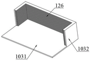
Fig. 8 is a perspective view of a carriage according to an embodiment of the present application.
Fig. 9 is a perspective view of a transfer mechanism according to an embodiment of the present application.
Fig. 10 is a perspective view of a cutting mechanism according to an embodiment of the present application.
Description of reference numerals: 100-workbench, 200-transfer mechanism, 300-cutting mechanism, 101-support frame, 102-lifting plate, 103-bearing frame, 1031-bottom plate, 1032-U-shaped frame, 104-recess, 105-limit rod, 106-first chute, 107-second chute, 108-fixture block, 109-sliding rod, 110-support plate, 111-first spring, 112-baffle, 113-support, 114-top rod, 115-clamp plate, 116-clamp groove, 117-second spring, 118-retainer ring, 119-limit groove, 120-limit block, 121-convex plate, 122-push rod, 123-first moving block, 124-support bar, 125-retainer bar, 126-partition plate, 201-connecting rod, 202-suction cup, 203-first telescopic rod, 204-slider, 205-through groove, 301-moving frame, 302-rotating shaft, 303-limit frame, 304-track, 305-laser cutting head, 306-second telescopic rod, 307-second moving block, 308-motor 317, 309-connecting block, 309-312, support rod, 312-312, 311-third telescopic rod, 311-mounting plate, 316-side plate, pin, 316-third telescopic rod, and side plate.
Detailed Description
To make the objects, technical solutions and advantages of the embodiments of the present invention clearer, the following detailed description of the embodiments of the present invention is made with reference to the accompanying drawings, but the embodiments described in the present invention are some, not all, of the embodiments of the present invention.
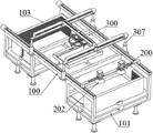
As shown in fig. 1 to 10, an embodiment of the present application provides an automatic cutting device for a printed circuit board, including: a workbench 100, a transfer mechanism 200 and a cutting mechanism 300.
As shown in fig. 1 to 3, two sides of a workbench 100 in a length direction are provided with support frames 101, the support frames 101 are provided with lifting plates 102 moving in a vertical direction, the lifting plates 102 are provided with bearing frames 103 for placing a circuit board, a concave portion 104 is provided on a surface of the workbench 100, four synchronously moving limiting rods 105 are provided in the concave portion 104, and a rectangular area is defined between the limiting rods 105; the transfer mechanism 200 is arranged above the workbench 100 and comprises a connecting rod 201 moving between the two support frames 101, and two symmetrically arranged suckers 202 moving in opposite directions are arranged on the connecting rod 201 and used for sucking the circuit board in the bearing frame 103 to a rectangular area surrounded by the limiting rods 105; the cutting mechanism 300 is arranged above the workbench 100 and comprises a laser cutting head 305 and a movable frame 301 which moves along the length and width direction of the workbench 100, a detachable limiting frame 303 is arranged on the movable frame 301, a track 304 with a track matched with the shape to be cut of the circuit board is arranged on the inner wall of the limiting frame 303, and the upper end of the laser cutting head 305 is matched with the track 304 and moves along the track.
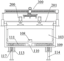
Specifically, as shown in fig. 1 to 3 and 6, a first sliding groove 106 is disposed on one side of the lifting plate 102 in the length direction, a baffle 112 is further disposed on the other side of the lifting plate 102 in the length direction, the length direction of the first sliding groove 106 is parallel to the width direction of the lifting plate 102, second sliding grooves 107 perpendicular to the first sliding groove 106 are further disposed on two sides of the first sliding groove 106, the two second sliding grooves 107 are symmetrically disposed, a clamping block 108 is disposed in each of the first sliding groove 106 and the second sliding groove 107, the lower end of the clamping block 108 is sleeved on the sliding rod 109, two ends of the sliding rod 109 are mounted on the supporting plate 110, the supporting plate 110 is mounted on the bottom surface of the lifting plate 102, the sliding rod 109 is further sleeved with a first spring 111, two ends of the first spring 111 are respectively connected to the supporting plate 110 and the clamping block 108 near the center of the lifting plate 102, and the first spring 111 is always in a stretching state, so that the clamping blocks 108 in the second sliding grooves 107 have a tendency of moving towards each other, and the clamping block of the first sliding groove 106 has a tendency towards the baffle 112; when the bearing frame 103 is used, the bearing frame 103 is located in the area between the baffle 112 and the fixture block 108, and the fixture block 108 clamps the bearing frame 103 under the elastic force of the first spring 111.
More specifically, the upper half part of the inner side of the clamping block 108 is an inclined surface, the inclined surface is located above the blocking strip 125, and the lower half part is still a vertical surface, so that when the bearing frame 103 is placed on the lifting plate 102, the inclined surface can be in contact with the edge of the bearing frame 103, and the bearing frame 103 can be more easily placed on the lifting plate 102.
Specifically, as shown in fig. 1 to 3 and 6, a plurality of brackets 113 are disposed on the bottom surface of the support frame 101, a push rod 114 penetrates through the brackets 113, the upper end of the push rod 114 passes through the support frame 101 and is provided with a clamping plate 115, a plurality of clamping grooves 116 are disposed on the bottom surface of the lifting plate 102, the clamping plate 115 is fitted in the clamping grooves 116, the lifting plate 102 can be kept stable in the process of ascending and descending, a second spring 117 is further sleeved on the push rod 114, two ends of the second spring 117 are respectively abutted to the clamping plate 115 and the brackets 113, the second spring 117 is always in a compressed state, under the elastic force of the second spring 117, the lifting plate 102 is forced to move upwards, in the process of continuously taking out the circuit board from the bearing frame 103, the lifting plate 102 also slowly ascends, so that the circuit board is conveniently transferred by the transfer mechanism 200, and a retaining ring 118 is further disposed at the lower end of the push rod 114 and is abutted to the brackets 113 to prevent the push rod 114 from falling out of the brackets 113.
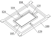
Specifically, as shown in fig. 4 to 5, four limiting grooves 119 are formed in the concave portion 104 and evenly arranged at intervals in the circumferential direction, a limiting block 120 is arranged on the bottom surface of the limiting rod 105, the limiting block 120 is fitted in the limiting groove 119, a push rod 122 is hinged to the lower end of the limiting block 120, one end of the push rod 122 is hinged to a first moving block 123, the first moving block 123 is connected to the moving end of the vertical lifting mechanism, the vertical lifting mechanism is installed on the bottom surface of the workbench 100, when the first moving block 123 is driven to move up and down, the push rod 122 can push the limiting rod 105 to move along the limiting grooves 119, so that the distance between the two limiting rods 105 is adjusted, and the two sides of the limiting block 120 are further provided with convex plates 121, the convex plates 121 contact with the bottom surface of the workbench 100, and when the limiting rod 105 is prevented from moving, the limiting block 120 is separated from the limiting grooves 119.
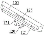
Specifically, as shown in fig. 4 to 5 and 7, the inner side of the limiting rod 105 is provided with a support bar 124 along the length direction thereof for supporting a circuit board, and both ends of the limiting rod 105 are inclined planes, when the limiting rod 105 encloses a minimum rectangular area, the end portions of two adjacent limiting rods 105 are connected end to end, and the inclined planes are matched with each other, the inner side of the limiting rod 105 is further provided with a barrier bar 125, the barrier bar 125 is located above the support bar 124 and has a width smaller than that of the support bar 124, when the two parallel limiting rods 105 move in opposite directions, the inner side of the limiting rod 105 has a certain squeezing effect on the side edge of the circuit board, so as to clamp the circuit board, and the barrier bar 125 can limit the upper and lower directions of the circuit board, so as to avoid extruding the circuit board from the rectangular area in the limiting process, and the inner side of the limiting rod 105 is inclined plane, so that the circuit board can more easily enter the rectangular area enclosed by the limiting rod 105.
Specifically, as shown in fig. 9, the suction cups 202 are mounted at the moving end of the first telescopic rod 203, the first telescopic rod 203 is mounted on the sliding block 204, the sliding block 204 is slidably mounted on the connecting rod 201, after the sliding block 204 moves to a predetermined position, the sliding block 204 can be locked with respect to the connecting rod 201 by using screws, so that the position between the two suction cups 202 can be adjusted to adapt to circuit boards with different sizes, two symmetrically arranged through grooves 205 are arranged on the connecting rod 201 along the length direction thereof for penetrating through the first telescopic rod 203, two ends of the connecting rod 201 are respectively mounted at the moving end of the first linear mechanism, and the first linear mechanism is mounted on the workbench 100 and is arranged along the width direction thereof.
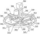
Specifically, as shown in fig. 1 and 10, two rotating shafts 302 are arranged on a moving frame 301, the two rotating shafts 302 are connected through a belt, one end of one rotating shaft 302 is connected with a motor 308, the motor 308 is installed on the moving frame 301, the lower end of the other rotating shaft 302 penetrates through the moving frame 301 and is detachably installed with a connecting block 309, for example, a screw thread or a snap connection, a plurality of supporting rods 310 are arranged on the periphery of the connecting block 309, a laser cutting head 305 is installed on a supporting block 312 so that the laser cutting head 305 can rotate around the axis of the rotating shaft 302, the supporting block 312 is sleeved on the supporting rods 310, a third spring 313 is further sleeved on the supporting rods 310, two ends of the third spring 313 are respectively abutted to the connecting blocks 309 and 312, the supporting block 312 can move along the axis of the supporting block 310, the supporting block 312 always has a tendency to move in a direction away from the connecting block 309 under the urging of the third spring 313, one end of the supporting rod 310 is further provided with a stopper 311 for contacting with the supporting block 312, and the connecting block 309 and the rotating shaft 302 can be detachably connected, so that the whole can be replaced and maintained according to the size of the circuit board unit.
Specifically, as shown in fig. 10, a protruding rod 314 is disposed on the supporting block 312, two rollers 315 rotating around the axis of the protruding rod 314 are disposed on the protruding rod 314, the track 304 is located between the two rollers 315, and the side surface of the roller 315 contacts with the inner wall of the position-limiting frame 303, when the rotating shaft 302 rotates, the supporting rod 310 rotates around the axis of the rotating shaft 302, so that the roller 315 moves along the track of the position-limiting frame 303, and under the action of a third spring 313, the roller 315 always keeps contact with the position-limiting frame 303, so that the cutting track of the laser cutting head 305 is the same as that of the circuit board.
Specifically, as shown in fig. 10, the surface of the limiting frame 303 is provided with a plurality of vertical plates 316, mounting plates 317 penetrate through the vertical plates 316, one ends of the mounting plates 317 penetrate through the movable frame 301, bolts 318 penetrate through the movable frame 301 and are used for positioning the mounting plates 317, and side plates 319 are arranged at the other ends of the mounting plates 317 and are used for contacting with the outer walls of the vertical plates 316, so that the limiting frame 303 is detachably mounted on the movable frame 301, and different limiting frames 303 can be conveniently selected according to the shapes of the circuit board units.
Specifically, as shown in fig. 1 and 10, the moving frame 301 is mounted on the second moving block 306, the second moving block 306 is connected to the moving end of the second linear mechanism, the second linear mechanism is mounted on the third linear mechanism, the third linear mechanism is mounted on the moving end of the second telescopic rod 307, and the second telescopic rod 307 is mounted on the workbench 100.
Specifically, as shown in fig. 1 and 8, in order to facilitate the transfer mechanism 200 to transfer the circuit board, the carrying frame 103 is composed of a bottom plate 1031 and a U-shaped frame 1032, an opening of the U-shaped frame 1032 faces the workbench 100, and a plurality of partition plates 126 are disposed on an inner side of the U-shaped frame 1032, and the partition plates 126 are U-shaped and used for receiving the circuit board.
Specifically, the first linear mechanism, the second linear mechanism, the third linear mechanism and the vertical lifting mechanism can be driven by adopting a motor screw rod mode, and can also be driven by adopting a hydraulic or pneumatic telescopic rod.
The printed circuit board cutting method applies the automatic printed circuit board cutting device and comprises the following steps:
s01, placing a bearing frame 103 bearing a circuit board on one of the support frames 101;
s02, transferring the circuit board in the bearing frame 103 to a rectangular area surrounded by the limiting rods 105 by the transfer mechanism 200;
s03, cutting the circuit board by the cutting mechanism 300 according to the shape to be cut;
and S04, transferring the cut circuit board to another bearing frame 103 by the transfer mechanism 200.
The detailed operation steps for cutting the circuit board by utilizing the automatic cutting device of the printed circuit board are as follows:
firstly, placing the bearing frame 103 bearing the circuit board on the lifting plate 102 of one of the support frames 101, placing the empty bearing frame 103 on the lifting plate 102 of the other support frame 101, clamping the periphery of the bearing frame 103 by using the clamping block 108, wherein the bottom plate 1031 can also abut against the baffle plate 112, so that the bearing frame 103 is stably placed, the openings of the two bearing frames 103 face the workbench 100, and under the action of the second spring 117, the lifting plate 102 has a tendency of moving upwards; the distance between the two parallel limiting rods 105 is adjusted according to the size of the circuit board to be cut, the vertical lifting mechanism is started, the first moving block 123 is driven to move in the vertical direction, and the limiting blocks 120 below the limiting rods 105 are hinged with the first moving block 123 through the push rods 122, so that the limiting rods 105 are forced to synchronously move relatively.
Then, the limiting frame 303 with a suitable shape is selected according to the circuit board unit to be cut, for example, the circular circuit board unit is selected, the rectangular circuit board unit is selected to be the rectangular limiting frame 303, the limiting frame 303 obliquely passes through the supporting rod 310 and is placed above the supporting rod 310, then the supporting block 312 is pushed towards the connecting block 309, the third spring 313 is compressed, then the rail 304 on the inner side of the limiting frame 303 is clamped between the two rollers 315, the rollers 315 are in contact with the inner wall of the limiting frame 303, then the mounting plate 317 sequentially passes through the limiting frame 303 and the moving frame 301, and the mounting plate 317 is locked by the bolts 318.
At this moment, the circuit board can be cut, the first linear mechanism is started first, the connecting rod 201 is driven to move towards the bearing frame 103 with the circuit board placed, then the first telescopic rod 203 is started, the sucking disc 202 descends until the circuit board is adsorbed, then the first linear mechanism is started again, the connecting rod 201 is driven to move to the center of the concave part 104, then the first telescopic rod 203 is started, the sucking disc 202 continues to descend until the circuit board enters a rectangular area surrounded by the four limiting rods 105, the circuit board is abutted to the supporting bar 124, then the vertical lifting mechanism is started again, two parallel limiting rods 105 move in opposite directions until the side edges of the circuit board are abutted to the inner side edges of the limiting rods 105, the blocking bar 125 on the inner side of the circuit board is limited in the vertical direction, then the sucking disc 202 does not adsorb the circuit board any more, the sucking disc 202 is retracted, and the sucking disc 202 is transferred to the area outside the workbench 100.
Then, the second linear mechanism and the third linear mechanism are started, the second moving block 306 is moved to a position above a circuit board unit to be cut, the second telescopic rod 307 is started, the second moving block 306 is driven to descend until the laser cutting head 305 moves to a position where the circuit board unit can be cut, the motor 308 is started to drive the rotating shaft 302 to rotate, so that the supporting rod 310 is driven to rotate around the axis of the rotating shaft, the supporting block 312 is forced to move along the track of the limiting frame 303 due to the fact that the roller 315 is matched with the inner wall of the limiting frame 303, namely the laser cutting head 305 moves along the track, so that the circuit board unit is quickly cut, after all circuit board units of the whole circuit board are cut completely, the cutting mechanism 300 is lifted, the vertical lifting mechanism is started again, the limiting rod 105 moves towards the opposite direction for the same distance as before, and finally, the circuit board after being cut is transferred to another bearing frame 103 through the transfer mechanism 200.
The above is only a preferred embodiment of the present invention and is not intended to limit the present invention, and it is apparent that those skilled in the art can make various changes and modifications to the present invention without departing from the spirit and scope of the present invention. Thus, if such modifications and variations of the present invention fall within the scope of the claims of the present invention and their equivalents, the present invention is also intended to include such modifications and variations.
Claims (10)
1. An automatic cutting device for a printed circuit board, comprising:
the circuit board positioning device comprises a workbench (100), wherein supporting frames (101) are arranged on two sides of the workbench in the length direction, a lifting plate (102) moving in the vertical direction is arranged on each supporting frame (101), a bearing frame (103) used for placing a circuit board is arranged on each lifting plate (102), a concave part (104) is arranged on the surface of the workbench (100), four limiting rods (105) moving synchronously are arranged in each concave part (104), and a rectangular area is defined between every two limiting rods (105);
the transfer mechanism (200) is arranged above the workbench (100) and comprises a connecting rod (201) moving between the two support frames (101), and two symmetrically-arranged suckers (202) moving in opposite directions are arranged on the connecting rod (201) and used for adsorbing a circuit board in the bearing frame (103) to a rectangular area surrounded by the limiting rods (105);
the cutting mechanism (300) is arranged above the workbench (100) and comprises a laser cutting head (305) and a moving frame (301) moving along the length and width directions of the workbench (100), a detachable limiting frame (303) is installed on the moving frame (301), a track (304) with a track matched with the shape to be cut of the circuit board is arranged on the inner wall of the limiting frame (303), and the upper end of the laser cutting head (305) is matched with the track (304) and moves along the track.
2. The automatic cutting device for the printed circuit board according to claim 1, wherein a first sliding groove (106) is formed in one side of the lifting plate (102) in the length direction, the length direction of the first sliding groove (106) is parallel to the width direction of the lifting plate (102), a second sliding groove (107) perpendicular to the first sliding groove is further formed in each of two sides of the first sliding groove (106), a clamping block (108) is arranged in each of the first sliding groove (106) and the second sliding groove (107), the lower end of each clamping block (108) is sleeved on a sliding rod (109), two ends of each sliding rod (109) are mounted on a support plate (110), each support plate (110) is mounted on the bottom surface of the lifting plate (102), each sliding rod (109) is further sleeved with a first spring (111), two ends of each first spring (111) are respectively connected with the support plate (110) and the clamping block (108) close to the center of the lifting plate (102), and each first spring (111) is in a stretching state all the time;
the other side of the lifting plate (102) in the length direction is further provided with a baffle plate (112), and when the lifting plate is used, the bearing frame (103) is located in an area between the baffle plate (112) and the clamping block (108).
3. The automatic printed circuit board cutting device according to claim 1, wherein a plurality of brackets (113) are arranged on the bottom surface of the support frame (101), a top rod (114) penetrates through the brackets (113), the upper end of the top rod (114) penetrates through the support frame (101) and is provided with a clamping plate (115), a plurality of clamping grooves (116) are arranged on the bottom surface of the lifting plate (102), the clamping plate (115) is fitted in the clamping grooves (116), a second spring (117) is further sleeved on the top rod (114), two ends of the second spring (117) are respectively abutted to the clamping plate (115) and the brackets (113), and a retainer ring (118) is further arranged at the lower end of the top rod (114) and is abutted to the brackets (113).
4. The automatic cutting device for the printed circuit board according to claim 1, wherein four limiting grooves (119) are formed in the concave portion (104) and are evenly arranged at intervals in the circumferential direction, a limiting block (120) is arranged on the bottom surface of the limiting rod (105), the limiting block (120) is fitted in the limiting groove (119), protruding plates (121) are further arranged on two sides of the limiting block (120), the protruding plates (121) are in contact with the bottom surface of the worktable (100), a push rod (122) is hinged to the lower end of the limiting block (120), one end of the push rod (122) is hinged to a first moving block (123), the first moving block (123) is connected to a moving end of a vertical lifting mechanism, and the vertical lifting mechanism is mounted on the bottom surface of the worktable (100).
5. The automatic cutting device for the printed circuit board according to claim 1, wherein a support bar (124) is arranged on the inner side of the limiting rod (105) along the length direction of the limiting rod for carrying the circuit board, both ends of the limiting rod (105) are inclined planes, when the limiting rod (105) encloses a minimum rectangular area, the ends of two adjacent limiting rods (105) are connected end to end, and the inclined planes are matched with each other, a blocking bar (125) is further arranged on the inner side of the limiting rod (105), the blocking bar (125) is arranged above the support bar (124), and the width of the blocking bar is smaller than the width of the support bar (124), an inclined plane is arranged on the inner side of the limiting rod (105), and the inclined plane is arranged above the blocking bar (125).
6. The automatic cutting device for the printed circuit board according to claim 1, wherein the suction cup (202) is mounted at a moving end of a first telescopic rod (203), the first telescopic rod (203) is mounted on a sliding block (204), the sliding block (204) is slidably mounted on the connecting rod (201) and locked by a screw, two symmetrically arranged through grooves (205) are formed in the connecting rod (201) along the length direction of the connecting rod for penetrating through the first telescopic rod (203), two ends of the connecting rod (201) are respectively mounted at a moving end of a first linear mechanism, and the first linear mechanism is mounted on the worktable (100) and arranged along the width direction of the worktable.
7. The automatic cutting device for the printed circuit board according to claim 1, wherein two rotating shafts (302) are arranged on the moving frame (301), the two rotating shafts (302) are connected through a belt, one end of one rotating shaft (302) is connected with a motor (308), the motor (308) is installed on the moving frame (301), the lower end of the other rotating shaft (302) penetrates through the moving frame (301) and is detachably provided with a connecting block (309), a plurality of supporting rods (310) are arranged on the periphery of the connecting block (309), the laser cutting head (305) is installed on a supporting block (312), the supporting block (312) is sleeved on the supporting rods (310), a third spring (313) is further sleeved on the supporting rod (310), two ends of the third spring (313) are respectively abutted to the connecting block (309) and the supporting block (312), and a stop block (311) is further arranged at one end of the supporting rod (310) and is used for contacting with the supporting block (312).
8. The automatic cutting device for the printed circuit board according to claim 7, wherein a protruding rod (314) is arranged on the supporting block (312), two rollers (315) rotating around the axis of the protruding rod (314) are arranged on the protruding rod (314), the track (304) is located between the two rollers (315), and the side surface of the roller (315) is in contact with the inner wall of the limiting frame (303).
9. The automatic cutting device for the printed circuit board according to claim 1, wherein a plurality of vertical plates (316) are arranged on the surface of the limiting frame (303), mounting plates (317) are arranged on the vertical plates (316) in a penetrating manner, one ends of the mounting plates (317) are arranged on the movable frame (301), bolts (318) are arranged on the movable frame (301) in a penetrating manner and used for positioning the mounting plates (317), and side plates (319) are arranged at the other ends of the mounting plates (317) and used for being in contact with the outer walls of the vertical plates (316).
10. A printed circuit board cutting method using the automatic printed circuit board cutting device of any one of claims 1~9, comprising:
s01, placing a bearing frame (103) bearing a circuit board on one of the support frames (101);
s02, transferring the circuit board in the bearing frame (103) to a rectangular area surrounded by the limiting rods (105) by the transfer mechanism (200);
s03, cutting the circuit board by the cutting mechanism (300) according to the shape to be cut;
s04, the transfer mechanism (200) transfers the cut circuit board to another bearing frame (103).
Priority Applications (1)
| Application Number | Priority Date | Filing Date | Title |
|---|---|---|---|
| CN202211593047.4A CN115592280B (en) | 2022-12-13 | 2022-12-13 | Automatic cutting device and method for printed circuit board |
Applications Claiming Priority (1)
| Application Number | Priority Date | Filing Date | Title |
|---|---|---|---|
| CN202211593047.4A CN115592280B (en) | 2022-12-13 | 2022-12-13 | Automatic cutting device and method for printed circuit board |
Publications (2)
| Publication Number | Publication Date |
|---|---|
| CN115592280A true CN115592280A (en) | 2023-01-13 |
| CN115592280B CN115592280B (en) | 2023-03-10 |
Family
ID=84853964
Family Applications (1)
| Application Number | Title | Priority Date | Filing Date |
|---|---|---|---|
| CN202211593047.4A Active CN115592280B (en) | 2022-12-13 | 2022-12-13 | Automatic cutting device and method for printed circuit board |
Country Status (1)
| Country | Link |
|---|---|
| CN (1) | CN115592280B (en) |
Cited By (7)
| Publication number | Priority date | Publication date | Assignee | Title |
|---|---|---|---|---|
| CN116072581A (en) * | 2023-04-03 | 2023-05-05 | 四川旭茂微科技有限公司 | Chip die bonding device |
| CN116511791A (en) * | 2023-03-13 | 2023-08-01 | 四川中天瑞能空调设备有限公司 | Axial flow fan shell welding device |
| CN116618860A (en) * | 2023-07-26 | 2023-08-22 | 成都莒纳新材料科技有限公司 | Cutting device for manufacturing electrode plate |
| CN117103367A (en) * | 2023-10-24 | 2023-11-24 | 美尚精密制造(南通)有限公司 | Cutting equipment for production and processing on circuit board |
| CN117139970A (en) * | 2023-10-31 | 2023-12-01 | 天津世亚模具股份有限公司 | Stamping workpiece welding jig |
| CN117832135A (en) * | 2024-03-04 | 2024-04-05 | 四川晶辉半导体有限公司 | Semiconductor lead frame glues core equipment |
| CN117832135B (en) * | 2024-03-04 | 2024-05-10 | 四川晶辉半导体有限公司 | Semiconductor lead frame glues core equipment |
Citations (19)
| Publication number | Priority date | Publication date | Assignee | Title |
|---|---|---|---|---|
| EP0449462A2 (en) * | 1990-03-15 | 1991-10-02 | Canon Kabushiki Kaisha | Roll stamper for moulding substrate sheet for information recording mediums, procedure for preparation of the same, and procedure for producing substrate sheets for information recording mediums |
| US6437286B1 (en) * | 1999-04-30 | 2002-08-20 | W. A. Whitney Co. | Slag collection and removal system for a heavy duty laser-equipped machine tool |
| US20050106926A1 (en) * | 2003-11-17 | 2005-05-19 | Liken Peter A. | Independently-adjustable circuit board carrier |
| US20110098969A1 (en) * | 2009-03-13 | 2011-04-28 | Knudsen N Eric | Post sleeve positioning apparatus and method |
| CN111673298A (en) * | 2020-07-28 | 2020-09-18 | 赵之銮 | Circuit board production cutting device of steerable length |
| CN112317973A (en) * | 2020-10-13 | 2021-02-05 | 苏州市博通照明电器有限公司 | Cutting device is used in photographic lamp plate processing |
| CN112372302A (en) * | 2020-11-02 | 2021-02-19 | 张群 | Collude indisputable equipment of welding and milling flat welding seam device |
| CN112996255A (en) * | 2021-04-21 | 2021-06-18 | 四川超声印制板有限公司 | Printed circuit board edge copper foil cutting device |
| CN112996234A (en) * | 2021-04-23 | 2021-06-18 | 四川超声印制板有限公司 | Circuit board and circuit board copper foil pasting device |
| CN214134623U (en) * | 2020-10-22 | 2021-09-07 | 中材(天津)重型机械有限公司 | Manipulator for welding hopper |
| CN113369696A (en) * | 2021-06-25 | 2021-09-10 | 江苏一言机械科技有限公司 | Optical fiber laser and Tig combined welding machine |
| CN113751864A (en) * | 2021-09-18 | 2021-12-07 | 深圳市华丰泽电子有限公司 | Titanium alloy plate laser cutting device for aerospace |
| CN215545913U (en) * | 2021-09-22 | 2022-01-18 | 上海乐昌汽车配件有限公司 | Feeding and discharging mechanism for cutting machine |
| CN114029632A (en) * | 2021-12-03 | 2022-02-11 | 北京华鸿方舟科技有限公司 | Three-dimensional five-axis laser cutting method and laser cutting system thereof |
| CN114227809A (en) * | 2022-02-25 | 2022-03-25 | 四川英创力电子科技股份有限公司 | Presser foot replacing device for drilling of circuit board |
| CN114538065A (en) * | 2022-04-25 | 2022-05-27 | 四川英创力电子科技股份有限公司 | Soak circuit board transfer device |
| CN114654080A (en) * | 2022-03-04 | 2022-06-24 | 衢州学院 | Flowing water type automobile metal plate annular laser cutting device |
| CN114786354A (en) * | 2022-04-15 | 2022-07-22 | 刘菲菲 | PCB board low temperature rubberizing equipment |
| CN217756176U (en) * | 2022-08-12 | 2022-11-08 | 四川龙华光电薄膜股份有限公司 | Automatic film cutting equipment |
-
2022
- 2022-12-13 CN CN202211593047.4A patent/CN115592280B/en active Active
Patent Citations (19)
| Publication number | Priority date | Publication date | Assignee | Title |
|---|---|---|---|---|
| EP0449462A2 (en) * | 1990-03-15 | 1991-10-02 | Canon Kabushiki Kaisha | Roll stamper for moulding substrate sheet for information recording mediums, procedure for preparation of the same, and procedure for producing substrate sheets for information recording mediums |
| US6437286B1 (en) * | 1999-04-30 | 2002-08-20 | W. A. Whitney Co. | Slag collection and removal system for a heavy duty laser-equipped machine tool |
| US20050106926A1 (en) * | 2003-11-17 | 2005-05-19 | Liken Peter A. | Independently-adjustable circuit board carrier |
| US20110098969A1 (en) * | 2009-03-13 | 2011-04-28 | Knudsen N Eric | Post sleeve positioning apparatus and method |
| CN111673298A (en) * | 2020-07-28 | 2020-09-18 | 赵之銮 | Circuit board production cutting device of steerable length |
| CN112317973A (en) * | 2020-10-13 | 2021-02-05 | 苏州市博通照明电器有限公司 | Cutting device is used in photographic lamp plate processing |
| CN214134623U (en) * | 2020-10-22 | 2021-09-07 | 中材(天津)重型机械有限公司 | Manipulator for welding hopper |
| CN112372302A (en) * | 2020-11-02 | 2021-02-19 | 张群 | Collude indisputable equipment of welding and milling flat welding seam device |
| CN112996255A (en) * | 2021-04-21 | 2021-06-18 | 四川超声印制板有限公司 | Printed circuit board edge copper foil cutting device |
| CN112996234A (en) * | 2021-04-23 | 2021-06-18 | 四川超声印制板有限公司 | Circuit board and circuit board copper foil pasting device |
| CN113369696A (en) * | 2021-06-25 | 2021-09-10 | 江苏一言机械科技有限公司 | Optical fiber laser and Tig combined welding machine |
| CN113751864A (en) * | 2021-09-18 | 2021-12-07 | 深圳市华丰泽电子有限公司 | Titanium alloy plate laser cutting device for aerospace |
| CN215545913U (en) * | 2021-09-22 | 2022-01-18 | 上海乐昌汽车配件有限公司 | Feeding and discharging mechanism for cutting machine |
| CN114029632A (en) * | 2021-12-03 | 2022-02-11 | 北京华鸿方舟科技有限公司 | Three-dimensional five-axis laser cutting method and laser cutting system thereof |
| CN114227809A (en) * | 2022-02-25 | 2022-03-25 | 四川英创力电子科技股份有限公司 | Presser foot replacing device for drilling of circuit board |
| CN114654080A (en) * | 2022-03-04 | 2022-06-24 | 衢州学院 | Flowing water type automobile metal plate annular laser cutting device |
| CN114786354A (en) * | 2022-04-15 | 2022-07-22 | 刘菲菲 | PCB board low temperature rubberizing equipment |
| CN114538065A (en) * | 2022-04-25 | 2022-05-27 | 四川英创力电子科技股份有限公司 | Soak circuit board transfer device |
| CN217756176U (en) * | 2022-08-12 | 2022-11-08 | 四川龙华光电薄膜股份有限公司 | Automatic film cutting equipment |
Non-Patent Citations (2)
| Title |
|---|
| 张军伟;申祖武;田会方;周承光;: "基于PLC的碳纤维预浸布超声波切割装置的系统设计" * |
| 龙云;: "浅析PCB板先进切割技术及切割精度控制" * |
Cited By (11)
| Publication number | Priority date | Publication date | Assignee | Title |
|---|---|---|---|---|
| CN116511791A (en) * | 2023-03-13 | 2023-08-01 | 四川中天瑞能空调设备有限公司 | Axial flow fan shell welding device |
| CN116511791B (en) * | 2023-03-13 | 2023-09-01 | 四川中天瑞能空调设备有限公司 | Axial flow fan shell welding device |
| CN116072581A (en) * | 2023-04-03 | 2023-05-05 | 四川旭茂微科技有限公司 | Chip die bonding device |
| CN116072581B (en) * | 2023-04-03 | 2023-05-30 | 四川旭茂微科技有限公司 | Chip die bonding device |
| CN116618860A (en) * | 2023-07-26 | 2023-08-22 | 成都莒纳新材料科技有限公司 | Cutting device for manufacturing electrode plate |
| CN116618860B (en) * | 2023-07-26 | 2023-11-24 | 成都莒纳新材料科技有限公司 | Cutting device for manufacturing electrode plate |
| CN117103367A (en) * | 2023-10-24 | 2023-11-24 | 美尚精密制造(南通)有限公司 | Cutting equipment for production and processing on circuit board |
| CN117103367B (en) * | 2023-10-24 | 2024-01-26 | 美尚精密制造(南通)有限公司 | Cutting equipment for production and processing on circuit board |
| CN117139970A (en) * | 2023-10-31 | 2023-12-01 | 天津世亚模具股份有限公司 | Stamping workpiece welding jig |
| CN117832135A (en) * | 2024-03-04 | 2024-04-05 | 四川晶辉半导体有限公司 | Semiconductor lead frame glues core equipment |
| CN117832135B (en) * | 2024-03-04 | 2024-05-10 | 四川晶辉半导体有限公司 | Semiconductor lead frame glues core equipment |
Also Published As
| Publication number | Publication date |
|---|---|
| CN115592280B (en) | 2023-03-10 |
Similar Documents
| Publication | Publication Date | Title |
|---|---|---|
| CN115592280B (en) | Automatic cutting device and method for printed circuit board | |
| CN109623372B (en) | Brake block assembly equipment | |
| CA2023160C (en) | Apparatus for stripping molded rubber products from a product sheet | |
| US4565443A (en) | Printing apparatus | |
| CN116214160A (en) | Full-automatic assembly system and assembly method | |
| CN116544163B (en) | Lead frame conveying device | |
| CN112171265B (en) | Sliding switch sliding cover assembly equipment and sliding switch assembly system | |
| CN106629063B (en) | Automatic chip feeding and powder cleaning device and working method thereof | |
| CN209954139U (en) | Automatic assembling equipment | |
| CN116119295A (en) | Slicing machine for packaging thermal printing sheets | |
| CN217369298U (en) | Feeding mechanism of laser chip testing and sorting machine | |
| GB2296914A (en) | Removing articles from a stack | |
| CN115547915A (en) | Wafer exposure clamp and exposure device | |
| CN212727601U (en) | Chip mounter clamping device | |
| CN113601137A (en) | Compressor blade assembling device and method and assembling equipment | |
| CN211614087U (en) | Middle-layer stamping production line of electric cooker | |
| CN112548356A (en) | Automatic laser marking device | |
| CN113386197A (en) | Circuit board cutting device and method | |
| CN112192630A (en) | Rubber sealing strip cutting and feeding device and method | |
| CN218019774U (en) | Spoon transfer device | |
| CN112551128B (en) | Automatic feeding and discharging equipment for PCB testing | |
| JP2848781B2 (en) | Curved glass plate positioning device | |
| CN217800677U (en) | High-efficient automatic burnishing machine device | |
| CN116715005B (en) | SFP optical module washs and uses conveyor | |
| CN213733966U (en) | A material collecting device for temperature sensing CTP platemaking machine |
Legal Events
| Date | Code | Title | Description |
|---|---|---|---|
| PB01 | Publication | ||
| PB01 | Publication | ||
| SE01 | Entry into force of request for substantive examination | ||
| SE01 | Entry into force of request for substantive examination | ||
| GR01 | Patent grant | ||
| GR01 | Patent grant |