CN115540532A - Feed granulating and drying system and process - Google Patents
Feed granulating and drying system and process Download PDFInfo
- Publication number
- CN115540532A CN115540532A CN202211270015.0A CN202211270015A CN115540532A CN 115540532 A CN115540532 A CN 115540532A CN 202211270015 A CN202211270015 A CN 202211270015A CN 115540532 A CN115540532 A CN 115540532A
- Authority
- CN
- China
- Prior art keywords
- drying
- plate
- support
- assembly
- induction
- Prior art date
- Legal status (The legal status is an assumption and is not a legal conclusion. Google has not performed a legal analysis and makes no representation as to the accuracy of the status listed.)
- Pending
Links
Images


Classifications
-
- F—MECHANICAL ENGINEERING; LIGHTING; HEATING; WEAPONS; BLASTING
- F26—DRYING
- F26B—DRYING SOLID MATERIALS OR OBJECTS BY REMOVING LIQUID THEREFROM
- F26B11/00—Machines or apparatus for drying solid materials or objects with movement which is non-progressive
- F26B11/02—Machines or apparatus for drying solid materials or objects with movement which is non-progressive in moving drums or other mainly-closed receptacles
- F26B11/04—Machines or apparatus for drying solid materials or objects with movement which is non-progressive in moving drums or other mainly-closed receptacles rotating about a horizontal or slightly-inclined axis
- F26B11/0463—Machines or apparatus for drying solid materials or objects with movement which is non-progressive in moving drums or other mainly-closed receptacles rotating about a horizontal or slightly-inclined axis having internal elements, e.g. which are being moved or rotated by means other than the rotating drum wall
- F26B11/0477—Machines or apparatus for drying solid materials or objects with movement which is non-progressive in moving drums or other mainly-closed receptacles rotating about a horizontal or slightly-inclined axis having internal elements, e.g. which are being moved or rotated by means other than the rotating drum wall for mixing, stirring or conveying the materials to be dried, e.g. mounted to the wall, rotating with the drum
- F26B11/0481—Machines or apparatus for drying solid materials or objects with movement which is non-progressive in moving drums or other mainly-closed receptacles rotating about a horizontal or slightly-inclined axis having internal elements, e.g. which are being moved or rotated by means other than the rotating drum wall for mixing, stirring or conveying the materials to be dried, e.g. mounted to the wall, rotating with the drum the elements having a screw- or auger-like shape, or form screw- or auger-like channels
-
- B—PERFORMING OPERATIONS; TRANSPORTING
- B01—PHYSICAL OR CHEMICAL PROCESSES OR APPARATUS IN GENERAL
- B01J—CHEMICAL OR PHYSICAL PROCESSES, e.g. CATALYSIS OR COLLOID CHEMISTRY; THEIR RELEVANT APPARATUS
- B01J2/00—Processes or devices for granulating materials, e.g. fertilisers in general; Rendering particulate materials free flowing in general, e.g. making them hydrophobic
- B01J2/20—Processes or devices for granulating materials, e.g. fertilisers in general; Rendering particulate materials free flowing in general, e.g. making them hydrophobic by expressing the material, e.g. through sieves and fragmenting the extruded length
-
- F—MECHANICAL ENGINEERING; LIGHTING; HEATING; WEAPONS; BLASTING
- F26—DRYING
- F26B—DRYING SOLID MATERIALS OR OBJECTS BY REMOVING LIQUID THEREFROM
- F26B21/00—Arrangements or duct systems, e.g. in combination with pallet boxes, for supplying and controlling air or gases for drying solid materials or objects
- F26B21/001—Drying-air generating units, e.g. movable, independent of drying enclosure
-
- F—MECHANICAL ENGINEERING; LIGHTING; HEATING; WEAPONS; BLASTING
- F26—DRYING
- F26B—DRYING SOLID MATERIALS OR OBJECTS BY REMOVING LIQUID THEREFROM
- F26B21/00—Arrangements or duct systems, e.g. in combination with pallet boxes, for supplying and controlling air or gases for drying solid materials or objects
- F26B21/004—Nozzle assemblies; Air knives; Air distributors; Blow boxes
-
- F—MECHANICAL ENGINEERING; LIGHTING; HEATING; WEAPONS; BLASTING
- F26—DRYING
- F26B—DRYING SOLID MATERIALS OR OBJECTS BY REMOVING LIQUID THEREFROM
- F26B25/00—Details of general application not covered by group F26B21/00 or F26B23/00
- F26B25/001—Handling, e.g. loading or unloading arrangements
- F26B25/002—Handling, e.g. loading or unloading arrangements for bulk goods
-
- F—MECHANICAL ENGINEERING; LIGHTING; HEATING; WEAPONS; BLASTING
- F26—DRYING
- F26B—DRYING SOLID MATERIALS OR OBJECTS BY REMOVING LIQUID THEREFROM
- F26B25/00—Details of general application not covered by group F26B21/00 or F26B23/00
- F26B25/04—Agitating, stirring, or scraping devices
-
- F—MECHANICAL ENGINEERING; LIGHTING; HEATING; WEAPONS; BLASTING
- F26—DRYING
- F26B—DRYING SOLID MATERIALS OR OBJECTS BY REMOVING LIQUID THEREFROM
- F26B25/00—Details of general application not covered by group F26B21/00 or F26B23/00
- F26B25/06—Chambers, containers, or receptacles
- F26B25/14—Chambers, containers, receptacles of simple construction
- F26B25/16—Chambers, containers, receptacles of simple construction mainly closed, e.g. drum
-
- F—MECHANICAL ENGINEERING; LIGHTING; HEATING; WEAPONS; BLASTING
- F26—DRYING
- F26B—DRYING SOLID MATERIALS OR OBJECTS BY REMOVING LIQUID THEREFROM
- F26B2200/00—Drying processes and machines for solid materials characterised by the specific requirements of the drying good
- F26B2200/08—Granular materials
-
- Y—GENERAL TAGGING OF NEW TECHNOLOGICAL DEVELOPMENTS; GENERAL TAGGING OF CROSS-SECTIONAL TECHNOLOGIES SPANNING OVER SEVERAL SECTIONS OF THE IPC; TECHNICAL SUBJECTS COVERED BY FORMER USPC CROSS-REFERENCE ART COLLECTIONS [XRACs] AND DIGESTS
- Y02—TECHNOLOGIES OR APPLICATIONS FOR MITIGATION OR ADAPTATION AGAINST CLIMATE CHANGE
- Y02P—CLIMATE CHANGE MITIGATION TECHNOLOGIES IN THE PRODUCTION OR PROCESSING OF GOODS
- Y02P60/00—Technologies relating to agriculture, livestock or agroalimentary industries
- Y02P60/80—Food processing, e.g. use of renewable energies or variable speed drives in handling, conveying or stacking
- Y02P60/87—Re-use of by-products of food processing for fodder production
Landscapes
- Engineering & Computer Science (AREA)
- Mechanical Engineering (AREA)
- General Engineering & Computer Science (AREA)
- Chemical & Material Sciences (AREA)
- Organic Chemistry (AREA)
- Chemical Kinetics & Catalysis (AREA)
- Drying Of Solid Materials (AREA)
Abstract
The invention relates to the field of feed processing, and particularly discloses a feed granulating and drying system and a process thereof, wherein the granulating and drying system comprises a granulating mechanism, a drying mechanism and a control system which are connected with the granulating mechanism, the drying mechanism comprises a bracket, a drying roller arranged on the bracket, a driving mechanism for controlling the rotation of the drying roller is arranged on the bracket, a hot air flow conducting assembly is arranged on the drying roller, a material guide sleeve is fixedly arranged on the bracket, the discharge end of the drying roller is rotationally connected with the material guide sleeve, a discharge port is arranged on the material guide sleeve, and a material guiding electromagnetic valve is arranged at the discharge port; the inner wall of the drying cavity is sequentially provided with a flow guide assembly from the feeding end to the discharging end, the material is guided into the induction supporting assembly, and the first material drying supporting assembly, the second material drying supporting assembly and the material are guided out of the induction supporting assembly. The fodder particulate matter can be detained for a long time in the region at each supporting component place, has improved effective stoving ageing.
Description
Technical Field
The invention relates to the field of feed processing, in particular to a feed granulating and drying system and a feed granulating and drying process.
Background
The term "feed" is a general term for food of all human-raised animals, and in a narrow sense, a general feed mainly refers to food of agricultural or animal-raised animals. During feed processing, soybean, bean pulp, corn, fish meal, amino acid, miscellaneous meal, whey powder, grease, meat and bone meal, grains, feed additives and other raw materials are mixed according to a certain proportion and then introduced into a granulator for granulation processing, and after the granulation processing is finished, the feed particles are transferred to a drying device for drying treatment.
Present drying equipment mainly includes drying drum, drive drying drum pivoted actuating mechanism and inlay the heating wire in drying drum, and drying drum's inner chamber is the toper, and drying drum is when progressively rotating, and its inside fodder particulate matter removes the discharge end from drying drum's feed end, and this kind of drying equipment is when carrying out drying process to the fodder particulate matter, and main existence is as follows drawback: 1. the applicant finds that when the length of the drying roller is 10m, the inclination of the inner cavity of the drying roller is 5 degrees, and the rotating speed of the drying roller is 3 circles/s, the time spent by moving the feed particles from the feeding end to the discharging end of the drying roller is about 5 minutes, and when the feed particles are accumulated at the discharging end of the drying roller, the feed particles are basically in a semi-dry state, under the condition, the length of the drying roller needs to be increased, so that the effective drying time of the feed particles in the drying roller is prolonged, and the drying equipment has the problems of large volume and high input cost;
2. after the heating wire is embedded in the conventional drying roller, moisture generated by evaporation in the drying roller is inconvenient to discharge in time, and the drying efficiency is greatly reduced;
3. when the existing drying roller dries feed particles, the temperature of an electric heating wire in the drying roller, the length of heating time and the drying time are set manually by virtue of operation experience, the working state of the drying roller cannot be intelligently controlled, and the problems that the feed particles are excessively dried and the drying is not in place often occur;
4. the existing drying and feeding methods include two methods, one is that after the granulation mechanism completes the granulation processing, manual work or feeding equipment quantitatively puts the feed particles into the drying drum, the drying drum starts to rotate, and the feed particles are dried, and the other method is that one or more granulation mechanisms are directly connected with the feeding port of the drying drum through the feeding equipment, and the granulation mechanisms directly perform continuous feeding to the drying drum, in this case, the feed particle supply amount can change according to the quantity change of the granulation mechanism, and meanwhile, when the granulation speed of the granulation mechanism changes, the drying drum needs to adaptively adjust the internal temperature and the drying time length, the existing drying equipment cannot adjust corresponding drying temperature and drying time length parameters according to the changed parameters, and the operation is completed by means of manual operation experience, and a large operation error exists.
Disclosure of Invention
The invention aims to solve the defects in the prior art and provides a feed granulating and drying system and a feed granulating and drying process.
First aspect, the utility model provides a pelletizing of fodder, drying system adopts following technical scheme:
a fodder granulating and drying system comprises a granulating mechanism, a drying mechanism and a control system, wherein the drying mechanism and the control system are connected with the granulating mechanism, the drying mechanism comprises a support and a drying roller arranged on the support, two ends of the drying roller are open, a drying cavity is arranged in the drying roller, the open end of one side of the drying roller is a feeding end, the open end of the other side of the drying roller is a discharging end, and the inner diameter of the drying cavity is gradually increased from the feeding end to the discharging end;
a driving mechanism for controlling the drying roller to rotate is arranged on the support, a hot air flow conduction assembly is arranged on the drying roller, a material guide sleeve is fixedly arranged on the support, the discharge end of the drying roller is rotatably connected with the material guide sleeve, a discharge port is arranged on the material guide sleeve, and a material guide electromagnetic valve is arranged at the discharge port;
the inner wall of the drying cavity is sequentially provided with a flow guide assembly from a feeding end to a discharging end, a material guiding induction support assembly, a first material drying support assembly, a second material drying support assembly and a material guiding induction support assembly;
the material guiding induction supporting assembly is used for inducing the material guided into the drying roller so as to control the driving mechanism to start;
after the first material drying support assembly senses the material, the hot air flow conduction assembly is controlled to be started;
after the material is derived and sensed by the material derivation sensing supporting assembly, the material derivation electromagnetic valve is controlled to be opened.
According to the technical scheme, the system integrates the granulating mechanism and the drying mechanism together, so that integrated processing of processing and drying of feed particles is realized, the whole drying process is mainly controlled by the control system, and efficient drying processing is realized;
during actual processing, the pelleting mechanism processes feed raw materials to obtain batches of feed particles, the feed particles are guided into a feeding end of the drying roller, the feed particles are guided into the drying cavity by the guide assembly, the feed particles are guided into the drying cavity by the material guide induction supporting assembly, the control system controls the driving mechanism to drive the drying roller to rotate, after the drying roller rotates, the feed particles in the drying roller can be preliminarily mixed and gradually transfer towards a discharging end, after the first material drying supporting assembly senses the feed particles, the control system controls the hot air flow conduction assembly to be opened, after the hot air flow conduction assembly is opened, external hot air flow is guided into the drying cavity at high speed, flowing hot air flow can be in contact with the surfaces of the feed particles, and water on the surfaces of the feed particles is quickly taken away, so that the purpose of drying the surfaces of the feed particles is achieved, when the feed particles are further transferred, the second material drying supporting component senses the feed particles, the control system controls the hot air flow conducting component to carry out flow grade adjustment, when the feed particles further move towards the inside of the drying roller, the material guiding induction supporting component senses the feed particles, the control system controls the material guiding electromagnetic valve to be opened, the device can sense the position of the feed particles, automatically open the drying roller, automatically open the hot air flow conduction assembly and the material derivation electromagnetic valve, realizes automatic integrated operation of drying treatment, and simultaneously, the material is introduced into the induction supporting assembly, the first material drying supporting assembly, the second material drying supporting assembly, second material stoving supporting component and material are derived response supporting component and have played the effect that supports the response and link up and block to the feed particle thing, the feed particle thing can be detained for a long time in the region at each supporting component place, the transfer time of feed particle thing from the feed end to the discharge end in the drying roller has been prolonged, effective stoving ageing has been improved, large batch feed particle thing stoving treatment can be realized to the drying roller of shorter specification, drying roller area is little, the input cost is reduced.
Further, the hot air flow conduction assembly comprises an installation sleeve fixedly installed on the support, a hot air flow inlet guide head arranged on the installation sleeve and a hot air flow outlet guide head arranged at the top of the guide sleeve, the installation sleeve is sleeved on the outer side of the drying roller, the drying roller is provided with an annular air guide groove communicated with the drying cavity, and the annular air guide groove corresponds to the hot air flow inlet guide head;
the hot air inlet guide head is connected with a hot air supply pipe, the hot air outlet guide head is connected with a hot air outlet pipe, a first air flow electromagnetic valve is installed on the hot air supply pipe, and a second air flow electromagnetic valve is installed on the hot air outlet pipe.
According to the technical scheme, the opening and the opening duration of the first airflow electromagnetic valve and the second airflow electromagnetic valve are mainly controlled by the control system, after the first material drying support assembly senses the feed particles, the control system controls the hot airflow to conduct the first airflow electromagnetic valve and the second airflow electromagnetic valve of the assembly to be synchronously opened, after the first airflow electromagnetic valve and the second airflow electromagnetic valve are synchronously opened, the hot airflow is conducted into the drying roller by the hot airflow inlet guide head, after the hot airflow is fully contacted with the feed particles, the hot airflow is exhausted out of the drying roller by the hot airflow outlet guide head, so that the hot airflow can be kept to fully flow in the drying roller and be contacted with the feed particles, the equipment is used for drying the feed particles in a manner that the hot airflow is contacted with the feed particles, water evaporated by the feed particles can be timely taken out of the hot airflow outlet guide pipe by the flowing airflow, the drying efficiency of the equipment is higher than that of a traditional electric heating wire drying manner, after the hot airflow is conducted into the drying roller, the whole drying roller can be quickly filled with the feed particles, the contact with the feed particles is full, and the problem that the feed particles are locally heated when the traditional electric heating wire is dried is avoided.
Further, the guide assembly comprises a plurality of guide plates arranged at the feeding end of the drying roller, and the guide plates are obliquely arranged on the inner wall of the drying cavity.
Further, the material induction support assembly comprises a first annular mounting plate arranged on the inner wall of the drying cavity, and a plurality of induction support plates arranged on the first annular mounting plate, wherein the induction support plates are bent, and a first material induction pressure sensor is arranged on the side surface of the end part of each induction support plate;
the first material drying support assembly comprises a first mounting ring plate mounted on the inner wall of the drying cavity and a plurality of first material support plates arranged on the first mounting ring plate, the first material support plates are bent, and a first pressure sensor is mounted on the side face of the end part of each first material support plate;
the second material drying support assembly comprises a second mounting ring plate mounted on the inner wall of the drying cavity and a plurality of second material support plates arranged on the second mounting ring plate, the second material support plates are bent, and second pressure sensors are mounted on the side faces of the ends of the second material support plates;
the material is derived and is responded to the supporting component including installing the second annular mounting panel on stoving cavity inner wall, sets up a plurality of derivation response backup pads on second annular mounting panel, derives the response backup pad and is the form of bending, derives to install second material response pressure sensor on the tip side of response backup pad.
The induction support plates are four in number, the first material support plates and the second material support plates are six in number, the induction support plates are eight in number, the installation positions of the first material support plates and the second material support plates are staggered, and the staggered angle of the first material support plates and the second material support plates is 30-45 degrees.
In addition, the leading-in induction supporting plate, the first material supporting plate, the second material supporting plate and the leading-out induction supporting plate are provided with through holes which are convenient for feed particles to pass through.
According to the technical scheme, the induction supporting plate, the first material supporting plate, the second material supporting plate and the induction supporting plate mainly play roles of supporting induction and connection blocking, feed particles can be retained for a long time in an area where each supporting assembly is located, the transfer time of the feed particles from the feeding end to the discharging end in the drying roller is prolonged, and the effective drying time is improved;
the first material induction pressure sensor mainly induces the fed feed particles and feeds induction signals back to the control system in time, the control system controls the driving mechanism to drive the drying roller to rotate, the feed particles at the stage are in a pre-drying processing stage, and the rotating drying roller ensures that the feed particles at the stage are in a uniform mixing state, so that the feed particles are prevented from agglomerating and caking;
the first pressure sensor senses the feed particles entering the area where the first material drying support assembly is located and feeds sensing signals back to the control system in time, the control system controls the first airflow electromagnetic valve and the second airflow electromagnetic valve of the hot airflow conduction assembly to be synchronously opened, after the first airflow electromagnetic valve and the second airflow electromagnetic valve are synchronously opened, the hot airflow inlet guide head guides the hot airflow into the drying roller, after the hot airflow is fully contacted with the feed particles, the hot airflow in the drying roller is extracted by the hot airflow outlet guide head, the feed particles at the stage are in a relatively wet state, at the moment, the first airflow electromagnetic valve and the second airflow electromagnetic valve are basically in a fully opened state, the hot airflow can rapidly dry the surface of the feed particles, and the feed particles are prevented from being agglomerated and caked in the drying process;
the second pressure sensor senses the feed particles entering the area where the second material drying and supporting assembly is located, and timely feeds a sensing signal back to the control system, the control system controls the air flow of the first air flow electromagnetic valve and the second air flow electromagnetic valve of the hot air flow conducting assembly, after the feed particles reach the stage, the interior of the feed particles needs to be dried, at the moment, the drying operation enters a relatively fine stage, at the moment, the first air flow electromagnetic valve and the second air flow electromagnetic valve are in a half-open state to be optimal, the hot air flow is relatively weakened, moisture in the feed particles can be gradually evaporated, in addition, the staggered angle of the first material supporting plate and the second material supporting plate is 30-45 degrees, the transition connection time of the feed particles from a high air level to a low air level can be prolonged in the process of transferring the feed particles from the area of the first material drying and supporting assembly to the area where the second material drying and supporting assembly is located, and the problem of abrupt reduction of the drying amount of hot air flow is avoided;
after the fodder particulate matter entered into the region at material derivation induction supporting component place, second material induction pressure sensor responded to the fodder particulate matter in this region, and give control system with the timely feedback of sensing signal, control system control material derivation solenoid valve is opened, the at the uniform velocity pivoted in-process of drying drum, the fodder particulate matter is derived after the region at induction supporting component place is derived to the material, progressively derive from the discharge gate, at this moment, the stoving process has been accomplished promptly to the fodder particulate matter.
Further, the driving mechanism comprises a gear ring fixedly mounted on the circumferential surface of the drying roller, a driving gear meshed with the gear ring, a first driving motor mounted on the support, and a first speed reducer mounted between the first driving motor and the driving gear.
Furthermore, a guide supporting assembly is arranged between the support and the drying roller and comprises a guide supporting ring fixedly arranged on the circumferential surface of the drying roller, two mutually symmetrical supporting frames fixed on the support and supporting rollers rotatably arranged on the supporting frames, and the circumferential surface of each supporting roller is in contact with the guide supporting ring.
Through the technical scheme, the first driving motor is mainly controlled to be started through the control system, after the first driving motor is started, the driving gear drives the gear ring to rotate, the gear ring drives the drying roller to rotate at a constant speed, and in the rotating process of the drying roller, the guide support ring on the surface of the drying roller is in running fit with the support roller, so that the stability of the drying roller in running at a constant speed is ensured.
Further, the granulation mechanism comprises a base, a granulation sleeve arranged on the base, a screw rod arranged in the granulation sleeve, a spiral extrusion plate arranged on the screw rod, a feed hopper arranged on the granulation sleeve, a granulation driving assembly arranged at one end of the screw rod and a granulation forming assembly arranged at the other end of the screw rod;
the granulation driving assembly comprises a second driving motor arranged on the base, the second driving motor is connected with a driving roller through a synchronous belt, the driving roller is connected with a second speed reducer, and the output end of the second speed reducer is connected with the end part of the screw rod;
the granulation forming assembly comprises a first granulation plate, a second granulation plate, a third granulation plate, a fourth granulation plate and a granulation cutting arm, the first granulation plate, the second granulation plate, the third granulation plate and the fourth granulation plate are mounted at the end part of the inner cavity of the granulation sleeve, the granulation cutting arm is fixedly mounted at the end part of the screw rod, the end part of the screw rod penetrates through the first granulation plate, the second granulation plate, the third granulation plate and the fourth granulation plate, the granulation cutting arm is positioned at one side of the fourth granulation plate, and granulation through holes are formed in the first granulation plate, the second granulation plate, the third granulation plate and the fourth granulation plate;
a material guide box is arranged between the end part of the granulating sleeve and the feed end of the drying roller, a vibration material guide plate is arranged in the material guide box, a vibration motor is installed at the bottom of the vibration material guide plate, and the bottom of the vibration material guide plate is close to the feed end of the drying roller.
According to the technical scheme, when the granulating mechanism performs granulating processing, the second driving motor is started, mixed feed raw materials are guided into the feed hopper, the second driving motor drives the screw to rotate, the spiral extrusion plate on the screw conveys and extrudes the feed raw materials in the granulating sleeve gradually towards the direction of the granulating and forming assembly, the extruded feed raw materials sequentially pass through the first granulating plate, the second granulating plate, the third granulating plate and the fourth granulating plate, finally, strip-shaped materials are formed and are led out from the granulating through hole of the fourth granulating plate, the screw rotates synchronously in the rotating process, the granulating and cutting arms cut the strip-shaped materials on one side of the fourth granulating plate to form feed particles to be dried, the feed particles enter the material guide box and are guided into the feeding end of the drying roller along the vibration material guide plate, the granulating mechanism and the drying roller are conveniently supplied with the feed particles, the number of the granulating mechanism can be properly increased, and the number of the granulating mechanism is determined according to the drying load of the drying roller.
Further, the control system includes:
the first signal receiving module is used for receiving a signal of the first material sensing pressure sensor;
the second signal receiving module is used for receiving the pressure signal of the first pressure sensor;
the third signal receiving module is used for receiving a pressure signal of a third pressure sensor;
the fourth signal receiving module is used for receiving a signal of the second material sensing pressure sensor;
the first data monitoring module is used for monitoring and recording the rotating speed of the first driving motor;
the second data monitoring module is used for monitoring and recording the rotating speed of the second driving motor;
the first execution module is used for controlling the start and stop of the first driving motor;
the second execution module is used for controlling the synchronous opening and closing of the first airflow electromagnetic valve and the second airflow electromagnetic valve;
the third execution module is used for controlling the flow of the first air flow electromagnetic valve and the second air flow electromagnetic valve;
the fourth execution module is used for controlling the opening and closing of the material leading-out electromagnetic valve;
and the central control module is used for carrying out logic processing on the information fed back by each signal receiving module and sending an execution instruction to each execution module.
The drying roller is provided with a control panel which is in signal correlation with the central control module, the control panel is provided with two different drying mode keys, and buttons for controlling the rotating speeds of the first driving motor and the second driving motor are also arranged on the control panel.
In a second aspect, the application provides a processing technology of a feed granulating and drying system, which adopts the following technical scheme:
the processing technology of the feed granulating and drying system comprises the following steps:
s1, a granulating mechanism performs granulating processing on the mixed feed raw materials, and the processed feed particles are introduced into a feeding port of a drying roller;
s2, guiding the feed particles into a drying cavity of the drying roller by the guide assembly;
s3, after the material introduction induction supporting assembly induces the feed particles, the control system controls the driving mechanism to drive the drying roller to rotate;
s4, after the first material drying support assembly senses the feed particles, the control system controls the hot air flow conduction assembly to be started;
s5, after the second material drying support assembly senses the feed particles, the control system controls the hot air flow conducting assembly to conduct flow grade adjustment;
and S6, after the material guiding induction supporting assembly induces the feed particles, the control system controls the opening of the material guiding electromagnetic valve.
The invention has the beneficial effects that: 1. the device can sense the position of feed particles, automatically open the drying roller, automatically open the hot air flow conduction assembly and the material guiding electromagnetic valve, realize the automatic integrated operation of drying treatment, and simultaneously, the material guiding induction support assembly, the first material drying support assembly, the second material drying support assembly and the material guiding induction support assembly play a role in supporting induction and linking blocking the feed particles, the feed particles can be detained for a long time in the area where each support assembly is located, the transfer time of the feed particles from the feed end to the discharge end in the drying roller is prolonged, the effective drying time efficiency is improved, the drying roller with a shorter specification can realize large-batch drying treatment of the feed particles, the floor area of the drying roller is small, and the input cost is reduced;
2. the device dries the feed particles by adopting a mode of contacting hot air flow with the feed particles, the flowing air flow can carry out moisture evaporated by the feed particles out of a hot air flow outlet pipe in time, the drying efficiency is higher than that of the traditional electric heating wire drying mode, after the hot air flow is guided into the drying roller, the whole drying roller can be quickly filled with the hot air flow, the contact between the hot air flow and the feed particles is sufficient, and the problem that the feed particles are locally heated when the traditional electric heating wire drying treatment is carried out is also avoided;
3. this system can realize the switching of ration material stoving mode and continuity material loading stoving mode, and control system can carry out real time monitoring to the running speed of granulation mechanism and the running speed of drying drum, and when granulation mechanism's granulation speed changed, the inside temperature of drying drum and the length of time of drying can carry out the adaptability and adjust, have improved fodder particulate matter's stoving treatment precision and efficiency.
Drawings
FIG. 1 is a schematic structural view of embodiment 1 of the present invention;
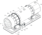
FIG. 2 is a schematic structural diagram of a drying mechanism in embodiment 1 of the present invention;
FIG. 3 is a schematic view showing a partial structure of a granulating mechanism in embodiment 1 of the present invention;
FIG. 4 is a schematic view of the internal structure of a granulating mechanism in embodiment 1 of the present invention;
fig. 5 is a schematic view of a partial structure of a drying mechanism in embodiment 1 of the present invention;
fig. 6 is a schematic front view of a drying mechanism in embodiment 1 of the present invention;
FIG. 7 isbase:Sub>A schematic cross-sectional view taken along line A-A of FIG. 6;
FIG. 8 is a schematic cross-sectional view taken along line B-B of FIG. 6;
FIG. 9 is a schematic cross-sectional view taken along line C-C of FIG. 6;
FIG. 10 is a schematic cross-sectional view taken along line D-D of FIG. 6;
FIG. 11 is a schematic diagram of the control system of the present invention;
fig. 12 is a schematic front view of a drying mechanism in embodiment 2 of the present invention;
FIG. 13 is a schematic cross-sectional view taken along line E-E of FIG. 12;
FIG. 14 is a schematic cross-sectional view taken along line F-F of FIG. 12;
FIG. 15 is a schematic cross-sectional view taken along line G-G of FIG. 12;
FIG. 16 is a schematic cross-sectional view taken along line H-H of FIG. 12;
fig. 17 is an enlarged view of region I in fig. 13.
Description of reference numerals: 1. a granulation mechanism; 11. a base; 12. a granulation sleeve; 13. a screw; 14. a screw extrusion plate; 15. a feed hopper; 16. a second drive motor; 17. a synchronous belt; 18. driving the roller; 19. a second decelerator; 110. a first prilling plate; 111. a second prilling plate; 112. a third prilling plate; 113. a fourth prilling plate; 114. a granulation cutting arm; 115. granulation through holes;
2. a drying mechanism; 21. a support; 22. drying the roller; 23. a feeding end; 24. a discharge end; 25. a ring gear; 26. a drive gear; 27. a first drive motor; 28. a first decelerator; 29. a guide support ring; 210. a support frame; 211. supporting the rollers; 212. a material guiding sleeve; 213. a discharge port; 214. a material leading-out electromagnetic valve;
3. a control system; 31. a first signal receiving module; 32. a second signal receiving module; 33. a third signal receiving module; 34. a fourth signal receiving module; 35. a first data monitoring module; 36. a second data monitoring module; 37. a first execution module; 38. a second execution module; 39. a third execution module; 310. a fourth execution module; 311. a central control module; 312. a control panel;
4. a material guiding box; 41. vibrating the material guide plate; 42. a vibration motor;
5. a hot gas flow conducting assembly; 51. installing a sleeve; 52. a hot air flow air inlet guide head; 53. hot air flow out of the gas guide head; 54. an annular air guide groove; 55. a hot gas flow supply pipe; 56. a hot gas flow delivery line; 57. a first air flow solenoid valve; 58. a second air flow solenoid valve;
6. a flow guide assembly; 61. a baffle;
7. introducing the material into the induction supporting assembly; 71. a first annular mounting plate; 72. leading in an induction supporting plate; 73. a first material sensing pressure sensor;
8. a first material drying support assembly; 81. a first mounting ring plate; 82. a first material support plate; 83. a first pressure sensor;
9. the second material drying support component; 91. a second mounting ring plate; 92. a second material support plate; 93. a second pressure sensor;
10. the material guiding induction supporting component; 101. a second annular mounting plate; 102. leading out the induction supporting plate; 103. a second material sensing pressure sensor;
100. and (4) inserting a sleeve.
Detailed Description
Example 1
As shown in fig. 1 to 5, a feed granulating and drying system comprises a granulating mechanism 1, a drying mechanism 2 connected with the granulating mechanism 1, and a control system 3, wherein the granulating mechanism 1 comprises a base 11, a granulating sleeve 12 mounted on the base 11, a screw 13 mounted in the granulating sleeve 12, a spiral extrusion plate 14 mounted on the screw 13, a feed hopper 15 mounted on the granulating sleeve 12, a granulating driving component arranged at one end of the screw 13, and a granulating forming component arranged at the other end of the screw 13; the granulation driving assembly comprises a second driving motor 16 arranged on the base 11, the second driving motor 16 is connected with a driving roller 18 through a synchronous belt 17, the driving roller 18 is connected with a second speed reducer 19, and the output end of the second speed reducer 19 is connected with the end part of the screw 13;
the granulation molding assembly comprises a first granulation plate 110, a second granulation plate 111, a third granulation plate 112, a fourth granulation plate 113 which are arranged at the end part of the inner cavity of the granulation sleeve 12 and a granulation cutting arm 114 which is fixedly arranged at the end part of the screw 13, the end part of the screw 13 penetrates through the first granulation plate 110, the second granulation plate 111, the third granulation plate 112 and the fourth granulation plate 113, the granulation cutting arm 114 is positioned at one side of the fourth granulation plate 113, and granulation through holes 115 are formed in the first granulation plate 110, the second granulation plate 111, the third granulation plate 112 and the fourth granulation plate 113;
the drying mechanism 2 comprises a bracket 21 and a drying roller 22 arranged on the bracket 21, two ends of the drying roller 22 are opened, a drying cavity is arranged in the drying roller 22, the opening end of one side of the drying roller 22 is a feeding end 23, the opening end of the other side of the drying roller 22 is a discharging end 24, and the inner diameter of the drying cavity is gradually increased from the feeding end 23 to the discharging end 24;
the support 21 is provided with a driving mechanism for controlling the drying roller 22 to rotate, and the driving mechanism comprises a gear ring 25 fixedly installed on the circumferential surface of the drying roller 22, a driving gear 26 meshed with the gear ring 25, a first driving motor 27 installed on the support 21, and a first speed reducer 28 installed between the first driving motor 27 and the driving gear 26.
A guiding support assembly is further arranged between the support 21 and the drying drum 22, the guiding support assembly comprises a guiding support ring 29 fixedly mounted on the circumferential surface of the drying drum 22, two mutually symmetrical support frames 210 fixed on the support 21, and a support roller 211 rotatably mounted on the support frames 210, and the circumferential surface of the support roller 211 is in contact with the guiding support ring 29.
The first driving motor 27 is mainly started by the control system 3, after the first driving motor 27 is started, the driving gear 26 drives the gear ring 25 to rotate, the gear ring 25 drives the drying drum 22 to rotate at a constant speed, and in the rotating process of the drying drum 22, the guide support ring 29 on the surface of the drying drum is in running fit with the support roller 211, so that the stability of the uniform speed rotation of the drying drum 22 is ensured.
In addition, a material guiding box 4 is arranged between the end part of the granulation sleeve 12 and the feeding end 23 of the drying drum 22, a vibration material guiding plate 41 is arranged in the material guiding box 4, a vibration motor 42 is arranged at the bottom of the vibration material guiding plate 41, and the bottom of the vibration material guiding plate 41 is close to the feeding end 23 of the drying drum 22.
When the granulation mechanism 1 performs granulation processing, the second driving motor 16 is started, the mixed feed raw materials are introduced into the feed hopper 15, the second driving motor 16 drives the screw 13 to rotate, the spiral extrusion plate 14 on the screw 13 conveys and extrudes the feed raw materials in the granulation sleeve 12 gradually towards the direction of the granulation forming assembly, the extruded feed raw materials sequentially pass through the first granulation plate 110, the second granulation plate 111, the third granulation plate 112 and the fourth granulation plate 113, finally form strip-shaped materials and are led out from the granulation through hole of the fourth granulation plate 113, the granulation cutting arm 114 also synchronously rotates in the rotating process of the screw 13, the granulation cutting arm 114 cuts the strip-shaped materials on one side of the fourth granulation plate 113 to form feed to be dried, the feed particles enter the material guide box 4 and are guided into the feed end 23 of the drying roller 22 along the vibration guide plate 41, the granulation mechanism 1 is connected with the drying roller 22, the granulated feed is conveniently supplied to the drying roller 22, the number of the mechanisms can be properly increased, and the number of the granulation mechanisms is determined according to the drying load of the drying roller.
Further, a hot air flow conducting assembly 5 is arranged on the drying roller 22, a guide sleeve 212 is fixedly mounted on the support 21, the discharge end 24 of the drying roller 22 is rotatably connected with the guide sleeve 212, a discharge port 213 is arranged on the guide sleeve 212, and a material guiding electromagnetic valve 214 is mounted at the discharge port 213;
a flow guide assembly 6, a material guiding induction supporting assembly 7, a first material drying supporting assembly 8, a second material drying supporting assembly 9 and a material guiding induction supporting assembly 10 are sequentially arranged on the inner wall of the drying cavity from a feeding end 23 to a discharging end 24;
wherein, the material guiding induction supporting component 7 induces the material guided into the drying roller 22, thereby controlling the driving mechanism to start;
after the first material drying support assembly 8 senses the material, the hot air flow conduction assembly 5 is controlled to be started;
after the material is sensed by the material discharging sensing support assembly 10, the material discharging solenoid valve 214 is controlled to be opened.
According to the technical scheme, the system integrates the granulating mechanism and the drying mechanism together, so that the integrated processing of processing and drying of feed particles is realized, the whole drying process is mainly controlled by the control system, and efficient drying processing is realized;
during actual processing, the granulating mechanism 1 processes feed raw materials to obtain a batch of feed particles, the feed particles are guided into the feeding end 23 of the drying roller 22, the guide assembly 6 firstly guides the feed particles into the drying cavity, the material guide induction supporting assembly 7 senses the feed particles, the control system 3 controls the driving mechanism to drive the drying roller 22 to rotate, after the drying roller 22 rotates, the feed particles in the drying roller can be primarily mixed and gradually transfer towards the direction of the discharging end 24, after the first material drying supporting assembly 8 senses the feed particles, the control system controls the hot air flow conduction assembly 5 to be opened, after the hot air flow conduction assembly 5 is opened, external hot air flow is guided into the drying cavity at a high speed, flowing hot air flow can contact with the surface of the feed particles and quickly takes away the moisture on the surface of the feed, thereby playing the purpose of drying the surface of the feed particles, when the feed particles are further transferred, after the second material drying supporting component 9 senses the feed particles, the control system 3 controls the hot air current conduction component 5 to carry out flow grade adjustment, when the feed particles further move towards the inside of the drying roller 22, after the material guiding induction supporting component 10 senses the feed particles, the control system 3 controls the material guiding electromagnetic valve 214 to open until the feed particles completely pass through the local area of the drying roller where the material guiding induction supporting component 10 is located, the guiding electromagnetic valve 214 is to guide the feed particles out, the device can sense the position of the feed particles, the drying roller 22 is automatically opened, the hot air current conduction component 5 and the material guiding electromagnetic valve 214 are automatically opened, the automatic integrated operation of drying treatment is realized, and simultaneously, the leading-in response supporting component 7 of material, first material stoving supporting component 8, second material stoving supporting component 9 and material are derived response supporting component 10 and have played the support response and link up the effect that stops to the fodder particulate matter, the fodder particulate matter can be detained longer time in the region at each supporting component place, the transfer time from feed end 23 to discharge end 24 has been prolonged to the fodder particulate matter in drying roller 22, effective stoving ageing is improved, large batch fodder particulate matter drying process can be realized to the drying roller of shorter specification, drying roller area is little, the input cost is reduced.
Further, the hot air current conduction assembly 5 comprises an installation sleeve 51 fixedly installed on the support 21, a hot air current inlet guide head 52 arranged on the installation sleeve 51, and a hot air outlet guide head 53 arranged at the top of the guide sleeve 51, the installation sleeve 51 is sleeved on the outer side of the drying roller 22, an annular air guide groove 54 communicated with the drying cavity is arranged on the drying roller 22, and the annular air guide groove 54 corresponds to the hot air current inlet guide head 52;
the hot gas inlet guiding head 52 is connected with a hot gas supply pipe 55, the hot gas outlet guiding head 53 is connected with a hot gas outlet pipe 56, a first gas flow electromagnetic valve 57 is arranged on the hot gas supply pipe 55, and a second gas flow electromagnetic valve 58 is arranged on the hot gas outlet pipe 56.
The opening and the opening time of the first air flow electromagnetic valve 57 and the second air flow electromagnetic valve 58 are mainly controlled by the control system 3, after the first material drying support assembly 8 senses the feed particles, the control system 3 controls the first air flow electromagnetic valve 57 and the second air flow electromagnetic valve 58 of the hot air flow conduction assembly to be synchronously opened, after the first air flow electromagnetic valve 57 and the second air flow electromagnetic valve 58 are synchronously opened, the hot air inlet guide head 52 guides the hot air into the drying roller 22, after the hot air is fully contacted with the feed particles, the hot air outlet guide head 53 exhausts the air flow in the drying roller 22, so that the hot air can be kept to fully flow in the drying roller 22 and be contacted with the feed particles, the equipment adopts a mode of contacting the hot air flow with the feed particles to dry the feed particles, the water evaporated by the flowing air flow can be timely conveyed out from the hot air outlet guide pipe, the drying efficiency of the equipment is higher than that of the traditional drying mode, after the hot air flow is guided into the drying roller 22, the whole drying roller 22 can be quickly filled with the feed particles, the contact with the traditional hot air flow is full, and the problem that when the traditional electric heating wire is dried, the local heating problem of the feed particles is avoided.
Further, as shown in fig. 6 to 10, the guide assembly 6 includes a plurality of guide plates 61 installed at the feeding end of the drying drum 22, and the guide plates 61 are installed to be inclined on the inner wall of the drying cavity.
The material induction support assembly 7 comprises a first annular mounting plate 71 arranged on the inner wall of the drying cavity, and a plurality of induction support plates 72 arranged on the first annular mounting plate 71, wherein the induction support plates 72 are bent, and a first material induction pressure sensor 73 is arranged on the side surface of the end part of each induction support plate 72;
the first material drying support assembly 8 comprises a first mounting ring plate 81 mounted on the inner wall of the drying cavity, and a plurality of first material support plates 82 arranged on the first mounting ring plate 81, wherein the first material support plates 82 are bent, and a first pressure sensor 83 is mounted on the side surface of the end part of each first material support plate 82;
the second material drying support assembly 9 comprises a second mounting ring plate 91 arranged on the inner wall of the drying cavity, and a plurality of second material support plates 92 arranged on the second mounting ring plate 91, wherein the second material support plates 92 are bent, and second pressure sensors 93 are arranged on the side surfaces of the end parts of the second material support plates 92;
the material guiding induction supporting assembly 10 comprises a second annular mounting plate 101 installed on the inner wall of the drying cavity, a plurality of guiding induction supporting plates 102 arranged on the second annular mounting plate 101, wherein the guiding induction supporting plates 102 are bent, and a second material induction pressure sensor 103 is installed on the side face of the end portion of each guiding induction supporting plate 102.
The number of the induction supporting plates 72 is four, the number of the first material supporting plates 82 is six, the number of the second material supporting plates 92 is six, the number of the induction supporting plates 102 is eight, the installation positions of the first material supporting plates 82 and the second material supporting plates 92 are staggered, and the staggered angle of the first material supporting plates 82 and the second material supporting plates 92 is 30-45 degrees.
In addition, the induction support plate 72, the first material support plate 82, the second material support plate 92 and the induction support plate 102 are provided with through holes for allowing the feed particles to pass through.
Through the technical scheme, the induction supporting plate 72, the first material supporting plate 82, the second material supporting plate 92 and the induction supporting plate 102 mainly play roles of supporting induction and connection blocking, feed particles can stay for a long time in the area where each supporting component is located, the transfer time of the feed particles from the feeding end to the discharging end 24 in the drying roller 22 is prolonged, and the effective drying time is improved;
the first material induction pressure sensor 73 mainly induces the fed feed particles and feeds induction signals back to the control system 3 in time, the control system 3 controls the driving mechanism to drive the drying drum 22 to rotate, the feed particles at the stage are in a pre-drying processing stage, and the rotating drying drum 22 ensures that the feed particles at the stage are in a uniform mixing state, so that the feed particles are prevented from agglomerating and caking;
the first pressure sensor 83 senses the feed particles entering the area where the first material drying support assembly 8 is located, and timely feeds back a sensing signal to the control system 3, the control system 3 controls the first airflow electromagnetic valve 57 and the second airflow electromagnetic valve 58 of the hot airflow conduction assembly 5 to be synchronously opened, after the first airflow electromagnetic valve 57 and the second airflow electromagnetic valve 58 are synchronously opened, the hot airflow inlet guide head 52 guides the hot airflow into the drying drum 22, after the hot airflow is fully contacted with the feed particles, the hot airflow outlet guide head 53 extracts the airflow in the drying drum, the feed particles at the stage are in a relatively wet state, at the moment, the first airflow electromagnetic valve 57 and the second airflow electromagnetic valve 58 are basically in a fully opened state, the hot airflow can be rapidly dried on the surface of the feed particles, and the feed particles are prevented from being agglomerated and agglomerated in the drying process;
the second pressure sensor 93 senses the feed particles entering the area where the second material drying and supporting assembly 9 is located, and timely feeds a sensing signal back to the control system 3, the control system 3 controls the air flow of the first air flow electromagnetic valve 57 and the second air flow electromagnetic valve 58 of the hot air flow conducting assembly, after the feed particles reach the stage, the interior of the feed particles needs to be dried, at this time, the drying operation enters a relatively fine stage, at this time, the first air flow electromagnetic valve 57 and the second air flow electromagnetic valve 58 are in a half-open state to be optimal, the hot air flow is relatively weakened, moisture in the feed particles can be gradually evaporated, moreover, the staggered angle of the first material supporting plate 82 and the second material supporting plate 92 is 30-45 degrees, the feed particles are transferred from the area of the first material drying and supporting assembly 8 to the area where the second material drying and after the first material supporting plate 82 and the second material supporting plate 92 are staggered relatively, the time for the feed particles to stay is long, so that the transition connection time of the feed particles from a high wind level to a low wind level is prolonged, and the problem of hot air flow suddenly reduced is avoided;
after the fodder particulate matter enters into the region where material derivation induction supporting component 10 is located, second material induction pressure sensor 103 responds to the fodder particulate matter in this region, and give control system 3 with the timely feedback of sensing signal, control system 3 control material derivation solenoid valve 214 is opened, drying drum 22 is at the uniform velocity pivoted in-process, the fodder particulate matter leads out after the region where induction supporting component 10 is located through the material, progressively derive from discharge gate 213, at this moment, the stoving process has been accomplished promptly to the fodder particulate matter.
Further, as shown in fig. 11, the control system 3 includes:
a first signal receiving module 31, configured to receive a signal of the first material sensing pressure sensor 73;
the second signal receiving module 32 is configured to receive a pressure signal of the first pressure sensor 83;
the third signal receiving module 33 is configured to receive a pressure signal of the third pressure sensor 93;
a fourth signal receiving module 34, configured to receive a signal of the second material sensing pressure sensor 103;
a first data monitoring module 35 for monitoring and recording the rotation speed of the first driving motor 27;
a second data monitoring module 36 for monitoring and recording the rotation speed of the second driving motor 16;
the first execution module 37 is used for controlling the on and off of the first driving motor 27;
the second execution module 38 is used for controlling the synchronous opening and closing of the first air flow electromagnetic valve 57 and the second air flow electromagnetic valve 58;
a third execution module 39 for controlling the flow rates of the first air flow solenoid valve 57 and the second air flow solenoid valve 58;
a fourth execution module 310, configured to control opening and closing of the material outlet solenoid valve 214;
and the central control module 311 performs logic processing on the information fed back by each signal receiving module, and sends an execution instruction to each execution module.
Wherein, be equipped with the control panel 312 that is correlated with central control module 311 signal on the drying drum 22, be equipped with the stoving mode button of two kinds of differences on the control panel 312, still be equipped with the button of the first driving motor 27 of control and the 16 rotational speeds of second driving motor simultaneously, the stoving mode button includes quantitative stoving function button and coherence loading stoving function button, the stoving mode that quantitative stoving function button corresponds is the mode that the quantitative material was dried, the stoving mode that coherence loading stoving function button corresponds is the stoving mode of coherence loading.
The following description is given with reference to specific operating procedures:
the processing technology of the feed granulating and drying system comprises the following steps:
s1, granulating the mixed feed raw materials by a granulating mechanism 1, and introducing the processed feed particles into a feed port 23 of a drying roller 22;
s2, the guide assembly 6 guides the feed particles into a drying cavity of the drying drum 22;
s3, after the material introduction induction supporting component 7 induces the feed particles, the control system controls the driving mechanism to drive the drying roller 22 to rotate;
s4, after the first material drying supporting assembly 8 senses the feed particles, the control system controls the hot air flow conducting assembly 5 to be started;
s5, after the second material drying and supporting component 9 senses the feed particles, the control system controls the hot air flow conducting component 5 to adjust the flow grade;
s6, after the material discharging induction support assembly 10 induces the feed particles, the control system controls the material discharging electromagnetic valve 214 to be opened.
The working principle of the present application is explained in detail below with reference to two different drying modes:
the first mode is as follows: quantitative material drying mode
After the granulating mechanism 1 is started, the produced feed particles enter the material guide box 4 and are guided into the feed end 23 of the drying roller 22 along the vibration material guide plate 41, because the mode is a quantitative material drying mode, after the weight of the feed particles guided into the drying roller 22 meets the set requirement, the granulating mechanism 1 stops working, then the drying operation is performed, during the drying operation, firstly, the feed particles are guided into the area where the induction support component 7 is located by the guide plate 61, the first material induction pressure sensor 73 of the material induction support component 7 mainly induces the feed particles after being fed, and feeds induction signals back to the first signal receiving module 31 in time, the central control module 311 controls the first driving motor 16 of the driving mechanism to start through the first execution module 37, the first driving motor 16 drives the drying roller 22 to rotate, the feed particles at the stage are at the pre-drying processing stage, and the rotating drying roller 22 ensures that the feed particles at the stage are in a uniform mixing state, thereby avoiding the feed particles from agglomerating and caking;
because the inner diameter of the drying cavity of the drying drum 22 gradually increases from the feeding end to the discharging end, in the process of gradually rotating the drying drum, the feed particles are gradually transferred from the feeding end 23 to the discharging end 24, when the feed particles are transferred to the area where the first material drying support assembly 8 is located, the first pressure sensor 83 senses the feed particles entering the area where the first material drying support assembly 8 is located, and feeds sensing signals back to the second signal receiving module 32 in time, the central control module 311 controls the first airflow electromagnetic valve 57 and the second airflow electromagnetic valve 58 of the hot airflow conducting assembly 5 to be synchronously opened through the second execution module 38, after the first airflow electromagnetic valve 57 and the second airflow electromagnetic valve 58 are synchronously opened, the hot airflow inlet guide head 52 guides the hot airflow into the drying drum 22, the hot airflow is fully contacted with the feed particles, the hot airflow outlet guide head 53 draws the airflow in the drying drum 22, the feed particles in the stage are in a relatively humid state, at this time, the first airflow electromagnetic valve 57 and the second airflow electromagnetic valve 58 are basically in a fully opened state, the hot airflow can draw the surface of the hot airflow to prevent the feed particles from being rapidly agglomerated in the drying process;
further, when the feed particles enter the area where the second material drying and supporting assembly 9 is located, the second pressure sensor 93 senses the feed particles entering the area where the second material drying and supporting assembly 9 is located, and timely feeds a sensing signal to the third signal receiving module 33, the central control module 311 controls the first airflow electromagnetic valve 57 and the second airflow electromagnetic valve 58 of the hot airflow conduction assembly to be in an open state of 1/2 through the third execution module 39, after the feed particles reach the stage, the interior of the feed particles needs to be dried, at the moment, the drying operation enters a relatively fine stage, at the moment, the first airflow electromagnetic valve 57 and the second airflow electromagnetic valve 58 are in a half-open state which is optimal, the amount of hot airflow is relatively weakened, and moisture in the feed particles can be gradually evaporated;
further, fodder particulate matter enters into the material and derives the regional back that response supporting component 10 is located, second material response pressure sensor 103 responds to the fodder particulate matter in this region, and give the fourth signal reception module 34 with the timely feedback of sensing signal, central control module 311 controls the material through fourth execution module 310 and derives solenoid valve 214 and open, drying drum 22 is at the in-process of uniform velocity pivoted, the fodder particulate matter derives the regional back that response supporting component 10 is located through the material, derive gradually from discharge gate 213, at this moment, the stoving process procedure has been accomplished to the fodder particulate matter promptly.
And a second mode: consistency feeding and drying mode
The difference between this mode and the first mode is that, during the processing, the granulation mechanism 1 and the drying drum 22 both work synchronously, the granulation mechanism 1 continuously conveys the feed particles to the drying drum 22, and after the control panel 312 is set to the continuous feeding and drying mode, after the first pressure sensor 83 and the second pressure sensor 93 sense the feed particles, the second execution module 38 and the third execution module 39 both control the first air flow electromagnetic valve 57 and the second air flow electromagnetic valve 58 to be always in the 2/3 on state, when the feed particles are conveyed to the area where the first material drying and supporting component 8 and the second material drying and supporting component 9 are located, the amount of hot air flow of the drying drum 22 is unchanged, the drying mode of this area is greatly different from the quantitative material drying mode, mainly because when the feed particles are conveyed in the drying drum 22, the continuous feeding of the feed particles needs to ensure that the feed particles of the previous and subsequent batches are in a relatively stable drying temperature environment, therefore, when the feed particles are conveyed to the area where the first material drying and supporting component 8 and the second material drying and supporting component 9 are located, the amount of the feed particles is the same as the feeding of the feed particles after the continuous feeding and the quantitative material drying and supporting component, and the feeding of the feed particles into the area after the continuous feeding and the quantitative material drying and the feeding and supporting component.
In addition, the control system 3 is further provided with a first data monitoring module 35 and a second data monitoring module 36, wherein the first data monitoring module 35 monitors and records the rotation speed data of the first driving motor 16 of the drying drum 22, the second data monitoring module 36 monitors and records the rotation speed data of the second driving motor 27 of the granulating mechanism, under the normal condition, the rotation speed of the drying drum driven by the first driving motor 16 is set to be 5 rpm, the rotation speed of the screw driven by the second driving motor 27 is set to be 20 rpm, under the condition that the hot air quantity supply quantity is not changed, in the embodiment, one drying drum is only provided with one granulating mechanism, under the condition of continuous feeding, if more granulating mechanisms are put in or the rotation speed of the screw is increased, the quantity of the feed particles entering the drying drum is increased, because the control panel 312 is provided with a button for controlling the rotation speeds of the first driving motor 16 and the second driving motor 27, at this time, the rotation speed of the first driving motor 16 is increased by a button manually, and the rotation speed of the second driving motor is decreased by a centrifugal force, so that the drying efficiency of the drying drum 22 is increased and the drying efficiency is decreased appropriately balanced by a centrifugal force.
Example 2
As shown in fig. 12 to 17, the present embodiment is different from embodiment 1 in that lengths of the induction support plate 72, the first material support plate 82, the second material support plate 92 and the induction support plate 102 can be adjusted freely, the induction support plate 72, the first material support plate 82, the second material support plate 92 and the induction support plate 102 are all provided with the insertion sleeve 100, for example, when the induction support plate 72 needs to be lengthened, two induction support plates 72 are inserted into the insertion sleeve 100, and a corresponding sensor is installed at a free end of the second induction support plate 72, the insertion sleeve 100 is added to facilitate changing lengths of the induction support plate 72, the first material support plate 82, the second material support plate 92 and the induction support plate 102, because feed particles inside the drying drum 22 are mainly moved gradually from an inner wall to a middle part during rotation, the induction support plate 72, the first material support plate 82, the second material support plate 92 and the induction support plate 102 is longer, pressure sensors installed thereon are relatively more sensitive, and better in blocking effect on the feed particles, and the induction support plate 7 is also more sensitive, and the induction support assembly can be designed to facilitate induction support the induction support of a plurality of induction support components 7 and induction support the induction support components 9 and induction support the induction support components 7, and improve the induction support components.
In conclusion, the device can sense the position of feed particles, automatically turn on the drying roller 22, automatically turn on the hot air flow conduction assembly 5 and the material guiding solenoid valve 214, and realize the automatic integrated operation of drying treatment, meanwhile, the material guiding induction support assembly 7, the first material drying support assembly 8, the second material drying support assembly 9 and the material guiding induction support assembly 10 play a role in supporting induction and linking blocking the feed particles, the feed particles can stay for a longer time in the area where each support assembly is located, the transfer time of the feed particles from the feeding end to the discharging end in the drying roller is prolonged, the effective drying time is improved, the drying roller with a shorter specification can realize the drying treatment of large batch of feed particles, the floor area of the drying roller is small, and the investment cost is reduced;
the device dries the feed particles by adopting a mode of contacting hot air flow with the feed particles, the flowing air flow can timely bring out moisture evaporated by the feed particles from a hot air flow outlet pipe, the drying efficiency is higher than that of the traditional electric heating wire drying mode, after the hot air flow is guided into the drying roller, the whole drying roller can be quickly filled with the hot air flow, the hot air flow is fully contacted with the feed particles, and the problem that the feed particles are locally heated when the traditional electric heating wire drying treatment is carried out is also avoided;
this system can realize the switching of ration material stoving mode and continuity material loading stoving mode, and control system can carry out real time monitoring to the operation rotational speed of granulation mechanism and drying roller 22, and when granulation mechanism's granulation speed changed, the inside temperature of drying roller 22 and the length of time of drying can carry out the adaptability and adjust, have improved fodder particulate matter's stoving treatment precision and efficiency.
The foregoing shows and describes the general principles, essential features, and advantages of the invention. It will be understood by those skilled in the art that the present invention is not limited to the embodiments described above, which are merely illustrative of the principles of the invention, but that various changes and modifications may be made without departing from the spirit and scope of the invention, which fall within the scope of the invention as claimed. The scope of the invention is defined by the appended claims and equivalents thereof.
Claims (10)
1. A granulating and drying system for feed comprises a granulating mechanism (1), a drying mechanism (2) and a control system (3), wherein the drying mechanism (2) is connected with the granulating mechanism (1), the drying mechanism (2) comprises a support (21), a drying roller (22) is installed on the support (21), two ends of the drying roller (22) are opened, a drying cavity is formed in the drying roller (22), the opening end of one side of the drying roller (22) is a feeding end (23), the opening end of the other side of the drying roller is a discharging end (24), and the inner diameter of the drying cavity is gradually increased from the feeding end (23) to the discharging end (24);
a driving mechanism for controlling the drying roller (22) to rotate is arranged on the support (21), a hot air flow conduction assembly (5) is arranged on the drying roller (22), a material guide sleeve (212) is fixedly mounted on the support (21), a discharge end (24) of the drying roller (22) is rotatably connected with the material guide sleeve (212), a discharge hole (213) is formed in the material guide sleeve (212), and a material guide electromagnetic valve (214) is mounted at the discharge hole (213);
a flow guide assembly (6) is sequentially arranged on the inner wall of the drying cavity from a feeding end (23) to a discharging end (24), a material guiding induction supporting assembly (7), a first material drying supporting assembly (8), a second material drying supporting assembly (9) and a material guiding induction supporting assembly (10) are arranged;
the material guiding induction supporting component (7) induces the material guided into the drying roller (22) so as to control the driving mechanism to start;
after the first material drying support assembly (8) senses the material, the hot air flow conducting assembly (5) is controlled to be started;
after the material is induced by the material induction supporting component (10), the material induction electromagnetic valve (214) is controlled to be opened.
2. The feed granulating and drying system according to claim 1, wherein the hot air flow conducting assembly (5) comprises a mounting sleeve (51) fixedly mounted on the support (21), a hot air flow inlet guide head (52) arranged on the mounting sleeve (51), and a hot air flow outlet guide head (53) arranged at the top of the guide sleeve (212), the mounting sleeve (51) is sleeved on the outer side of the drying drum (22), an annular air guide groove (54) communicated with the drying cavity is arranged on the drying drum (22), and the annular air guide groove (54) corresponds to the hot air flow inlet guide head (52);
the hot air flow inlet guide head (52) is connected with a hot air flow supply pipe (55), the hot air flow outlet guide head (53) is connected with a hot air flow outlet pipe (56), a first air flow electromagnetic valve (57) is installed on the hot air flow supply pipe (55), and a second air flow electromagnetic valve (58) is installed on the hot air flow outlet pipe (56).
3. A fodder pelletizing and drying system according to claim 1, characterized in that the deflector assembly (6) comprises a plurality of deflectors (61) mounted at the feed end (23) of the drying drum (22), the deflectors (61) being mounted inclined on the inner wall of the drying cavity.
4. The feed granulating and drying system according to claim 2, wherein the material induction support assembly (7) comprises a first annular mounting plate (71) mounted on the inner wall of the drying cavity, a plurality of induction support plates (72) arranged on the first annular mounting plate (71), the induction support plates (72) are bent, and a first material induction pressure sensor (73) is mounted on the side surface of the end part of each induction support plate (72);
the first material drying support assembly (8) comprises a first mounting ring plate (81) mounted on the inner wall of the drying cavity, and a plurality of first material support plates (82) arranged on the first mounting ring plate (81), wherein the first material support plates (82) are bent, and a first pressure sensor (83) is mounted on the side surface of the end part of each first material support plate (82);
the second material drying support assembly (9) comprises a second mounting ring plate (91) mounted on the inner wall of the drying cavity, and a plurality of second material support plates (92) arranged on the second mounting ring plate (91), wherein the second material support plates (92) are bent, and second pressure sensors (93) are mounted on the side surfaces of the ends of the second material support plates (92);
the material derivation induction supporting assembly (10) comprises a second annular mounting plate (101) arranged on the inner wall of the drying cavity, a plurality of derivation induction supporting plates (102) arranged on the second annular mounting plate (101), the derivation induction supporting plates (102) are bent, and second material induction pressure sensors (103) are arranged on the side faces of the ends of the derivation induction supporting plates (102).
5. The feed granulating and drying system according to claim 4, wherein the number of the induction support plates (72) is four, the number of the first material support plates (82) and the second material support plates (92) is six, the number of the induction support plates (102) is eight, the installation positions of the first material support plates (82) and the second material support plates (92) are staggered, and the staggered angle of the first material support plates (82) and the second material support plates (92) is 30-45 degrees;
the induction supporting plate (72), the first material supporting plate (82), the second material supporting plate (92) and the induction supporting plate (102) are provided with through holes for feed particles to pass through.
6. A fodder granulating and drying system as claimed in claim 4, wherein said drive mechanism includes a toothed ring (25) fixedly mounted on the peripheral surface of said drying drum (22), a drive gear (26) engaged with said toothed ring (25), a first drive motor (27) mounted on said support (21), and a first decelerator (28) mounted between said first drive motor (27) and said drive gear (26).
7. The feed granulating and drying system of claim 6, wherein a guide support assembly is further arranged between the support (21) and the drying drum (22), the guide support assembly comprises a guide support ring (29) fixedly mounted on the circumferential surface of the drying drum (22), two mutually symmetrical support frames (210) fixed on the support (21), and a support roller (211) rotatably mounted on the support frames (210), and the circumferential surface of the support roller (211) is in contact with the guide support ring (29).
8. A fodder granulating and drying system as claimed in claim 6, wherein the granulating mechanism (1) comprises a base (11), a granulating sleeve (12) mounted on the base (11), a screw (13) mounted in the granulating sleeve (12), a screw extrusion plate (14) mounted on the screw (13), a feed hopper (15) mounted on the granulating sleeve (12), a granulating driving component arranged at one end of the screw (13), and a granulating forming component arranged at the other end of the screw (13);
the granulation driving assembly comprises a second driving motor (16) arranged on the base (11), the second driving motor (16) is connected with a driving roller (18) through a synchronous belt (17), the driving roller (18) is connected with a second speed reducer (19), and the output end of the second speed reducer (19) is connected with the end part of the screw (13);
the granulation forming assembly comprises a first granulation plate (110), a second granulation plate (111), a third granulation plate (112), a fourth granulation plate (113) and a granulation cutting arm (114) fixedly mounted at the end part of the screw (13), the end part of the screw (13) penetrates through the first granulation plate (110), the second granulation plate (111), the third granulation plate (112) and the fourth granulation plate (113), the granulation cutting arm (114) is positioned at one side of the fourth granulation plate (113), and granulation through holes (115) are formed in the first granulation plate (110), the second granulation plate (111), the third granulation plate (112) and the fourth granulation plate (113);
a material guiding box (4) is arranged between the end part of the granulating sleeve (12) and the feeding end (23) of the drying roller (22), a vibration material guiding plate (41) is arranged in the material guiding box (4), a vibration motor (42) is installed at the bottom of the vibration material guiding plate (41), and the bottom of the vibration material guiding plate (42) is close to the feeding end (23) of the drying roller (22).
9. A system for pelletizing and drying fodder according to claim 8, characterized in that said control system (3) comprises:
a first signal receiving module (31) for receiving a signal of the first material sensing pressure sensor (73);
a second signal receiving module (32) for receiving a pressure signal of the first pressure sensor (83);
a third signal receiving module (33) for receiving a pressure signal of the third pressure sensor (93);
a fourth signal receiving module (34) for receiving a signal of the second material sensing pressure sensor (103);
the first data monitoring module (35) is used for monitoring and recording the rotating speed of the first driving motor (27);
the second data monitoring module (36) is used for monitoring and recording the rotating speed of the second driving motor (16);
the first execution module (37) is used for controlling the opening and closing of the first driving motor (27);
the second execution module (38) is used for controlling the first air flow electromagnetic valve (57) and the second air flow electromagnetic valve (58) to be opened and closed synchronously;
a third execution module (39) for controlling the flow of the first and second air flow solenoid valves (57, 58);
the fourth execution module (310) is used for controlling the opening and closing of the material leading-out electromagnetic valve (214);
and the central control module (311) is used for carrying out logic processing on the information fed back by each signal receiving module and sending an execution instruction to each execution module.
10. The processing technology of the feed granulating and drying system based on claim 1 is characterized by comprising the following steps:
s1, a granulating mechanism (1) performs granulating processing on the mixed feed raw materials, and the processed feed particles are guided into a feeding port (23) of a drying roller (22);
s2, the flow guide assembly (6) guides the feed particles into a drying cavity of the drying drum (22);
s3, after the material is guided into the induction supporting assembly (7) to induce the feed particles, the control system (3) controls the driving mechanism to drive the drying roller (22) to rotate;
s4, after the first material drying support assembly (8) senses the feed particles, the control system (3) controls the hot air flow conduction assembly (5) to be started;
s5, after the second material drying and supporting assembly (9) senses the feed particles, the control system (3) controls the hot air flow conducting assembly (5) to adjust the flow grade;
s6, after the material discharging induction supporting assembly (10) induces the feed particles, the control system (3) controls the material discharging electromagnetic valve (214) to be opened.
Priority Applications (1)
| Application Number | Priority Date | Filing Date | Title |
|---|---|---|---|
| CN202211270015.0A CN115540532A (en) | 2022-10-18 | 2022-10-18 | Feed granulating and drying system and process |
Applications Claiming Priority (1)
| Application Number | Priority Date | Filing Date | Title |
|---|---|---|---|
| CN202211270015.0A CN115540532A (en) | 2022-10-18 | 2022-10-18 | Feed granulating and drying system and process |
Publications (1)
| Publication Number | Publication Date |
|---|---|
| CN115540532A true CN115540532A (en) | 2022-12-30 |
Family
ID=84735643
Family Applications (1)
| Application Number | Title | Priority Date | Filing Date |
|---|---|---|---|
| CN202211270015.0A Pending CN115540532A (en) | 2022-10-18 | 2022-10-18 | Feed granulating and drying system and process |
Country Status (1)
| Country | Link |
|---|---|
| CN (1) | CN115540532A (en) |
Citations (14)
| Publication number | Priority date | Publication date | Assignee | Title |
|---|---|---|---|---|
| CN1410398A (en) * | 2001-09-25 | 2003-04-16 | 深圳市先科环保有限公司 | Method of producing organic composite fertilizer using organic sludge and its equipment |
| CN202902832U (en) * | 2012-10-23 | 2013-04-24 | 溧阳市永立农牧机械有限公司 | Cylinder for cylinder drying machine |
| CN103245178A (en) * | 2013-05-28 | 2013-08-14 | 机械科学研究总院先进制造技术研究中心 | Automatic drying unit and use method thereof |
| CN205843280U (en) * | 2016-06-17 | 2016-12-28 | 中民筑友科技投资有限公司 | A kind of air-dry apparatus |
| CN206269522U (en) * | 2016-11-29 | 2017-06-20 | 重庆丰兴源生态农业发展有限公司 | Organic fertilizer dryer |
| CN207371492U (en) * | 2017-10-30 | 2018-05-18 | 黑龙江牧康牧业有限责任公司 | Fertilizer molding granulation machine |
| CN207540318U (en) * | 2017-10-18 | 2018-06-26 | 贵溪市樟坪供销合作社 | A kind of ganoderma lucidum processing drying equipment |
| CN207556088U (en) * | 2017-09-21 | 2018-06-29 | 河北祁一堂药业有限公司 | The high tunnel type micro wave drying equipment of safety coefficient |
| CN112856971A (en) * | 2021-01-25 | 2021-05-28 | 太原科技大学 | Coal slime dryer variable frequency speed regulation control system and control method |
| CN213416708U (en) * | 2020-10-16 | 2021-06-11 | 海口华农生物肥料有限公司 | Novel bio-organic fertilizer granulation device |
| CN112958441A (en) * | 2021-03-15 | 2021-06-15 | 厦门穆寒科技有限公司 | Raw material drying device is used in production of living beings pellet fuel |
| CN215337437U (en) * | 2021-07-27 | 2021-12-28 | 石家庄中吉化肥有限公司 | Granular potash fertilizer drying roller |
| CN114279189A (en) * | 2021-12-27 | 2022-04-05 | 盛大勇 | Production and preparation process of environment-friendly straw pellet feed |
| CN217473456U (en) * | 2022-07-04 | 2022-09-23 | 开原市嬴德肉禽有限责任公司 | Granulating device for chicken feed |
-
2022
- 2022-10-18 CN CN202211270015.0A patent/CN115540532A/en active Pending
Patent Citations (14)
| Publication number | Priority date | Publication date | Assignee | Title |
|---|---|---|---|---|
| CN1410398A (en) * | 2001-09-25 | 2003-04-16 | 深圳市先科环保有限公司 | Method of producing organic composite fertilizer using organic sludge and its equipment |
| CN202902832U (en) * | 2012-10-23 | 2013-04-24 | 溧阳市永立农牧机械有限公司 | Cylinder for cylinder drying machine |
| CN103245178A (en) * | 2013-05-28 | 2013-08-14 | 机械科学研究总院先进制造技术研究中心 | Automatic drying unit and use method thereof |
| CN205843280U (en) * | 2016-06-17 | 2016-12-28 | 中民筑友科技投资有限公司 | A kind of air-dry apparatus |
| CN206269522U (en) * | 2016-11-29 | 2017-06-20 | 重庆丰兴源生态农业发展有限公司 | Organic fertilizer dryer |
| CN207556088U (en) * | 2017-09-21 | 2018-06-29 | 河北祁一堂药业有限公司 | The high tunnel type micro wave drying equipment of safety coefficient |
| CN207540318U (en) * | 2017-10-18 | 2018-06-26 | 贵溪市樟坪供销合作社 | A kind of ganoderma lucidum processing drying equipment |
| CN207371492U (en) * | 2017-10-30 | 2018-05-18 | 黑龙江牧康牧业有限责任公司 | Fertilizer molding granulation machine |
| CN213416708U (en) * | 2020-10-16 | 2021-06-11 | 海口华农生物肥料有限公司 | Novel bio-organic fertilizer granulation device |
| CN112856971A (en) * | 2021-01-25 | 2021-05-28 | 太原科技大学 | Coal slime dryer variable frequency speed regulation control system and control method |
| CN112958441A (en) * | 2021-03-15 | 2021-06-15 | 厦门穆寒科技有限公司 | Raw material drying device is used in production of living beings pellet fuel |
| CN215337437U (en) * | 2021-07-27 | 2021-12-28 | 石家庄中吉化肥有限公司 | Granular potash fertilizer drying roller |
| CN114279189A (en) * | 2021-12-27 | 2022-04-05 | 盛大勇 | Production and preparation process of environment-friendly straw pellet feed |
| CN217473456U (en) * | 2022-07-04 | 2022-09-23 | 开原市嬴德肉禽有限责任公司 | Granulating device for chicken feed |
Similar Documents
| Publication | Publication Date | Title |
|---|---|---|
| US4511093A (en) | Mixer-granulator drier | |
| CN108013488A (en) | A kind of multifunctional feed granulation device | |
| CN215063243U (en) | Wet granule drying machine of fluidized bed | |
| CN108816471B (en) | Energy-concerving and environment-protective type rice processing equipment | |
| CN115540532A (en) | Feed granulating and drying system and process | |
| CN108113031A (en) | A kind of feed mixing granulation device with functions/drying | |
| CN208653121U (en) | A kind of drum-type drying device | |
| CN206565272U (en) | Feed Manufacturing granulator | |
| CN108030126A (en) | A kind of quick mixing granulation device of feed with polishing | |
| CN112902638A (en) | Closed-loop intelligent tea drying method and drying machine | |
| JP4566442B2 (en) | Continuous powder dryer | |
| CN211379583U (en) | Be used for integrative equipment of aquatic products fodder stoving pelletization | |
| CN219674597U (en) | Drying device is used in feed production processing | |
| CN218600174U (en) | Drying equipment is used in drier processing | |
| CN215983714U (en) | Drying device is used in dog grain production | |
| CN214371595U (en) | Closed loop type intelligence tealeaves desiccator | |
| CN206583254U (en) | Feed Manufacturing High-efficiency dryer | |
| CN211261680U (en) | Balanced meal drying device of cereal | |
| CN204911289U (en) | An auxiliary material that dries in air adds machine | |
| CN219313783U (en) | Feed processing is with loading attachment | |
| CN208739852U (en) | A kind of coaxial annular hopper material transfering device | |
| CN112304074A (en) | Feed pellet drying-machine | |
| CN219433581U (en) | Particle cooling system for pig feed production | |
| CN209116704U (en) | A kind of circulating rice dryer of small intelligent | |
| CN213735834U (en) | Feed mechanism of feed packaging machine |
Legal Events
| Date | Code | Title | Description |
|---|---|---|---|
| PB01 | Publication | ||
| PB01 | Publication | ||
| SE01 | Entry into force of request for substantive examination | ||
| SE01 | Entry into force of request for substantive examination |