CN115338571A - Steel structure welding equipment and method - Google Patents
Steel structure welding equipment and method Download PDFInfo
- Publication number
- CN115338571A CN115338571A CN202211003828.3A CN202211003828A CN115338571A CN 115338571 A CN115338571 A CN 115338571A CN 202211003828 A CN202211003828 A CN 202211003828A CN 115338571 A CN115338571 A CN 115338571A
- Authority
- CN
- China
- Prior art keywords
- steel bars
- reinforcing steel
- rotating
- welding
- gear
- Prior art date
- Legal status (The legal status is an assumption and is not a legal conclusion. Google has not performed a legal analysis and makes no representation as to the accuracy of the status listed.)
- Granted
Links
- 238000003466 welding Methods 0.000 title claims abstract description 91
- 229910000831 Steel Inorganic materials 0.000 title claims abstract description 86
- 239000010959 steel Substances 0.000 title claims abstract description 86
- 238000000034 method Methods 0.000 title claims abstract description 10
- 230000000087 stabilizing effect Effects 0.000 claims abstract description 15
- 229910001294 Reinforcing steel Inorganic materials 0.000 claims description 79
- 230000005540 biological transmission Effects 0.000 claims description 36
- 230000003014 reinforcing effect Effects 0.000 claims description 18
- 230000006835 compression Effects 0.000 claims description 4
- 238000007906 compression Methods 0.000 claims description 4
- 238000005096 rolling process Methods 0.000 claims description 2
- 238000010276 construction Methods 0.000 claims 1
- 239000007787 solid Substances 0.000 claims 1
- 238000009434 installation Methods 0.000 description 3
- 230000003068 static effect Effects 0.000 description 2
- 230000009286 beneficial effect Effects 0.000 description 1
- 230000007547 defect Effects 0.000 description 1
- 230000000694 effects Effects 0.000 description 1
- 238000004880 explosion Methods 0.000 description 1
- 239000002360 explosive Substances 0.000 description 1
- 239000000463 material Substances 0.000 description 1
Images


Classifications
-
- B—PERFORMING OPERATIONS; TRANSPORTING
- B23—MACHINE TOOLS; METAL-WORKING NOT OTHERWISE PROVIDED FOR
- B23K—SOLDERING OR UNSOLDERING; WELDING; CLADDING OR PLATING BY SOLDERING OR WELDING; CUTTING BY APPLYING HEAT LOCALLY, e.g. FLAME CUTTING; WORKING BY LASER BEAM
- B23K37/00—Auxiliary devices or processes, not specially adapted to a procedure covered by only one of the preceding main groups
- B23K37/02—Carriages for supporting the welding or cutting element
- B23K37/0247—Driving means
-
- B—PERFORMING OPERATIONS; TRANSPORTING
- B23—MACHINE TOOLS; METAL-WORKING NOT OTHERWISE PROVIDED FOR
- B23K—SOLDERING OR UNSOLDERING; WELDING; CLADDING OR PLATING BY SOLDERING OR WELDING; CUTTING BY APPLYING HEAT LOCALLY, e.g. FLAME CUTTING; WORKING BY LASER BEAM
- B23K37/00—Auxiliary devices or processes, not specially adapted to a procedure covered by only one of the preceding main groups
- B23K37/04—Auxiliary devices or processes, not specially adapted to a procedure covered by only one of the preceding main groups for holding or positioning work
- B23K37/053—Auxiliary devices or processes, not specially adapted to a procedure covered by only one of the preceding main groups for holding or positioning work aligning cylindrical work; Clamping devices therefor
-
- B—PERFORMING OPERATIONS; TRANSPORTING
- B23—MACHINE TOOLS; METAL-WORKING NOT OTHERWISE PROVIDED FOR
- B23K—SOLDERING OR UNSOLDERING; WELDING; CLADDING OR PLATING BY SOLDERING OR WELDING; CUTTING BY APPLYING HEAT LOCALLY, e.g. FLAME CUTTING; WORKING BY LASER BEAM
- B23K2103/00—Materials to be soldered, welded or cut
- B23K2103/02—Iron or ferrous alloys
- B23K2103/04—Steel or steel alloys
-
- Y—GENERAL TAGGING OF NEW TECHNOLOGICAL DEVELOPMENTS; GENERAL TAGGING OF CROSS-SECTIONAL TECHNOLOGIES SPANNING OVER SEVERAL SECTIONS OF THE IPC; TECHNICAL SUBJECTS COVERED BY FORMER USPC CROSS-REFERENCE ART COLLECTIONS [XRACs] AND DIGESTS
- Y02—TECHNOLOGIES OR APPLICATIONS FOR MITIGATION OR ADAPTATION AGAINST CLIMATE CHANGE
- Y02P—CLIMATE CHANGE MITIGATION TECHNOLOGIES IN THE PRODUCTION OR PROCESSING OF GOODS
- Y02P70/00—Climate change mitigation technologies in the production process for final industrial or consumer products
- Y02P70/10—Greenhouse gas [GHG] capture, material saving, heat recovery or other energy efficient measures, e.g. motor control, characterised by manufacturing processes, e.g. for rolling metal or metal working
Abstract
The invention provides steel structure welding equipment and a method, which comprises a fixed cylinder, a feeding end, a feeding stabilizing mechanism, a rotating cylinder, an annular guide block, a fixed frame, an annular guide groove, a handheld fixed rod, a rotating device, a mounting plate, a welding gun, a fixed plate, a fastening bolt and a positioning device, wherein the fixed cylinder is arranged in two sections, and the two fixed cylinders have the same structure.
Description
Technical Field
The invention relates to the technical field of steel structure welding, in particular to steel structure welding equipment and a steel structure welding method.
Background
The steel structure engineering is one of the more ordinary structural style in modern building engineering, wherein the material that uses in the steel structure is various, there are reinforcing bar and steel pipe etc., the form of connection has welding, riveting, bolted connection etc., when welding the reinforcing bar in steel structure engineering, some weld two reinforcing bars placing subaerial, some need carry out one section concatenation to the reinforcing bar of having installed on the building, because do not have the kind equipment that welds the reinforcing bar in the mill specially, consequently people can only hand welder manual weld the reinforcing bar, but when welding two reinforcing bars subaerial, because the alignment position of reinforcing bar can only people manually be surveyd, consequently can't guarantee welded integrality, cause the junction of steel structure to appear welding defect, even when carrying out one section concatenation to the reinforcing bar of having installed on the building, because do not have the flat ground can support the reinforcing bar, people hold more difficult centering position of two sections reinforcing bars, more influenced people's welding effect to the reinforcing bar.
Therefore, it is necessary to provide a steel structure welding device and method to solve the above technical problems.
Disclosure of Invention
In order to solve the technical problems, the invention provides steel structure welding equipment and a steel structure welding method, which can perform centering welding on two steel bars on the ground or the steel bars already installed on a building.
The invention provides steel structure welding equipment which comprises a fixed cylinder, a feeding end, a feeding stabilizing mechanism, a rotating cylinder, an annular guide block, a fixed frame, an annular guide groove, a handheld fixed rod, a rotating device, a mounting plate, a welding gun, a fixed plate, a fastening bolt and a positioning device, wherein the fixed cylinder is arranged in two sections, the two fixed cylinders are same in structure, one end of the fixed cylinder is provided with the feeding end, the position of the fixed cylinder, which corresponds to the feeding end, is provided with the feeding stabilizing mechanism for fixing and feeding a steel bar, the rotating cylinder is rotatably arranged in one end of the fixed cylinder, which is far away from the feeding end, the annular guide block is symmetrically and fixedly arranged on the outer side of the rotating cylinder, the fixed frame is fixedly arranged on the inner wall of the fixed cylinder, which corresponds to the position of the annular guide block, the position of the inner part of the fixed frame, which corresponds to the position of the annular guide block, is provided with the annular guide groove, and is rotatably connected with the annular guide block, a hand-held fixed rod is symmetrically and fixedly arranged between the two fixed cylinders and used for connecting the two fixed cylinders, a rotating device used for rotating the rotating cylinder is fixedly arranged between the outer sides of the two fixed cylinders and comprises a fixed frame, a transmission rod, a driven gear, a motor, a driving gear, a first bevel gear and a second bevel gear, a fixed frame is fixedly arranged between the outer sides of the two fixed cylinders, the transmission rod is rotatably arranged in the top end of the fixed frame through a bearing, the driven gear is fixedly arranged in the middle of the transmission rod, the motor is fixedly arranged in the middle of the top end of the fixed frame, the driving gear is fixedly arranged at the output end of the motor and meshed with the driven gear, the first bevel gear and the second bevel gear are respectively and fixedly arranged at the two ends of the transmission rod, a mounting plate is fixedly arranged at the position corresponding to the welding position of the steel bar between the two fixed cylinders, and a welding gun for welding the steel bar is arranged in the middle of the mounting plate, the mounting panel corresponds the position symmetry fixed mounting of welder has the fixed plate, and the mid-mounting of fixed plate has fastening bolt, and the mid-mounting of rotary drum has and is used for carrying out spacing positioner to the reinforcing bar. When splicing two reinforcing steel bars on the ground or splicing the reinforcing steel bars installed on a building for one section, inserting the two reinforcing steel bars into two ends of two fixed cylinders respectively, realizing stable feeding of the two reinforcing steel bars through a feeding stabilizing mechanism, moving the joint of the two reinforcing steel bars to a position between the two fixed cylinders, namely corresponding to the position of a welding gun, driving the welding gun to slide in the middle of an installation plate by screwing a fastening bolt when welding the reinforcing steel bars with different diameters, moving a gun head of the welding gun to the position of a standard welding reinforcing steel bar, reversely screwing the fastening bolt to realize the fixing of the position of the welding gun by the fastening bolt, and then fixing the two reinforcing steel bars through a positioning device.
Preferably, the feeding stabilizing mechanism comprises a first positioning hole, a first positioning column, a first anti-falling block, a first spring and rollers, wherein the first positioning hole is symmetrically formed in one end of the fixed cylinder, the first positioning column is slidably mounted in the middle of the first positioning hole, the first anti-falling block is fixedly mounted at one end of the first positioning column, the first spring is sleeved on the outer side of the other end of the first positioning column, one end of the first spring is fixedly connected with the inner wall of the fixed cylinder, the other end of the first spring is fixedly connected with one end, far away from the first anti-falling block, of the first positioning column, the rollers are mounted at one end, far away from the first anti-falling block, the reinforcing steel bar is moved to the positions among the six rollers, when the reinforcing steel bars with different diameters are welded, the reinforcing steel bar is extruded to drive the rollers to slide along the track of the first positioning column, the first spring is always in a compressed state at the moment, the six rollers are driven to extrude the reinforcing steel bar through reverse acting force of the first spring, and stable feeding of the two sections of the reinforcing steel bars is realized.
Preferably, the rotating device further comprises a gear ring, connecting plates, rotating rods, third bevel gears, fourth bevel gears, through holes, rotating shafts, fifth bevel gears and transmission gears, the connecting plates are symmetrically and fixedly installed on two sides of the fixing frame, the rotating rods are rotatably installed between the two connecting plates through bearings, third bevel gears are fixedly installed on the tops of the two rotating rods, the two third bevel gears are respectively meshed with the first bevel gear and the second bevel gear, the fourth bevel gears are fixedly installed on the bottoms of the rotating rods, the through holes are formed in the positions, corresponding to the fourth bevel gears, of the fixing cylinders, the rotating shafts are rotatably installed in the middle of the fixing cylinders corresponding to the through holes through the bearings, the fifth bevel gears are fixedly installed in the middle of the rotating shafts and meshed with the fourth bevel gears, the transmission gears are fixedly installed at one ends of the rotating shafts, the gear rings are fixedly installed on the outer sides of the rotating cylinders corresponding to the positions of the transmission gears, the gear rings are meshed with the transmission gears, when the reinforcing steel bars are welded, people hold the fixing rods with hands, the motors are opened, the rotating cylinders are driven to rotate along tracks of the annular guide grooves, the reinforcing steel bars, relative stillness relative to drive the rotating of the welding guns, and realize the welding of the reinforcing steel bars.
Preferably, the motor is a geared motor. Providing a strong torque for the operation of the motor.
Preferably, the positioning device comprises a second positioning hole, a second positioning column, a second anti-falling block, a second spring and balls, the second positioning hole is symmetrically formed in the middle of the rotating cylinder, the second positioning column is slidably mounted in the middle of the second positioning hole, the second anti-falling block is fixedly mounted at one end of the second positioning column, the second spring is sleeved on the outer side of the other end of the second positioning column, one end of the second spring is fixedly connected with the inner wall of the rotating cylinder, the other end of the second spring is fixedly connected with the other end of the second positioning column, the ball is mounted at one end, away from the second anti-falling block, of the second positioning column in a rolling manner. When the reinforcing steel bars with different diameters are welded, the reinforcing steel bars extrude the balls to drive the second positioning column to slide along the track of the second positioning hole, the second spring is always in a compressed state, the six balls are driven by the reverse acting force of the second spring to extrude the reinforcing steel bars, and the fixing of two sections of reinforcing steel bars is realized.
Preferably, the second positioning hole and the second positioning column, and the first positioning hole and the first positioning column are tightly attached to each other and slide. The stability of the second positioning column along the second positioning hole and the stability of the first positioning column along the first positioning hole are realized.
Preferably, a rubber pad is arranged on the outer side of the hand-held fixed rod. The comfort level of people holding the fixing rod is improved.
The scheme also comprises a steel structure welding method, which comprises the following steps:
s1, when splicing two steel bars on the ground or splicing a section of steel bar installed on a building, inserting the two steel bars into two ends of two fixed cylinders respectively, moving the steel bars to a position between six rollers, when welding the steel bars with different diameters, extruding the rollers by the steel bars, driving a first positioning column to slide along a track of a first positioning hole, enabling a first spring to be in a compressed state all the time, driving the six rollers to extrude the steel bars by reverse acting force of the first spring, so as to realize stable feeding of the two sections of steel bars, then moving a joint of the two sections of steel bars to a position between the two fixed cylinders, namely the position corresponding to a welding gun, and meanwhile, when welding the steel bars with different diameters, driving the welding gun to slide in the middle of an installation plate by screwing the fastening bolt, moving a gun head of the welding gun to the position of a standard welding steel bar, and then reversely screwing the fastening bolt, so as to realize fixing of the gun position of the fastening bolt;
s2, when feeding the steel bars, moving the steel bars to six balls in the same manner, extruding the balls by the steel bars when welding the steel bars with different diameters, driving the second positioning column to slide along the track of the second positioning hole, keeping the second spring in a compressed state, and driving the six balls to extrude the steel bars through the reverse acting force of the second spring to fix two sections of the steel bars;
s3, when the reinforcing steel bar is welded, a user holds the fixed rod by hand, the motor is turned on to operate, the driving gear is driven to rotate, the driving gear is meshed with the driven gear to drive the transmission rod to rotate, the first bevel gear and the second bevel gear are driven to rotate, the two third bevel gears are respectively meshed with the first bevel gear and the second bevel gear to drive the two rotating rods to rotate, the fourth bevel gear is driven to rotate, the rotating shaft is driven to rotate by meshing of the fifth bevel gear and the fourth bevel gear to drive the transmission gear to rotate, the rotating cylinder is driven to rotate along the track of the annular guide groove by meshing of the gear ring and the transmission gear, the welding gun is driven to rotate around the outer side of the reinforcing steel bar, and the reinforcing steel bar is welded;
and S4, after welding is finished, the steel bars are drawn out of the device or the device slides out along the outer sides of the steel bars.
Compared with the related art, the invention has the following beneficial effects:
when the steel bar welding device is used, compared with the prior art, two steel bars are respectively inserted into two ends of two fixed cylinders, the steel bars are moved to positions between six rollers, when the steel bars with different diameters are welded, the steel bars extrude the rollers to drive the first positioning column to slide along the track of the first positioning hole, at the moment, the first spring is always in a compression state, the six rollers are driven to extrude the steel bars through the reverse acting force of the first spring, so that stable feeding of the two sections of steel bars is realized, when the steel bars are fed, the steel bars move to positions between the six balls, the steel bars extrude the balls to drive the second positioning column to slide along the track of the second positioning hole, at the moment, the second spring is always in the compression state, the six balls are driven to extrude the steel bars through the reverse acting force of the second spring, the feeding and stabilizing mechanism are matched with each other, so that the two sections of steel bars are fixed, and the fixed structure between the fixed cylinders can ensure that the two steel bars are arranged in a centered manner;
when welding the reinforcing bar, people hold handheld dead lever, and the orbit that drives through rotating device's function and rotate along annular guide slot of a rotating cylinder has guaranteed the reinforcing bar for this device position is static relatively, and then drives the rotation of welder around the reinforcing bar outside, realizes the welding to the reinforcing bar.
Drawings
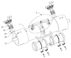
FIG. 1 is a schematic view of the overall structure of the present invention;
FIG. 2 is a schematic cross-sectional view of the present invention;
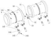
FIG. 3 is a schematic illustration of an explosive structure according to the present invention;
FIG. 4 is an enlarged view taken at A in FIG. 3;
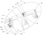
fig. 5 is a schematic view of a partial explosion structure of the present invention.
Reference numbers in the figures: 1. a fixed cylinder; 2. a feeding end; 3. a feeding stabilizing mechanism; 4. a rotating drum; 5. an annular guide block; 6. a fixing frame; 7. an annular guide groove; 8. a fixed rod is held by hand; 9. a rotating device; 10. mounting a plate; 11. a welding gun; 12. a fixing plate; 13. fastening a bolt; 14. a positioning device; 31. a first positioning hole; 32. a first positioning post; 33. a first anti-drop block; 34. a first spring; 35. a roller; 91. a fixed mount; 92. a transmission rod; 93. a gear ring; 94. a driven gear; 95. a motor; 96. a driving gear; 97. a first bevel gear; 98. a second bevel gear; 99. a connecting plate; 910. a rotating rod; 911. a third bevel gear; 912. a fourth bevel gear; 913. a through hole; 914. a rotating shaft; 915. a fifth bevel gear; 916. a transmission gear; 141. a second positioning hole; 142. a second positioning column; 143. a second anti-drop block; 144. a second spring; 145. and (4) a ball.
Detailed Description
The invention is further described with reference to the following figures and embodiments.
Referring to fig. 1 to 5, a steel structure welding device includes a fixed cylinder 1, a feeding end 2, a feeding stabilizing mechanism 3, a rotating cylinder 4, an annular guide block 5, a fixed frame 6, an annular guide groove 7, a handheld fixed rod 8, a rotating device 9, a mounting plate 10, a welding gun 11, a fixed plate 12, a fastening bolt 13 and a positioning device 14, wherein the fixed cylinder 1 is provided with two sections, the two fixed cylinders 1 have the same structure, the feeding end 2 is provided at one end of the fixed cylinder 1, the feeding stabilizing mechanism 3 for fixing and feeding steel bars is provided at a position of the fixed cylinder 1 corresponding to the feeding end 2, the rotating cylinder 4 is rotatably provided inside one end of the fixed cylinder 1 far from the feeding end 2, the annular guide block 5 is symmetrically and fixedly provided at the outer side of the rotating cylinder 4, the fixed frame 6 is fixedly provided at a position of the inner wall of the fixed cylinder 1 corresponding to the annular guide block 5, the annular guide groove 7 is provided inside the fixed cylinder 6 corresponding to the annular guide block 5, the annular guide groove 7 is rotatably connected with the annular guide block 5, a handheld fixing rod 8 for connecting the two fixed cylinders 1 is symmetrically and fixedly arranged between the two fixed cylinders 1, a rotating device 9 for rotating the rotating cylinder 4 is fixedly arranged between the outer sides of the two fixed cylinders 1, the rotating device 9 comprises a fixed frame 91, a transmission rod 92, a driven gear 94, a motor 95, a driving gear 96, a first bevel gear 97 and a second bevel gear 98, the fixed frame 91 is fixedly arranged between the outer sides of the two fixed cylinders 1, the transmission rod 92 is rotatably arranged inside the top end of the fixed frame 91 through a bearing, the driven gear 94 is fixedly arranged in the middle of the transmission rod 92, the motor 95 is fixedly arranged in the middle of the top end of the fixed frame 91, the driving gear 96 is fixedly arranged at the output end of the motor 95, and the driving gear 96 is meshed with the driven gear 94, the two ends of the transmission rod 92 are respectively and fixedly provided with a first bevel gear 97 and a second bevel gear 98, a mounting plate 10 is fixedly arranged between the two fixing cylinders 1 corresponding to the welding position of the steel bar, a welding gun 11 for welding the steel bar is arranged in the middle of the mounting plate 10, fixing plates 12 are fixedly arranged on the mounting plate 10 corresponding to the welding gun 11 in a symmetrical mode, fastening bolts 13 are arranged in the middle of the fixing plates 12, and a positioning device 14 for limiting the steel bar is arranged in the middle of the rotating cylinder 4. Meanwhile, when the reinforcing steel bars with different diameters are welded, the fastening bolt 13 is screwed to drive the welding gun 11 to slide in the middle of the mounting plate 10, the gun head of the welding gun 11 is moved to the position of a standard welding reinforcing steel bar, then the fastening bolt 13 is screwed reversely to fix the position of the welding gun 11 by the fastening bolt 13, when two reinforcing steel bars or reinforcing steel bars which are already installed on a building are spliced on the ground, the two reinforcing steel bars are respectively inserted into two ends of two fixing cylinders 1, stable feeding of the two reinforcing steel bars is realized through the feeding stabilizing mechanism 3, then the joint of the two reinforcing steel bars is moved to a position between the two fixing cylinders 1, namely the position of the welding gun 11 corresponds to the position of the welding gun 11, and then the two reinforcing steel bars are fixed through the positioning device 14, and the operation of the rotating device 9 is controlled to drive the welding gun 11 to rotate around the outer side of the reinforcing steel bars, so that the welding of the reinforcing steel bars is realized.
Please refer to fig. 1 to 5 in combination, the feeding stabilizing mechanism 3 includes a first positioning hole 31, a first positioning column 32, a first anti-falling block 33, a first spring 34 and a roller 35, the first positioning hole 31 is symmetrically formed at one end of the fixed cylinder 1, the first positioning column 32 is slidably mounted at the middle of the first positioning hole 31, the first anti-falling block 33 is fixedly mounted at one end of the first positioning column 32, the first spring 34 is sleeved at the outer side of the other end of the first positioning column 32, one end of the first spring 34 is fixedly connected with the inner wall of the fixed cylinder 1, the other end of the first spring 34 is fixedly connected with one end of the first positioning column 32 far away from the first anti-falling block 33, and the roller 35 is mounted at one end of the first positioning column 32 far away from the first anti-falling block 33. When splicing two reinforcing steel bars on the ground or splicing the reinforcing steel bars installed on a building, the two reinforcing steel bars are respectively inserted into two ends of the two fixed cylinders 1, the reinforcing steel bars are moved to positions between the six rollers 35, when the reinforcing steel bars with different diameters are welded, the rollers 35 are extruded by the reinforcing steel bars, the first positioning column 32 is driven to slide along the track of the first positioning hole 31, the first spring 34 is always in a compression state at the moment, the six rollers 35 are driven to extrude the reinforcing steel bars by the reverse acting force of the first spring 34, and stable feeding of the two reinforcing steel bars is achieved.
Referring to fig. 1 to 5, the rotating device 9 further includes a gear ring 93, a connecting plate 99, a rotating rod 910, a third bevel gear 911, a fourth bevel gear 912, a through hole 913, a rotating shaft 914, a fifth bevel gear 915 and a transmission gear 916, the connecting plates 99 are symmetrically and fixedly installed on two sides of the fixing frame 91, the rotating rod 910 is rotatably installed between the two connecting plates 99 through a bearing, the third bevel gear 911 is fixedly installed on the tops of the two rotating rods 910, the two third bevel gears 911 are respectively engaged with the first bevel gear 97 and the second bevel gear 98, the fourth bevel gear 912 is fixedly installed on the bottom of the rotating rod 910, the through hole 913 is installed in the fixing cylinder 1 at a position corresponding to the fourth bevel gear 912, the rotating shaft 914 is rotatably installed in the middle of the fixing cylinder 1 corresponding to the through hole 913 through a bearing, the fifth bevel gear is fixedly installed in the middle of the rotating shaft 914 915, the fifth bevel gear 915 is engaged with the fourth bevel gear 912, the transmission gear 916 is fixedly installed at one end of the rotating shaft 914, the gear ring 93 is fixedly installed on the outer side of the rotating cylinder 4 corresponding to the transmission gear 916, and the gear ring 93 is engaged with the transmission gear 916. When welding the reinforcing steel bar, a user holds the hand-held fixing rod 8, opens the motor 95 to operate, and further drives the driving gear 96 to rotate, the driving gear 96 is meshed with the driven gear 94 to drive the transmission rod 92 to rotate, and further drives the first bevel gear 97 and the second bevel gear 98 to rotate, because the two third bevel gears 911 are respectively meshed with the first bevel gear 97 and the second bevel gear 98, the two rotating rods 910 are driven to rotate, and further drives the fourth bevel gear 912 to rotate, the rotating shaft 914 is driven to rotate through the meshing of the fifth bevel gear 915 and the fourth bevel gear 912, and further drives the transmission gear 916 to rotate, and the rotating cylinder 4 is driven to rotate along the track of the annular guide groove 7 through the meshing of the gear ring 93 and the transmission gear 916, so that the position of the reinforcing steel bar relative to the device is ensured to be relatively static, and further drives the welding gun 11 to rotate around the outer side of the reinforcing steel bar, and the welding of the reinforcing steel bar is realized.
Referring to fig. 1 to 5, the motor 95 is a speed reduction motor. Providing a strong torque for the operation of the motor 95.
Referring to fig. 1 to fig. 5, the positioning device 14 includes a second positioning hole 141, a second positioning column 142, a second anti-falling block 143, a second spring 144 and a ball 145, the second positioning hole 141 is symmetrically formed in the middle of the rotating cylinder 4, the second positioning column 142 is slidably mounted in the middle of the second positioning hole 141, the second anti-falling block 143 is fixedly mounted at one end of the second positioning column 142, the second spring 144 is sleeved outside the other end of the second positioning column 142, one end of the second spring 144 is fixedly connected to the inner wall of the rotating cylinder 4, the other end of the second spring 144 is fixedly connected to one end of the second positioning column 142 away from the second anti-falling block 143, and the ball 145 is rotatably mounted at one end of the second positioning column 142 away from the second anti-falling block 143. When the steel bar is fed, the steel bar moves to the position between the six balls 145, the steel bar extrudes the balls 145 to drive the second positioning column 142 to slide along the track of the second positioning hole 141, at the moment, the second spring 144 is always in a compressed state, the six balls 145 are driven by the reverse acting force of the second spring 144 to extrude the steel bar, the steel bar is matched with the feeding stabilizing mechanism 3, the fixing of two sections of steel bars is realized, and the two steel bars can be ensured to be in a centering arrangement due to the fact that the fixing structure is arranged between the fixing cylinders 1.
Referring to fig. 1 to fig. 5, the second positioning hole 141 and the second positioning post 142, and the first positioning hole 31 and the first positioning post 32 are tightly attached to each other and slide. The stability of the second positioning post 142 along the second positioning hole 141 and the stability of the first positioning post 32 along the first positioning hole 31 are achieved.
Referring to fig. 1 to 5, a rubber pad is installed on the outer side of the hand-held fixing rod 8. The comfort level of people holding the fixing rod 8 by hands is improved.
The scheme also comprises a steel structure welding method, which comprises the following steps:
s1, when splicing two reinforcing steel bars on the ground or a reinforcing steel bar installed on a building, inserting the two reinforcing steel bars at two ends of two fixed cylinders 1 respectively, moving the reinforcing steel bars to positions between six rollers 35, when welding reinforcing steel bars with different diameters, extruding the rollers 35 by the reinforcing steel bars, driving a first positioning column 32 to slide along the track of a first positioning hole 31, enabling a first spring 34 to be in a compressed state all the time, driving the six rollers 35 to extrude the reinforcing steel bars by reverse acting force of the first spring 34, realizing stable feeding of the two reinforcing steel bars, then moving a joint of the two reinforcing steel bars to a position between the two fixed cylinders 1, namely the position corresponding to a welding gun 11, and when welding reinforcing steel bars with different diameters, driving the welding gun 11 to slide in the middle of an installation plate 10 by screwing a fastening bolt 13, moving a gun head of the welding gun 11 to the position of a standard welded reinforcing steel bar, and then reversely screwing the fastening bolt 13, so as to realize fixing of the position of the welding gun 11 by the fastening bolt 13;
s2, when feeding the steel bars, in the same manner as the above, the steel bars move to the position between the six balls 145, when welding the steel bars with different diameters, the steel bars extrude the balls 145 to drive the second positioning column 142 to slide along the track of the second positioning hole 141, at the moment, the second spring 144 is always in a compressed state, and the six balls 145 are driven by the reverse acting force of the second spring 144 to extrude the steel bars, so that the two sections of the steel bars are fixed;
s3, when the reinforcing steel bar is welded, a user holds the fixing rod 8 by hand, turns on the motor 95 to operate, and further drives the driving gear 96 to rotate, the driving gear 96 is meshed with the driven gear 94 to drive the transmission rod 92 to rotate, and further drives the first bevel gear 97 and the second bevel gear 98 to rotate, as the two third bevel gears 911 are respectively meshed with the first bevel gear 97 and the second bevel gear 98, the two rotating rods 910 are driven to rotate, and further drives the fourth bevel gear 912 to rotate, the rotating shaft 914 is driven to rotate through the meshing of the fifth bevel gear 915 and the fourth bevel gear 912, and further drives the transmission gear 916 to rotate, the rotating cylinder 4 is driven to rotate along the track of the annular guide groove 7 through the meshing of the gear ring 93 and the transmission gear 916, and further drives the welding gun 11 to rotate around the outer side of the reinforcing steel bar, so that the reinforcing steel bar is welded;
and S4, after welding is finished, the steel bars are drawn out of the device or the device slides out along the outer sides of the steel bars.
The above description is only an embodiment of the present invention, and is not intended to limit the scope of the present invention, and all equivalent structures or equivalent processes performed by the present invention or directly or indirectly applied to other related technical fields are included in the scope of the present invention.
Claims (8)
1. The utility model provides a steel construction welding equipment, its characterized in that, including solid fixed cylinder (1), feed end (2), pay-off stabilizing mean (3), a rotating cylinder (4), annular guide block (5), fixed frame (6), annular guide slot (7), handheld dead lever (8), rotating device (9), mounting panel (10), welder (11), fixed plate (12), fastening bolt (13) and positioner (14), gu fixed cylinder (1) is two sections settings, two the structure of gu fixed cylinder (1) is the same, feed end (2) have been seted up to the one end of gu fixed cylinder (1), gu fixed cylinder (1) corresponds the position of feed end (2) and installs pay-off stabilizing mean (3) that are used for fixed and pay-off to the reinforcing bar, gu fixed cylinder (1) is kept away from the inside rotation of one end of feed end (2) and is installed rotating cylinder (4), the outside symmetry fixed mounting of rotating cylinder (4) has annular guide block (5), the inner wall of gu fixed cylinder (1) corresponds the position fixed mounting of annular guide block (5) has annular guide block (6), the inside of fixed cylinder (6) corresponds the annular guide block (5) and has seted up the position of annular guide block (7) and is used for annular guide slot (7) between two fixed cylinder (1) and rotating cylinder (7), be used for annular guide slot (1) and rotating cylinder (7) are connected annular guide block (1), and annular guide block (7) are connected A handheld fixing rod (8) is connected, a rotating device (9) used for rotating the rotating cylinder (4) is fixedly installed between the outer sides of the two fixing cylinders (1), the rotating device (9) comprises a fixing frame (91), a transmission rod (92), a driven gear (94), a motor (95), a driving gear (96), a first bevel gear (97) and a second bevel gear (98), the fixing frame (91) is fixedly installed between the outer sides of the two fixing cylinders (1), the transmission rod (92) is installed inside the top end of the fixing frame (91) in a rotating mode through a bearing, the driven gear (94) is fixedly installed in the middle of the transmission rod (92), the motor (95) is fixedly installed in the middle of the top end of the fixing frame (91), the driving gear (96) is fixedly installed at the output end of the motor (95), the driving gear (96) is connected with the driven gear (94) in a meshing mode, the first bevel gear (97) and the second bevel gear (98) are fixedly installed at two ends of the transmission rod (92) respectively, a mounting plate (10) is fixedly installed at a position corresponding to a welding position of a steel bar welding position, a mounting plate (11) is installed between the two fixing cylinders (1), and a welding gun (12) is symmetrically installed on the mounting plate (11), the middle part of the fixed plate (12) is provided with a fastening bolt (13), and the middle part of the rotating cylinder (4) is provided with a positioning device (14) for limiting the reinforcing steel bars.
2. The steel structure welding equipment according to claim 1, characterized in that the feeding stabilizing mechanism (3) comprises a first positioning hole (31), a first positioning column (32), a first anti-falling block (33), a first spring (34) and a roller (35), wherein the first positioning hole (31) is symmetrically formed in one end of the fixed cylinder (1), the first positioning column (32) is slidably mounted in the middle of the first positioning hole (31), the first anti-falling block (33) is fixedly mounted at one end of the first positioning column (32), the first spring (34) is sleeved outside the other end of the first positioning column (32), one end of the first spring (34) is fixedly connected with the inner wall of the fixed cylinder (1), the other end of the first spring (34) is fixedly connected with one end, far away from the first anti-falling block (33), of the first positioning column (32) is far away from the first anti-falling block (33), and the roller (35) is mounted at one end, far away from the first anti-falling block (33).
3. The steel structure welding equipment according to claim 1, wherein the rotating device (9) further comprises a gear ring (93), connecting plates (99), rotating rods (910), third bevel gears (911), fourth bevel gears (912), through holes (913), a rotating shaft (914), fifth bevel gears (915) and transmission gears (916), the connecting plates (99) are symmetrically and fixedly installed on two sides of the fixing frame (91), the rotating rods (910) are installed between the two connecting plates (99) through bearings in a rotating mode, the third bevel gears (911) are installed on the tops of the two rotating rods (910) in a fixed mode, the two third bevel gears (911) are respectively connected with the first bevel gear (97) and the second bevel gear (98) in a meshed mode, the fourth bevel gear (912) is fixedly installed at the bottom of the rotating rod (910), the through holes (913) are formed in the fixing cylinder (1) at positions corresponding to the fourth bevel gears (912) in the fixing cylinder (1), the rotating shaft (914) is installed in the middle of the fixing cylinder (1) corresponding to the through the bearings, the fifth bevel gear (914) is fixedly installed in the middle of the rotating shaft (914), and one end of the fifth bevel gear (914) is connected with the transmission gears (916), a gear ring (93) is fixedly arranged at the position, corresponding to the transmission gear (916), of the outer side of the rotating cylinder (4), and the gear ring (93) is meshed and connected with the transmission gear (916).
4. A steel structure welding apparatus according to claim 1, characterized in that said motor (95) is a speed reduction motor.
5. The steel structure welding equipment according to claim 1, wherein the positioning device (14) comprises a second positioning hole (141), a second positioning column (142), a second anti-falling block (143), a second spring (144) and balls (145), the second positioning hole (141) is symmetrically formed in the middle of the rotating cylinder (4), the second positioning column (142) is slidably mounted in the middle of the second positioning hole (141), the second anti-falling block (143) is fixedly mounted at one end of the second positioning column (142), the second spring (144) is sleeved outside the other end of the second positioning column (142), one end of the second spring (144) is fixedly connected with the inner wall of the rotating cylinder (4), the other end of the second spring (144) is fixedly connected with one end, far away from the second anti-falling block (143), of the second positioning column (142) is provided with the balls (145) in a rolling manner, and the other end, far away from the second anti-falling block (143), of the second positioning column (142).
6. The steel structure welding equipment as recited in claim 5, characterized in that the second positioning hole (141) and the second positioning column (142) and the first positioning hole (31) and the first positioning column (32) are tightly attached, attached and slid.
7. The steel structure welding equipment as claimed in claim 1, characterized in that the outside of the hand-held fixing rod (8) is provided with a rubber pad.
8. A steel structure welding method is characterized by comprising the following steps:
s1, when splicing two reinforcing steel bars on the ground or splicing reinforcing steel bars installed on a building for one section, inserting the two reinforcing steel bars into two ends of two fixing cylinders (1) respectively, moving the reinforcing steel bars to positions between six rollers (35), and when welding the reinforcing steel bars with different diameters, extruding the rollers (35) by the reinforcing steel bars to drive a first positioning column (32) to slide along the track of a first positioning hole (31), wherein a first spring (34) is always in a compressed state, the six rollers (35) are driven by the reverse acting force of the first spring (34) to extrude the reinforcing steel bars, so that stable feeding of the two sections of reinforcing steel bars is realized, then moving the joint of the two sections of reinforcing steel bars to positions between the two fixing cylinders (1), namely the positions corresponding to welding guns (11), and meanwhile, when welding the reinforcing steel bars with different diameters, driving the welding guns (11) to slide in the middle of a mounting plate (10) by screwing the fastening bolts (13), moving the gun heads of the welding guns (11) to the positions of standard welding steel bars, and then reversely screwing the fastening bolts (13) to realize the positions of the fixing bolts (11);
s2, when the reinforcing steel bar is fed, the reinforcing steel bar moves to the position between the six balls (145) in the same manner, when the reinforcing steel bars with different diameters are welded, the reinforcing steel bar extrudes the balls (145) to drive the second positioning column (142) to slide along the track of the second positioning hole (141), at the moment, the second spring (144) is always in a compression state, the six balls (145) are driven to extrude the reinforcing steel bar through the reverse acting force of the second spring (144), and the two sections of reinforcing steel bars are fixed;
s3, when welding the reinforcing steel bar, a user holds the fixing rod (8) by hand, the motor (95) is started to operate, the driving gear (96) is driven to rotate, the driving rod (92) is driven to rotate through meshing of the driving gear (96) and the driven gear (94), the first bevel gear (97) and the second bevel gear (98) are driven to rotate, the two rotating rods (910) are driven to rotate due to the fact that the two third bevel gears (911) are respectively in meshing connection with the first bevel gear (97) and the second bevel gear (98), the fourth bevel gear (912) is driven to rotate, the rotating shaft (914) is driven to rotate through meshing of the fifth bevel gear (915) and the fourth bevel gear (912), the transmission gear (916) is driven to rotate along the track of the annular guide groove (7), the welding gun (11) is driven to rotate around the outer side of the reinforcing steel bar, and welding of the reinforcing steel bar is achieved;
and S4, after welding is finished, the steel bars are drawn out of the device or the device slides out along the outer sides of the steel bars.
Priority Applications (1)
| Application Number | Priority Date | Filing Date | Title |
|---|---|---|---|
| CN202211003828.3A CN115338571B (en) | 2022-08-22 | 2022-08-22 | Steel structure welding equipment and method |
Applications Claiming Priority (1)
| Application Number | Priority Date | Filing Date | Title |
|---|---|---|---|
| CN202211003828.3A CN115338571B (en) | 2022-08-22 | 2022-08-22 | Steel structure welding equipment and method |
Publications (2)
| Publication Number | Publication Date |
|---|---|
| CN115338571A true CN115338571A (en) | 2022-11-15 |
| CN115338571B CN115338571B (en) | 2024-03-08 |
Family
ID=83954823
Family Applications (1)
| Application Number | Title | Priority Date | Filing Date |
|---|---|---|---|
| CN202211003828.3A Active CN115338571B (en) | 2022-08-22 | 2022-08-22 | Steel structure welding equipment and method |
Country Status (1)
| Country | Link |
|---|---|
| CN (1) | CN115338571B (en) |
Cited By (2)
| Publication number | Priority date | Publication date | Assignee | Title |
|---|---|---|---|---|
| CN117259610A (en) * | 2023-11-10 | 2023-12-22 | 邯郸富鑫达建材科技有限公司 | Straightening butt welding device and butt welding method for coiled steel bars |
| CN117718652A (en) * | 2024-02-18 | 2024-03-19 | 江苏新迅达不锈钢制品有限公司 | Stainless steel screw welding device |
Citations (15)
| Publication number | Priority date | Publication date | Assignee | Title |
|---|---|---|---|---|
| KR100999942B1 (en) * | 2010-07-15 | 2010-12-13 | 웰텍 주식회사 | Internal line up clamp device of steel pipes and pipe line connecting method in construction site |
| CN108436382A (en) * | 2018-05-31 | 2018-08-24 | 郑州靓岛建筑设计有限公司 | A kind of construction site heating and ventilating pipeline welding fixture |
| CN208214613U (en) * | 2018-05-22 | 2018-12-11 | 天津市军大钢铁股份有限公司 | A kind of movable type steel pipe welder |
| CN111112865A (en) * | 2019-12-30 | 2020-05-08 | 谭宁 | Steel pipe welding device |
| CN111531295A (en) * | 2020-05-07 | 2020-08-14 | 许琳 | Welding device for stainless steel pipes |
| CN111604345A (en) * | 2020-07-09 | 2020-09-01 | 谢丐养 | Reusable protective device and method for production and processing of combined type steel bars |
| CN211759562U (en) * | 2019-12-25 | 2020-10-27 | 泰州市艾瑞克新型材料有限公司 | Automatic welding device for sleeved unequal-diameter circular tubes |
| CN212552527U (en) * | 2020-05-09 | 2021-02-19 | 杭州亚客金属制造有限公司 | Auxiliary clamping device for butt welding of round pipes |
| CN213163816U (en) * | 2020-09-23 | 2021-05-11 | 张雯 | Raw material welding equipment for processing metal building materials |
| CN113001094A (en) * | 2021-02-25 | 2021-06-22 | 青岛北船管业有限责任公司 | Steel pipe concentric pressing and welding device |
| CN214558503U (en) * | 2021-03-08 | 2021-11-02 | 上海倍庭家居科技有限公司 | Bathroom hardware welding device |
| CN113634968A (en) * | 2021-09-02 | 2021-11-12 | 杨雪锋 | Welding equipment for slide rail type building construction and use method thereof |
| CN215699382U (en) * | 2021-06-09 | 2022-02-01 | 成都金嵘智能装备技术有限公司 | Welding robot for processing pressure container |
| CN215699408U (en) * | 2021-09-23 | 2022-02-01 | 浙江大地钢结构有限公司 | Clamp for welding steel pipe of building steel structure |
| CN215846546U (en) * | 2021-10-18 | 2022-02-18 | 辽河石油勘探局有限公司 | Oil gas long-distance pipeline welding device with correction function |
-
2022
- 2022-08-22 CN CN202211003828.3A patent/CN115338571B/en active Active
Patent Citations (15)
| Publication number | Priority date | Publication date | Assignee | Title |
|---|---|---|---|---|
| KR100999942B1 (en) * | 2010-07-15 | 2010-12-13 | 웰텍 주식회사 | Internal line up clamp device of steel pipes and pipe line connecting method in construction site |
| CN208214613U (en) * | 2018-05-22 | 2018-12-11 | 天津市军大钢铁股份有限公司 | A kind of movable type steel pipe welder |
| CN108436382A (en) * | 2018-05-31 | 2018-08-24 | 郑州靓岛建筑设计有限公司 | A kind of construction site heating and ventilating pipeline welding fixture |
| CN211759562U (en) * | 2019-12-25 | 2020-10-27 | 泰州市艾瑞克新型材料有限公司 | Automatic welding device for sleeved unequal-diameter circular tubes |
| CN111112865A (en) * | 2019-12-30 | 2020-05-08 | 谭宁 | Steel pipe welding device |
| CN111531295A (en) * | 2020-05-07 | 2020-08-14 | 许琳 | Welding device for stainless steel pipes |
| CN212552527U (en) * | 2020-05-09 | 2021-02-19 | 杭州亚客金属制造有限公司 | Auxiliary clamping device for butt welding of round pipes |
| CN111604345A (en) * | 2020-07-09 | 2020-09-01 | 谢丐养 | Reusable protective device and method for production and processing of combined type steel bars |
| CN213163816U (en) * | 2020-09-23 | 2021-05-11 | 张雯 | Raw material welding equipment for processing metal building materials |
| CN113001094A (en) * | 2021-02-25 | 2021-06-22 | 青岛北船管业有限责任公司 | Steel pipe concentric pressing and welding device |
| CN214558503U (en) * | 2021-03-08 | 2021-11-02 | 上海倍庭家居科技有限公司 | Bathroom hardware welding device |
| CN215699382U (en) * | 2021-06-09 | 2022-02-01 | 成都金嵘智能装备技术有限公司 | Welding robot for processing pressure container |
| CN113634968A (en) * | 2021-09-02 | 2021-11-12 | 杨雪锋 | Welding equipment for slide rail type building construction and use method thereof |
| CN215699408U (en) * | 2021-09-23 | 2022-02-01 | 浙江大地钢结构有限公司 | Clamp for welding steel pipe of building steel structure |
| CN215846546U (en) * | 2021-10-18 | 2022-02-18 | 辽河石油勘探局有限公司 | Oil gas long-distance pipeline welding device with correction function |
Cited By (2)
| Publication number | Priority date | Publication date | Assignee | Title |
|---|---|---|---|---|
| CN117259610A (en) * | 2023-11-10 | 2023-12-22 | 邯郸富鑫达建材科技有限公司 | Straightening butt welding device and butt welding method for coiled steel bars |
| CN117718652A (en) * | 2024-02-18 | 2024-03-19 | 江苏新迅达不锈钢制品有限公司 | Stainless steel screw welding device |
Also Published As
| Publication number | Publication date |
|---|---|
| CN115338571B (en) | 2024-03-08 |
Similar Documents
| Publication | Publication Date | Title |
|---|---|---|
| CN115338571A (en) | Steel structure welding equipment and method | |
| CN114918593B (en) | Automatic welding device and welding method for steel pipe | |
| CN113399901B (en) | Tubular pile welding vehicle with locking track capable of being assembled and disassembled quickly | |
| CN113967819B (en) | Self-adjusting welding roller frame | |
| CN111843324B (en) | Crawling welding robot for connecting oil and gas long-distance pipeline | |
| CN111872607A (en) | Production device and production method of insulated galvanized steel sheet | |
| CN111075204B (en) | Construction method for mounting reinforced concrete precast beam | |
| CN116921945B (en) | Power transmission line platform assembling and welding device | |
| DE4243529C2 (en) | Device for internal processing of pipes or channels | |
| CN109434270B (en) | Static double-shaft-shoulder friction stir welding stirring head with auxiliary rope pulling device and method for welding butt weld | |
| CN111940934B (en) | General microwave antenna automatic welding device | |
| CN108543837B (en) | A kind of high quality veneer reeling machine | |
| CN217775833U (en) | Horizontal girth welding device | |
| CN217253011U (en) | Drilling equipment is used in aeroengine shell processing | |
| CN115341911A (en) | Auxiliary fixing device for steel sleeve of shield tunneling machine | |
| CN115722858A (en) | Welding jig and welding machine | |
| CN212886021U (en) | Barrel interfacing apparatus | |
| CN110877322B (en) | Automatic screwing device for prestressed reinforced nut matched with hollow jack | |
| DE4311365A1 (en) | Mobile appts. for internal machining of pipes or ducts - incorporates three DC motors enabling console to rotate and move radially during advance along axis of pipe | |
| CN109773397B (en) | Welding positioner for steel reinforcement cage | |
| CN108543846B (en) | Telescopic rotating arm mechanism for winding pipe | |
| CN209754236U (en) | TIG welding equipment for circumferential welding | |
| CN111677288A (en) | Quick screwing device for steel bar splicing sleeve | |
| CN102500234B (en) | Purifier metal carrier core winding machine | |
| CN218396765U (en) | Turning device for machining steel structure |
Legal Events
| Date | Code | Title | Description |
|---|---|---|---|
| PB01 | Publication | ||
| PB01 | Publication | ||
| SE01 | Entry into force of request for substantive examination | ||
| SE01 | Entry into force of request for substantive examination | ||
| CB03 | Change of inventor or designer information |
Inventor after: Fang Shunsheng Inventor after: Tian Yunyu Inventor after: Wang Aiyuan Inventor after: Yuan Fengyan Inventor after: Pan Xintao Inventor before: Tian Yunyu Inventor before: Wang Aiyuan Inventor before: Yuan Fengyan Inventor before: Pan Xintao |
|
| CB03 | Change of inventor or designer information | ||
| GR01 | Patent grant | ||
| GR01 | Patent grant |