CN115284338A - Electric hand-held hair trimmer with blade guard - Google Patents
Electric hand-held hair trimmer with blade guard Download PDFInfo
- Publication number
- CN115284338A CN115284338A CN202210938016.1A CN202210938016A CN115284338A CN 115284338 A CN115284338 A CN 115284338A CN 202210938016 A CN202210938016 A CN 202210938016A CN 115284338 A CN115284338 A CN 115284338A
- Authority
- CN
- China
- Prior art keywords
- blade
- edge
- intermediate portion
- stationary
- teeth
- Prior art date
- Legal status (The legal status is an assumption and is not a legal conclusion. Google has not performed a legal analysis and makes no representation as to the accuracy of the status listed.)
- Pending
Links
Images


Classifications
-
- B—PERFORMING OPERATIONS; TRANSPORTING
- B26—HAND CUTTING TOOLS; CUTTING; SEVERING
- B26B—HAND-HELD CUTTING TOOLS NOT OTHERWISE PROVIDED FOR
- B26B19/00—Clippers or shavers operating with a plurality of cutting edges, e.g. hair clippers, dry shavers
- B26B19/02—Clippers or shavers operating with a plurality of cutting edges, e.g. hair clippers, dry shavers of the reciprocating-cutter type
- B26B19/04—Cutting heads therefor; Cutters therefor; Securing equipment thereof
- B26B19/042—Long hair cutters or older types comprising a cutting grid
-
- B—PERFORMING OPERATIONS; TRANSPORTING
- B26—HAND CUTTING TOOLS; CUTTING; SEVERING
- B26B—HAND-HELD CUTTING TOOLS NOT OTHERWISE PROVIDED FOR
- B26B19/00—Clippers or shavers operating with a plurality of cutting edges, e.g. hair clippers, dry shavers
- B26B19/02—Clippers or shavers operating with a plurality of cutting edges, e.g. hair clippers, dry shavers of the reciprocating-cutter type
- B26B19/04—Cutting heads therefor; Cutters therefor; Securing equipment thereof
- B26B19/046—Cutters being movable in the cutting head
-
- B—PERFORMING OPERATIONS; TRANSPORTING
- B26—HAND CUTTING TOOLS; CUTTING; SEVERING
- B26B—HAND-HELD CUTTING TOOLS NOT OTHERWISE PROVIDED FOR
- B26B19/00—Clippers or shavers operating with a plurality of cutting edges, e.g. hair clippers, dry shavers
- B26B19/02—Clippers or shavers operating with a plurality of cutting edges, e.g. hair clippers, dry shavers of the reciprocating-cutter type
- B26B19/04—Cutting heads therefor; Cutters therefor; Securing equipment thereof
- B26B19/06—Cutting heads therefor; Cutters therefor; Securing equipment thereof involving co-operating cutting elements both of which have shearing teeth
- B26B19/063—Movable or adjustable cutting head
-
- B—PERFORMING OPERATIONS; TRANSPORTING
- B26—HAND CUTTING TOOLS; CUTTING; SEVERING
- B26B—HAND-HELD CUTTING TOOLS NOT OTHERWISE PROVIDED FOR
- B26B19/00—Clippers or shavers operating with a plurality of cutting edges, e.g. hair clippers, dry shavers
- B26B19/12—Clippers or shavers operating with a plurality of cutting edges, e.g. hair clippers, dry shavers of the oscillating- cutter type; Cutting heads therefor; Cutters therefor
-
- B—PERFORMING OPERATIONS; TRANSPORTING
- B26—HAND CUTTING TOOLS; CUTTING; SEVERING
- B26B—HAND-HELD CUTTING TOOLS NOT OTHERWISE PROVIDED FOR
- B26B19/00—Clippers or shavers operating with a plurality of cutting edges, e.g. hair clippers, dry shavers
- B26B19/20—Clippers or shavers operating with a plurality of cutting edges, e.g. hair clippers, dry shavers with provision for shearing hair of preselected or variable length
-
- B—PERFORMING OPERATIONS; TRANSPORTING
- B26—HAND CUTTING TOOLS; CUTTING; SEVERING
- B26B—HAND-HELD CUTTING TOOLS NOT OTHERWISE PROVIDED FOR
- B26B19/00—Clippers or shavers operating with a plurality of cutting edges, e.g. hair clippers, dry shavers
- B26B19/28—Drive layout for hair clippers or dry shavers, e.g. providing for electromotive drive
-
- B—PERFORMING OPERATIONS; TRANSPORTING
- B26—HAND CUTTING TOOLS; CUTTING; SEVERING
- B26B—HAND-HELD CUTTING TOOLS NOT OTHERWISE PROVIDED FOR
- B26B19/00—Clippers or shavers operating with a plurality of cutting edges, e.g. hair clippers, dry shavers
- B26B19/38—Details of, or accessories for, hair clippers, or dry shavers, e.g. housings, casings, grips, guards
- B26B19/3806—Accessories
- B26B19/3813—Attachments
-
- B—PERFORMING OPERATIONS; TRANSPORTING
- B26—HAND CUTTING TOOLS; CUTTING; SEVERING
- B26B—HAND-HELD CUTTING TOOLS NOT OTHERWISE PROVIDED FOR
- B26B19/00—Clippers or shavers operating with a plurality of cutting edges, e.g. hair clippers, dry shavers
- B26B19/38—Details of, or accessories for, hair clippers, or dry shavers, e.g. housings, casings, grips, guards
- B26B19/3846—Blades; Cutters
-
- B—PERFORMING OPERATIONS; TRANSPORTING
- B26—HAND CUTTING TOOLS; CUTTING; SEVERING
- B26B—HAND-HELD CUTTING TOOLS NOT OTHERWISE PROVIDED FOR
- B26B19/00—Clippers or shavers operating with a plurality of cutting edges, e.g. hair clippers, dry shavers
- B26B19/38—Details of, or accessories for, hair clippers, or dry shavers, e.g. housings, casings, grips, guards
- B26B19/3853—Housing or handle
- B26B19/386—Means for attaching the head thereto
-
- B—PERFORMING OPERATIONS; TRANSPORTING
- B26—HAND CUTTING TOOLS; CUTTING; SEVERING
- B26B—HAND-HELD CUTTING TOOLS NOT OTHERWISE PROVIDED FOR
- B26B19/00—Clippers or shavers operating with a plurality of cutting edges, e.g. hair clippers, dry shavers
- B26B19/38—Details of, or accessories for, hair clippers, or dry shavers, e.g. housings, casings, grips, guards
- B26B19/46—Details of, or accessories for, hair clippers, or dry shavers, e.g. housings, casings, grips, guards providing for illuminating the area to be shaved or clipped
Abstract
A trimmer includes a blade assembly including a fixed blade and a movable blade. Each of the fixed blade and the movable blade includes blade teeth. The fixed blade includes a first lateral edge, a second lateral edge, and an intermediate portion. The first transverse edge portion includes a first upper surface extending from the first edge to the upper surface. The second transverse edge portion includes a second upper surface extending from the second edge to the upper surface. In some embodiments, the trimmer includes a toothed blade guard.
Description
The invention relates to an electric hand-held hair trimmer with a blade protection piece, which is a divisional application, wherein the international application number of a parent application is PCT/US2018/019891, the international application number of the parent application is 201880026825.7, and the application date is 2018, 2 and 27.
Cross Reference to Related Applications
This application claims priority to U.S. provisional application No. 62/463,918, filed 2017, 2, month 27, the entire contents of which are incorporated herein by reference in their entirety.
Technical Field
The present invention relates generally to hair grooming appliances, and more particularly to an electric hand-held hair trimmer with a blade guard.
Background
Conventional hand-held hair trimmers typically comprise a head comprising a stationary blade and a movable blade. The motor is operable to reciprocate the movable blade relative to the stationary blade to trim hair. In at least some known handheld trimmers, the fixed and movable blades include blade teeth that are relatively flat and extend to an endpoint to define the cutting edges of the fixed and movable blades. In order for these teeth to be of suitable sharpness, the thickness of the blade must be relatively thin. The tip of the blade teeth may deteriorate or even break after repeated use of the trimmer.
In addition, during operation of a typical trimmer, the blade moves along the skin of the user and the blade cuts the hair extending between the teeth. However, the blade may irritate or even cut the skin of the user. Accordingly, some handheld trimmers include a guard that extends alongside the blades so that the edges of the blades are slightly spaced from the user's skin during trimming. However, these guards can prevent or otherwise interfere with the blade from properly trimming hair. In addition, the user's skin may be pinched in the space between the guard and the blade edge.
Accordingly, there is a need for a hair grooming appliance that provides a suitably sharp edge while providing the desired durability, and also includes a guard that reduces the risk of pinching and allows a wider range of hair lengths to be trimmed.
Disclosure of Invention
In one aspect, a hair modification appliance includes a handle, a drive assembly in the handle, and a head attached to the handle. The head includes a fixed blade including blade teeth defining a first blade edge and a second blade edge. The fixed blade also includes a first lateral blade having a first upper surface, a second lateral blade having a second upper surface, and an intermediate portion. The first upper surface extends from the first edge of the stationary blade to the middle portion. The second upper surface extends from the second edge of the stationary blade to the middle portion. The head further includes a movable blade having blade teeth. The drive assembly is operable to reciprocate the movable blade relative to the fixed blade. The head further includes a guard having opposing combs disposed proximate the first and second edges of the stationary blade. Each comb has comb teeth.
In another aspect, an electric hand-held hair trimmer includes a handle, a drive assembly in the handle, and a head attached to the handle. The head includes a fixed blade including a first lateral edge, a second lateral edge, and an intermediate portion. The first transverse edge includes blade teeth defining a first edge of the blade. The second transverse edge portion includes blade teeth defining a second edge of the blade. The first lateral edge portion further includes a first upper surface extending from the first edge to the intermediate portion, and the second lateral edge portion further includes a second upper surface extending from the second edge to the intermediate portion. The first and second lateral edges are sloped from the intermediate portion to respective edges of the stationary blade. The stationary blade is symmetrical about the midline of the middle portion. The head further includes a movable blade in shearing contact with the first and second lateral edges of the fixed blade. The drive assembly is configured to reciprocate the movable blade relative to the fixed blade.
In yet another aspect, an electric hand trimmer includes a handle, a drive assembly in the handle, and a blade assembly configured to be operably connected to the drive assembly. The blade assembly includes a stationary blade having teeth and a movable blade having teeth. The drive assembly is operable to reciprocate the movable blade relative to the fixed blade. The blade assembly further comprises a guard disposed outside and extending adjacent respective blade teeth of the fixed blade and the movable blade. The guard includes comb teeth. The width of each comb tooth is larger than that of each fixed blade tooth.
Drawings
These and other features, aspects, and advantages of the present disclosure will become better understood when the following detailed description is read with reference to the accompanying drawings in which like characters represent like parts throughout the drawings, wherein:
FIG. 1 is a perspective view of a first embodiment of a hair grooming appliance;
FIG. 2 is a rear perspective view of the hair modification appliance shown in FIG. 1;
FIG. 3 is an enlarged front view of a portion of the hair modification appliance shown in FIGS. 1 and 2;
FIG. 4 is a cross-sectional view of a portion of the hair modification appliance shown in FIGS. 1 and 2;
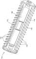
FIG. 5 is a perspective view of the head of the hair modification appliance shown in FIGS. 1 and 2;
FIG. 6 is a bottom view of the blade assembly of the head shown in FIG. 5;
FIG. 7 is a top plan view of the stationary blade of the blade assembly shown in FIG. 6;
FIG. 8 is a side view of the stationary blade shown in FIG. 7;
FIG. 9 is a schematic cross-sectional view of a portion of the blade assembly shown in FIG. 6;
FIG. 10 is a top plan view of the movable blade of the blade assembly shown in FIG. 6;
FIG. 11 is a perspective view of the guard of the head shown in FIG. 5;
FIG. 12 is an enlarged cross-sectional view of a portion of the head shown in FIG. 5, including the blade assembly of FIG. 6 and the guard of FIG. 11;
FIG. 13 is an enlarged bottom view of a portion of the head of FIG. 5;
FIG. 14 is a perspective view of a second embodiment of a hair grooming appliance;
FIG. 15 is an enlarged perspective view of a portion of the hair modification appliance shown in FIG. 14;
FIG. 16 is a top plan view of the head of the hair grooming appliance shown in FIG. 14;
FIG. 17 is a bottom view of the stationary blade of the hair modification appliance shown in FIG. 14;
FIG. 18 is a top plan view of the movable blade of the hair grooming appliance shown in FIG. 14;
fig. 19 is a side view of the fixed blade and the movable blade of the hair grooming appliance shown in fig. 14;
FIG. 20 is a cross-sectional view of the head of the hair modification appliance shown in FIG. 14;
FIG. 21 is a perspective view of an embodiment of a head for use with the hair modification appliance shown in FIGS. 1 and 14;
FIG. 22 is a side view of a blade assembly of the head shown in FIG. 21;
FIG. 23 is a top plan view of the stationary blade of the blade assembly shown in FIG. 22.
Corresponding reference characters indicate corresponding parts throughout the drawings.
Unless otherwise indicated, the drawings provided herein are intended to illustrate features of embodiments of the present disclosure. These features are believed to be applicable in a variety of systems including one or more embodiments of the present disclosure. As such, the drawings are not meant to include all of the conventional features known to those of ordinary skill in the art to be required to practice the embodiments disclosed herein.
Detailed Description
In the following specification and claims, reference will be made to a number of terms which shall be defined to have the following meanings. The singular forms "a", "an" and "the" include plural referents unless the context clearly dictates otherwise. The terms "comprising," "including," and "having" are intended to be inclusive and mean that there may be additional elements other than the listed elements. "optional" or "optionally" means that the subsequently described event or circumstance may or may not occur, and that the description includes instances where the event occurs and instances where it does not.
Approximating language, as used herein throughout the specification and claims, may be applied to modify any quantifiable representation that may vary permissibly without resulting in a change in the basic function to which it is related. Accordingly, a value modified by a term or terms, such as "about", "about" and "substantially", are not to be limited to the precise value specified. In at least some instances, the approximating language may correspond to the precision of an instrument for measuring the value. Here and throughout the specification and claims, range limitations may be combined and/or interchanged; unless context or language indicates otherwise, such ranges are identified and include all sub-ranges subsumed therein.
Referring now to the drawings, and in particular to fig. 1 and 2, a hand-held hair grooming tool in accordance with one embodiment is shown in the form of an electric hand-held hair trimmer, generally designated 100. However, it is contemplated that the embodiments described herein may be used on other hand-held hair grooming appliances, such as electric shavers and hair clippers. The trimmer 100 includes a handle, generally indicated at 102, and a head, generally indicated at 104, mounted on and supported by the handle (broadly, a hair grooming assembly). The handle 102 and head 104 together generally definebase:Sub>A longitudinal axisbase:Sub>A-base:Sub>A of the trimmer 100. A suitable motor (not shown) is provided in the handle 102 along with a drive assembly 106 (shown in fig. 4). The drive motor may be powered by one or more batteries (not shown) disposed within the handle 102 and/or by another suitable internal or external power source. In the illustrated embodiment, the head 104 is separable from the handle 102. Thus, the head 104 may be removed and another head 104 may be positioned on the handle 102. However, in other embodiments, the head 104 may be secured to the handle 102 without departing from the scope of the present invention.
Referring to fig. 3-6, head 104 includes a blade assembly 108 operatively connected to a motor through drive assembly 106, a blade guard 110, and a mounting pin 112. The mounting arms project outwardly from the handle, with the head 104 extending laterally between the arms. Mounting pins 112 extend through the respective mounting arms and blade guard 110 to pivotally mount the head 104 on the handle 102. Thus, the head 104 may pivot about a pivot axis extending through the mounting pin 112. In other embodiments, the position of the head 104 may be fixed (i.e., non-pivotable) relative to the handle 102. In some embodiments, the head 104 may be switchable between a pivotable configuration and a non-pivotable configuration. In still other embodiments, the head 104 may pivot about more than one pivot axis.
Referring to fig. 7 and 8, the stationary blade 114 is suitably a dual-blade assembly including a first lateral edge 118, a second lateral edge 120, and an intermediate portion 122. The first transverse edge portion 118 includes a set of blade teeth 124 that define a first edge 126 of the blade 114. The second transverse blade portion 120 includes an opposing set of blade teeth 124 that define a second edge 130 of the blade 114. In other embodiments, blade assembly 108 may be a single-edge blade assembly or any other suitable blade assembly that enables trimmer 100 to operate as described herein.
The illustrated first and second edges 126, 130 are straight. In other embodiments, the first edge 126 and/or the second edge 130 may be at least partially curved or angled.
In the illustrated embodiment, the intermediate portion 122 is disposed between the first and second lateral blade portions 118, 120 and spans between the first and second lateral blade portions 118, 120 and includes a planar upper surface 132. In other embodiments, intermediate portion 122 may include, but is not limited to, an apex, a curved surface, an angled surface, and any other suitable portion. For example, in some embodiments, the intermediate portion 122 may include an apex connecting the first and second transverse blade portions 118, 120.
The first lateral edge portion 118 includes a first upper surface 134 that extends from the first edge 126 to the upper surface 132 of the intermediate portion 122. The second transverse edge portion 120 includes a second upper surface 136 that extends from the second edge 130 to the upper surface 132 of the intermediate portion 122. The first and second upper surfaces 134, 136 may include at least one of an angled surface, a concave curve, and a convex curve extending along at least a portion of the respective upper surface 134, 136 between the intermediate portion 122 and the respective edge 126, 130. In the illustrated embodiment, the first and second upper surfaces 134, 136 are angled. Thus, the double angle creates the appearance of a double-beveled edge on opposite sides of the intermediate portion 122. As used herein, the terms "bevel" and "incline" refer to a surface that is inclined to an adjacent surface.
Because the fixed blade 114 is beveled from the upper surface 132 to the respective edges 126, 130, it is believed that such beveling of the fixed blade 114 provides a sharper, more durable blade than conventional blades that are generally flat or planar. For example, the illustrated bevel of the fixed blade 114 allows the first and second lateral edges 118, 120 to reach a relatively sharp point where the blade is thinner, i.e., sharper, at the first and second edges 126, 130 than conventional blades. Additionally, the bevels allow the thickness of the stationary blade 114 to vary at a constant rate as the blade extends from the intermediate portion 122 to the respective edges 126, 130. Further, the angled angle allows the blade 114 to have an increased thickness in the intermediate portion 122, which reduces warping of the blade 114. In contrast, at least some known blades include multiple surfaces having different slopes. In such known blades, there may be regions of high stress in the portions of the blade where the slope changes. Such conventional blades may also include a thin and plate-like section. As a result, such blades may deteriorate and even break after repeated use. In contrast, the stationary blade 114 of the illustrated embodiment has a sharper point and increased durability due to the bevel.
The illustrated stationary blade 114 has a laterally extending length 137 (FIG. 7). In some embodiments, the length 137 is in the range of about 5mm to about 50mm, depending on the intended use of the trimmer 100, and more preferably in the range of about 10mm to about 40 mm. In the illustrated embodiment, the length 137 is approximately 39mm. In other embodiments, the stationary blade 114 may have another suitable length and still fall within the scope of the present invention.
Referring now to fig. 9, the fixed blade 114 and the movable blade 116 are in shearing contact with one another to define a cutting plane 138 therebetween. Specifically, the movable blade 116 is configured to contact a lower surface 140 (shown in fig. 8) of the respective first and second lateral edge portions 118, 120 along the cutting plane 138 as the movable blade reciprocates. The upper surface 132 of the intermediate portion 122 is substantially parallel to the cutting plane 138. The first and second upper surfaces 134, 136 (shown in fig. 8) are angled relative to the cutting plane 138.
In the illustrated embodiment, the stationary blade 114 is symmetrical about the midline of the middle portion 122. Accordingly, the second transverse edge 120 is substantially equal in size to the first transverse edge 118. Thus, the description herein (including the dimensions) of the first transverse edge 118 may also apply to the second transverse edge 120, and vice versa. In other embodiments, the second transverse edge 120 and the first transverse edge 118 may be different and still be within the scope of the present invention.
As shown in fig. 9, the first upper surface 134 extends continuously from the upper surface 132 of the intermediate portion 122 to the first edge 126 at a constant slope. The first upper surface 134 thus defines an angle 142 with the cutting plane 138. In some embodiments, the angle 142 is suitably in the range of about 5 ° to about 25 °, and more preferably in the range of about 10 ° to about 20 °. In the illustrated embodiment, the angle 142 is about 15 °.
The first lateral blade portion 118 also has a width 143 (fig. 8) extending from the first edge 126 to the intermediate portion 122. In suitable embodiments, the width 143 is in the range of about 0.5mm to about 10mm, more preferably in the range of about 2mm to about 6mm, and even more preferably in the range of about 4mm to about 5mm. In the illustrated embodiment, the width 143 of the first lateral blade portion 118 is about 4.5mm.
The first transverse blade portion 118 also has a generally flat lower surface 140 opposite the first upper surface 134. The lower surface 140 is substantially parallel to the upper surface 132 of the intermediate portion 122 and the cutting plane 138. The first upper surface 134 extends at a constant angle relative to the lower surface 140 from the first edge 126 to the intermediate portion 122. Accordingly, referring to FIG. 9, the first transverse blade portion 118 has a varying thickness 144 between the first upper surface 134 and the lower surface 140. The first transverse edge portion 118 has a minimum thickness 144 at the first edge 126. In some embodiments, the thickness 144 at the first edge 126 is in a range of about 0.02 millimeters (mm) to about 0.07 mm. In the illustrated embodiment, the thickness 144 at the first edge 126 is about 0.06mm.
Referring back to FIG. 7, each of the first and second transverse blade portions 118, 120 includes a respective set of teeth 124 that at least partially form respective first and second edges 126, 130. Each tooth 124 has a width 146 at the respective edge 126, 130. In some embodiments, the width 146 is in the range of about 0.2mm to about 1mm, and more preferably in the range of about 0.3mm to about 0.6 mm. In the illustrated embodiment, the width 146 is about 0.5mm. The teeth 124 are equally spaced from one another by respective gaps 148 therebetween. The gaps 148 each have a width 152 at the respective edge 126, 130. In some embodiments, the width 152 of each gap is in the range of about 0.1mm to about 0.5mm. In the illustrated embodiment, the width 152 is about 0.3mm.
Referring to FIG. 9, in one suitable embodiment, the stationary blade 114 may be formed from a sheet of material and the material removed to form the gap 148, thereby also defining the teeth 124. For example, a tool (not shown) may be used to remove material between the teeth 124 according to a predetermined tool depth 155. In some embodiments, the tool depth 155 is in a range from about 0.5mm to about 2 mm. In the illustrated embodiment, the tool depth 155 is about 1mm. At the tool depth 155, a grooved surface 156 is formed between the teeth 124. These groove surfaces 156 are inclined at an angle 158 (fig. 9) relative to the cutting plane 138 from the lower surface 140 to the respective angled upper surfaces 134, 136. In some embodiments, the angle 158 of each groove surface 156 is in the range of 15 ° to about 45 °. In the illustrated embodiment, the angle 158 is about 30 °. It should be appreciated that, in other embodiments, the teeth 123 of the stationary blade 114 may be formed in other suitable manners and/or have other suitable configurations without departing from the scope of the present invention.
As best shown in FIG. 8, the stationary blade 114 is configured to further have a cavity 150 in a lower surface opposite the upper surface 132 of the blade's middle portion 122. The cavity 150 spans the intermediate portion and further extends into the first and second lateral blade portions 118, 120. The cavity 150 is configured to receive a mounting component for connecting the stationary blade 114 to the head 104. For example, in the illustrated embodiment, the post 151 extends through the movable blade 116 and connects to the middle portion 122 of the fixed blade 114. The post 151 may be connected to the stationary blade 114 in any suitable manner. For example, the post 151 may be welded to the stationary blade 114. In the illustrated embodiment, post 151 is integrally formed with guard 110 and retains blade assembly 108 within the guard. In other embodiments, the components of the head 104 may be connected to each other in any manner that enables the trimmer 100 to operate as described.
Referring to FIG. 9, the stationary blade 114 may have a reduced thickness along the cavity 150. For example, in the illustrated embodiment, the thickness 154 of the intermediate portion 122 above the cavity 150 is less than the distance 153 between the upper surface 132 and the cutting plane 138. The depth of cavity 150 is the difference between distance 153 and thickness 154. In some embodiments, distance 153 is in the range of about 0.5mm to about 2mm, more preferably in the range of about 1mm to about 1.5 mm. In some embodiments, the thickness 154 is in the range of about 0.25mm to about 1.25mm, and more preferably in the range of about 0.5mm to about 1mm. In other embodiments, the stationary blade 114 may have any suitable thickness. In alternative embodiments, the cavity 150 may be omitted.
Referring now to fig. 10, the movable blade 116 includes a first lateral edge portion 160, a second lateral edge portion 162, and an intermediate portion 164. The intermediate portion 164 extends between the first and second lateral edge portions 160, 162 and is substantially planar. The first and second lateral blades 160, 162 extend at an angle relative to the cutting plane 138. Each of the first and second lateral blades 160, 162 includes teeth 166. In other embodiments, the movable blade 116 may have a different configuration and be within the scope of the present invention.
The movable blade 116 has a thickness defined between opposing surfaces of the movable blade. The thickness may be in the range of about 0.05mm to about 0.60 mm. The thickness may vary throughout the movable blade 116. For example, the movable blade 116 may have a maximum thickness in the middle portion 164 and a minimum thickness in the teeth 166. In other embodiments, the movable blade 116 may have a different thickness and be within the scope of the present invention.
Referring to fig. 4 and 11-13, guard 110 is generally V-shaped in cross-section, generally defining an interior space in which blade assembly 108 is disposed when head 104 is assembled. The guard generally includes a middle portion 168 and lateral combs 170, the lateral combs 170 being disposed on opposite sides of the middle portion and generally corresponding to the first and second lateral blades 118, 120 of the stationary blades 114. Each comb 170 includes a respective set of comb teeth 172 that correspond to and are proximate to the respective teeth 124 of the fixed blade 114 and the associated teeth 166 of the movable blade 116. In other embodiments, the guard 110 may have other suitable configurations without departing from the scope of the present disclosure.
As shown in fig. 13, the width 174 of each comb tooth 172 of the guard 110 is greater than the width 146 of the fixed blade teeth 124 and the width of the movable blade teeth 166. In some suitable embodiments, the width 174 is in the range of about 0.2mm to about 1.2mm, and more preferably in the range of about 0.5mm to about 0.8 mm. The comb teeth 172 of the guard 110 are equally spaced from each other by suitable gaps 176. In some embodiments, the width 177 of the gap 176 is in the range of about 1mm to about 2mm, more preferably in the range of about 1.25mm to about 1.75 mm. In the illustrated embodiment, the guard 110 is configured such that the guard's comb teeth 172 are aligned with approximately every other tooth 166 of the movable blade 116. The relatively greater spacing of the comb teeth 172 of the guard 110 allows the stationary blade 114 and the movable blade 116 to cut a greater range of hair lengths. In particular, the arrangement of the comb teeth 172 enables long hairs to enter between the teeth 172 and be cut by the blade assembly 108.
With particular reference to fig. 12, since guard 110 is generally V-shaped in cross-section, the comb 170 of the guard extends upwardly and outwardly at an angle 178 relative to the cutting plane 138 of blade assembly 108 beyond the edges 126, 130 of the stationary blade. In some embodiments, the angle 178 of the comb 170 of the guard 110 is in the range of about 5 ° to about 85 °, and more suitably in the range of about 20 ° to about 45 °. In the illustrated embodiment, the angle 178 is approximately 30 °.
In addition, since the comb 170 of the guard 110 is angled in this manner, the comb is spaced from the respective edge 126, 130 of the stationary blade 114, e.g., to define a respective space 128 extending perpendicular to and from the comb to the respective edge 126, 130 of the stationary blade. In some embodiments, the width of the space 128 is in the range of about 0.1mm to about 0.5mm. In this manner, the guard 110 is configured to increase the comfort of the person being trimmed of hair. For example, the disclosed configuration of guard 110 reduces pinching of the user's skin during trimming, e.g., when moving the trimmer across the user's face during trimming. The configuration of the guard 110 also reduces skin irritation that would otherwise be caused by the blades 114, 116 directly contacting the skin. However, it should be understood that in other embodiments, the guard 110 may be configured differently than illustrated and described herein and still be within certain aspects of the present invention.
The guard 110 extends at least to the cutting plane 138. Specifically, in the illustrated embodiment, the comb 170 of the guard 110 extends from the middle portion 168 of the guard 110 to near the base of the stationary blade 114 beyond the cutting plane 138. At least some of the comb teeth 171 extend beyond the cutting plane 138 to accommodate flexing of the blades 114, 116, for example, in the middle of the blades. The comb teeth 171 located near the ends of the blades 114, 116 may extend to and terminate at the cutting plane 138. In other embodiments, the comb 170 of the guard 110 may extend any distance that enables the guard 110 to function as described.
In some embodiments, at least some of the comb teeth 171 have a thickness and/or height that is different from the thickness and/or height of other comb teeth. For example, in some embodiments, the comb teeth 171 extending near the ends of the blades 114, 116 are thinner and shorter than the comb teeth 171 extending near the middle of the blades 114, 116. Accordingly, the larger comb teeth 171 can accommodate any flexing of the middle of the blades 114, 116 during operation. In addition, the increased size of the comb teeth 171 provides increased comfort and further reduces the risk of skin being pinched between the blades 114, 116 or coming into contact with the blades 114, 116 at the cutting plane 138. In addition, the varying thickness and height of the comb teeth 171 are configured to maintain a reduced visual profile of the guard 110. In some embodiments, the guard 110 may include at least one comb tooth 171 having a thickness of at least about 0.5mm or at least about 1.5mm or at least about 5mm. In some embodiments, the guard 110 may include at least one comb 171 having a thickness of no more than about 0.1mm. In other embodiments, comb teeth 171 may have any thickness that enables guard 110 to function as described herein.
Referring now to fig. 14-20, a second embodiment of an electric hair grooming appliance is also shown generally at 200 (fig. 14) in the form of a trimmer. More specifically, the illustrated trimmer 200 is similar to the trimmer 100 of the embodiment of fig. 1-13 in that it includes a handle, generally indicated at 202, and a head, generally indicated at 204, mounted on the handle (broadly, a hair grooming assembly). The handle 202 and head 204 together generally define a longitudinal axis B-B of the trimmer 200. In this embodiment, the head 204 is fixed, e.g., non-pivotable, relative to the handle 202. The head 204 may be suitably removed from the handle 202 for cleaning and/or replacement. However, it should be understood that in other embodiments, the head 104 may be attached to the handle 102.
Referring to fig. 15-17, the head 204 includes a blade assembly 208 and a guard 210, the guard 210 configured to receive the blade assembly therein. The blade assembly 208 generally includes a fixed blade 214 and a movable blade 216. The fixed blade 214 includes a first lateral blade 218, a second lateral blade 220, and an intermediate portion 222, the intermediate portion 222 extending between the first and second lateral blades 218, 220 and including a substantially planar upper surface 232. The first lateral blade portion 218 includes blade teeth 224 defining a first edge 226 of the stationary blade 214. The second lateral blade portion 220 includes blade teeth 224 that form a second edge 230 of the fixed blade 214. The first transverse edge portion 218 includes a first upper surface 234 extending from the first edge 226 to the upper surface 232, while the second transverse edge portion 220 includes a second upper surface 236 extending from the second edge 230 to the upper surface 232. The first and second upper surfaces 234, 236 extend continuously from the respective edges 226, 230 to the upper surface 232 at a constant slope such that the stationary blade is inclined on both lateral sides of the middle portion 222. The stationary blade 214 of the present embodiment suitably has a length 237 of about 12 mm. However, in other embodiments, the length of the stationary blade 214 may be greater than or less than 12mm and still be within the scope of the present invention.
As shown in fig. 18, the movable blade 216 includes a first lateral edge portion 260, a second lateral edge portion 262, and an intermediate portion 264 extending therebetween. The intermediate portion 264 extends between the first and second transverse blade portions 260, 262 and is substantially planar. Additionally, intermediate portion 264 is substantially parallel to cutting plane 238 defined by the interface between fixed blade 214 and movable blade 216. The first and second transverse blades 260, 262 are angled with respect to the cutting plane 238. Each of the first and second lateral edge portions 260, 262 includes a set of blade teeth 266. In other embodiments, the movable blade 216 may have a different configuration without departing from certain aspects of the present invention.
Referring now to fig. 19, the movable blade 216 is configured to contact the lower surfaces 240 of the first and second lateral blade portions 218, 220 of the fixed blade 214 as the movable blade reciprocates. The upper surface 232 of the middle portion of the stationary blade 214 is substantially parallel to the cutting plane 238. In contrast, the first and second upper surfaces 234, 236 of the stationary blade are angled relative to the cutting plane 238 and thus relative to the upper surface 232 of the middle portion 222. The lower surface 240 of the stationary blade is opposite the respective first and second upper surfaces 234, 236 of the stationary blade. The lower surface 240 is substantially planar and parallel to the upper surface 232 and the cutting plane 238.
In the illustrated embodiment, the stationary blade 214 is symmetrical about the midline of the middle portion 222. Accordingly, the second transverse edge 220 is substantially equal in size to the first transverse edge 218. Thus, the description of the first lateral edge 218 (including dimensions) may also apply to the second lateral edge 220, and vice versa. In other embodiments, the second transverse blade 220 and the first transverse blade 218 may have different sizes. The first upper surface 234 defines an angle 242 with the cutting plane 238 in the range of about 5 ° to about 25 °, and more preferably in the range of about 10 ° to about 20 °. In the illustrated embodiment, angle 242 is approximately 15 °.
The first lateral edge portion 218 extends at a constant angle from the first edge 226 away from the lower surface 240 to the intermediate portion 222. Accordingly, the first transverse blade portion 218 has a varying thickness 244 between the first upper surface 234 and the lower surface 240. The first transverse edge portion 218 has a minimum thickness 244 at the first edge 226 in a range of about 0.02 millimeters (mm) to about 0.07 mm. In the illustrated embodiment, the thickness 244 at the first edge 226 is about 0.06mm.
Referring back to FIG. 17, each of the first and second transverse blade portions 218, 220 includes a respective blade tooth 224 that at least partially forms an edge 226, 230. The width 250 of each tooth at the respective edge 226, 230 is in the range of about 0.2mm to about 1mm, more preferably in the range of about 0.3mm to about 0.6 mm. In the illustrated embodiment, the width 250 of each blade tooth 224 is about 0.5mm. The teeth 124 are spaced apart by suitable gaps 248, the gaps 248 having a width 252 at the respective edges 226, 230 in the range of about 0.1mm to about 0.5mm. In the illustrated embodiment, the width 252 is about 0.3mm.
Referring to fig. 20, the guard 210 is generally V-shaped in cross-section and includes a middle portion 268 and opposing combs 270 extending outwardly and upwardly from the middle portion to form an interior space for receiving the blade assembly 208 therein. The guard 210 is configured to receive the blade assembly 208 such that the comb 270 extends adjacent to but outside of the edges 226, 230 of the stationary blade 214. In particular, comb 270 includes comb teeth 272 that extend adjacent to fixed blade teeth 224 and movable blade teeth 266. In other embodiments, the guard 210 may have other configurations without departing from certain aspects of the present disclosure.
As shown in fig. 16, the width 274 of each comb tooth 272 is greater than the respective widths of the fixed blade teeth 224 and the movable blade teeth 266. In some embodiments, the width 274 of each comb tooth is in the range of about 0.5mm to 1mm, more preferably in the range of about 0.6mm to about 0.8 mm. The teeth are suitably spaced from one another by gaps 276, each gap 276 having a gap width 277 in the range of about 1mm to about 2mm, more preferably in the range of about 1.5mm to about 1.8 mm. In the illustrated embodiment, the comb teeth 272 and the gap width 277 enable two fixed blade teeth 224 to be positioned between each pair of adjacent comb teeth 272.
Referring to fig. 20, comb 270 extends through blade assembly 208 at an angle 278 relative to cutting plane 238. In some embodiments, the angle 278 is in the range of about 5 ° to about 85 °, more preferably in the range of about 20 ° to about 45 °. The comb portion 270 is spaced from the respective edges 226, 230 of the stationary blade 214 to define a space 228 therebetween on opposite sides of the stationary blade 214, as determined perpendicular to the comb and extending from the comb to the respective edges of the stationary blade 214. In some embodiments, the width of each space 228 is in the range of about 0.1mm to about 0.5mm.
Referring now to fig. 21-23, one embodiment of a head for use with hair grooming appliance 100 (shown in fig. 1) and hair grooming appliance 200 (shown in fig. 2) is generally indicated at 300 (fig. 21). The head 300 includes a blade assembly 302 and a guard 304 configured to receive the blade assembly therein. The blade assembly 302 generally includes a fixed blade 306 and a movable blade 308 (fig. 22). The head 300 may have other configurations without departing from certain aspects of the present invention.
Referring to fig. 23, the stationary blade 306 includes a first lateral edge 310, a second lateral edge 312, and an intermediate portion 314, the intermediate portion 314 extending between the first and second lateral edges 310, 312 and including a substantially planar upper surface 316. The first lateral blade portion 310 includes blade teeth 318 that form a first edge 320 of the fixed blade 306. The second lateral blade portion 312 includes blade teeth 322 that form a second edge 324 of the fixed blade 306. The stationary blade 306 of the present embodiment suitably has a lateral extension 334 of about 39mm. However, in other embodiments, the length of the stationary blade 306 may be greater than or less than 39mm and remain within the scope of the present invention.
The first transverse blade portion 310 includes a first upper surface 326 and a first curved upper surface 328. The first upper surface 326 extends from the planar upper surface 316 to a first curved upper surface 328. The first curved upper surface 328 extends from the first upper surface 326 to the first edge 320.
The second transverse blade portion 312 includes a second upper surface 330 and a second curved upper surface 332. Second upper surface 330 extends from upper surface 316 to second curved upper surface 332. A second curved upper surface 332 extends the second edge 324 from the second upper surface 330.
As shown in fig. 22, the first and second curved upper surfaces 328, 332 are concave and curved toward the flat lower surface 337 of the stationary blade 306. Accordingly, the stationary blade 306 has a reduced thickness along the first and second curved upper surfaces 328, 332. In particular, the stationary blade 306 has a minimum thickness 336 defined between each curved upper surface 328, 332 and a respective planar lower surface 337 of the stationary blade 306. The planar lower surface 337 is configured to contact the movable blade 308. In some embodiments, the minimum thickness 336 is in a range of about 0.05mm to about 0.1mm. In this embodiment, the minimum thickness 336 is about 0.08mm.
First curved upper surface 328 and second curved upper surface 332 each have a radius 338. Each radius 338 may be any suitable radius that enables stationary blades to function as described herein.
In some embodiments, the trimmer includes a handle, a drive assembly in the handle, and a head attached to the handle. The head includes a fixed blade including a first lateral blade, a second lateral blade, and an intermediate portion connecting the first and second lateral blades. The first transverse edge portion includes blade teeth defining a first edge of the blade. The second transverse edge portion includes blade teeth defining a second edge of the blade. The first lateral edge portion further includes a first upper surface extending from the first edge to the intermediate portion, and the second lateral edge portion further includes a second upper surface extending from the second edge to the upper surface of the intermediate portion. The first upper surface includes at least one of an angled surface, a concave surface, and a convex surface along at least a portion of an extension of the first upper surface between the intermediate portion and the first edge. The head further includes a movable blade in shearing contact with the first and second lateral edges of the fixed blade. The drive assembly is configured to reciprocate the movable blade relative to the fixed blade.
In one such embodiment, the second upper surface includes at least one of an angled surface, a concave surface, and a convex surface along at least a portion of an extension of the second upper surface between the intermediate portion and the first edge.
In another such embodiment, the middle portion includes a substantially planar upper surface extending between the first and second upper surfaces.
In yet another such embodiment, the fixed blade and the movable blade contact each other to define a cutting plane that is substantially planar and parallel to an upper surface of the middle portion of the fixed blade.
In another such embodiment, the first upper surface is angled relative to the cutting plane.
In yet another such embodiment, the angle between the first upper surface and the cutting plane is in the range of about 5 ° to about 25 °.
In another such embodiment, the angle between the first upper surface and the cutting plane is in the range of about 10 ° to about 20 °.
In yet another such embodiment, the fixed blade has a thickness at the first edge in a range of about 0.02 millimeters (mm) to about 0.07 mm.
In yet another such embodiment, the fixed blade has a thickness at the first edge of about 0.06mm.
In yet another such embodiment, the first upper surface includes a curve extending along a portion of the extension of the first upper surface between the intermediate portion and the first edge.
In yet another such embodiment, the second upper surface includes a curve extending along a portion of the extension of the second upper surface between the intermediate portion and the second edge.
In yet another such embodiment, the stationary blade has a minimum thickness defined by the first upper surface, the minimum thickness being in a range of about 0.05mm to about 0.1mm.
In yet another such embodiment, the tip thickness of the stationary blade is in a range of about 0.1mm to about 0.5mm.
In yet another such embodiment, the first upper surface includes a concave curve.
In other embodiments, the trimmer includes a handle, a drive assembly in the handle, and a blade assembly configured to be operatively connected to the drive assembly. The blade assembly includes a stationary blade having blade teeth. Each blade tooth has a width. The blade assembly also includes a movable blade having blade teeth. The drive assembly is operable to reciprocate the movable blade relative to the fixed blade. The blade assembly further comprises a guard disposed outside and extending adjacent respective blade teeth of the fixed blade and the movable blade. The guard includes comb teeth. The width of each comb tooth is larger than that of each fixed blade tooth.
In one such embodiment, the fixed blade and the movable blade together define a cutting plane. The guard extends at least to the cutting plane.
In another such embodiment, a gap in the range of about 0.1mm to about 0.5mm is defined between the guard and the stationary blade at the cutting plane.
In yet another such embodiment, the blade assembly is pivotally connected to the handle.
In yet another such embodiment, each blade tooth of the stationary blade has a width in a range of about 0.2mm to about 1mm.
In yet another such embodiment, the blade teeth of the stationary blade are spaced apart by a gap having a width in the range of about 0.2mm to about 0.5mm.
In yet another such embodiment, the width of each comb tooth is in the range of about 0.5mm to about 1.2 mm.
In yet another such embodiment, the comb teeth of the guard are spaced apart by a gap. The width of each gap is in the range of about 1mm to about 2 mm.
In other embodiments, a hair modification appliance includes a handle, a drive assembly in the handle, and a head attached to the handle. The head includes a blade assembly including a fixed blade and a movable blade. The drive assembly is operable to reciprocate the movable blade relative to the fixed blade. Each of the fixed and movable blades includes respective blade teeth. The blade teeth of the fixed blade define first and second edges of the fixed blade. The fixed blade includes a first lateral blade, a second lateral blade, and an intermediate portion extending therebetween. The first lateral edge has a first upper surface extending from the first edge of the stationary blade to an intermediate portion. The second lateral blade portion includes a second upper surface extending from the second edge of the fixed blade to the intermediate portion. The first upper surface includes at least one of an angled surface, a concave surface, and a convex surface along at least a portion of an extension of the first upper surface between the intermediate portion and the first edge. The second upper surface includes at least one of an angled surface, a concave surface, and a convex surface of at least a portion of an extension of the second upper surface between the intermediate portion and the second edge. The head further includes a guard configured to receive the blade assembly therein and having opposed combs disposed proximate the first and second edges of the stationary blade. Each comb has teeth.
In one such embodiment, the fixed blade and the movable blade define a cutting plane therebetween. The angle between the first upper surface and the cutting plane is in the range of about 5 ° to about 25 °.
In another such embodiment, the blade teeth of the stationary blade each have a width. The width of each comb tooth is greater than the width of each blade tooth of the fixed blade.
In yet another such embodiment, the comb of the guard is spaced from the first and second edges of the stationary blade in a range of about 0.1mm to about 0.5mm determined perpendicular to the respective comb.
In yet another such embodiment, the head is pivotally attached to the handle.
As noted above, embodiments of the trimmer include a blade that includes at least one beveled edge. In some embodiments, the blade is a double-edged blade and comprises two beveled edges. The beveled edge makes the blade sharper than conventional blades while also being more durable than at least some known blades. Thus, the blade may have a longer service life. Moreover, in some embodiments, the assembly cost of the trimmer may be lower than the assembly cost of at least some known trimmers.
Additionally, embodiments of the trimmer include a blade that includes a curved or concave surface along the beveled edge. The curved surface allows the blade to be thinned near the cutting edge of the movable blade to provide a tighter cut. In addition, the blade includes a relatively thick portion that resists flexing of the blade. Also, in some embodiments, the curved surface is concave and allows the blade to have a thicker tip.
In addition, embodiments of the trimmer include a guard having comb teeth closely spaced from the blade assembly. The guard protects the person's skin as the trimmer moves along the skin. In addition, the guard allows the blade assembly to cut a greater range of hair.
Exemplary embodiments of devices, systems, and methods for hair grooming appliances are described above in detail. The apparatus, systems, and methods described herein are not limited to the specific embodiments described, but rather, components of the apparatus, systems, and/or steps of the method may be utilized independently and separately from other components and/or steps described herein. For example, these methods may also be used in combination with other hair modification appliances, systems, and methods, and are not limited to practice with only the devices, systems, and methods as described herein. Rather, the exemplary embodiment can be implemented and utilized in connection with many other modification applications.
Although specific features of various embodiments of the invention may be shown in some drawings and not in others, this is for convenience only. In accordance with the principles of the invention, any feature of a drawing may be discussed and/or claimed in combination with any feature of any other drawing.
This written description uses examples to disclose the embodiments, including the best mode, and also to enable any person skilled in the art to practice the embodiments, including making and using any devices or systems and performing any incorporated methods. The patentable scope of the disclosure is defined by the claims, and may include other examples that occur to those skilled in the art. Such other examples are intended to be within the scope of the claims if they do not differ from the structural elements described in the literal language of the claims, or if they include equivalent structural elements with insubstantial differences from the literal languages of the claims.
As various changes could be made in the above embodiments without departing from the scope of the disclosure, it is intended that all matter contained in the above description and shown in the accompanying drawings shall be interpreted as illustrative and not in a limiting sense.
Claims (15)
1. An electrically powered hand-held hair grooming appliance comprising:
a handle;
a drive assembly in the handle; and
a head attached to the handle and comprising:
a stationary blade, comprising:
a first transverse blade having a first upper surface and blade teeth defining a first edge of the fixed blade;
a second transverse blade having a second upper surface and blade teeth defining a second edge of the fixed blade; and
a middle portion connecting the first and second lateral edges, the first upper surface extending from the first edge to the middle portion, the second upper surface extending from the second edge to the middle portion, the first and second lateral edges being inclined from the middle portion to respective edges of the stationary blade, wherein the stationary blade is symmetrical about a midline of the middle portion; and
a movable blade in shearing contact with the first and second lateral edges of the fixed blade, wherein the drive assembly is operable to reciprocate the movable blade relative to the fixed blade.
2. The powered hand-held hair grooming appliance in accordance with claim 1, wherein the first upper surface comprises at least one of an angled surface, a concave surface and a convex surface along at least a portion of the extension of the first upper surface between the middle portion and the first edge.
3. The powered hand-held hair grooming appliance in accordance with claim 2, wherein the second upper surface comprises at least one of an angled surface, a concave surface, and a convex surface along at least a portion of the extension of the second upper surface between the intermediate portion and the second edge.
4. The powered hand-held hair grooming appliance in accordance with claim 1, wherein the intermediate portion comprises a substantially planar upper surface extending between the first and second upper surfaces.
5. The powered hand-held hair grooming appliance in accordance with claim 4, wherein the stationary blade and the movable blade contact each other to define a cutting plane that is substantially planar and parallel to the upper surface of the middle portion of the stationary blade.
6. The powered hand-held hair modification appliance of claim 5, wherein the first upper surface is angled relative to the cutting plane, the angle between the first upper surface and the cutting plane being in the range of about 5 ° to about 25 °.
7. The powered hand-held hair modification appliance of claim 6, wherein the angle between the first upper surface and the cutting plane is in the range of about 10 ° to about 20 °.
8. The powered hand-held hair modification appliance of claim 1, wherein a thickness of said stationary blade at said first edge is in the range of about 0.02mm to about 0.07 mm.
9. The powered hand-held hair grooming appliance in accordance with claim 8, wherein the thickness of the stationary blade at the first edge is about 0.06mm.
10. The electric hand-held hair grooming appliance in accordance with claim 1, wherein the head further comprises a mounting member extending through the movable blade and connected to an intermediate portion of the stationary blade.
11. A blade assembly for a powered hand-held hair grooming appliance, the blade assembly comprising:
a stationary blade, comprising:
a first transverse blade having a first upper surface and blade teeth defining a first edge of the fixed blade;
a second transverse blade having a second upper surface and blade teeth defining a second edge of the fixed blade; and
an intermediate portion connecting the first and second lateral edges, the first upper surface extending from the first edge to the intermediate portion, the second upper surface extending from the second edge to the intermediate portion, the first and second lateral edges sloping from the intermediate portion to respective edges of the fixed blade, wherein the fixed blade is symmetrical about a midline of the intermediate portion; and
a movable blade in shearing contact with the first and second lateral edges of the fixed blade; and
a mounting member connected to an intermediate portion of the fixed blade, wherein the mounting member extends through the movable blade.
12. The blade assembly of claim 11, wherein the middle portion comprises a substantially planar upper surface extending between the first and second upper surfaces.
13. The blade assembly according to claim 12, wherein said fixed blade and said movable blade are in contact with each other to define a cutting plane, said cutting plane being substantially planar and parallel to an upper surface of a middle portion of said fixed blade.
14. The blade assembly of claim 13, wherein the first upper surface is angled relative to the cutting plane.
15. A head for an electric hand-held hair trimmer, the head comprising:
a stationary blade, comprising:
a first transverse blade having a first upper surface and blade teeth defining a first edge of the fixed blade;
a second transverse blade having a second upper surface and blade teeth defining a second edge of the fixed blade; and
an intermediate portion connecting the first and second lateral edge portions, the first upper surface extending from the first edge to the intermediate portion, the second upper surface extending from the second edge to the intermediate portion, wherein the first upper surface comprises at least one of an angled surface, a concave surface, and a convex surface along at least a portion of an extension of the first upper surface between the intermediate portion and the first edge;
a movable blade comprising a first edge and an opposing second edge, the first and second edges comprising blade teeth in shearing contact with corresponding blade teeth of the fixed blade; and
a guard disposed outside and extending adjacent respective blade teeth of the stationary blade and the movable blade, wherein the guard defines an interior space configured to house the stationary blade and the movable blade, the guard including an intermediate portion and a comb extending from the intermediate portion along the first and second edges of the stationary blade.
Applications Claiming Priority (4)
| Application Number | Priority Date | Filing Date | Title |
|---|---|---|---|
| US201762463918P | 2017-02-27 | 2017-02-27 | |
| US62/463,918 | 2017-02-27 | ||
| PCT/US2018/019891 WO2018157113A1 (en) | 2017-02-27 | 2018-02-27 | Electric handheld hair trimmer with blade guard |
| CN201880026825.7A CN110891745B (en) | 2017-02-27 | 2018-02-27 | Electric hand-held hair trimmer with blade guard |
Related Parent Applications (1)
| Application Number | Title | Priority Date | Filing Date |
|---|---|---|---|
| CN201880026825.7A Division CN110891745B (en) | 2017-02-27 | 2018-02-27 | Electric hand-held hair trimmer with blade guard |
Publications (1)
| Publication Number | Publication Date |
|---|---|
| CN115284338A true CN115284338A (en) | 2022-11-04 |
Family
ID=63253046
Family Applications (2)
| Application Number | Title | Priority Date | Filing Date |
|---|---|---|---|
| CN202210938016.1A Pending CN115284338A (en) | 2017-02-27 | 2018-02-27 | Electric hand-held hair trimmer with blade guard |
| CN201880026825.7A Active CN110891745B (en) | 2017-02-27 | 2018-02-27 | Electric hand-held hair trimmer with blade guard |
Family Applications After (1)
| Application Number | Title | Priority Date | Filing Date |
|---|---|---|---|
| CN201880026825.7A Active CN110891745B (en) | 2017-02-27 | 2018-02-27 | Electric hand-held hair trimmer with blade guard |
Country Status (6)
| Country | Link |
|---|---|
| US (3) | US11104016B2 (en) |
| EP (2) | EP3585574B1 (en) |
| CN (2) | CN115284338A (en) |
| GB (1) | GB2573960B (en) |
| RU (2) | RU2759924C2 (en) |
| WO (1) | WO2018157113A1 (en) |
Families Citing this family (22)
| Publication number | Priority date | Publication date | Assignee | Title |
|---|---|---|---|---|
| WO2018157113A1 (en) | 2017-02-27 | 2018-08-30 | Spectrum Brands, Inc. | Electric handheld hair trimmer with blade guard |
| EP3388206A1 (en) * | 2017-04-14 | 2018-10-17 | Koninklijke Philips N.V. | Attachment comb, cutting head and hair cutting appliance |
| CN208342890U (en) | 2017-05-15 | 2019-01-08 | A·库班尼 | Hair cutting device |
| USD952946S1 (en) * | 2017-09-01 | 2022-05-24 | Church & Dwight Co., Inc. | Hair removal device |
| EP3466619A1 (en) * | 2017-10-05 | 2019-04-10 | Koninklijke Philips N.V. | Blade set and manufacturing method |
| USD925830S1 (en) * | 2019-07-19 | 2021-07-20 | Church & Dwight Co., Inc. | Head assembly for hair removal apparatus |
| USD914977S1 (en) * | 2019-07-19 | 2021-03-30 | Church & Dwight Co., Inc. | Handle for hair removal apparatus |
| USD936899S1 (en) | 2019-10-18 | 2021-11-23 | Church & Dwight Co., Inc. | Hair removal apparatus |
| USD914978S1 (en) * | 2019-10-18 | 2021-03-30 | Church & Dwight Co., Inc. | Hair removal apparatus |
| USD921293S1 (en) * | 2019-11-05 | 2021-06-01 | Church & Dwight Co., Inc. | Guard for hair removal device |
| USD935095S1 (en) | 2019-11-05 | 2021-11-02 | Church & Dwight Co., Inc. | Guard for hair removal device |
| USD940958S1 (en) | 2019-11-18 | 2022-01-11 | Church & Dwight Co., Inc. | Articulating blade assembly for hair removal device |
| USD942687S1 (en) | 2019-11-18 | 2022-02-01 | Church & Dwight Co., Inc. | Articulating blade assembly for hair removal device |
| EP3854540A1 (en) | 2020-01-23 | 2021-07-28 | Braun GmbH | Electric beard trimmer |
| EP3854541A1 (en) | 2020-01-23 | 2021-07-28 | Braun GmbH | Electric beard trimmer |
| EP3854538A1 (en) | 2020-01-23 | 2021-07-28 | Braun GmbH | Electric beard trimmer |
| EP3854542B1 (en) * | 2020-01-23 | 2023-12-13 | Braun GmbH | Electric beard trimmer |
| JP1708243S (en) * | 2020-04-09 | 2022-02-24 | Grooming equipment | |
| USD1010223S1 (en) * | 2020-11-06 | 2024-01-02 | Braun Gmbh | Hair removal device |
| EP4119312A1 (en) * | 2021-07-15 | 2023-01-18 | Braun GmbH | Cutter system for an electric beard trimmer |
| USD999986S1 (en) * | 2022-11-22 | 2023-09-26 | Yiwu Waha Home Appliance Co., Ltd. | Hair trimmer |
| USD999984S1 (en) * | 2022-11-22 | 2023-09-26 | Yiwu Waha Home Appliance Co., Ltd. | Hair trimmer |
Family Cites Families (55)
| Publication number | Priority date | Publication date | Assignee | Title |
|---|---|---|---|---|
| US2200185A (en) * | 1936-03-12 | 1940-05-07 | Gillette Safety Razor Co | Shaving implement |
| US2152815A (en) * | 1936-04-10 | 1939-04-04 | Gillette Safety Razor Co | Shaving implement |
| US2107207A (en) * | 1936-05-19 | 1938-02-01 | Gillette Safety Razor Co | Shaving implement |
| CH191061A (en) * | 1936-06-18 | 1937-05-31 | Helios Daniel Charpilloz Frere | Beard trimmer. |
| US2210110A (en) * | 1936-07-27 | 1940-08-06 | Jr Matthew G Andis | Shaving device |
| US2223205A (en) | 1936-12-05 | 1940-11-26 | American Safety Razor Corp | Dry shaver |
| US2326192A (en) * | 1937-02-06 | 1943-08-10 | Andis Clipper Co | Shaving device |
| US2216797A (en) * | 1938-01-06 | 1940-10-08 | Andis Mathew | Shaving device |
| US2190481A (en) | 1938-06-23 | 1940-02-13 | Barney R Nyhagen | Dry shaver |
| US2345695A (en) * | 1939-02-08 | 1944-04-04 | Andis Clipper Co | Dry shaving device |
| CH211529A (en) * | 1939-05-20 | 1940-09-30 | Affolter Andre | Mechanical razor with a reciprocating rectilinear motion blade. |
| US2293637A (en) * | 1941-07-21 | 1942-08-18 | Telesphore Arguin | Electric clipper |
| US2544397A (en) | 1945-09-01 | 1951-03-06 | Curtiss Wright Corp | Sliding cockpit enclosure for aircraft |
| US2484610A (en) * | 1945-09-25 | 1949-10-11 | Cromonic Joseph | Double cutter hair clipper |
| US2544897A (en) * | 1946-02-26 | 1951-03-13 | Hans Lanzl | Shaving device |
| US3279056A (en) * | 1964-10-28 | 1966-10-18 | Andis Clipper Co | Double-edge combination dry shaver and finishing hair clipper with adjustable head |
| US3648370A (en) * | 1970-04-03 | 1972-03-14 | Daniel Cercone | Shoe comb and attachment |
| JPS58127685A (en) * | 1982-01-26 | 1983-07-29 | 松下電工株式会社 | Electric razor |
| US4724614A (en) * | 1986-04-01 | 1988-02-16 | Wahl Clipper Corporation | Blade attachments for electric beard trimmers |
| US5054997A (en) * | 1989-11-22 | 1991-10-08 | General Electric Company | Blade tip clearance control apparatus using bellcrank mechanism |
| JP3017508B2 (en) * | 1989-12-25 | 2000-03-13 | 松下電工株式会社 | Hair cutter |
| JPH05293264A (en) * | 1992-04-23 | 1993-11-09 | Matsushita Electric Works Ltd | Hair cutter |
| DE4413352C1 (en) * | 1994-04-18 | 1995-05-04 | Braun Ag | Method for producing a cutter for a cutting device of an electric razor or beard trimmer |
| US5504997A (en) * | 1994-10-18 | 1996-04-09 | Lee; Ming H. | Blade holder assembly for an electric razor |
| US5606799A (en) * | 1994-10-21 | 1997-03-04 | Wahl Clipper Corporation | Detachable pivoting clipper blades |
| GB9700037D0 (en) | 1997-01-03 | 1997-02-19 | Gillette Co | Safety razors |
| DE19822094C2 (en) | 1998-05-16 | 2000-03-02 | Braun Gmbh | Dry shaver |
| DE19939509C2 (en) | 1999-08-20 | 2001-09-06 | Braun Gmbh | Hair clipper |
| US6536116B2 (en) | 2001-01-12 | 2003-03-25 | Conair Cip, Inc. | Hair clipper with rotating blade assembly |
| JP4466077B2 (en) * | 2003-12-26 | 2010-05-26 | パナソニック電工株式会社 | Hair cutter |
| EP1866129B1 (en) | 2005-03-31 | 2009-11-25 | Koninklijke Philips Electronics N.V. | Hair trimmer device with comb unit |
| US8769828B2 (en) * | 2007-01-14 | 2014-07-08 | Specialife Industries Limited | Blade set for hair clippers |
| US7900359B2 (en) | 2007-08-31 | 2011-03-08 | The Gillette Company | Hair trimmer |
| DE102007050379A1 (en) | 2007-10-22 | 2009-04-23 | Braun Gmbh | hair trimmer |
| EP2085194A1 (en) * | 2008-01-29 | 2009-08-05 | Braun GmbH | Trimmer comb, hair trimmer comprising a trimmer comb and method of manufacturing a trimmer comb |
| ATE532613T1 (en) * | 2008-01-29 | 2011-11-15 | Braun Gmbh | CUTTING COMB, HAIR CLIMER COMPRISING A CUTTING COMB AND PRODUCTION METHOD FOR A CUTTING COMB |
| JP5406769B2 (en) | 2010-03-26 | 2014-02-05 | パナソニック株式会社 | Electric razor |
| CN201745013U (en) | 2010-07-30 | 2011-02-16 | 设计制造有限公司 | Electric shaver-for women suitable for hand to hold and convenient to shave off hairs on the back |
| JP5238051B2 (en) * | 2011-03-22 | 2013-07-17 | パナソニック株式会社 | Trimmer blade |
| IN2014CN03660A (en) * | 2011-11-17 | 2015-10-16 | Koninkl Philips Nv | |
| CN202607699U (en) * | 2012-06-14 | 2012-12-19 | 浙江百特电器有限公司 | Hair clipper with soft limit comb |
| CN102744736B (en) * | 2012-07-26 | 2014-11-12 | 珠海新秀丽家居用品有限公司 | Double-cutter-body hair trimmer |
| RU2529359C2 (en) | 2012-09-19 | 2014-09-27 | Федеральное государственное бюджетное учреждение "Научно-исследовательский институт вакцин и сывороток им. И.И. Мечникова" Российской академии медицинских наук (ФГБУ "НИИВС им. И.И. Мечникова" РАМН) | RECOMBINANT PLASMID DNA pPA-OPRF-ETA CODING SYNTHESIS OF RECOMBINANT PROTEIN OPRF-ETA Pseudomonas aeruginosa, STRAIN Escherichia coli PA-OPRF-ETA PRODUCING RECOMBINANT PROTEIN OPRF-ETA Pseudomonas aeruginosa AND METHOD FOR PREPARING RECOMBINANT PROTEIN OPRF-ETA Pseudomonas aeruginosa |
| JP6124048B2 (en) * | 2012-12-26 | 2017-05-10 | パナソニックIpマネジメント株式会社 | Electric hair clipper |
| BR112016003981B1 (en) * | 2013-08-29 | 2021-09-14 | Koninklijke Philips N.V. | HAIR TRIM DEVICE |
| EP2857155A1 (en) | 2013-10-01 | 2015-04-08 | Koninklijke Philips N.V. | Blade set and hair cutting appliance |
| WO2015103248A1 (en) * | 2014-01-01 | 2015-07-09 | Daniel Lawrence Roth | Shaving and grooming apparatus |
| JP6798889B2 (en) * | 2014-03-31 | 2020-12-09 | コーニンクレッカ フィリップス エヌ ヴェKoninklijke Philips N.V. | Hair clipping device |
| RU2651550C1 (en) | 2014-09-18 | 2018-04-20 | Конинклейке Филипс Н.В. | Cutting head and cutting hair device |
| US9969093B2 (en) | 2014-12-23 | 2018-05-15 | Braun Gmbh | Dry shaver |
| US10913170B2 (en) * | 2015-02-26 | 2021-02-09 | Koninklijke Philips N.V. | Attachment comb and hair cutting appliance |
| EP3288727B1 (en) | 2015-04-28 | 2019-09-04 | Koninklijke Philips N.V. | Blade set and hair cutting appliance |
| WO2016184874A1 (en) * | 2015-05-19 | 2016-11-24 | Koninklijke Philips N.V. | Manufacturing method for a stationary blade and stationary blade |
| CN104999485B (en) * | 2015-08-20 | 2019-07-23 | 珠海新秀丽家居用品有限公司 | Novel personal nursing trimmer with ultra-thin stationary knife |
| WO2018157113A1 (en) | 2017-02-27 | 2018-08-30 | Spectrum Brands, Inc. | Electric handheld hair trimmer with blade guard |
-
2018
- 2018-02-27 WO PCT/US2018/019891 patent/WO2018157113A1/en active Application Filing
- 2018-02-27 RU RU2019130324A patent/RU2759924C2/en active
- 2018-02-27 RU RU2021133268A patent/RU2021133268A/en unknown
- 2018-02-27 EP EP18757523.8A patent/EP3585574B1/en active Active
- 2018-02-27 CN CN202210938016.1A patent/CN115284338A/en active Pending
- 2018-02-27 US US16/489,253 patent/US11104016B2/en active Active
- 2018-02-27 CN CN201880026825.7A patent/CN110891745B/en active Active
- 2018-02-27 EP EP22159259.5A patent/EP4032668A1/en active Pending
- 2018-02-27 GB GB1912271.2A patent/GB2573960B/en active Active
-
2021
- 2021-08-30 US US17/461,643 patent/US11577413B2/en active Active
-
2023
- 2023-01-12 US US18/096,506 patent/US20230166413A1/en active Pending
Also Published As
| Publication number | Publication date |
|---|---|
| RU2019130324A3 (en) | 2021-03-29 |
| CN110891745B (en) | 2022-08-16 |
| US11104016B2 (en) | 2021-08-31 |
| US20230166413A1 (en) | 2023-06-01 |
| GB201912271D0 (en) | 2019-10-09 |
| US20200061856A1 (en) | 2020-02-27 |
| WO2018157113A1 (en) | 2018-08-30 |
| CN110891745A (en) | 2020-03-17 |
| EP3585574A4 (en) | 2020-12-09 |
| EP3585574B1 (en) | 2022-04-06 |
| US11577413B2 (en) | 2023-02-14 |
| EP4032668A1 (en) | 2022-07-27 |
| RU2019130324A (en) | 2021-03-29 |
| RU2759924C2 (en) | 2021-11-18 |
| US20210387365A1 (en) | 2021-12-16 |
| GB2573960A (en) | 2019-11-20 |
| RU2021133268A (en) | 2021-12-16 |
| GB2573960B (en) | 2022-06-15 |
| EP3585574A1 (en) | 2020-01-01 |
Similar Documents
| Publication | Publication Date | Title |
|---|---|---|
| CN110891745B (en) | Electric hand-held hair trimmer with blade guard | |
| JP6332892B2 (en) | Fixed blade, blade set, and hair cutting equipment | |
| CN107107351B (en) | Dry shaver | |
| CN109079862B (en) | Hair cutting system and accessory | |
| US20210229304A1 (en) | Electric beard trimmer | |
| EP3038800B1 (en) | Hair clipping device | |
| US8555509B2 (en) | Shaving unit for an electric shaver | |
| JP6970830B2 (en) | Cutting unit | |
| RU2760865C1 (en) | Comb for hair cutting device | |
| KR20170072887A (en) | A shaving blade cartridge and a shaver comprising such shaving blade cartridge | |
| RU2687518C1 (en) | Beard cutting device with one or more rotary heads comprising a fixed knife with a special geometry | |
| JP2021514804A (en) | Blade set and hair cutting equipment | |
| CN117580691A (en) | Hair cutting kit | |
| EP1715984B1 (en) | A shaving head having a blade supporting member with reduced cross-sectional area | |
| US9751225B2 (en) | Electric stubble trimmer | |
| EP1724074B1 (en) | Razor blade and the use thereof | |
| US20070151109A1 (en) | Hairdressing tool | |
| KR20100010776U (en) | Hair cut scissors | |
| US20230033365A1 (en) | Hair removal device |
Legal Events
| Date | Code | Title | Description |
|---|---|---|---|
| PB01 | Publication | ||
| PB01 | Publication | ||
| SE01 | Entry into force of request for substantive examination | ||
| SE01 | Entry into force of request for substantive examination |