CN115179596A - Filter core circulation production facility - Google Patents
Filter core circulation production facility Download PDFInfo
- Publication number
- CN115179596A CN115179596A CN202210718065.4A CN202210718065A CN115179596A CN 115179596 A CN115179596 A CN 115179596A CN 202210718065 A CN202210718065 A CN 202210718065A CN 115179596 A CN115179596 A CN 115179596A
- Authority
- CN
- China
- Prior art keywords
- filter element
- carrier
- trimming
- glue
- edge
- Prior art date
- Legal status (The legal status is an assumption and is not a legal conclusion. Google has not performed a legal analysis and makes no representation as to the accuracy of the status listed.)
- Pending
Links
Images


Classifications
-
- B—PERFORMING OPERATIONS; TRANSPORTING
- B31—MAKING ARTICLES OF PAPER, CARDBOARD OR MATERIAL WORKED IN A MANNER ANALOGOUS TO PAPER; WORKING PAPER, CARDBOARD OR MATERIAL WORKED IN A MANNER ANALOGOUS TO PAPER
- B31D—MAKING ARTICLES OF PAPER, CARDBOARD OR MATERIAL WORKED IN A MANNER ANALOGOUS TO PAPER, NOT PROVIDED FOR IN SUBCLASSES B31B OR B31C
- B31D5/00—Multiple-step processes for making three-dimensional articles ; Making three-dimensional articles
- B31D5/0082—Making filter elements, e.g. pleated
-
- B—PERFORMING OPERATIONS; TRANSPORTING
- B31—MAKING ARTICLES OF PAPER, CARDBOARD OR MATERIAL WORKED IN A MANNER ANALOGOUS TO PAPER; WORKING PAPER, CARDBOARD OR MATERIAL WORKED IN A MANNER ANALOGOUS TO PAPER
- B31D—MAKING ARTICLES OF PAPER, CARDBOARD OR MATERIAL WORKED IN A MANNER ANALOGOUS TO PAPER, NOT PROVIDED FOR IN SUBCLASSES B31B OR B31C
- B31D5/00—Multiple-step processes for making three-dimensional articles ; Making three-dimensional articles
- B31D5/02—Multiple-step processes for making three-dimensional articles ; Making three-dimensional articles including pressing
-
- B—PERFORMING OPERATIONS; TRANSPORTING
- B31—MAKING ARTICLES OF PAPER, CARDBOARD OR MATERIAL WORKED IN A MANNER ANALOGOUS TO PAPER; WORKING PAPER, CARDBOARD OR MATERIAL WORKED IN A MANNER ANALOGOUS TO PAPER
- B31D—MAKING ARTICLES OF PAPER, CARDBOARD OR MATERIAL WORKED IN A MANNER ANALOGOUS TO PAPER, NOT PROVIDED FOR IN SUBCLASSES B31B OR B31C
- B31D5/00—Multiple-step processes for making three-dimensional articles ; Making three-dimensional articles
- B31D5/04—Multiple-step processes for making three-dimensional articles ; Making three-dimensional articles including folding or pleating, e.g. Chinese lanterns
Abstract
The invention belongs to the technical field of filter element production, and particularly relates to filter element circulating production equipment which comprises a plurality of carriers, wherein the carriers are used for bearing filter elements, a carrier circulating device, a welting device, a trimming device, a transfer device and a trimming device; the welting device is used for welting the filter element; the edge shearing device is used for roughly shearing the filter element after the edge strips are attached; the transfer device is used for transferring the filter element after rough shearing; the trimming device is used for trimming the filter element transferred by the transfer device; the edge attaching device, the edge shearing device and the trimming device are sequentially arranged along the circulating direction of the carrier circulating device. Through setting up filter core circulation production facility, simplified the production procedure greatly, reduced the time of production, alleviate operating personnel's intensity of labour, improved the production efficiency of filter core.
Description
Technical Field
The invention belongs to the technical field of filter element production, and particularly relates to filter element circulating production equipment.
Background
The existing method for sticking edge strips to the filter element mainly comprises the following steps: hand application and machine application. When the edge strips are pasted, the filter element is firstly placed on the workbench, and after the edge strips are pasted on one side of the filter element by the edge pasting machine, the position of the filter element is rotated, and then the other side of the filter element is pasted, so that the filter element is manufactured. The traditional filter element edge pasting equipment is simple in structure and single in function, and only can cut the edge strips or attach the edge strips, so that when the filter element is pasted, two or more than two pieces of equipment are required to work together to finish edge pasting of the filter element, the cost of edge pasting operation of the filter element is high, and the market competitiveness of a product is not favorably improved; therefore, the production flow is complex, the consumed time is long, the labor intensity of operators is high, and the production efficiency is low.
Disclosure of Invention
The invention aims to provide filter element circulating production equipment, and aims to solve the technical problems that the filter element in the prior art is complex in production flow, long in consumed time, high in labor intensity of operators and low in production efficiency.
In order to achieve the above object, an embodiment of the present invention provides a filter element recycling production apparatus, which includes a plurality of carriers, wherein the carriers are used for carrying filter elements, a carrier recycling device, a welting device, a trimming device, a transfer device, a trimming device and a finishing device, and the carrier recycling device is used for recycling carriers; the welting device is used for welting the filter element; the edge shearing device is used for roughly shearing the filter element after the edge strips are attached; the transfer device is used for transferring the filter element after rough shearing; the trimming device is used for trimming the filter element transferred by the transfer device; the finishing device is used for finishing the final product; the edge attaching device, the edge shearing device, the transferring device, the trimming device and the arranging device are sequentially arranged along the circulating direction of the carrier circulating device.
Preferably, the carrier circulating device comprises an upper rail and a lower rail which are arranged up and down, and a first lifting device and a second lifting device which are respectively arranged at two ends of the upper rail, the carrier moves to the first lifting device from the starting end of the upper rail, the first lifting device transfers the carrier to the lower rail, the carrier moves to the second lifting device along with the lower rail, and the second lifting device transfers the carrier to the upper rail.
Preferably, the filter element circulating production equipment further comprises a carrier conveying area and an operating platform, and the first lifting device, the carrier conveying area and the operating platform are sequentially arranged along the circulating direction of the carrier circulating device; the carrier conveying area is provided with a push plate, a plurality of conveying ball pieces are uniformly arranged on the push plate, the first lifting device conveys the carrier to the operating platform, the push plate pushes the carrier to one side, and the conveying ball pieces convey the carrier to the operating platform.
Preferably, filter core circulation production facility still includes a filter core flattening device, filter core flattening device is located the welt device with between the first elevating gear, filter core flattening device includes that a top surface is pressed dull and stereotyped and a side group board that flattens, the top surface is pressed dull and stereotyped and is used for flattening the top surface of filter core just the side is flattened the group board and is used for flattening the left surface and the right flank of filter core.
Preferably, the welting device comprises two welting mechanisms, the two welting mechanisms are respectively arranged at two sides of the upper track, and the two welting mechanisms are used for respectively welting the filter element at the same time; the two edge pasting mechanisms respectively comprise an edge material tray, a guide roller and at least one gluing mechanism, and the guide roller guides edges on the edge material tray to the filter element; the gluing mechanism sends glue to the edge strips, and the edge strips after gluing are attached to the filter element and move on the upper track along with the filter element.
Preferably, the glue coating mechanism comprises a glue outlet assembly, a height adjusting frame and a sliding table cylinder; the height adjusting frame is arranged on the sliding table cylinder, and the sliding table cylinder drives the glue outlet assembly to be close to or far away from the edge strip;
the glue outlet assembly comprises a glue outlet head and a glue amount adjusting stick; a glue outlet channel is formed in the glue outlet head, the glue outlet head is provided with a glue outlet, the glue outlet is used for discharging glue, the glue outlet is arranged close to the edge strips, and the glue outlet channels are respectively communicated with the glue outlets; the glue amount adjusting stick is movably inserted into the glue outlet channel, and the glue outlet amount of the glue outlet assembly is adjusted by inserting or pulling out the glue amount adjusting stick.
Preferably, the filter core circulation production facility still includes a first fan, first fan is located between the hem device and the device of cutting the limit, first fan is used for air-drying glue.
Preferably, the filter element recycling production equipment further comprises a second fan, the second fan is located between the edge shearing device and the transferring device, and the second fan is used for air-drying glue.
Preferably, the carrier is equipped with a filter core supporting seat, and the filter core supporting seat includes a bottom plate and a plurality of division board, and is a plurality of the division board is located uniformly on the bottom plate and per two be formed with a card paper clearance between the division board, the card paper clearance is used for placing and fixing a position the filter core.
Preferably, the trimming device comprises a bracket, at least one trimming knife group and a feeding device, wherein the trimming knife group is movably arranged on the bracket and comprises a fixed knife and a movable knife which are parallel and opposite to each other, and a material placing gap is formed between the fixed knife and the movable knife; the movable knife is externally connected with a driving device, and the driving device drives the movable knife to do reciprocating motion; the feeding device is positioned at the upper end of the bracket, and clamps the filter element to move up and down movably; during trimming, the feeding device clamps the filter element and moves downwards to the trimming knife set, the waste edge of the filter element extends into the material placing gap, and the movable knife moves towards the fixed knife and cuts off the waste edge of the filter element;
and/or the trimming device further comprises a push plate, the push plate is connected with an air cylinder, and the air cylinder drives the push plate to move upwards to push and cut waste materials;
and/or the trimming device further comprises a blowing anti-sticking air gun and a demolding agent spraying anti-sticking air gun, wherein the blowing anti-sticking air gun is used for blowing away the cutting waste materials, and the demolding agent spraying anti-sticking air gun is used for spraying the demolding agent.
One or more technical schemes in the filter element circulating production equipment provided by the embodiment of the invention at least have one of the following technical effects: through setting up filter core circulation production facility, simplified the production flow greatly, reduced the time of production, alleviate operating personnel's intensity of labour, improved the production efficiency of filter core.
Drawings
In order to more clearly illustrate the technical solutions in the embodiments of the present invention, the drawings needed to be used in the embodiments or the prior art descriptions will be briefly described below, and it is obvious that the drawings in the following description are only some embodiments of the present invention, and it is obvious for those skilled in the art to obtain other drawings based on these drawings without inventive exercise.
Fig. 1 is a top view of a first half section of a filter element recycling production facility provided by an embodiment of the invention.
Fig. 2 is a top view of the second half of the filter element recycling production equipment provided by the embodiment of the invention.
Fig. 3 is a schematic structural diagram of a filter element recycling production apparatus provided in an embodiment of the present invention.
Fig. 4 is a schematic structural diagram of a carrier transport area according to an embodiment of the present invention.
Fig. 5 is a partially enlarged view of the area a shown in fig. 3.
Fig. 6 is a schematic structural view of a welt attaching device according to an embodiment of the present invention.
Fig. 7 is a partially enlarged view of the region B shown in fig. 6.
Fig. 8 is a schematic structural view of a welting device according to an embodiment of the present invention.
Fig. 9 is a partially enlarged view of the region C shown in fig. 8.
Fig. 10 is a schematic structural diagram of a carrier according to an embodiment of the present invention.
Fig. 11 is a left side view of a carrier according to an embodiment of the present invention.
Fig. 12 is a sectional view taken along line D-D in fig. 11.
Fig. 13 is a partially enlarged view of the region E shown in fig. 12.
Fig. 14 is a schematic structural diagram of a transfer device and an edge trimming device according to an embodiment of the invention.
Fig. 15 is a schematic structural view of a trimming blade set according to an embodiment of the present invention.
Fig. 16 is a schematic structural diagram of a feeding assembly according to an embodiment of the present invention.
Detailed Description
Reference will now be made in detail to embodiments of the present invention, examples of which are illustrated in the accompanying drawings, wherein like or similar reference numerals refer to the same or similar elements or elements having the same or similar function throughout. The embodiments described below with reference to the drawings are exemplary and intended to be illustrative of the embodiments of the present invention, and should not be construed as limiting the invention.
In the description of the embodiments of the present invention, it should be understood that, if directional indications such as up, down, left, right, front, back, inner, outer, etc. are provided in the embodiments of the present invention, the directions or positional relationships are based on the directions or positional relationships shown in the drawings, which are only for convenience of description of the embodiments of the present invention and for simplification of description, and are not intended to indicate or imply that the indicated device or element must have a specific direction, be constructed and operated in a specific direction, and therefore, should not be construed as limiting the present invention.
Furthermore, the terms "first", "second" and "first" are used for descriptive purposes only and are not to be construed as indicating or implying relative importance or implicitly indicating the number of technical features indicated. Thus, a feature defined as "first" or "second" may explicitly or implicitly include one or more of that feature. In the description of the embodiments of the present invention, "a plurality" means two or more unless specifically limited otherwise.
In the embodiments of the present invention, unless otherwise explicitly specified or limited, the terms "mounted," "connected," "fixed," and the like shall be understood broadly, and may be, for example, fixedly connected, detachably connected, or integrated; can be mechanically or electrically connected; either directly or indirectly through intervening media, either internally or in any other relationship. Specific meanings of the above terms in the embodiments of the present invention may be understood by those of ordinary skill in the art according to specific situations.
In one embodiment of the present invention, as shown in fig. 1-15, a filter element recycling apparatus is provided, which includes a plurality of carriers 10, a plurality of carriers 10 for carrying filter elements, a carrier recycling device 20, a welt attachment device 30, a trimming device 40, a transfer device 50, a trimming device 60 and an arranging device.
Wherein the vehicle circulating device 20 is used for circulating the transport vehicle 10; the welt fitting device 30 is used for welting the filter element; the edge shearing device 40 is used for roughly shearing the filter element after the edge strips are attached; the transfer device 50 is used for transferring the filter element after rough shearing; the trimming device 60 is used for trimming the filter element transferred by the transfer device 50; the finishing device is used for finishing the final product. The welting device 30, the edge trimming device 40, the transferring device 50, the trimming device 60, and the finishing device are sequentially arranged along the circulating direction of the carrier circulating device 20.
Specifically, the filter element is a continuously bent paper piece, the cross section of the filter element is in a sawtooth shape, and the filter element is provided with two welt attachment surfaces; when a filter element is produced, the first lifting device 23 drives the carrier 10 to move from the lower rail 22 to the upper rail 21, the first lifting device 23 conveys the carrier 10 to the carrier conveying area 70, the push plate 71 pushes the carrier 10 to one side, the plurality of conveying balls 72 convey the carrier 10 to the operating table 80, an operator places the filter element on the carrier 10, the carrier 10 moves along with the upper rail 21, the carrier 10 moves to the filter element flattening device 90, the filter element flattening device 90 flattens the filter element to prevent edge pasting accuracy from decreasing, the edge pasting device 30 pastes edge strips to two side edges of the plurality of filter elements respectively, the first fan 100 accelerates glue drying, and the edge shearing device 40 is used for roughly shearing the filter element after edge pasting strips; the second fan 110 continuously blows the glue water, the transfer device 50 transfers the filter element to the trimming device 60, the trimming device 60 trims the edge strips extending out of the two ends of the filter element to keep the filter element regular, finally the filter element is conveyed to the arranging device, an operator arranges the filter element, and by arranging the filter element circulating production equipment, the production flow is greatly simplified, the production time is reduced, the labor intensity of the operator is reduced, and the production efficiency of the filter element is improved.
The first fan 100 and the second fan 110 are a plurality of arranged fans, and blow air through the fans to blow glue water, so that the air drying efficiency is high.
In another embodiment of the present invention, as shown in fig. 1 to 3, the vehicle circulation device 20 includes a frame, an upper rail 21 and a lower rail 22 disposed on the frame, and a first lifting device 23 and a second lifting device 24 respectively disposed at two ends of the upper rail 21. The carrier 10 moves from the beginning of the upper track 21 to the first lifting device 23, the first lifting device 23 transfers the carrier 10 to the lower track 22, the carrier 10 moves along with the lower track 22 to the second lifting device 24, and the second lifting device 24 transfers the carrier 10 to the upper track 21. The carrier circulating device 20 provided by the invention can circularly convey the carrier 10 by adopting the combined design of the first lifting device 23, the second lifting device 24, the upper track 21 and the lower track 22, so that the carrier 10 can circularly return to the upper track 21 and the lower track 22 without manually transferring the carrier 10 to the upper track 21 and the lower track 22, and the labor intensity of operators can be reduced.
Wherein, the first lifting device 23 comprises a supporting plate and a lifting cylinder; the lifting cylinder is fixed on the frame, the supporting plate is fixedly installed on a telescopic rod of the lifting cylinder, the supporting plate is used for supporting the carrier 10, and the lifting cylinder drives the supporting plate to move between the first lifting device 23 and the lower rail 22. Specifically, the carrier 10 moves from the beginning of the upper rail 21 onto the pallet of the first lifting device 23, and then the lifting cylinder drives the pallet and the carrier 10 to move down to the lower rail 22. The first lifting device 23 and the second lifting device 24 have the same structure, and finally, the carrier 10 is transferred to the upper rail 21 through the supporting plate of the second lifting device 24, so as to form a circular conveying.
The structure of the upper track 21 and the lower track 22 can be a plurality of roller structures which are continuously arranged, and the rollers are driven by an external motor to rotate; the upper track 21 and the lower track 22 may be configured as a belt or plate chain type assembly line; the upper rail 21 and the lower rail 22 may be configured to rotate in a circular manner.
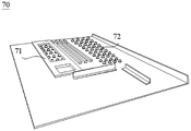
In another embodiment of the present invention, as shown in fig. 1 and 4, the filter element recycling apparatus further includes a carrier transport area 70 and a station 80. The first lifting device 23, the carrier conveying area 70 and the operation table 80 are sequentially arranged along the circulation direction of the carrier circulation device 20; the carrier conveying area 70 is provided with a push plate 71 and a plurality of conveying balls 72 are uniformly arranged, specifically, the conveying balls 72 are universal balls. The first lifting device 23 transfers the carrier 10 to the carrier transfer area 70, the push plate 71 pushes the carrier 10 to one side, and the transfer balls 72 transfer the carrier 10 to the operation table 80.
In another embodiment of the present invention, as shown in fig. 1 and 5, the filter cartridge recycling production equipment further includes a filter cartridge flattening device 90, and the filter cartridge flattening device 90 is located between the welt device 30 and the first lifting device 23.
The filter element flattening device 90 includes a filter element flattening frame 93, two top surface flattening plates 91, and two side surface flattening plates 92. The two side surface flattening combined plates 92 are symmetrically arranged on the filter element flattening frame 93, and the two top surface flattening plates 91 are symmetrically arranged on the filter element flattening frame 93 and are positioned between the two side surface flattening combined plates 92. The top surface flattening plate 91 is used for flattening the top surface of the filter element, and the side surface flattening plate group 92 is used for flattening the left side surface and the right side surface of the filter element. Filter core flattening device 90 flattening filter core guarantees the degree of accuracy of welt, prevents that the strake from pasting askew wrong. Specifically, each top surface flattening plate 91 and each side surface flattening plate group 92 are connected with an air cylinder, and the air cylinder drives the two side surface flattening plate groups 92 to horizontally reciprocate, so that the left side surface and the right side surface of the filter element are flattened respectively; the pressing plates 91 on the two top surfaces of the cylinder move up and down, so that the top surfaces of the filter elements are pressed flatly.
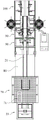
In another embodiment of the present invention, as shown in fig. 6 to 7, the welting device 30 includes two welting mechanisms 31, the two welting mechanisms 31 are respectively disposed on two sides of the upper rail 21, and the two welting mechanisms 31 simultaneously and respectively welt the filter element.
The two edge pasting mechanisms 31 respectively comprise an edge strip tray 32, a guide roller 33 and at least one gluing mechanism 34, and the guide roller 33 guides edge strips on the edge strip tray 32 to the filter cores; the glue spreading mechanism 34 sends glue to the edge strips, and the edge strips after gluing are attached to the filter cores and move on the upper rail 21 along with the filter cores.
In this embodiment, the welt device 30 includes a welt main part 301, the welt mechanism 31 sets up in the welt main part 301, the welt main part 301 is equipped with a charging tray support 303 that has the erection column 302 to protruding respectively, two strip charging trays 32 overlap respectively and establish two on the erection column 302 and rotate and connect the charging tray support 303, guide roll 33 sets up on the welt main part 301, and is close to the setting of upper track 21, glue spreader 34 sets up on the welt main part 301, and glue spreader 34 is close to the setting of guide roll 33, the invention adopts welt mechanism 31, carries out automatic welt to filter core both sides limit for the strake with the welt adhesion surface is more accurate laminating, has reduced the cost of labor, and easy operation increases the homogeneous homogeneity and the stability of welt.
In another embodiment of the present invention, as shown in fig. 8-9, the glue coating mechanism 34 includes a glue discharging assembly 35, a height adjusting bracket 36 and a sliding table cylinder 37; go out gluey subassembly 35 and install on height adjustment frame 36, height adjustment frame 36 is adjustable go out gluey subassembly 35's position height, height adjustment frame 36 is installed on the slip table cylinder 37, slip table cylinder 37 drives go out gluey subassembly 35 and be close to or keep away from the strake. Height adjustment frame 36 is in the lifting go out gluey subassembly 35's position height the time, can be for go out gluey subassembly 35's removal obligate space, so as to do benefit to height adjustment frame 36 is right go out gluey subassembly 35 and wait that the distance between the rubber coating strake is adjusted.
The height adjustment frame 36 includes an upper plate 361, a lower plate 362, two sliding rails 363, a screw 364, and a slider 365. The lower plate 362 is fixed on the driving end 366 of the sliding table cylinder and slides back and forth along with the driving end 366, the upper plate 361 and the lower plate 362 are respectively fixed at two ends of the two sliding rails 363, the sliding block 365 is fixedly connected with the glue discharging component 35, the sliding block 365 is located between the upper plate 361 and the lower plate 362 and can movably move up and down along the sliding rails 363, the screw rod 364 sequentially penetrates through the upper plate 361, the sliding block 365 and the lower plate 362, and the screw rod 364 drives the sliding block 365 to move up and down. The glue discharging assembly 35 may also be a screw and a hand handle, the driving end 366 may be a sliding structure with a linear guide rail matching with the sliding block 365, the driving end 366 is connected to a screw with a hand handle, and a user rotates the hand handle to drive the screw to rotate so as to drive the driving end 366 to move, thereby driving the glue discharging assembly 35 to approach or leave the edge strip.
The glue discharging assembly 35 includes a glue discharging head 351 and a glue amount adjusting stick 353. Go out to be formed with out gluey passageway in the gluey head 351, just it has out gluey mouth 352 to go out gluey head 351, go out gluey mouth 352 and be used for going out gluey just it is close to go out gluey mouth 352 strake setting, it communicates respectively to go out gluey passageway go out gluey mouth 352 and external storage and glue the case, it has movably inserted gluey volume adjustment stick 353 to go out gluey passageway, makes the space that passes through of going out gluey passageway diminishes, and then reduces the play gluey volume of going out gluey mouth 352, adjusts the size of a gluey passageway to adjust out gluey volume of the play of mouthful 352. The user can insert or extract according to the demand of the volume of glue of going out glue volume adjust rod 353, and the flexibility is good and the practicality is high.
Through set up altitude mixture control spare on rubber coating mechanism 34, inject the glue film thickness on the opposite side strip, guaranteed the homogeneity of glue film thickness, and then promoted product quality.
Wherein, rubber coating mechanism 34 still includes two hold-in ranges 21, two hold-in ranges 21 locates respectively go up track 21's both sides, two behind the hem is pressed respectively to hold-in ranges 21's medial surface the filter core and with 20 synchronous motion of conveyer belt. Wherein, hold-in range 21 is the annular, and on two synchronous pulley 201 were located to each hold-in range 21's both ends adaptation cover, synchronous pulley 201 passed through the connecting axle and changeed on connecing main part 301, synchronous pulley 201 was rotated by its rotation of outside motor drive to drive hold-in range 21 and remove, increase strake 111 with the stability of gluing between the filter core improves the quality of filter core welt.
In another embodiment of the present invention, as shown in fig. 1 to 3, the filter element recycling production apparatus further includes a first blower 100, the first blower 100 is located between the edge attaching device 30 and the edge trimming device 40, and the first blower 100 is used for air drying the glue. The side strips with the glue are prevented from being adhered to the edge shearing device 40, so that the normal work of the edge shearing device 40 and the subsequent processes are prevented from being influenced.
In another embodiment of the present invention, as shown in fig. 1-3, the filter element recycling apparatus further comprises a second blower 110, the second blower 110 is located between the trimming device 40 and the transferring device 50, and the second blower 110 is used for air drying the glue. The adhesive edge strips are prevented from being adhered to the trimming device 60, and the normal work of the trimming device 60 and the subsequent processes are prevented from being influenced.
In another embodiment of the present invention, as shown in fig. 10-13, the carrier 10 is provided with a filter cartridge support base 11, the filter cartridge support base 11 includes a bottom plate 12 and a plurality of partition plates 13, the plurality of partition plates 13 are uniformly disposed on the bottom plate 12, and a paper jam gap 14 is formed between every two partition plates 13, and the paper jam gap 14 is used for placing and positioning the filter cartridge. The filter core has a plurality of kink, and is a plurality of the kink stretches into respectively a plurality of in the card paper clearance 14, the filter core easily takes off carrier 10, the difficult skew that takes place in position of filter core, and stability is good, makes things convenient for the processing of follow-up filter core, has guaranteed the quality of welt, and the practicality is high.
As shown in fig. 14 to 16, the transfer device 50 includes a stand 510, a transplanting assembly 520, a transplanting frame 530 and a feeding device 300. The stand 510 is installed above the trimming device 60, the transplanting assembly 520 is installed on the top of the stand 510, and the transplanting frame 530 is installed on the transplanting assembly 520, and the transplanting frame 530 is driven by the transplanting assembly 520 to reciprocate horizontally. The two feeding devices 300 are symmetrically arranged on the transplanting frame 530. Specifically, the transplanting assembly 520 may be a linear module, and the transplanting frame 530 is mounted on a moving end of the linear module, and the transplanting frame 530 is driven by the linear module to reciprocate horizontally.
Specifically, as shown in fig. 14-16, the feeding device 300 includes a feeding assembly 310 and a longitudinal transplanting mechanism (not shown). The longitudinal transplanting mechanism is arranged on the feeding device 300, the feeding device 30 is arranged on the longitudinal transplanting mechanism, and the feeding component 310 is driven to move up and down through the longitudinal transplanting mechanism. Specifically, the longitudinal transplanting mechanism may be an air cylinder or other driving structure, and the feeding assembly 310 is driven to move up and down by the telescopic motion of the air cylinder.
As shown in fig. 14 to 16, the feeding assembly 310 further includes two opposite clamping jaws 301, the two clamping jaws 301 are respectively connected to the longitudinal transplanting mechanism through a connecting plate 303, a filter element clamping position is formed between the two clamping jaws 301, and the two clamping jaws 301 respectively clamp two ends of the filter element. Two clamping jaw 301 restriction the position of filter core prevents that the slitter edge position of filter core from taking place the skew, guarantees the quality of cutting.
In other embodiments, as shown in fig. 14-16, the feeding assembly 310 further comprises a finger cylinder or a pneumatic finger cylinder (not shown), and the finger cylinder is mounted on the longitudinal transplanting mechanism. The two clamping jaws 301 are respectively installed on two fingers of the finger cylinder through connecting plates 303, the two clamping jaws 301 are driven to move in an opening and closing mode through the finger cylinder, and therefore the two clamping jaws 301 can respectively clamp two ends of the filter element. Specifically, the two clamping jaws 301 clamp the filter element, and then the filter element on the two clamping jaws 301 is driven to be transplanted on the trimming device 60 through the transplanting assembly 520 and the longitudinal transplanting mechanism.
In another embodiment of the present invention, as shown in fig. 16, the feeding assembly 310 is further provided with a positioning pressing plate 302, and the upper end of the positioning pressing plate 302 is connected with a guide rod, and the guide rod is slidably connected to the transplanting frame 530 through a guide sleeve. The bottom surface of the positioning pressing plate 302 is abutted against the top surface of the filter element, and other external forces except the self gravity of the positioning pressing plate 302 are abutted against the top surface of the filter element, so that the cutting quality of the filter element is ensured, and the position deviation of the waste edge of the filter element is prevented.
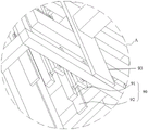
In another embodiment of the present invention, as shown in fig. 14-16, the trimming device 60 includes a bracket 61 and at least one trimming blade unit 62, and at least one trimming blade unit 62 is movably disposed on the bracket 61. In a specific embodiment, the number of the trimming blade sets 62 is four, and four trimming blade sets 62 are uniformly distributed on the bracket 61.
As shown in fig. 14-16, the trimming blade set 62 includes a fixed blade 63 and a movable blade 64, the fixed blade 63 and the movable blade 64 are parallel and opposite to each other, and a material placing gap 65 is formed between the fixed blade 63 and the movable blade 64. The movable knife 64 is externally connected with a driving device, and the driving device drives the movable knife 64 to do reciprocating motion; the waste edge of the filter element extends into the material placing gap 65, and the movable knife 64 moves towards the fixed knife 63 and cuts off the waste edge of the filter element. The driving device can be a device which can do reciprocating motion, such as an air cylinder. The trimming device 60 is simple in structure, reasonable in design and convenient to operate, automatically shears the waste edges in the filter element after trimming, improves the efficiency and accuracy of shearing waste materials, improves the quality of the filter element, reduces the production cost of the filter element, reduces the labor intensity of operators, and avoids the problem that the filter element is uneven due to manual trimming and the quality of the filter element is difficult to guarantee.
Further, as shown in fig. 14-16, the movable blade 64 is obliquely disposed. The movable knife 64 and the fixed knife 63 can cut the waste edges more easily, and the waste edge cutting efficiency is improved.
Further, as shown in fig. 14-16, the trimming blade set 62 further includes a second fixed member 66 and a first stop plate 67, the movable blade 64 is fixed on the second fixed member 66, the trimming blade set 62 further includes a push plate 68, and the push plate 68 is located between the second fixed member 66 and the first stop plate 67; the pushing plate 68 is connected with an air cylinder, and the air cylinder drives the pushing plate 68 to move upwards to push and cut waste materials. The pushing plate 68 prevents the trimmed waste edge from entering the trimming knife set 62 to affect the cutting of the movable knife 64 and the fixed knife 63, or prevents the waste material from being retained in the material placing gap 65 to affect the normal operation of the trimming device 60.
Further, as shown in fig. 14-16, the trimming blade set 62 further includes at least one blowing device, and at least one blowing device blows air to align with the material placing gap 65. The blowing device blows off the cut waste edges, so that the cut waste edges are prevented from remaining on the movable knife 64 or the fixed knife 63 or remaining in the material placing gap 65, and the waste edges in the next filter element after being attached with edges are prevented from being cut by the trimming knife set 62.
Specifically, the blowing device can be a structure of a blowing pipe and an air pump, high-pressure air is provided for the blowing pipe through the air pump, the blowing pipe is aligned to the material placing gap 65, the high-pressure air is blown out from the blowing pipe to blow off the sheared waste edges, and the structure is simple.
In another embodiment of the present invention, as shown in fig. 14 to 15, the trimming device 60 further includes an air blowing anti-sticking air gun for blowing away the cutting waste and a release agent spraying anti-sticking air gun for spraying the release agent, specifically, the air blowing anti-sticking air gun blows air when cutting the edge each time, the release agent spraying anti-sticking air gun sets the number of spraying times according to the actual requirement, and when the number of cut edges reaches the set number, the release agent spraying is performed once, and the time of spraying is set according to the requirement. The blowing anti-sticking air gun and the release agent spraying anti-sticking air gun can prevent residual glue from attaching to the material placing gap 65 to affect the normal work of the trimming device 60.
The structure and the working principle of the edge trimming device 40 are substantially the same as those of the trimming device 60, and therefore, for the specific structure of the edge trimming device 40 for trimming the filter element after the edge strip, details are not repeated herein in this embodiment.
The above description is only for the purpose of illustrating the preferred embodiments of the present invention and is not to be construed as limiting the invention, and any modifications, equivalents and improvements made within the spirit and principle of the present invention are intended to be included within the scope of the present invention.
Claims (10)
1. A filter core circulation production facility which characterized in that includes:
a plurality of carriers for carrying filter elements;
a carrier circulation device for circulating the transport carrier;
the welting device is used for welting the filter element;
the edge shearing device is used for roughly shearing the filter element after the edge strips are attached;
the transfer device is used for transferring the filter element after rough shearing;
the trimming device is used for trimming the filter element transferred by the transfer device; and
the finishing device is used for finishing the final product; the edge attaching device, the edge shearing device, the transferring device, the trimming device and the arranging device are sequentially arranged along the circulating direction of the carrier circulating device.
2. The filter element recycling production apparatus according to claim 1, wherein the carrier recycling device comprises a frame, an upper rail and a lower rail disposed on the frame up and down, and a first lifting device and a second lifting device disposed at two ends of the upper rail respectively, the carrier moves from a start end of the upper rail to the first lifting device, the first lifting device transfers the carrier to the lower rail, the carrier moves along with the lower rail to the second lifting device, and the second lifting device transfers the carrier to the upper rail.
3. The filter element recycling production apparatus according to claim 2, further comprising a carrier conveying area and a console, wherein the first lifting device, the carrier conveying area and the console are sequentially arranged along a recycling direction of the carrier recycling device; the carrier conveying area is provided with a push plate, a plurality of conveying ball pieces are uniformly arranged on the push plate, the first lifting device conveys the carrier to the operating platform, the push plate pushes the carrier to one side, and the conveying ball pieces convey the carrier to the operating platform.
4. The filter cartridge recycling production apparatus of claim 2, further comprising a filter cartridge flattening apparatus; the filter element flattening device is positioned between the welt attaching device and the first lifting device and comprises a filter element flattening frame, two top surface flattening plates and two side surface flattening assembly plates; the two side surface flattening plates are symmetrically arranged on the filter element flattening frame, and the two top surface flattening plates are symmetrically arranged on the filter element flattening frame and positioned between the two side surface flattening plates; the top surface is pressed the flat top surface that is used for flattening the filter core, the group board that flattens in the side is used for flattening the left surface and the right flank of filter core.
5. Filter cartridge recycling production apparatus according to claim 2, wherein the welt means comprises two welt mechanisms; the two welting mechanisms are respectively arranged at two sides of the upper track, and are used for respectively welting the filter element at the same time; the two edge pasting mechanisms respectively comprise an edge strip tray, a guide roller and at least one gluing mechanism; the guide roller guides the edge strips on the edge strip material tray to the filter element; the glue spreading mechanism sends glue to the edge strips, and the edge strips after gluing are attached to the filter element and move on the upper rail along with the filter element.
6. The filter element recycling production equipment according to claim 5, wherein the glue coating mechanism comprises a glue outlet assembly, a height adjusting frame and a sliding table cylinder; the height adjusting frame is arranged on the sliding table cylinder, and the sliding table cylinder drives the glue outlet assembly to be close to or far away from the edge strip;
the glue outlet assembly comprises a glue outlet head and a glue amount adjusting stick; a glue outlet channel is formed in the glue outlet head, the glue outlet head is provided with a glue outlet, the glue outlet is used for discharging glue, the glue outlet is arranged close to the edge strips, and the glue outlet channels are respectively communicated with the glue outlets; the glue quantity adjusting rod is movably inserted into the glue outlet channel, and the glue outlet quantity of the glue outlet assembly is adjusted by inserting or pulling out the glue quantity adjusting rod.
7. The filter element recycling production apparatus of any one of claims 1 to 6, further comprising a first fan positioned between said welt attachment means and said edge trimming means, said first fan being adapted to air dry glue.
8. Filter element recycling production plant according to any of claims 1 to 6, further comprising a second fan located between said trimming means and said transferring means, said second fan being adapted to dry the glue.
9. The filter element recycling apparatus as recited in any one of claims 1 to 6, wherein said carrier has a filter element support base, said filter element support base comprising a bottom plate and a plurality of partition plates, said plurality of partition plates being uniformly disposed on said bottom plate, and a paper jam gap being formed between every two of said partition plates, said paper jam gap being used for placing and positioning the filter element.
10. The filter element recycling production plant according to any of claims 1 to 6, wherein the trimming device comprises a support, at least one trimming blade set and a feeding device; at least one trimming knife group is movably arranged on the bracket; the trimming knife group comprises a fixed knife and a movable knife; the fixed cutter and the movable cutter are parallel and opposite to each other, and a material placing gap is formed between the fixed cutter and the movable cutter; the movable knife is externally connected with a driving device, and the driving device drives the movable knife to do reciprocating motion; the feeding device is positioned at the upper end of the bracket, and clamps the filter element to move up and down movably; during trimming, the feeding device clamps the filter element and moves downwards to the trimming knife set, the waste edge of the filter element extends into the material placing gap, and the movable knife moves towards the fixed knife and cuts off the waste edge of the filter element;
and/or the trimming device also comprises a push plate, the push plate is connected with an air cylinder, and the air cylinder drives the push plate to move upwards to push and cut the waste materials;
and/or, the trimming device also comprises a blowing anti-sticking air gun and a demolding agent spraying anti-sticking air gun, wherein the blowing anti-sticking air gun is used for blowing away the cutting waste materials, and the demolding agent spraying anti-sticking air gun is used for spraying the demolding agent.
Priority Applications (1)
| Application Number | Priority Date | Filing Date | Title |
|---|---|---|---|
| CN202210718065.4A CN115179596A (en) | 2022-06-23 | 2022-06-23 | Filter core circulation production facility |
Applications Claiming Priority (1)
| Application Number | Priority Date | Filing Date | Title |
|---|---|---|---|
| CN202210718065.4A CN115179596A (en) | 2022-06-23 | 2022-06-23 | Filter core circulation production facility |
Publications (1)
| Publication Number | Publication Date |
|---|---|
| CN115179596A true CN115179596A (en) | 2022-10-14 |
Family
ID=83515321
Family Applications (1)
| Application Number | Title | Priority Date | Filing Date |
|---|---|---|---|
| CN202210718065.4A Pending CN115179596A (en) | 2022-06-23 | 2022-06-23 | Filter core circulation production facility |
Country Status (1)
| Country | Link |
|---|---|
| CN (1) | CN115179596A (en) |
-
2022
- 2022-06-23 CN CN202210718065.4A patent/CN115179596A/en active Pending
Similar Documents
| Publication | Publication Date | Title |
|---|---|---|
| TW201524850A (en) | Labeling device | |
| CN110039926B (en) | Efficient production process of books | |
| CN111229531A (en) | Rubber coating banding production line | |
| CN110759160B (en) | Automatic EVA (ethylene-vinyl acetate) adhesive film cutting and collecting machine | |
| CN113276534A (en) | Automatic compound equipment of package RFID drop | |
| CN107321869A (en) | Planing tool blade automatic blanking collating unit | |
| CN210558465U (en) | Equipment is tailor to air filter screen hem | |
| CN106347737B (en) | A kind of profile automatic coating equipment and its set film method | |
| CN217944516U (en) | Filter core circulation production facility | |
| CN115179596A (en) | Filter core circulation production facility | |
| CN208731304U (en) | A kind of film paper automatic stripper | |
| CN112960177B (en) | Carton sticking film machine | |
| US20210379920A1 (en) | Additional member attaching apparatus and binding system including the same | |
| CN108493475B (en) | Automatic battery edge wrapping machine | |
| CN111498577A (en) | Metal foil material loading equipment | |
| CN113815302A (en) | Multi-mesh-belt screen printing machine | |
| CN108725909B (en) | Flexible automatic film scribing device and film scribing method thereof | |
| CN219600547U (en) | Full-automatic flank leather shell equipment of borduring | |
| CN213291060U (en) | Ceiling dry method automatic production line | |
| CN218594651U (en) | Full-automatic door pocket production line | |
| CN215037874U (en) | Abalone slice cutting machine | |
| CN219487943U (en) | Bar code pasting equipment | |
| CN217458207U (en) | Novel full-automatic slitting machine | |
| CN217944515U (en) | Welt mechanism and filter core welt device | |
| CN215790430U (en) | Plate splicing machine |
Legal Events
| Date | Code | Title | Description |
|---|---|---|---|
| PB01 | Publication | ||
| PB01 | Publication | ||
| SE01 | Entry into force of request for substantive examination | ||
| SE01 | Entry into force of request for substantive examination |