CN115108688A - System and method for comprehensively treating wastewater in white spirit production - Google Patents
System and method for comprehensively treating wastewater in white spirit production Download PDFInfo
- Publication number
- CN115108688A CN115108688A CN202210915563.8A CN202210915563A CN115108688A CN 115108688 A CN115108688 A CN 115108688A CN 202210915563 A CN202210915563 A CN 202210915563A CN 115108688 A CN115108688 A CN 115108688A
- Authority
- CN
- China
- Prior art keywords
- sludge
- module
- tank
- stirring
- fermentation
- Prior art date
- Legal status (The legal status is an assumption and is not a legal conclusion. Google has not performed a legal analysis and makes no representation as to the accuracy of the status listed.)
- Granted
Links
Images


Classifications
-
- C—CHEMISTRY; METALLURGY
- C02—TREATMENT OF WATER, WASTE WATER, SEWAGE, OR SLUDGE
- C02F—TREATMENT OF WATER, WASTE WATER, SEWAGE, OR SLUDGE
- C02F9/00—Multistage treatment of water, waste water or sewage
-
- C—CHEMISTRY; METALLURGY
- C02—TREATMENT OF WATER, WASTE WATER, SEWAGE, OR SLUDGE
- C02F—TREATMENT OF WATER, WASTE WATER, SEWAGE, OR SLUDGE
- C02F11/00—Treatment of sludge; Devices therefor
-
- C—CHEMISTRY; METALLURGY
- C02—TREATMENT OF WATER, WASTE WATER, SEWAGE, OR SLUDGE
- C02F—TREATMENT OF WATER, WASTE WATER, SEWAGE, OR SLUDGE
- C02F11/00—Treatment of sludge; Devices therefor
- C02F11/02—Biological treatment
-
- C—CHEMISTRY; METALLURGY
- C02—TREATMENT OF WATER, WASTE WATER, SEWAGE, OR SLUDGE
- C02F—TREATMENT OF WATER, WASTE WATER, SEWAGE, OR SLUDGE
- C02F11/00—Treatment of sludge; Devices therefor
- C02F11/02—Biological treatment
- C02F11/04—Anaerobic treatment; Production of methane by such processes
-
- C—CHEMISTRY; METALLURGY
- C02—TREATMENT OF WATER, WASTE WATER, SEWAGE, OR SLUDGE
- C02F—TREATMENT OF WATER, WASTE WATER, SEWAGE, OR SLUDGE
- C02F11/00—Treatment of sludge; Devices therefor
- C02F11/12—Treatment of sludge; Devices therefor by de-watering, drying or thickening
-
- C—CHEMISTRY; METALLURGY
- C02—TREATMENT OF WATER, WASTE WATER, SEWAGE, OR SLUDGE
- C02F—TREATMENT OF WATER, WASTE WATER, SEWAGE, OR SLUDGE
- C02F1/00—Treatment of water, waste water, or sewage
- C02F1/001—Processes for the treatment of water whereby the filtration technique is of importance
-
- C—CHEMISTRY; METALLURGY
- C02—TREATMENT OF WATER, WASTE WATER, SEWAGE, OR SLUDGE
- C02F—TREATMENT OF WATER, WASTE WATER, SEWAGE, OR SLUDGE
- C02F1/00—Treatment of water, waste water, or sewage
- C02F1/52—Treatment of water, waste water, or sewage by flocculation or precipitation of suspended impurities
-
- C—CHEMISTRY; METALLURGY
- C02—TREATMENT OF WATER, WASTE WATER, SEWAGE, OR SLUDGE
- C02F—TREATMENT OF WATER, WASTE WATER, SEWAGE, OR SLUDGE
- C02F1/00—Treatment of water, waste water, or sewage
- C02F1/66—Treatment of water, waste water, or sewage by neutralisation; pH adjustment
-
- C—CHEMISTRY; METALLURGY
- C02—TREATMENT OF WATER, WASTE WATER, SEWAGE, OR SLUDGE
- C02F—TREATMENT OF WATER, WASTE WATER, SEWAGE, OR SLUDGE
- C02F2103/00—Nature of the water, waste water, sewage or sludge to be treated
- C02F2103/32—Nature of the water, waste water, sewage or sludge to be treated from the food or foodstuff industry, e.g. brewery waste waters
- C02F2103/325—Nature of the water, waste water, sewage or sludge to be treated from the food or foodstuff industry, e.g. brewery waste waters from processes relating to the production of wine products
-
- C—CHEMISTRY; METALLURGY
- C02—TREATMENT OF WATER, WASTE WATER, SEWAGE, OR SLUDGE
- C02F—TREATMENT OF WATER, WASTE WATER, SEWAGE, OR SLUDGE
- C02F3/00—Biological treatment of water, waste water, or sewage
- C02F3/30—Aerobic and anaerobic processes
Abstract
The invention belongs to the technical field of sewage treatment, and discloses a comprehensive treatment system for liquor production wastewater, which comprises sewage connected through a pipelineThe sewage treatment module comprises a coagulation sedimentation tank and a sludge treatment module A 2 A/0 tank and an MBR membrane tank, A 2 The anoxic tank of the/0 tank is provided with a greenhouse gas collector A 2 The anoxic tank and the aerobic tank of the/0 tank are both provided with ultrasonic modules; the high-temperature composting mechanism comprises a sludge primary fermentation module, a sludge secondary fermentation module and a vinasse feed module, wherein the sludge primary fermentation module is connected with a planting greenhouse connected with a biological fattening greenhouse through a pipeline.
Description
Technical Field
The invention belongs to the technical field of sewage treatment, and particularly relates to a comprehensive treatment system and method for liquor production wastewater.
Background
According to estimation, when 1 ton of liquor with 65 degrees is elongated, about 60 tons of water are consumed, 48 tons of produced wastewater and large discharge capacity are discharged, and GB27631-2011 'emission standard for pollution of fermented alcohol and liquor industrial water' is newly issued by China aiming at the emission of liquor wastewater, so that liquor enterprises need to pay attention to the treatment work of wastewater and strictly control the discharge of wastewater, the wastewater produced in the liquor production process mainly has the characteristics that most of the wastewater produced in the liquor production process comes from low-boiler wastewater produced by a liquor brewing retort stove, no other industrial wastewater and domestic wastewater enter, the organic matter content is high, and the content range is 500-900gKg -1 Average 793.23gKg -1 While the average content of organic matters in the pure pig manure is 714gKg -1 For another example, the COD concentration is up to 15000mgL -1 Meanwhile, the sludge contains nutrient elements necessary for plant growth, which can partially replace chemical fertilizers, and the Chinese municipal sludge contains rich nutrient elements of nitrogen, phosphorus and potassium, and the average content is 27.0, 14.3 and 7.0gKg -1 While the average content of nitrogen, phosphorus and potassium nutrient elements in the white spirit sludge is 44.79, 38.44 and 3.42gKg -1 The sludge is mostly weakly acidic, the water content of the sludge is 60-80%, the heavy metal content of the sludge is low, the heavy metal in the sludge is various, copper, lead, zinc, forceps, mercury, cadmium and the like are the most main obstacles influencing the resource utilization of the sludge, and the average value of arsenic, cadmium, chromium, copper, mercury, forceps, lead and zinc in municipal sludge in China is 20.2 and 2.01、93.1、219、2.13、48.7、72.3、1058 mgKg -1 The average values of chromium, lead, cadmium, arsenic and mercury in the wastewater of the raw white spirit production are 98.83 mgKg, 16.59 mgKg, 1.94 mgKg, 1.9 mgKg and 0.47mgKg -1 It can be seen that the average chromium content is close to the average chromium content of the Chinese municipal sludge, the contents of other elements are far lower than the average chromium content of the Chinese municipal sludge, the sludge dry heat value is larger, and the heat value range of the Chinese municipal sludge is 5830- -1 The mean value is 11850 KJ Kg -1 The average value of the dry heat value of the waste water and sludge of the white spirit is 18923 KJ Kg -1 The average heat value of the biological treatment effluent is equivalent to that of sawdust, most of the traditional wastewater and sludge treatment modes are modes of sanitary landfill, incineration, throwing into the sea, direct land utilization and the like, the resource utilization of the sludge is started late, the sludge treatment equipment is complex and has higher cost, small and medium-sized wineries are unwilling to spend huge cost and directly discharge the wastewater, the environmental pollution is larger, meanwhile, the pollutants in the wastewater are degraded by microorganisms in the traditional wastewater treatment process, and simultaneously a large amount of soluble microorganism products, SMP for short, are not degraded, some SMP are even difficult to degrade, the existence of the SMP has great influence on the biological treatment process, on one hand, COD and BOD5 in the biological treatment effluent are improved, the discharge standard is difficult to reach, on the other hand, the effluent has toxicity, many SMP are precursors for forming chlorinated organic matters, when chlorination disinfection is carried out, SMP can be converted into toxic or carcinogenic chloride, and in addition, high concentrations of SMP can also seriously affect the dynamic activity and flocculation and sedimentation characteristics of activated sludge.
Disclosure of Invention
The invention aims to adjust and absorb SMP in the sewage treatment process through a dosing module and an active carbon adsorption module, reduce SMP content, reduce interference on activated sludge, perform fattening and disinfection treatment on the sludge through a planting greenhouse and a biological fattening greenhouse, and use the sludge in agricultural production, and simultaneously produce bioprotein for breeding industry, reduce pollution to the environment and increase the income of a winery.
Based on the purpose, the invention adopts the following technical scheme: liquor production wasteThe water comprehensive treatment system comprises a sewage treatment module, a sludge treatment module and a control module which are connected through pipelines, wherein the sewage treatment module comprises a filtering tank, an adjusting tank, a coagulating sedimentation tank and a tank A which are communicated with each other 2 The sludge treatment module comprises a concentration tank, a high-temperature composting mechanism, a biological fertility increasing shed and a biological protein treatment module which are connected, and is characterized in that: a is described 2 The anoxic pond of the/0 pond is provided with a greenhouse gas collector and a sludge discharge mechanism A 2 An ultrasonic module is arranged on the anoxic tank and the aerobic tank of the/0 tank; the high-temperature composting mechanism comprises a sludge primary fermentation module, a sludge secondary fermentation module and a vinasse feed module, and a planting greenhouse connected through a pipeline is arranged between the sludge primary fermentation module and the biological fattening greenhouse.
Preferably, a primary mixing tank, a secondary mixing tank and a transduction tank which are formed by dividing the anoxic tank by a vertical baffle are arranged in the anoxic tank, and an anoxic tank cover is arranged on the anoxic tank; the anoxic tank cover comprises a side plate surrounding the anoxic tank, an air guide cover arranged on the side plate and covering the primary mixing tank and the secondary mixing tank, support columns with different lengths are arranged between the air guide cover and different baffle plates, so that the air guide cover is inclined, the inclination angle is 10-20 degrees, the anoxic tank cover also comprises a hemispherical air gathering cover arranged on the side plate and used for shielding the transduction tank, a flat maintenance cover is arranged between the air gathering covers, and the air guide cover, the air gathering cover and the maintenance cover are integrally connected with the side plate; the greenhouse gas collector comprises a pool outer part arranged on the outer side surface of the anoxic pool and a pool inner part arranged in the gas gathering cover, the pool outer part comprises a negative pressure fan, a gas collecting tank and a processing module, the pool inner part comprises a water lower part, a water surface part and a water upper part, the water lower part comprises a plurality of vent pipes communicated with the water surface part, the vent pipes comprise methane gas-permeable films, water-permeable films are sleeved on the methane gas-permeable films, and three-level gas conveying pipes communicated with the water surface part are arranged in the methane gas-permeable films; the surface of water portion is including the square methane collection pad that there is not several miniature gas pocket in inside, methane collection pad on be equipped with the water barrier of surface of water contact, the water barrier is connected with the integration of portion under water, methane collection pad is equipped with a plurality of second grade gas-supply pipes that are linked together with tertiary gas-supply pipe in being equipped with, second grade gas-supply pipe passes through miniature gas pocket and air intercommunication, methane collection pad is equipped with on be equipped with second grade gas-supply pipeA primary gas pipe communicated with the upper part of the water and communicated with the outside of the pool; the water upper part comprises a spherical gas collecting membrane matched with the gas gathering cover through a suspension wire, the distance between the spherical gas collecting membrane and the gas gathering cover is 2-3mm, the gas collecting membrane comprises a plurality of micro-tube gas permeable membrane layers with the distance of 1-2mm, the micro-tube gas permeable membrane layers comprise a plurality of gas permeable micro-tubes which are arranged along a hemispherical surface in a single-layer mode, and a heating module is arranged at the communication position of the gas collecting membrane and the primary gas conveying pipe; a heat exchange pipe connected with the combustion tank is arranged in the energy conversion tank; a sludge upper-reverse mechanism is arranged between the heat exchange tubes and comprises a stirring motor arranged on the outer side surface of the energy conversion pool, the stirring motor is connected with a driving roller arranged on the upper part in the energy conversion pool through a coupler, three sludge stirring belts are meshed on the driving roller, a hollowed sludge stirring groove is arranged on each sludge stirring belt, the sludge stirring device also comprises two auxiliary rollers in rolling fit with the sludge stirring belts, and the auxiliary rollers are arranged at the bottom of the energy conversion pool and are symmetrically arranged along the central line of the driving roller; coaxial reversing devices are arranged in the middle of the driving roller and the two auxiliary rollers, and the mud turning belts on the two sides of the driving roller and the two auxiliary rollers have the same turning direction and are opposite to the turning direction of the mud turning belts in the middle of the driving roller and the two auxiliary rollers; the greenhouse gas collector is communicated with a combustion tank, the combustion tank is communicated with the planting greenhouse, A 2 And a gas collection reverse hanging membrane is arranged on the anaerobic tank of the/0 tank.
Preferably, a dosing module is arranged outside the greenhouse gas collector, the dosing module comprises a medicine tank, a dosing pipeline communicated with the anoxic tank is arranged on the medicine tank, stirring modules matched with the dosing pipeline are arranged on the primary mixing tank and the secondary mixing tank, the stirring modules comprise stirring motors arranged on the air guide covers, and further comprise fixed cross rods arranged in the primary mixing tank and the secondary mixing tank, stirring shafts meshed with the stirring motors are arranged on the fixed cross rods, double-spiral stirring blades and stirring auxiliary blades are arranged on the stirring shafts, the stirring auxiliary blades are distributed on the stirring shafts along spiral lines and are perpendicular to the stirring shafts, the stirring directions of the stirring auxiliary blades are perpendicular to the spiral directions of the stirring blades, the stirring shafts are hollow and communicated with the dosing pipeline, the stirring auxiliary blades and the stirring blades are hollow and communicated with the stirring shafts, ultrasonic modules are arranged on the side faces of the stirring auxiliary blades, and the stirring shafts, The stirring blade and the stirring auxiliary blade are provided with medicine releasing holes.
Preferably, a mud discharging mechanism is arranged in the primary mixing tank and the secondary mixing tank, and the mud discharging mechanism is arranged on the inner bottom surface of the primary mixing tank and surrounds the inner side surface of the primary mixing tank for a circle; the sludge discharging mechanism comprises a concave surface-shaped net-shaped support fixed with the inner wall of the primary mixing pool, auxiliary wheels are arranged on the support, a sludge discharging belt in rolling fit with the auxiliary wheels is arranged on the concave surface of the support, limiting plates in sliding fit with the sludge discharging belt are arranged on two side surfaces of the support, sludge collecting plates perpendicular to the sludge discharging belt are arranged on the sludge discharging belt at equal intervals, each sludge collecting plate comprises a sludge collecting plate support connected with the limiting plates, an inner sleeve barrel with a hollow structure is arranged in each sludge collecting plate support, a lifting rod is arranged at the end, far away from the limiting plates, in each inner sleeve barrel, of each lifting rod, a lifting spring connected with the corresponding limiting plate is arranged on each lifting rod and is always in a compressed state, at least one arc-shaped dewatering rod is arranged in an inverted U-shaped gap between each inner sleeve barrel and each sludge collecting plate support, the plurality of dewatering rods are arranged along the U-shaped gaps to form a sludge collecting plate panel, and the dewatering rods at the tops of the inverted U-shaped gaps are fixedly connected with the lifting rods; a drainage rod temporary storage cavity matched with the inverted U-shaped gap is arranged on the sludge discharge belt, a sliding chute for controlling the position of the lifting rod is arranged on the front side wall in the primary mixing tank, a groove is formed in the middle of a support of three included angles in the primary mixing tank, a power mechanism matched with the sludge discharge belt is arranged in an area between the outer side surface of the support of the three included angles in the primary mixing tank and the inner wall surface of the primary mixing tank, and the power mechanism adopts a closed magnetic force non-contact transmission mechanism; the mud discharging mechanism further comprises a mud throwing mechanism arranged at the included angle position of the bottom surface between the front side wall and the baffle in the primary mixing tank, the mud throwing mechanism comprises mud falling grooves symmetrically arranged along the baffle, mud throwing motors are arranged on the side faces of the mud falling grooves, rotating shafts connected with the mud throwing motors through couplers are arranged in the mud falling grooves, and telescopic mud throwing plates are arranged on the rotating shafts.
Preferably, ultrasonic modules are arranged on two sides of the aerobic tank, and activated carbon adsorption modules are arranged in the aerobic tank and the MBR membrane tank; be equipped with the plant species and plant the module on the good oxygen pond, the plant species plants the module and collects the motor including the mud of establishing in the good oxygen pond outside, still include the mud floating collection module who is connected with the motor is collected to mud, the mud floating collection module is including establishing two parallel arrangement's in good oxygen pond roll axis, two roll axis go up the tensioning have the mud floating collection area, the mud floating collection takes the equidistant mud floating baffle that is equipped with, still including establishing the plant species plants lawn on good oxygen pond, be equipped with on the plant species plant lawn with mud floating baffle matched with scraper blade.
Preferably, the outer side surface of the sludge primary fermentation mechanism is provided with an ultrasonic module, and the sludge secondary fermentation mechanism and the vinasse feed module are communicated with the biological fattening shed; the biological weight-gaining shed comprises a fly raising module and a fly separating module which are communicated with each other, and also comprises an earthworm raising module, an earthworm separating module and a sludge disinfecting mechanism which are communicated with each other, wherein a sludge secondary fermentation mechanism is arranged between the earthworm raising module and the fly separating module; the fly and worm separating module and the earthworm separating module are connected with a protein processing module connected with the control module; the sludge primary fermentation mechanism comprises a spiral conveying mechanism communicated with a concentration tank, a sludge crushing module is arranged at the discharge end of the spiral conveying mechanism, a sludge conveying belt is arranged at the discharge port of the sludge crushing module, the sludge primary fermentation mechanism also comprises an auxiliary material conveying belt, an auxiliary material storage bin is arranged at the discharge end of the auxiliary material conveying belt, the auxiliary material storage bin is connected with the sludge conveying belt at the discharge port of the sludge crushing module through the auxiliary material conveying belt, a material mixing module is arranged at the discharge end of the sludge conveying belt, the discharge end of the material mixing module is connected with a gravity type sludge fermentation mechanism through the sludge conveying belt, a sludge vertical lifting module connected with the sludge conveying belt is arranged on the gravity type sludge fermentation mechanism, an air pump and a waste gas collecting and processing module are arranged on the gravity type sludge fermentation mechanism, the discharge end of the gravity type sludge fermentation mechanism is connected with a screening mechanism through the sludge conveying belt, and a discharge port at the lower layer of the screening mechanism is connected with a planting greenhouse, the upper layer discharge port of the screening mechanism is connected with the mixing module.
Preferably, the gravity type sludge fermentation mechanism comprises a grid support, a sludge fermentation bin is arranged on the grid support, a waste gas pipe communicated with the waste gas collecting and processing module is arranged on the outer side surface of the sludge fermentation bin, an oxygen conveying pipe communicated with an air pump is further arranged on the outer side surface of the sludge fermentation bin, a sludge feeding pipeline connected with the vertical lifting module is arranged at the top of the sludge fermentation bin, and a sludge conveying pipe communicated with the sludge fermentation bin is arranged on the sludge feeding pipeline; a four-layer fermentation chamber is arranged in the sludge fermentation bin, a waste gas collecting module communicated with a waste gas pipe is arranged at the top of the fermentation chamber on the fourth layer, the waste gas collecting module comprises a strip-shaped odor collecting pipe with a hollow structure, and an odor hole communicated with the fermentation chamber is arranged on the odor collecting pipe; an oxygen delivery module communicated with an oxygen delivery pipe is arranged on the waste gas collecting modules of the first layer, the second layer and the third layer of fermentation chambers, the oxygen delivery module comprises a pneumatic expansion plate arranged on the waste gas collecting module, a gas compressor is connected onto the pneumatic expansion plate through a pipeline, a hollow oxygen delivery device communicated with the oxygen delivery pipe is arranged on the pneumatic expansion plate, the oxygen delivery device comprises two parallel side wall plates, semicircular top plates are arranged on the side wall plates, the distance between the side wall plates is smaller than the diameter of the top plate by 1-2cm, oxygen outlet holes are formed in the parts, exceeding the side wall plates, of the top plates, close to the ends of the side wall plates, and the oxygen outlet holes are communicated with the oxygen delivery pipe through the hollow oxygen delivery device; the fermentation chamber is also internally provided with a sludge fermentation stirrer communicated with the oxygen conveying pipe, the sludge fermentation stirrer comprises a fermentation stirring motor arranged on the outer side surface of the sludge fermentation chamber, the sludge fermentation stirrer further comprises a stirring rotating shaft arranged in the fermentation chamber and connected with the fermentation stirring motor through a coupler, three planetary gear sets are arranged on the stirring rotating shaft along the axis, the transmission ratios of the three planetary gear sets are different, a planetary gear protective sleeve matched with the planetary gear sets is arranged on the stirring rotating shaft, a stirring coaxial reversing mechanism is arranged in the planetary gear protective sleeve positioned in the middle of the stirring rotating shaft, the outer side surface of each planetary gear set is provided with a stirring belt driving wheel, the outer side surface of each stirring belt is meshed with a stirring belt, a sludge gap convenient for sludge particles to pass through is arranged on each stirring belt, plough-type stirring crushing teeth are arranged on each stirring belt, a stirring oxygen mixing pipe communicated with the oxygen conveying pipe is arranged between the stirring belts, and an umbrella-shaped oxygen mixing device is arranged on each stirring oxygen mixing pipe.
Preferably, the planting greenhouse comprises a greenhouse body, the top of the greenhouse body is provided with a slope with an inclination angle of 20-50 degrees, a solar cell panel is arranged on the slope, and an arc-shaped transparent greenhouse top is arranged between the slopes; the shed body is provided with a sunlight leading-in system, the sunlight leading-in system comprises a sunlight collector arranged on the shed top, and also comprises an optical cable and a lamp arranged in the shed body; a spiral planting frame is also arranged in the shed body; the planting frame comprises a support, a conveying mechanism is arranged on the support, a plant planting belt is arranged on the conveying mechanism, a sludge coating mechanism located in the center of the spiral planting frame is further arranged in the shed body, the sludge coating mechanism comprises a mounting seat matched with the conveying mechanism, a sludge storage box communicated with a sludge conveying pipeline is arranged on the mounting seat, a plant seed sowing module matched with the sludge storage box is further arranged on the mounting seat, and a sludge discharging pipe and a sowing pipe matched with the conveying mechanism are arranged on the sludge storage box and the plant seed sowing module; a sludge leveling roller and a plough which are in sliding fit with the plant planting belt are arranged between the sludge blanking pipe and the seeding pipe, and a sludge leveling roller is also arranged on one side of the seeding pipe; the internal plant clearance mechanism that is equipped with the terminal matched with of plant frame of canopy, plant clearance mechanism include with transport mechanism sliding fit's side suspension type plant clearance module, be equipped with on the side suspension type plant clearance module and collect the clearance case with the fixed plant in ground, the transport mechanism below is equipped with mud transmission module, be equipped with on the mud transmission module be used for sifting out impurity and with the mud shale shaker that mud transmission module is linked together.
Preferably, the vinasse feed module adopts a vinasse fermentation mechanism; the fly breeding module comprises a stirring part and a breeding part, wherein the stirring part comprises a feed stirring mechanism communicated with the vinasse fermentation mechanism and the planting greenhouse; the feeding part comprises a cylindrical barrel body, and the top of the barrel body is provided with a feeding port communicated with the feed stirring mechanism; a servo motor connected with the control module is arranged at the upper part of the outer side surface of the barrel body, a rotating shaft matched with the servo motor is arranged in the barrel body, a spiral feeding substrate is arranged on the outer side surface of the rotating shaft, a sludge baffle plate is arranged on the outer side surface of the feeding substrate, an air pipe communicated with the outside and a water replenishing pipe communicated with a water outlet of the MBR membrane pool are arranged in the rotating shaft, and electromagnetic valves connected with the control module are arranged on the air pipe and the water replenishing pipe; a reticular water replenishing spray head communicated with the water replenishing pipe is arranged in the feeding substrate, and a heating module connected with the control module is also arranged; a temperature and humidity sensor communicated with the control module is also arranged in the barrel body; the fly and insect separation module adopts a centrifugal separation mechanism; the earthworm breeding module and the earthworm separation module are of the same structure as the fly breeding module and the fly separation module; sludge disinfection mechanism includes the shell, is equipped with the feed inlet that is linked together with earthworm separation module on the shell, is equipped with the ultraviolet module that is connected with control module in the shell, and exposure department at ultraviolet module is equipped with extrusion module, including establishing the extrusion motor at the shell lateral surface, still includes the squeeze roll of being connected with extrusion motor, still includes the mud scraper blade with squeeze roll complex, and the space between the mud scraper blade constitutes the mud passageway of platykurtic.
A comprehensive treatment method for liquor production wastewater comprises the following steps:
filtering sewage generated in the production of white spirit in a filtering tank, then entering an adjusting tank, adjusting the pH of the sewage by a medicine box, then entering a coagulating sedimentation tank, adding a coagulant to carry out sedimentation treatment on sludge, and sending the sludge into a concentration tank;
the sewage treated in the coagulating sedimentation tank enters A 2 The greenhouse gas generated in the anoxic pond is sent into the combustion tank through the greenhouse gas collector, the waste gas generated by combustion treatment is sent into the planting greenhouse to be absorbed and solidified by plants after heat exchange and desulfurization treatment, the greenhouse gas emission is reduced, and the heat generated by the combustion tank is sent into the high-temperature composting mechanism and the A 2 The/0 pool is used as a supplementary energy source and is fed to the A direction through a dosing module 2 Adding hydrogen peroxide and activated carbon into a/0 pool to control the SMP content in the sewage;
through A 2 The sewage treated in the/0 tank is sent into an MBR membrane tank for treatment, the SMP content in the MBR membrane tank is controlled by adding ibuprofen into the MBR membrane tank and controlling the retention time of sludge and the concentration of active carbon and DO, and the redundant sludge is sent into a concentration tank;
supernatant fluid of sludge in the concentration tank is fed into the regulating tank after concentration, the sludge enters a sludge primary fermentation mechanism for fermentation treatment, vinasse is fed into a vinasse feed mechanism for fermentation treatment of the vinasse, waste gas generated in the fermentation process is fed into a combustion tank, and the fermented sludge is fed into a planting greenhouse to absorb part of heavy metal in the sludge through absorption and transfer of plants;
stirring fermented vinasse and sludge by the sludge treated by the planting greenhouse through a feed stirring mechanism, feeding the sludge into a fly raising module, performing biological treatment on worm eggs and microorganisms in the sludge by using flies, and feeding mature flies into a protein treatment module after the fly separation module is used for treating, dehydrating and crushing the fly eggs and the microorganisms to prepare biological protein for raising poultry; the sludge is stirred together with fermented vinasse through the feed stirring mechanism after secondary fermentation and then is sent into the earthworm feeding module, the sludge texture is improved through earthworms, meanwhile, biological treatment is carried out on worm eggs and microorganisms in the sludge, the earthworms are separated out through the earthworm separating mechanism after the sludge is treated and then are sent into the protein treatment module to be made into poultry feed, and the separated sludge is irradiated and disinfected through the ultraviolet module in the sludge disinfecting mechanism to obtain the sludge capable of being used for fertilizing the field.
Compared with the prior art, the invention has the following beneficial effects: the invention can better and rapidly diffuse the medicine in the water body near the stirring blade by the double-spiral stirring blade in combination with the medicine releasing hole on the stirring blade, then drives the water body near the stirring shaft to move towards the direction far away from the stirring shaft by the stirring auxiliary blade to accelerate the mixing of the water body near the stirring shaft and the surrounding water body, and simultaneously combines the ultrasonic module to accelerate the diffusion of the medicine and promote the denitrification effect by utilizing the cavitation effect, the mechanical effect and the heat effect of ultrasonic waves and accelerate the gas production speed and the gas production rate of the water body, prolongs the time of the sludge in the water body by the sludge upper anti-mechanism in the energy conversion tank, increases the contact area with anaerobic bacteria and accelerates the denitrification speed and the gas production, cleans the sludge accumulated at the included angle of the anoxic tank by the sludge discharge mechanism, and avoids the problem that the sludge accumulated at the included angle of the anoxic tank is difficult to clean year by simultaneously feeding greenhouse gas generated in the sewage treatment process into the combustion tank for combustion, the generated heat is used for A in the present application 2 In the/0 pool and the high-temperature composting mechanism, the burnt carbon dioxide is sent into the planting greenhouse to be absorbed and solidified by plants, the emission of the carbon dioxide is reduced, the sludge is treated by the sludge primary fermentation mechanism and the sludge secondary fermentation mechanism, simultaneously, the generated waste gas is sent into the combustion tank to be combusted, the heavy metal in the sludge is absorbed and transferred by the plants absorbing the heavy metal, the treated sludge carries out biological treatment on microorganisms, ova and pathogens in the sludge by the fly breeding module and the earthworm breeding module, then the fly and the earthworm are treated by the protein treatment module to be prepared into poultry protein feed,meanwhile, residual vinasse is also treated, the improved sludge after earthworm treatment can be used for agricultural purposes after being irradiated and disinfected by X rays, and the income of a winery is increased 2 And the SMP content in sewage in the/0 tank is controlled by adding ibuprofen into the drug adding module MBR membrane tank and controlling the Sludge Retention Time (SRT) and DO concentration in the MBR membrane tank, so that the COD concentration of the effluent is lower.
Drawings
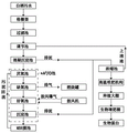
FIG. 1 is a schematic diagram of the work flow of a comprehensive treatment system for liquor production wastewater;
FIG. 2 is a schematic view of a sludge treatment module;
FIG. 3 is a schematic view of an anoxic tank;
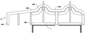
FIG. 4 is a schematic view of an anoxic tank cover;
FIG. 5 is a schematic view of a single gas permeable tube;
FIG. 6 is a schematic view of a methane collection pad;
FIG. 7 is a cross-sectional view of a methane collection pad;
FIG. 8 is a schematic view of the upper portion of the water;
FIG. 9 is a schematic view of a stirring module;
FIG. 10 is a top view of the mud discharge mechanism;
FIG. 11 is a cross-sectional view of a mud discharge mechanism;
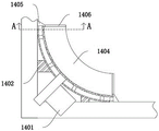
FIG. 12 is a schematic illustration of a mud collection pan support AA;
FIG. 13 is a schematic view of a mud collection plate bracket AA;
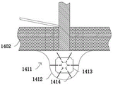
FIG. 14 is a schematic view of a mud throwing mechanism;
FIG. 15 is a schematic view of a lateral sludge reversing mechanism of the transduction tank;
FIG. 16 is a schematic illustration of a mud flap;
FIG. 17 is a side view of an aerobic tank plant growing module;
FIG. 18 is a schematic view of a mud collection module;
FIG. 19 is a schematic representation of a mud flap;
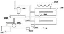
FIG. 20 is a schematic view of a sludge primary fermentation mechanism;
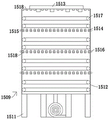
FIG. 21 is a schematic view of a sludge fermentation tank;
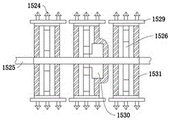
FIG. 22 is a schematic view of an exhaust gas collection module and an oxygen delivery module;
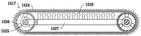
FIG. 23 is a front view of a sludge fermentation agitator;
FIG. 24 is a schematic view of a stirring rotating shaft;
FIG. 25 is a schematic view of a stirred oxygen mixing tube;
FIG. 26 is a front view of the canopy;
FIG. 27 is a schematic view of a planting frame;
FIG. 28 is a schematic view showing the transfer mechanism;
FIG. 29 is a top view of the planting rack;
FIG. 30 is a schematic view of a sludge coating mechanism;
FIG. 31 is a schematic view of a vegetation cleaning mechanism;
FIG. 32 is a schematic view of a fly rearing module;
FIG. 33 is a schematic view of a feeding substrate;
FIG. 34 is a schematic view of a sludge disinfection mechanism.
In the figure: greenhouse gas collector 1, methane collecting pad 101, secondary gas pipe 102, primary gas pipe 103, vent pipe 104, methane permeable membrane 105, permeable membrane 106, tertiary gas pipe 107, gas collecting membrane 108, heating module 109, ultrasonic module 2, dosing module 3, medicine tank 301, dosing pipeline 302, primary mixing tank 4, secondary mixing tank 5, energy conversion tank 6, heat exchange pipe 601, stirring module 7, fixed cross bar 701, stirring motor 702, stirring blade 703, stirring shaft 704, medicine releasing hole 705, sludge turning mechanism 8, turning motor 801, active roller 802, sludge turning belt 803, auxiliary roller 804, sludge removing groove 805, plant planting module 9, sludge collecting motor 901, sludge collecting module 902, rolling shaft 903, sludge collecting belt 904, sludge baffle 905, telescopic spring 906, support rod 907, sludge moving plate 908, side baffle 909, scraper 910, plant terrace 911, plant growing platform, and water, The greenhouse comprises a greenhouse body 10, a sunlight collector 1001, a solar cell panel 1002, a planting frame 1003, a support 1004, a conveying mechanism 1005, a plant planting belt 1006, a sludge storage tank 1007, a plant seed sowing module 1008, a sludge leveling roller 1009, a plough 1010, a plant cleaning mechanism 1011, a side suspension type plant cleaning module 1012, a plant collecting and cleaning box 1013, a sludge transmission module 1014, a sludge vibrating screen 1015, a barrel 11, a servo motor 1101, an air pipe 1102, a feeding port 1103, a rotating shaft 1104, a feeding base plate 1105, a water replenishing pipe 1106, a shell 12, a feeding port 1201, an ultraviolet ray module 1202, a squeezing motor 1203, a squeezing roller 1204, a sludge scraping plate 1205, an anoxic tank cover 13, a side plate 1301, an air guide cover 1302, an air collecting cover 1303, a maintenance cover 1304, a support column 1305, a mud discharging mechanism 14, a support 1402, a mud discharging belt, a mud collecting plate 1404, a limit plate 1405, a mud collecting plate support 1406, a lifting rod 1407, a water discharging rod 1408, a lifting spring 1409, The device comprises a hydrophobic rod temporary storage cavity 1410, a mud throwing mechanism 1411, a mud falling groove 1412, a mud throwing motor 1413, a mud throwing plate 1414, a primary sludge fermentation mechanism 15, a spiral conveying mechanism 1501, an auxiliary material conveying belt 1502, an auxiliary material storage bin 1503, a sludge crushing module 1504, a mixing module 1505, a sludge vertical lifting module 1506, a screening mechanism 1507, a sludge conveying belt 1508, a gravity type sludge fermentation mechanism 1509, an exhaust gas collection module 1510, a grid support 1511, a sludge fermentation bin 1512 and a sludge feeding pipeline 1513, an oxygen conveying module 1514, an oxygen conveying pipe 1515, an exhaust gas pipe 1516, a sludge fermentation stirrer 1517, an exhaust gas collecting module 1518, an odor collecting pipe 1519, an odor hole 1520, an oxygen feeder 1521, a top plate 1522, an oxygen outlet 1523, stirring crushing teeth 1524, a stirring rotating shaft 1525, a planetary gear set 1526, a stirring oxygen mixing pipe 1527, an oxygen mixer 1528, a stirring belt 1529, a stirring coaxial reversing mechanism 1530, a planetary gear protective sleeve 1531 and a pneumatic expansion plate 1532.
Detailed Description
In order to make the objects, technical solutions and advantages of the present invention more apparent, the present invention is further described in detail below with reference to examples and accompanying drawings, and the exemplary embodiments and descriptions thereof are only used for explaining the present invention and are not meant to limit the present invention.
Example one
The system comprises a sewage treatment module, a sludge treatment module and a control module which are connected through pipelines, wherein the sewage treatment module comprises a grid channel, a filter tank, an adjusting tank, a coagulating sedimentation tank and a tank A which are communicated with each other 2 A/0 pool, a combustion tank and an MBR membrane pool, wherein the sludge treatment module comprises a concentration pool, a high-temperature composting mechanism, a biological fertility increasing shed and a biological protein treatment module which are connected, A 2 A greenhouse gas collector 1 and a sludge discharge mechanism 14 are arranged on the anoxic pond of the/0 pond 2 Anoxic tank and aerobic tank of/0 tankThe oxygen pool is provided with an ultrasonic module 2; the high-temperature composting mechanism comprises a sludge primary fermentation module, a sludge secondary fermentation module and a vinasse feed module, and a planting greenhouse connected through a pipeline is arranged between the sludge primary fermentation module and the biological fattening greenhouse.
At least one group of coarse grids and fine grids which are equally spaced are arranged in the grid channel; an active carbon module is arranged in the filter tank; a sensor module connected with the control module is arranged in the regulating tank; the sensor module comprises a temperature sensor, a PH sensor and a water level sensor A 2 The/0 pool comprises an anoxic pool, an aerobic pool, an anoxic pool and a sedimentation pool which are communicated in sequence, A 2 The/0 pool is provided with a greenhouse gas collector 1, a dosing module 3 and an ultrasonic module 2 which are connected with the control module.
A primary mixing tank 4, a secondary mixing tank 5 and an energy conversion tank 6 which are formed by dividing the anoxic tank by a vertical baffle are arranged in the anoxic tank, and an anoxic tank cover 13 is arranged on the anoxic tank; the anoxic tank cover 13 comprises a side plate 1301 surrounding the anoxic tank, an air guide cover 1302 arranged on the side plate 1301 and covering the primary mixing tank 4 and the secondary mixing tank 5, supporting columns 1305 with different lengths are arranged between the air guide cover 1302 and different baffles, so that the air guide cover is inclined, the inclination angle is 10-20 degrees, a hemispherical air gathering cover 1303 arranged on the side plate 1301 and used for shielding the transduction tank 6, a flat maintenance cover 1304 is arranged between the air gathering covers 1303, and the air guide cover 1302, the air gathering cover 1303 and the maintenance cover 1304 are integrally connected with the side plate 1301; the greenhouse gas collector 1 comprises a pool outer part arranged on the outer side surface of the anoxic pool and a pool inner part arranged in a gas gathering cover 1303, the pool outer part comprises a negative pressure fan, a gas collecting tank and a processing module, the pool inner part comprises a water lower part, a water surface part and a water upper part, the water lower part comprises a plurality of vent pipes 104 communicated with the water surface part, the vent pipes 104 comprise methane vent films 105, the methane vent films 105 are sleeved with permeable films 106, and three-stage gas conveying pipes 107 communicated with the water surface part are arranged in the methane vent films 105; the surface of water portion has the square methane of numerous miniature gas pocket to collect pad 101 including inside, and methane is collected and is equipped with the water barrier with the surface of water contact on pad 101, and the water barrier is connected with the integration of portion under water, is equipped with a plurality of second grade gas-supply pipes 102 that are linked together with tertiary gas-supply pipe 107 in the methane collection pad 101, and second grade gas-supply pipe 102 is communicated with the air through micro air holes, a first-stage air conveying pipe 103 communicated with a second-stage air conveying pipe 102 and communicated with the water surface is arranged on the methane collecting pad 101, and the first-stage air conveying pipe 103 is communicated with the outside of the pool; the water upper part comprises a spherical gas collecting film 108 matched with the gas gathering cover 1303 through suspension wires, the distance between the spherical gas collecting film 108 and the gas gathering cover 1303 is 2-3mm, the gas collecting film 108 comprises a plurality of micro-tube gas permeable film layers 110 with a distance of 1-2mm, each micro-tube gas permeable film layer 110 comprises a plurality of gas permeable micro-tubes arranged along a hemispherical surface in a single layer, and a heating module 109 is arranged at the communication part of the gas collecting film 108 and the primary gas transmission pipe 103; heat exchange tubes 601 with the longitudinal interval of 50-80cm are arranged in the energy conversion pool 6; a sludge upper-reverse mechanism 8 is arranged between the heat exchange pipes 601, the sludge upper-reverse mechanism 8 comprises a turning motor 801 arranged on the outer side surface of the energy conversion pool 6, the turning motor 801 is connected with a driving roller 802 arranged on the upper part in the energy conversion pool through a coupler, three sludge turning belts 803 are meshed on the driving roller 802, a hollowed sludge pulling groove 805 is arranged on each sludge turning belt 803, the sludge upper-reverse mechanism further comprises two auxiliary rollers 804 in rolling fit with the sludge turning belts 803, and the auxiliary rollers 804 are arranged at the bottom of the energy conversion pool 6 and are symmetrically arranged along the central line of the driving roller 802; coaxial reversing devices are arranged in the middle of the driving roller 802 and the two auxiliary rollers 804, the mud turning belts 803 on the two sides of the driving roller 802 and the two auxiliary rollers 804 have the same rotation direction, and the rotation direction of the mud turning belts 803 in the middle of the driving roller 802 and the two auxiliary rollers 804 is opposite; the greenhouse gas collector 1 is communicated with a combustion tank, the combustion tank is communicated with the planting greenhouse, A 2 And a gas collection reverse hanging film is arranged on the anaerobic tank of the/0 tank.
The combustion tank comprises an outer layer tank body and an inner layer tank body, at least one square pipe reinforcing rib is arranged in the inner layer tank body, a cooling pipe connected with the energy conversion pool 6 is arranged between the outer layer tank body and the inner layer tank body, a boiler is arranged on the inner layer tank body, the boiler is communicated with the high-temperature composting mechanism and the biological fattening shed through a heating pipe, and an exhaust pipe on the inner layer tank body is communicated with the planting greenhouse;
the greenhouse gas collector 1 is provided with a dosing module 3 outside the tank, the dosing module 3 comprises a medicine tank 301, the medicine tank 301 is provided with a dosing pipeline 302 communicated with the anoxic tank, the primary mixing tank and the secondary mixing tank are provided with stirring modules 7 matched with the dosing pipeline, the stirring modules 7 comprise stirring motors 702 arranged on an air guide cover 1302, the greenhouse gas collector also comprises fixed cross rods 701 arranged in the primary mixing tank and the secondary mixing tank, the fixed cross rods 701 are provided with stirring shafts 704 meshed with the stirring motors 702, the stirring shafts 704 are provided with double-spiral stirring blades 703 and stirring auxiliary blades, the stirring auxiliary blades are distributed on the stirring shafts 704 along spiral lines and are vertical to the stirring shafts 704, the stirring directions of the stirring auxiliary blades are vertical to the spiral directions of the stirring blades, the stirring shafts 704 are hollow and communicated with the dosing pipeline 302, the stirring auxiliary blades and the stirring blades 703 are hollow and communicated with the stirring shafts 704, the side surface of the stirring auxiliary blade is provided with an ultrasonic module 2, and the stirring shaft, the stirring blade and the stirring auxiliary blade are provided with medicine releasing holes.
A sludge discharge mechanism 14 is arranged in the primary mixing tank 4 and the secondary mixing tank 5, and the sludge discharge mechanism 14 is arranged on the inner bottom surface of the primary mixing tank 4 and surrounds the inner side surface of the primary mixing tank 4 for a circle; the sludge discharge mechanism 14 comprises a concave surface-shaped mesh support 1402 fixed with the inner wall of the primary mixing pool, an auxiliary wheel is arranged on the support 1402, a sludge discharge belt 1403 matched with the auxiliary wheel in a rolling way is arranged on the concave surface of the support 1402, two side surfaces of the support 1402 are provided with limiting plates 1405 matched with the sludge discharge belt 1403 in a sliding way, sludge collection plates 1404 perpendicular to the sludge discharge belt 1403 are arranged on the sludge discharge belt 1403 at equal intervals, each sludge collection plate 1404 comprises a sludge collection plate support 1406 connected with the corresponding limiting plate 1405, an inner sleeve barrel with a hollow structure is arranged in each sludge collection plate support 1406, a lifting rod 1407 is arranged at the end, far away from the limiting plate 1405, in the inner sleeve barrel, a lifting spring 1409 connected with the limiting plate 1405 is arranged on the lifting rod 1407, the lifting spring 1409 is always in a compressed state, at least one arc-shaped water draining rod 1408 is arranged in an inverted U-shaped gap between the inner sleeve barrel and the mud collecting plate bracket 1406, a plurality of water draining rods 1408 are arranged along the U-shaped gap to form a mud collecting plate panel, and the water draining rod 1408 at the top of the inverted U-shaped gap is fixedly connected with the lifting rod 1407; a drainage rod temporary storage cavity 1410 matched with the inverted U-shaped gap is arranged on the sludge discharge belt 1403, a sliding groove for controlling the position of the lifting rod 1407 is arranged on the front side wall in the primary mixing tank 4, grooves are formed in the middle of supports 1402 at three included angles in the primary mixing tank 4, a power mechanism 1401 matched with the sludge discharge belt 1403 is arranged in the area between the outer side surface of the supports 1402 at the three included angles in the primary mixing tank 4 and the inner wall surface of the primary mixing tank 4, and the power mechanism 1401 adopts a closed magnetic non-contact transmission mechanism; the sludge discharge mechanism 14 further comprises a sludge throwing mechanism 1411 arranged at the included angle between the front side wall in the primary mixing tank 4 and the baffle, the sludge throwing mechanism 1411 comprises sludge falling grooves 1412 symmetrically arranged along the baffle, a sludge throwing motor 1413 is arranged on the side surface of each sludge falling groove 1412, a rotating shaft connected with the sludge throwing motor 1413 through a coupler is arranged in each sludge falling groove 1412, and a telescopic sludge throwing plate 1414 is arranged on each rotating shaft; and a power mechanism 1401 is arranged at the supports 1402 at two corners on the rear side wall in the secondary mixing pool 5.
In one embodiment, sewage produced in the white spirit production process is treated and filtered by a coarse grid and a fine grid in a grid channel, then particulate matters in the sewage are filtered, then the sewage enters a filtering tank for filtering, then organic matters in the filtered matters are sent to a vinasse feed mechanism to be stirred and fermented with vinasse, the filtered sewage enters an adjusting tank, the sewage in the adjusting tank is adjusted by a dosing barrel, the adjusted sewage enters a coagulating sedimentation tank, a coagulant is added and stirred, sludge is flocculated and precipitated, and the produced sludge is sent to a concentration tank;
the upper layer sewage enters A 2 The anaerobic tank in the/0 tank is used for anaerobic treatment, waste gas generated in the anaerobic stage is collected through a gas-collecting reverse hanging membrane and then sent into a biological treatment module to carry out microbial treatment on nitrogen-containing gas and sulfide in the waste gas, then the treated sewage is sent into an anoxic tank, the Hydraulic Retention Time (HRT) in the anoxic tank is 24H-36H, the preferred hydraulic retention time is 24H, the PH value is maintained between 6.5 and 7.5, the preferred PH value is 7.3, the temperature is 20-40 ℃, the preferred water temperature is 30 ℃, the sewage firstly enters the primary mixing tank 4, the sewage overflows a baffle plate after filling the primary mixing tank 4 and enters the secondary mixing tank 5, the control module controls a medicine tank 301 to send a regulating reagent into a stirring shaft 704, stirring blades 703 and stirring auxiliary blades through a medicine adding pipeline 302 arranged in a stirring mechanism 7, the sewage is fed into sewage through a stirring shaft 704, a stirring blade 703 and a medicine releasing hole in an auxiliary stirring blade, the stirring blade 703 has a double-helix structure, and the stirring blade 703 generates two-direction moments on a water body, so that the water bodies in different layers are extruded, intersected and collided at the stirring blade 703, the medicine is quickly blended into the water body, and the auxiliary stirring blade generates two-direction moments on the water body while the stirring blade 703 stirsThe water body on the stirring auxiliary blade is far away from the stirring shaft 704 due to the transverse moment, and negative pressure is formed after the water body near the stirring shaft 704 is far away from the stirring shaft 704, so that the water body on the other side of the stirring auxiliary blade is close to the vicinity of the stirring shaft 704 and is rapidly mixed with the medicine under the action of the stirring blade 703;
meanwhile, as the stirring auxiliary blade pushes one side of the water body to be the ultrasonic module 2, the ultrasonic module 2 works at low intensity while pushing the water body to stir, the working power of the ultrasonic module 2 is 8-12W, preferably 11W, sewage and sludge are treated according to the frequency of 20-100kHz, and low-intensity irradiation is carried out on the water body, as the ultrasonic wave can thin the cell membrane and the cell wall of anaerobic bacteria, the cell metabolism is enhanced, the cell activity is enhanced, meanwhile, the steady-state cavitation effect can cause damage to the cells, the release of enzyme is increased during self-repair of the cells, the micro bubbles of the ultrasonic wave enhance the action of the enzyme, the activity of the enzyme is improved, and the denitrification reaction rate is accelerated;
greenhouse gases generated in the anoxic stage are collected through the greenhouse gas collector 1, the interior of the greenhouse gas collector 1 is in a negative pressure state through a negative pressure fan outside the greenhouse gas collector, the length of the permeable pipe 104 at the lower part of the water is longer at the position close to the baffle plate and the right side wall surface, the water body enters the area between the permeable film 106 and the methane permeable film 105 under the action of the permeable film 106 of the permeable pipe 104, most of dirt in the water body is blocked at the outer side of the permeable film 106, methane and gases smaller than methane molecules enter the tertiary gas conveying pipe 107 through the methane permeable film 105, the gases enter the secondary gas conveying pipe 102 in the water surface part along the tertiary gas conveying pipe 107, meanwhile, the gases in the anoxic tank cover 13 enter the secondary gas conveying pipe 102 through the micro air holes on the methane collecting cushion 101, the gases entering the secondary gas conveying pipe 102 enter the gas collecting tank through the primary gas conveying pipe 103, and the gases in the gas collecting cover 1303 enter the primary gas conveying pipe 103 through the gas collecting film 108 at the upper part of the water conveying pipe, when the negative pressure fan is not started, the gas in the primary gas transmission pipe 103 can be heated by the heating module 109 on the water upper part, the heated gas in the primary gas transmission pipe 103 flows along the outer part of the primary gas transmission pipe 103 pool, the pressure of the primary gas transmission pipe 103 is lower, pressure difference is formed between the water lower part and the water surface part and the primary gas transmission pipe 103, and the gas is collected by the pressure difference;
in order to accelerate the gas production rate, cooling liquid is sent into a heat exchange pipe 601 in the energy conversion pool 6 through a cooling pipe of a combustion tank, the cooling liquid is used for maintaining the temperature of sewage and providing proper temperature for anaerobic reaction, then a stirring motor 801 drives a driving roller 802 to rotate and further drives a mud stirring belt 803 meshed with the driving roller to move, the mud stirring belt 803 drives a mud stirring groove 805 to stir the mud at the bottom upwards, the mud stirring belt 803 in the middle downwards rotates under the action of a coaxial reversing device 806 to stir the sewage at the upper part downwards, the methane generated by the sludge at the lower part is more easily stirred to the upper part, meanwhile, the contact area and the contact duration of anaerobic bacteria and organic matters in the sewage sludge are increased, and the denitrification effect is improved;
after the anoxic tank is used for a long time, sludge accumulation is easily generated at the joint of the inner side wall and the bottom surface in the primary mixing tank 4 and the secondary mixing tank 5, toxins are easily generated after long-time non-cleaning, the anoxic environment is damaged, when sludge needs to be cleaned, the power mechanism 1401 drives the sludge discharge belt 1403 meshed with the power mechanism to move on the support 1402, the sludge discharge belt 1403 drives sludge between the sludge collecting plates 1405 to move, when the sludge moves to the front side wall in the primary mixing tank 4 and the secondary mixing tank 5, the chute on the front side wall is gradually close to the bottom surface towards the baffle direction, meanwhile, both ends of the water conveying rod 1408 do not always enter the inverted U-shaped gap of the sludge collecting plate support 1406, the lifting rod 1407 in the chute approaches to the limiting plate 1405 from the upper end of the sludge collecting plate support 1406, and then pushes the water conveying rod 1408 to enter the water conveying rod temporary storage cavity 1410, so that the height of the sludge collecting plates 1405 is continuously reduced, and then the sludge is better placed into the sludge dropping groove 1412 of the sludge throwing mechanism 1411, the mud throwing motor 1413 works to drive the mud throwing plate 1414 to rotate, when the mud throwing plate 1414 moves into the semicircular mud falling groove 1412, the mud throwing plate 1414 extends to throw the sludge from the primary mixing tank 4 into the secondary mixing tank 5 and then is taken away by the mud discharging mechanism 14 in the secondary mixing tank 5, and the mud discharging mechanism 14 in the secondary mixing tank 5 conveys the sludge into the energy conversion tank 6 to prevent the sludge from being accumulated in the primary mixing tank 4 and the secondary mixing tank 5.
As shown in fig. 17-19, ultrasonic modules 2 are arranged on both sides of the aerobic tank, a dosing module 3 is arranged on the aerobic tank, and activated carbon adsorption modules are arranged in the aerobic tank and the MBR membrane tank; the aerobic tank is provided with a plant planting module 9; the plant planting module 9 comprises a sludge collecting motor 901 arranged outside the aerobic tank, and further comprises a floating mud collecting module 902 connected with the sludge collecting motor 901, the floating mud collecting module 902 comprises two rolling shafts 903 arranged in the aerobic tank in parallel, a floating mud collecting belt 904 is tensioned on the two rolling shafts 903, floating mud baffles 905 are arranged on the outer side surfaces of the floating mud collecting belt 904 at equal intervals, the floating mud baffles 905 are rectangular, a supporting rod 907 fixed with the floating mud collecting belt 904 is arranged on one side of each floating mud baffle 905, the supporting rod 907 enables the included angle between the floating mud baffle 905 and the floating mud collecting belt 904 to be 30-50 degrees, side baffles 909 are arranged on the two side surfaces of each floating mud baffle 905, a floating mud movable plate hinged with the supporting rod 907 is arranged between the two side baffles 909, and telescopic springs 906 connected with the floating mud baffles 905 are arranged on the two side surfaces of the floating mud movable plate 908; the plant planting module 9 further comprises a plant planting terrace 911 arranged on the aerobic tank, and a scraper 910 matched with the floating mud baffle 905 is arranged on the plant planting terrace 911.
In one embodiment, the sewage treated in the anaerobic tank enters A 2 In an aerobic pool in the/0 pool, the Hydraulic Retention Time (HRT) in the aerobic pool is 2H-8H, preferably 6H, the PH value is maintained between 3-5, preferably 3.5, the temperature is 20-40 ℃, preferably the water temperature is 25 ℃, sewage firstly enters the primary mixing pool 4, the sewage overflows the baffle plate and enters the secondary mixing pool 5 after filling the primary mixing pool 4, the control module controls the medicine tank 301 to send hydrogen peroxide into the aerobic pool through the medicine adding pipeline 302 arranged in the stirring shaft 704 of the stirring mechanism 7 in the aerobic pool, and finally the hydrogen peroxide is sent into the sewage through the medicine releasing hole 705 on the stirring shaft 704, meanwhile, the stirring motor 702 drives the stirring shaft 704 to rotate so as to drive the stirring blade 703 to stir the sewage, the hydrogen peroxide is catalytically decomposed to generate OH, and the oxidation of reducing substances is accelerated;
when the sewage is treated in the aerobic tank, plants capable of absorbing heavy metals can be planted on the surface of the aerobic tank through the plant planting module 9 when the sewage contains more heavy metals, the sludge collecting motor 901 drives the rolling shaft 903 of the floating sludge collecting module 902 to rotate, the rolling shaft 903 drives the floating sludge collecting belt 904 to rotate, and then the floating sludge baffle 905 is driven to rotate, when the floating sludge baffle 905 moves to the position of the scraping plate 910, the scraping plate 910 is fixedly connected with the plant planting terrace 911 through four telescopic rods positioned at the corners, the included angle between the scraping plate 910 and the floating sludge collecting belt 904 is the same as the inclination angle of the floating sludge baffle 905, the scraping plate 910 pushes the sludge onto the floating sludge movable plate 908, along with the movement of the floating sludge collecting belt 904, the force received by the floating sludge movable plate 908 is gradually increased and then the telescopic spring 906 is stressed to be lengthened, the included angle between the floating sludge movable plate 908 and the floating sludge baffle 905 is gradually increased until the telescopic spring 906 extends to the longest, at the moment, the included angle between the floating mud movable plate 908 and the floating mud collecting belt 904 is 45-60 degrees, then the floating mud movable plate 908 is released from being limited to be restored under the action of the telescopic spring after passing through the scraper plate 910, the mud on the scraper plate 910 moves onto the plant lawn 911 under the action of inertia, the floating mud in the aerobic pool is collected onto the plant lawn 911 in a circulating mode for multiple times in sequence, a dosing pipeline 302 and a PH sensor which are communicated with the dosing module 3 are arranged on the plant lawn 911, the PH value on the plant lawn 911 is adjusted through the dosing device 3, and then plants which absorb heavy metals absorb a part of heavy metals in the sewage are planted;
after the sewage aeration treatment in the aerobic tank is finished, the PH of the sewage is adjusted to PH =5 through the dosing module 3, the activated carbon is arranged at the water outlet of the aerobic tank, and the SMP (symmetric multi-processing) part in the sewage is adsorbed through the activated carbon, so that the SMP content in the sewage is reduced.
As shown in fig. 2 and fig. 20-31, the outer side surface of the sludge primary fermentation mechanism 15 is provided with an ultrasonic module, and the sludge secondary fermentation mechanism and the vinasse feed module are communicated with a biological fertility increasing shed; the biological weight-gaining shed comprises a fly raising module and a fly separating module which are communicated with each other, and also comprises an earthworm raising module, an earthworm separating module and a sludge disinfecting mechanism which are communicated with each other, wherein a sludge secondary fermentation mechanism is arranged between the earthworm raising module and the fly separating module; the fly and worm separation module and the earthworm separation module are connected with a protein processing module connected with the control module, the primary sludge fermentation mechanism 15 comprises a spiral conveying mechanism 1501 communicated with the concentration tank, a sludge crushing module 1504 is arranged at the discharge end of the spiral conveying mechanism 1501, a sludge conveying belt 1508 is arranged at the discharge port of the sludge crushing module 1504, the primary sludge fermentation mechanism further comprises an auxiliary material conveying belt 1502, an auxiliary material storage bin 1503 is arranged at the discharge end of the auxiliary material conveying belt 1502 and connected with a sludge conveying belt 1508 at the discharge port of the sludge crushing module 1504 through the auxiliary material conveying belt 1502, a material mixing module 1505 is arranged at the discharge end of the sludge conveying belt 1503, the discharge end of the material mixing module 1505 is connected with a gravity type sludge fermentation mechanism 1509 through the sludge conveying belt 1508, a sludge vertical lifting module 1508 connected with the sludge conveying belt is arranged on the gravity type sludge fermentation mechanism 1509, an air pump and a waste gas collecting and processing module 1510 are arranged on the gravity type sludge fermentation mechanism 1509, gravity type sludge fermentation mechanism 1509 discharge end is connected with screening mechanism 1507 through mud conveyer belt 1508, and screening mechanism 1507 lower floor's discharge gate is connected with the planting big-arch shelter, and screening mechanism 1507 upper discharge gate is connected with compounding module 1505, is equipped with PH sensor and PH regulation dosing tank on the concentrated pond, and the first fermentation mechanism lateral surface of mud is equipped with the ultrasonic wave module.
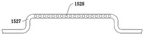
The gravity type sludge fermentation mechanism 1509 comprises a grid support 1511, a sludge fermentation bin 1512 is arranged on the grid support 1511, a waste gas pipe 1516 communicated with the waste gas collecting and processing module 1510 is arranged on the outer side surface of the sludge fermentation bin 1512, an oxygen conveying pipe 1515 communicated with an air pump is further arranged on the outer side surface of the sludge fermentation bin 1512, a sludge feeding pipeline 1513 connected with the vertical lifting module 1506 is arranged at the top of the sludge fermentation bin 1512, and a sludge conveying pipe communicated with the sludge fermentation bin 1512 is arranged on the sludge feeding pipeline 1513; four layers of fermentation chambers are arranged in the sludge fermentation bin 1512, a waste gas collecting module 1518 communicated with a waste gas pipe 1516 is arranged at the top of the fermentation chamber of the fourth layer, the waste gas collecting module 1518 comprises a strip-shaped odor collecting pipe 1519 with a hollow structure, and an odor hole 1520 communicated with the fermentation chamber is arranged on the odor collecting pipe 1519; an oxygen delivery module 1514 communicated with an oxygen delivery pipe 1515 is arranged on the waste gas collection module 1518 of the first layer, the second layer and the third layer of fermentation chambers, the oxygen delivery module 1514 comprises a pneumatic telescopic plate 1532 arranged on the waste gas collection module 1518, the pneumatic telescopic plate 1532 is connected with a gas compressor through a pipeline, a hollow oxygen feeder 1521 communicated with the oxygen delivery pipe is arranged on the pneumatic telescopic plate 1532, the oxygen feeder 1521 comprises two parallel side wall plates, a semicircular top plate 1522 is arranged on each side wall plate, the distance between the side wall plates is smaller than the diameter 1-2cm of the top plate 1522, an oxygen outlet hole 1523 is arranged at the part, exceeding the side wall plate, of the top plate 1522, close to the end of the side wall plate, and the oxygen outlet hole 1523 is communicated with the oxygen delivery pipe 1515 through the hollow oxygen feeder 1521; a sludge fermentation stirrer 1517 communicated with the oxygen conveying pipe 1515 is further arranged in the fermentation chamber, the sludge fermentation stirrer 1517 comprises a fermentation stirring motor arranged on the outer side surface of the sludge fermentation chamber 1512, and further comprises a stirring rotating shaft 1525 arranged in the fermentation chamber and connected with the fermentation stirring motor through a coupler, three planetary gear sets 1526 are arranged on the stirring rotating shaft 1525 along the axis, the transmission ratios of the three planetary gear sets 1526 are different, a planetary gear protecting sleeve 1531 matched with the planetary gear set 1526 is arranged on the stirring rotating shaft 1525, a stirring coaxial reversing mechanism 1530 is arranged in the planetary gear protecting sleeve 1531 in the upper middle of the stirring rotating shaft 1525, a stirring belt driving wheel is arranged on the outer side surface of the planetary gear set 1526, a stirring belt 1529 is meshed on the outer side surface of the stirring belt driving wheel, sludge gaps convenient for sludge particles to pass through are arranged on the stirring belt 1529, plow-shaped stirring crushing teeth 1524 are arranged on the stirring belt 9, a stirring oxygen mixing pipe 1527 communicated with the oxygen conveying pipe 1515 is arranged between the stirring belts 1529, an umbrella-shaped oxygen mixer 1528 is arranged on the stirring oxygen mixing pipe 1527.
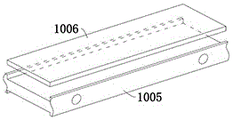
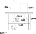
The planting greenhouse comprises a greenhouse body 10, wherein slopes with an inclination angle of 20-50 degrees are arranged at the top of the greenhouse body 10, solar panels 1002 are arranged on the slopes, arc-shaped transparent roofs are arranged between the slopes, and a sunlight guiding system is arranged on the greenhouse body 10; the sunlight guide-in system comprises a sunlight collector 1001 arranged on the roof of the shed, and also comprises an optical cable and a lamp which are arranged in the shed body, wherein the lamp comprises an LED lamp and a solar lamp; a storage battery connected with the solar cell panel 1002 is arranged in the shed body 10, the storage battery is connected with a lamp, and a spiral planting frame 1003 is also arranged in the shed body 10; the planting frame 1003 comprises a support 1004, a conveying mechanism 1005 is arranged on the support 1004, the inclination angle of the conveying mechanism 1005 to the ground is 5-15 degrees, the distance between the conveying mechanisms 1005 is 20-50cm, the conveying mechanism 1005 spirally rises from the innermost circle of the planting frame 1003, then spirally descends in the second circle, spirally rises in the third circle, and spirally descends to the lowest in the outermost circle to be out of the shed body 10; the upper part of the conveying mechanism 1005 is provided with a plant growing belt 1006, the lower end face of the conveying mechanism 1005 is provided with a lamp, a carbon dioxide discharge pipe, a temperature and humidity sensor, a water dropping pipe and a carbon dioxide concentration sensor, the carbon dioxide discharge pipe is communicated with the combustion tank, and the water dropping pipe is communicated with the MBR membrane tank; a sludge coating mechanism 1006 positioned in the middle of the spiral planting frame 1003 is further arranged in the greenhouse body, the sludge coating mechanism 1006 comprises a mounting seat matched with the conveying mechanism 1005, a sludge storage tank 1007 communicated with a sludge conveying pipeline is arranged on the mounting seat, a plant seed sowing module 1008 matched with the sludge storage tank 1007 is further arranged on the mounting seat, a microorganism placing module is arranged on the sowing module 1008, and a sludge discharging pipe and a sowing pipe matched with the conveying mechanism 1005 are arranged on the sludge storage tank 1007 and the plant seed sowing module 1008; a sludge leveling roller 1009 and a plough 1010 which are in sliding fit with the transmission mechanism 1005 are arranged between the sludge discharging pipe and the seeding pipe, and a sludge leveling roller 1009 is arranged on one side of the seeding pipe.
A plant cleaning mechanism 1011 matched with the tail end of the plant frame 1003 is arranged in the shed body, the plant cleaning mechanism 1011 comprises a side-hung plant cleaning module 1012 in sliding fit with the conveying mechanism 1005, a plant collecting and cleaning box 1013 fixed with the ground is arranged on the side-hung plant cleaning module 1012, a cleaning mechanism is arranged in the plant collecting and cleaning box 1013 and comprises a high-pressure nozzle, and a sewage backflow module communicated with a concentration tank is arranged below the high-pressure nozzle; a sludge transmission module 1014 is arranged below the conveying mechanism 1005, and a sludge vibrating screen 1015 which is used for screening out impurities and communicated with the sludge transmission module 1014 is arranged on the sludge transmission module.
In one embodiment, the sludge is concentrated and then sent into the primary sludge fermentation mechanism 15, supernatant liquid flows back to the regulating reservoir for continuous treatment, the sludge is sent into the sludge crushing module 1504 through the screw conveying mechanism 1501 of the primary sludge fermentation mechanism 15 for crushing, then useless organic matters (dead branches and fallen leaves, sawdust and the like) in a winery are treated and then sent into the auxiliary material storage bin 1503 through the auxiliary material conveying belt 1502, then sent onto the sludge conveying belt 1508 between the sludge crushing module 1504 and the mixing module 1505 through the sludge conveying belt 1508, auxiliary materials and the crushed sludge are premixed, and then sent into the mixing module 1508 through the sludge conveying belt 1508;
the auxiliary materials and the sludge are mixed by the mixing module 1508, the auxiliary material lumps after passing through the screening mechanism 1507 are conveyed into the mixing module 1508 to be mixed, the mixed sludge is conveyed into a sludge feeding pipeline 1513 of the gravity type sludge fermentation mechanism 1509 through the sludge conveying belt 1508 and the sludge vertical lifting device 1506 and then enters the sludge fermentation chamber 1512, the sludge firstly enters an uppermost layer (fourth layer) fermentation chamber of the sludge fermentation chamber 1512, at the moment, the pneumatic expansion plate 1532 is unfolded through the gas compressor to seal gaps between adjacent oxygen delivery modules 1514, the sludge cannot fall into a third layer fermentation chamber through gaps between the oxygen delivery modules 1514, a heat exchanger connected with a combustion tank is arranged in the inner wall of the sludge fermentation chamber 1512 and used for maintaining the temperature in the sludge fermentation chamber 1512, and the ultrasonic module 2 works to perform low-intensity irradiation on the sludge to promote the fermentation of the sludge;
the air pump works to send outside air into the oxygen delivery module 1514 through the oxygen delivery pipe 1515, the aerobic air enters the oxygen delivery device 1521, then the sludge is oxygenated from the bottom of the sludge through the oxygen outlet hole 1523, the top plate 1522 partially blocks the sludge which can better block the oxygen outlet hole 1523 beyond the side plate, and the sludge can drive the sludge fermentation stirrer 1517 to turn over the sludge at regular time in the fermentation process;
when one sludge fermentation stirrer 1517 is arranged longitudinally, the fermentation stirring motor drives the stirring rotating shaft 1525 to rotate through the shaft coupling, the sun gear on the stirring rotating shaft 1525 drives the three planetary gear sets 1526 to rotate, the stirring coaxial inversion mechanism 1530 is arranged on the middle planetary gear set, so that the rotating direction of the middle planetary gear set 1526 is opposite to the rotating direction of the planetary gear sets 1526 on the two sides, meanwhile, the transmission ratio of the middle planetary gear set 1526 to the planetary gear sets 1526 on the two sides is different, the linear speed of the stirring belt 1529 on the middle planetary gear set 1526 is different from the linear speed of the stirring belts 1529 on the planetary gear sets 1526 on the two sides, and when the middle stirring belt 1529 and the stirring belts 1529 on the two sides move relatively, a pressure difference 1529 is generated, so that the sludge is close to the middle stirring belt 1529, the sludge is prevented from being accumulated near the front and rear inner walls of the fermentation chamber, and a part of the left and right inner walls is accumulated, the plow-shaped stirring crushing teeth 1524 on the stirring belt 1529 can crush and stir the sludge well, gaps among sludge particles are enlarged to meet the oxygen demand of aerobic bacteria, then air is sent into the sludge in a stirring state through the oxygen mixer 1528 on the stirring oxygen mixing pipe 1527, and odor generated in the fermentation process is conveyed to the waste gas collecting and processing module 1510 through the waste gas collecting module 1518 to be subjected to biological deodorization processing;
when two sludge fermentation stirrers 1517 are arranged longitudinally, the stirring belts 1529 are arranged in parallel, fermentation stirring motors on the upper and lower layers of sludge fermentation stirrers 1517 rotate in the same direction in the sludge stirring process, sludge on the inner wall of the left side of the fermentation chamber is taken away by the lower layer of sludge fermentation stirrer 1517 when being carried and stacked by the upper layer of sludge fermentation stirrer 1517, so that the sludge on the inner walls of the left and right sides of the fermentation chamber is in dynamic balance, and the sludge can be redistributed when the upper layer or the lower layer stops working, thereby reducing sludge stacking;
when two sludge fermentation agitators 1517 are arranged, one is arranged longitudinally, the other is arranged transversely, the agitating belts 1529 are arranged in parallel, one sludge fermentation agitator 1517 is arranged above the other sludge fermentation agitator 1517 is arranged below the other sludge fermentation agitator 1517, when in work, the longitudinally arranged sludge fermentation agitator 1517 can transversely generate a pressure difference close to the agitating belts 1529 in the middle part, when in work, the transversely arranged sludge fermentation agitator 1517 can longitudinally generate a pressure difference close to the agitating belts 1529 in the middle part, so that the sludge on the inner wall of the fermentation chamber is close to the middle part, the accumulation of the sludge on the inner wall of the fermentation chamber is reduced,
when two sludge fermentation stirrers 1517 are provided, one is longitudinally arranged, the other is transversely arranged, the stirring belts 1529 are arranged in parallel, one sludge fermentation stirrer 1517 penetrates through the other sludge fermentation stirrer 1517, and the stirring belts 1529 can effectively turn over the sludge on the upper part and the lower part during movement, so that the air and the sludge can be mixed conveniently, and the sludge can be fully fermented;
after fermentation is finished in the fourth layer fermentation chamber, a gap between the adjacent oxygen delivery modules 1514 is opened by closing a pneumatic expansion plate 1532 through a gas compressor, then a sludge fermentation stirrer 1517 is started to drive sludge to move, the sludge enters the third layer fermentation chamber through the gap between the oxygen delivery modules 1514 under the action of gravity to be fermented again, the sludge circulates sequentially, the fermented sludge is conveyed into a screening mechanism 1507 through a sludge conveying belt 1508, and the fermented sludge enters a sludge conveying pipeline through a lower layer discharge hole of the screening mechanism 1507;
then the sludge is sent into a sludge storage tank 1007 of a planting greenhouse phase, a chemical adding module 3 for adjusting the pH of the sludge is arranged on the sludge storage tank 1007, a control module controls a driving motor on a transmission mechanism 1005 to drive the transmission mechanism 1005 to run at a constant speed, the sludge is coated on a plant planting belt 1006 of the transmission mechanism 1005 through a sludge blanking pipe, the sludge is uniformly coated on the plant planting belt 1006 under the action of a sludge leveling roller 1009 along with the movement of the transmission mechanism 1005, then the sludge on the plant planting belt 1006 is ploughed out of at least one planting groove under the action of a plough 1010, then plant seeds absorbing heavy metals are sown in the planting grooves through a plant seed sowing module 1008, then the planting grooves are wiped under the action of the sludge leveling roller 1009, the seeds are covered in the sludge, microorganisms promoting the absorption and the transfer of the heavy metals are scattered into the planting grooves through a microorganism putting module while the seeds are sown, such as arbuscular mycorrhizal fungi;
then the sowed sludge enters the spiral planting frame 1003 under the action of the conveying mechanism 1005, the innermost circle of the planting frame 1003 spirally rises, then spirally descends in the second circle, spirally rises in the third circle, and spirally descends to the lowest position to move to the plant cleaning mechanism 1011, because the planting frame 1003 is spiral and the conveying mechanism 1005 on the planting frame has multiple layers, the time from sowing to plant growing to moving to the plant cleaning mechanism 1011 needs 1-2 months, and at least two planting greenhouses are provided;
plant that plants on with mud is pulled up through side suspension plant clearance module 1012 of plant clearance mechanism 1011 and is sent into plant collection cleaning box 1013, wash the plant through wiper mechanism, sewage passes through the backward flow module and sends back in the concentrated pond, then carry out innocent treatment with the plant, mud drops to mud shale shaker 1015 carries out crushing treatment with mud, drop on mud transmission module 1014 through the space between the shale shaker, mud draws the sample and detects and observes wherein heavy metal content exceeds standard, if exceed standard then send back the mud bin 1007 to reprocess through mud transmission module 1014, if accord with the standard then send into the fly and raise the module.
As shown in fig. 32-34, the whole stillage feed module employs a whole stillage fermentation mechanism; the fly breeding module comprises a stirring part and a breeding part, wherein the stirring part comprises a feed stirring mechanism communicated with the vinasse fermentation mechanism and the planting greenhouse; the feeding part comprises a cylindrical barrel body 11, and the top of the barrel body is provided with a feeding port communicated with the feed stirring mechanism; a servo motor 1101 communicated with the control module is arranged at the upper part of the outer side surface of the barrel body 11, a rotating shaft 1104 matched with the servo motor 1101 is arranged in the barrel body 11, a spiral feeding substrate 1105 is arranged on the outer side surface of the rotating shaft 1104, a sludge baffle is arranged on the outer side surface of the feeding substrate 1105, an air pipe 1102 communicated with the outside and a water replenishing pipe 1106 communicated with the water outlet of the MBR membrane pool are arranged in the rotating shaft 1104, electromagnetic valves connected with the control module are arranged on the air pipe 1102 and the water replenishing pipe 1106, a net-shaped water replenishing sprayer communicated with the water replenishing pipe 1106 is arranged in the feeding substrate 1105, a heating module connected with the control module is also arranged, and a temperature and humidity sensor communicated with the control module is also arranged in the barrel body 11; the fly and insect separation module adopts a centrifugal separation mechanism; the earthworm breeding module and the earthworm separation module are of the same structure as the fly breeding module and the fly separation module; the sludge disinfection mechanism comprises a shell 12, a feed inlet 1201 communicated with the earthworm separation module is arranged on the shell 12, an ultraviolet module 1202 connected with the control module is arranged in the shell, and an extrusion module is arranged at an irradiation port of the ultraviolet module 1202; the extrusion module comprises an extrusion motor 1203 arranged on the outer side surface of the shell 12, an extrusion roller 1204 connected with the extrusion motor 1203, a sludge scraper 1205 in rolling fit with the extrusion roller 1204, a flat sludge channel is formed by gaps among the sludge scrapers, and the sludge disinfection mechanism further comprises an ultrasonic module 2 matched with the sludge channel.
Sludge disinfection mechanism includes the shell, is equipped with the feed inlet that is linked together with earthworm separation module on the shell, is equipped with the ultraviolet module that is connected with control module in the shell, is equipped with extrusion module in ultraviolet module's exposure department, including establishing the extrusion motor at the shell lateral surface, still includes the squeeze roll of being connected with extrusion motor, still includes the mud scraper blade with squeeze roll cooperation, and the space between the mud scraper blade constitutes the mud passageway of platykurtic
In one embodiment, the distillers 'grains fermented by the distillers' grains feed module and the sludge are stirred and mixed in the feed stirring mechanism, and then are fed into the barrel body 11 through the feed inlet 1103, and simultaneously fly is mixed into the sludge mixture, the servo motor 1101 drives the rotating shaft 1104 to rotate through the transmission chain, and then drives the feeding substrate 1105 to spiral downwards, the temperature and the humidity in the barrel body 11 are monitored through the temperature and humidity sensor, then the outside air is sterilized through the air pump communicated with the air pipe 1102 and then fed into the barrel body 11, so as to ensure the oxygen content in the barrel body 11, the water treated outside through the MBR membrane pool is fed into the barrel body 11 through the water pump communicated with the water replenishing pipe 1106, the radiating pipe communicated with the combustion tank is arranged in the barrel body 11, so as to ensure that the temperature in the barrel body 11 is proper, after the fly grows into adults, the sludge is separated from the fly adults through the centrifugal fly separating module, the adult insects are dried, crushed and sterilized through the protein processing module to prepare the poultry protein feed, the sludge is treated by the sludge secondary fermentation mechanism and then is fed into the earthworm breeding module for breeding, the sludge treated by the earthworms is effectively improved and can be used in agricultural production, and the adult earthworms are dried, crushed and disinfected by the protein treatment module to prepare poultry protein feed which can be sold to the poultry breeding plant to increase the income of the winery;
mud after earthworm separation module separation gets into in the extrusion module of shell 12 through feed inlet 1201 of mud disinfection mechanism, drive squeeze roll 1204 through extrusion motor 1203 and rotate, mud is close to and is extruded by squeeze roll 1204 to squeeze roll 1204 under the action of gravity and get into the mud passageway of platykurtic, mud passes through ultraviolet module 1202 high dose when passing through the mud passageway and shines and through passing through ultrasonic module high strength treatment, disinfect mud, can sell in agricultural production mechanisms such as farm through sterile mud, increase the winery income.
Example two
A comprehensive treatment method for liquor production wastewater comprises the following steps: (1) sewage generated in liquor production enters a filtering tank through a grid channel for filtering, then enters an adjusting tank for adjusting the pH of the sewage through a medicine tank, then enters a coagulating sedimentation tank for adding a coagulant to carry out sedimentation treatment on the sludge, and the sludge is sent into a concentration tank;
(2) the sewage treated in the coagulating sedimentation tank enters A 2 Treatment in the/0 tank with the ultrasonic module 2 to A 2 0, treating in an anaerobic pond, maintaining the Hydraulic Retention Time (HRT) in a range of 24H-36H, preferably 24H, the pH value in a range of 6.5-7.5, preferably 7.3, the temperature in a range of 20-40 ℃, preferably 30 ℃ of water, maintaining the Hydraulic Retention Time (HRT) in a range of 2H-8H, preferably 6H, the pH value in a range of 3-5, preferably 3.5, the temperature in a range of 20-40 ℃, preferably 25 ℃ of water, treating the sludge at a frequency of 20-100kHz, delivering the greenhouse gas generated in an anoxic pond into a combustion tank through a greenhouse gas collector 1, delivering the carbon dioxide generated by the combustion treatment into a planting greenhouse through heat exchange, absorbing and solidifying the carbon dioxide by plants, reducing greenhouse gas emission, feeding heat generated by combustion tanks into a high-temperature composting arrangement and A 2 The water in the/0 pool is used as supplementary energy and is fed to the A direction through the medicine adding module 3 2 Adding hydrogen peroxide and activated carbon into a pond to control the SMP content in the sewage;
(3) through A 2 The sewage treated in the/0 tank is sent into an MBR membrane tank for treatment, the SMP content in the MBR membrane tank is controlled by adding a certain amount of ibuprofen into the MBR membrane tank and controlling the Sludge Retention Time (SRT) and DO concentration, and the redundant sludge is sent into a concentration tank;
(4) the method comprises the following steps that supernatant liquid of sludge in a concentration tank is sent into a regulating tank after concentration, the sludge enters a sludge primary fermentation mechanism to be fermented, meanwhile, an ultrasonic module 2 irradiates for 35min at the working power of 8-12W, preferably 9W according to the frequency of 20-100kHz to treat the sludge, vinasse is sent into a vinasse feed mechanism to ferment the vinasse, waste gas generated in the fermentation process is sent into a combustion tank, the fermented sludge is sent into a planting greenhouse to absorb part of heavy metal in the sludge through absorption and transfer of plants, and the content of the heavy metal in the sludge, particularly chromium and lead, is reduced;
(5) stirring fermented vinasse and sludge by the sludge treated by the planting greenhouse through a stirring mechanism, then feeding the sludge into a fly raising module to carry out biological treatment on ova and microorganisms in the sludge by using flies, and feeding mature flies into a protein treatment module after the fly separation module is used for treating, dewatering and crushing the fly eggs and the microorganisms to prepare biological protein for raising poultry; the sludge is stirred together with fermented vinasse through the stirring mechanism after secondary fermentation and then is sent into the earthworm feeding module, the sludge texture is improved through earthworms, meanwhile, biological treatment is carried out on worm eggs and microorganisms in the sludge, the earthworms are separated out through the earthworm separating mechanism after the sludge is treated and then are sent into the protein treatment module to be made into poultry feed, and the separated sludge is irradiated and disinfected through the ultraviolet module 1202 in the sludge disinfecting mechanism to obtain the sludge capable of being used for fertilizing the field.
It should be noted that, for those skilled in the art, many changes and modifications can be made without departing from the spirit and scope of the invention, and the invention is not to be considered limited to the embodiments illustrated in the drawings.
Claims (10)
1. A comprehensive treatment system for liquor production wastewater comprises a sewage treatment module, a sludge treatment module and a control module which are connected through pipelines, wherein the sewage treatment module comprises a filtering tank, an adjusting tank, a coagulating sedimentation tank and a tank A which are communicated with each other 2 The sludge treatment module comprises a concentration tank, a high-temperature composting mechanism, a biological fertility increasing shed and a biological protein treatment module which are connected, and is characterized in that: a is described 2 A greenhouse gas collector and a sludge discharge mechanism are arranged on the anoxic pond of the/0 pond, A 2 An ultrasonic module is arranged on the anoxic pond and the aerobic pond of the/0 pond; the high-temperature composting mechanism comprises a sludge primary fermentation module, a sludge secondary fermentation module and a vinasse feed module, and a planting greenhouse connected through a pipeline is arranged between the sludge primary fermentation module and the biological fattening greenhouse.
2. The comprehensive treatment system for the wastewater in the white spirit production according to claim 1, which is characterized in that: a primary mixing tank, a secondary mixing tank and an energy conversion tank which are formed by dividing the anoxic tank by a vertical baffle are arranged in the anoxic tank, and an anoxic tank cover is arranged on the anoxic tank; the greenhouse gas collector comprises a pool outer part arranged outside the anoxic pool and a pool inner part arranged in the anoxic pool, the pool outer part comprises a negative pressure fan, a gas collecting tank and a processing module, the pool inner part comprises a water lower part, a water surface part and a water upper part which are arranged in the energy conversion pool, and the water lower part comprises a vent pipe communicated with the water surface part; the water surface part comprises a square methane collecting pad, a secondary gas pipe communicated with a tertiary gas pipe is arranged in the methane collecting pad, and a primary gas pipe communicated with the water upper part is arranged on the methane collecting pad; the water upper part comprises a spherical gas collecting membrane, and a heating module is arranged at the communication part of the gas collecting membrane and the primary gas pipe; the greenhouse gas collector is communicated with the combustion tank, and the combustion tank is communicated with the planting greenhouse; a heat exchange pipe connected with the combustion tank is arranged in the energy conversion tank; a sludge turning-up mechanism is arranged between the heat exchange tubes and comprises a turning motor, the turning motor is connected with a driving roller through a coupler, three sludge turning belts are arranged on the driving roller, sludge stirring grooves are arranged on the sludge turning belts, and the sludge turning-up mechanism further comprises two auxiliary rollers which are in rolling fit with the sludge turning belts; the middle parts of the driving roller and the two auxiliary rollers are provided with coaxial reversing devices.
3. The comprehensive treatment system for the wastewater in the white spirit production according to claim 2, which is characterized in that: a dosing module is arranged outside the tank of the greenhouse gas collector and comprises a medicine tank, a dosing pipeline communicated with the anoxic tank is arranged on the medicine tank, and stirring modules matched with the dosing pipeline are arranged on the primary mixing tank and the secondary mixing tank; the stirring module is including establishing the agitator motor on the air guide is covered, still including establishing the fixed horizontal pole in elementary mixed pond and secondary mixed pond, be equipped with the (mixing) shaft with agitator motor meshing on the fixed horizontal pole, be equipped with two helical form stirring leaf and stirring auxiliary leaf on the (mixing) shaft, the stirring auxiliary leaf distributes on the (mixing) shaft and perpendicular with the (mixing) shaft along the helix, the stirring direction of stirring auxiliary leaf is perpendicular with the helical direction of stirring leaf, be hollow structure in the (mixing) shaft and with add the medicine pipeline intercommunication, be hollow structure in stirring auxiliary leaf and the stirring leaf and with the (mixing) shaft intercommunication, be equipped with the ultrasonic wave module on the stirring auxiliary leaf side, the (mixing) shaft, be equipped with the medicine release hole on stirring leaf and the stirring auxiliary leaf.
4. The comprehensive treatment system for the wastewater generated in the liquor production according to claim 3, characterized in that: the primary mixing tank and the secondary mixing tank are internally provided with sludge discharge mechanisms which are arranged on the inner bottom surface of the primary mixing tank and surround the inner side surface of the primary mixing tank for a circle; the sludge discharging mechanism comprises a concave surface-shaped net-shaped support fixed with the inner wall of the primary mixing pool, an auxiliary wheel is arranged on the support, a sludge discharging belt in rolling fit with the auxiliary wheel is arranged on the concave surface of the support, limiting plates in sliding fit with the sludge discharging belt are arranged on two side surfaces of the support, a sludge collecting plate perpendicular to the sludge discharging belt is arranged on the sludge discharging belt and comprises a sludge collecting plate support connected with the limiting plates, an inner sleeve barrel in a hollow structure is arranged in the sludge collecting plate support, a lifting rod is arranged at the end, far away from the limiting plates, in the inner sleeve barrel, of each lifting rod, a lifting spring connected with the corresponding limiting plate is arranged on each lifting rod and is always in a compressed state, at least one arc-shaped water draining rod is arranged in an inverted U-shaped gap between the inner sleeve barrel and the sludge collecting plate support, and the water draining rod at the top of the inverted U-shaped gap is fixedly connected with the lifting rods; be equipped with on the mud discharging belt and keep in the chamber with the hydrophobic pole of type of falling U space matched with, be equipped with power unit on the lateral surface of the three contained angle department support in primary mixed pond, mud discharging mechanism still including establish in primary mixed pond preceding lateral wall and baffle at the mud throwing mechanism of bottom surface contained angle department, mud throwing mechanism includes the mud groove that falls along baffle symmetrical arrangement, the mud groove side that falls is equipped with throws the mud motor, fall and be equipped with in the mud groove and throw the mud motor and pass through the axis of rotation of coupling joint, be equipped with the telescopic in the axis of rotation and throw the mud board.
5. The comprehensive treatment system for the wastewater in the white spirit production according to claim 4, which is characterized in that: the ultrasonic modules on two sides of the aerobic tank, and the activated carbon adsorption modules are arranged in the aerobic tank and the MBR membrane tank; be equipped with the plant planting module on the good oxygen pond, the plant is planted the module and is collected the motor including the mud of establishing in the good oxygen pond outside, still include the mud slick collection module who is connected with the mud collection motor, the mud slick collection module is including establishing two parallel arrangement's in good oxygen pond roll axis, two roll axis go up the tensioning have the mud slick to collect the area, the mud slick is collected the equidistant mud slick baffle that is equipped with on the area, still including establishing the plant species plant lawn on good oxygen pond, be equipped with on the plant species lawn with mud slick baffle matched with scraper blade.
6. The comprehensive treatment system for the wastewater generated in the liquor production according to claim 5, characterized in that: the outer side surface of the sludge primary fermentation mechanism is provided with an ultrasonic module, and the sludge secondary fermentation mechanism and the vinasse feed module are communicated with a biological fattening shed; the biological weight-gaining shed comprises a fly raising module and a fly separating module which are communicated with each other, and also comprises an earthworm raising module, an earthworm separating module and a sludge disinfecting mechanism which are communicated with each other, wherein a sludge secondary fermentation mechanism is arranged between the earthworm raising module and the fly separating module, and the fly separating module and the earthworm separating module are connected with a protein processing module connected with a control module; the sludge primary fermentation mechanism comprises a spiral conveying mechanism communicated with a concentration tank, a sludge crushing module is arranged at the discharge end of the spiral conveying mechanism, a sludge conveying belt is arranged at the discharge port of the sludge crushing module, the sludge primary fermentation mechanism also comprises an auxiliary material conveying belt, an auxiliary material storage bin is arranged at the discharge end of the auxiliary material conveying belt, the auxiliary material storage bin is connected with the sludge conveying belt at the discharge port of the sludge crushing module through the auxiliary material conveying belt, a material mixing module is arranged at the discharge end of the sludge conveying belt, the discharge end of the material mixing module is connected with a gravity type sludge fermentation mechanism through the sludge conveying belt, a sludge vertical lifting module connected with the sludge conveying belt is arranged on the gravity type sludge fermentation mechanism, an air pump and a waste gas collecting and processing module are arranged on the gravity type sludge fermentation mechanism, the discharge end of the gravity type sludge fermentation mechanism is connected with a screening mechanism through the sludge conveying belt, and a discharge port at the lower layer of the screening mechanism is connected with a planting greenhouse, the upper layer discharge port of the screening mechanism is connected with the mixing module.
7. The comprehensive treatment system for the wastewater generated in the liquor production according to claim 6, characterized in that: the gravity type sludge fermentation mechanism comprises a grid support, a sludge fermentation bin is arranged on the grid support, a waste gas pipe communicated with a waste gas collecting and processing module is arranged on the outer side surface of the sludge fermentation bin, an oxygen conveying pipe communicated with an air pump is further arranged on the outer side surface of the sludge fermentation bin, a sludge feeding pipeline connected with a vertical lifting module is arranged at the top of the sludge fermentation bin, and a sludge conveying pipe communicated with the sludge fermentation bin is arranged on the sludge feeding pipeline; a four-layer fermentation chamber is arranged in the sludge fermentation bin, a waste gas collecting module communicated with the waste gas pipe is arranged at the top of the fermentation chamber on the fourth layer, the waste gas collecting module comprises a strip-shaped odor collecting pipe with a hollow structure, and an odor hole communicated with the fermentation chamber is formed in the odor collecting pipe; an oxygen delivery module communicated with an oxygen delivery pipe is arranged on a waste gas collecting module of the fermentation chamber, the oxygen delivery module comprises a pneumatic expansion plate arranged on the waste gas collecting module, the pneumatic expansion plate is connected with a gas compressor through a pipeline, a hollow oxygen delivery device communicated with the oxygen delivery pipe is arranged on the pneumatic expansion plate, the oxygen delivery device comprises two parallel side wall plates, a semicircular top plate is arranged on each side wall plate, an oxygen outlet hole is formed in the part, exceeding the side wall plate, of the top plate, close to the end of the side wall plate, and the oxygen outlet hole is communicated with the oxygen delivery pipe through the hollow oxygen delivery device; the fermentation chamber is also internally provided with a sludge fermentation stirrer communicated with the oxygen conveying pipe, the sludge fermentation stirrer comprises a fermentation stirring motor arranged on the outer side surface of the sludge fermentation chamber, the sludge fermentation stirrer further comprises a stirring rotating shaft arranged in the fermentation chamber and connected with the fermentation stirring motor through a coupler, three planetary gear sets are arranged on the stirring rotating shaft along the axis, the transmission ratios of the three planetary gear sets are different, a planetary gear protective sleeve matched with the planetary gear sets is arranged on the stirring rotating shaft, a stirring coaxial-stirring mechanism is arranged in the planetary gear protective sleeve positioned in the middle of the stirring rotating shaft, the outer side surface of each planetary gear set is provided with a stirring belt driving wheel, the outer side surface of each stirring belt is meshed with a stirring belt, plough-shaped stirring crushing teeth are arranged on the stirring belts, a stirring oxygen mixing pipe communicated with the oxygen conveying pipe is arranged between the stirring belts, and an umbrella-shaped oxygen mixing device is arranged on the stirring oxygen mixing pipe.
8. The comprehensive treatment system for the wastewater generated in the liquor production according to claim 7, characterized in that: the planting greenhouse comprises a greenhouse body, wherein slopes with an inclination angle of 20-50 degrees are arranged at the top of the greenhouse body, solar panels are arranged on the slopes, and arc-shaped transparent greenhouse tops are arranged between the slopes; the shed body is provided with a sunlight leading-in system, the sunlight leading-in system comprises a sunlight collector arranged on the shed top, and also comprises an optical cable and a lamp arranged in the shed body; a spiral planting frame is also arranged in the shed body; the planting frame comprises a support, a conveying mechanism is arranged on the support, a plant planting belt is arranged on the conveying mechanism, a sludge coating mechanism located in the center of the spiral planting frame is further arranged in the shed body, the sludge coating mechanism comprises a mounting seat matched with the conveying mechanism, a sludge storage box communicated with a sludge conveying pipeline is arranged on the mounting seat, a plant seed sowing module matched with the sludge storage box is further arranged on the mounting seat, and a sludge discharging pipe and a sowing pipe matched with the conveying mechanism are arranged on the sludge storage box and the plant seed sowing module; a sludge leveling roller and a plough which are in sliding fit with the plant planting belt are arranged between the sludge blanking pipe and the seeding pipe, and a sludge leveling roller is also arranged on one side of the seeding pipe; the internal plant clearance mechanism that is equipped with the terminal matched with of plant frame of canopy, plant clearance mechanism include with transport mechanism sliding fit's side suspension type plant clearance module, be equipped with on the side suspension type plant clearance module and collect the clearance case with the fixed plant in ground, the transport mechanism below is equipped with mud transmission module, be equipped with on the mud transmission module be used for sifting out impurity and with the mud shale shaker that mud transmission module is linked together.
9. The comprehensive treatment system for the wastewater in the white spirit production according to claim 8, which is characterized in that: the vinasse feed module adopts a vinasse fermentation mechanism; the fly breeding module comprises a stirring part and a breeding part, wherein the stirring part comprises a feed stirring mechanism communicated with the vinasse fermentation mechanism and the planting greenhouse; the feeding part comprises a cylindrical barrel body, and the top of the barrel body is provided with a feeding port communicated with the feed stirring mechanism; a servo motor connected with the control module is arranged at the upper part of the outer side surface of the barrel body, a rotating shaft matched with the servo motor is arranged in the barrel body, a spiral feeding substrate is arranged on the outer side surface of the rotating shaft, a sludge baffle plate is arranged on the outer side surface of the feeding substrate, an air pipe communicated with the outside and a water replenishing pipe communicated with a water outlet of the MBR membrane pool are arranged in the rotating shaft, and electromagnetic valves connected with the control module are arranged on the air pipe and the water replenishing pipe; a netted water replenishing spray head communicated with the water replenishing pipe is arranged in the feeding substrate, and a heating module connected with the control module is also arranged; a temperature and humidity sensor communicated with the control module is also arranged in the barrel body; the fly and insect separation module adopts a centrifugal separation mechanism; the earthworm breeding module and the earthworm separation module are of the same structure as the fly breeding module and the fly separation module; sludge disinfection mechanism includes the shell, is equipped with the feed inlet that is linked together with earthworm separation module on the shell, is equipped with the ultraviolet module that is connected with control module in the shell, and exposure department at ultraviolet module is equipped with extrusion module, including establishing the extrusion motor at the shell lateral surface, still includes the squeeze roll of being connected with extrusion motor, still includes the mud scraper blade with squeeze roll complex, and the space between the mud scraper blade constitutes the mud passageway of platykurtic.
10. A comprehensive treatment method for liquor production wastewater is characterized by comprising the following steps: the comprehensive treatment system for the white spirit production wastewater according to any one of claims 1 to 9 is used, and the method comprises the following steps:
(1) filtering sewage generated in the production of white spirit in a filtering tank, then entering an adjusting tank, adjusting the pH of the sewage by a medicine box, then entering a coagulating sedimentation tank, adding a coagulant to carry out sedimentation treatment on sludge, and sending the sludge into a concentration tank;
(2) the sewage treated in the coagulating sedimentation tank enters A 2 The greenhouse gas generated in the anoxic pond is sent into the combustion tank through the greenhouse gas collector, the waste gas generated by combustion treatment is sent into the planting greenhouse to be absorbed and solidified by plants after heat exchange and desulfurization treatment, the greenhouse gas emission is reduced, and the heat generated by the combustion tank is sent into the high-temperature composting mechanism and the A 2 The/0 pool is used as a supplementary energy source and is fed to the A direction through a dosing module 2 Adding hydrogen peroxide and activated carbon into a/0 pool to control the SMP content in the sewage;
(3) through A 2 The sewage treated in the/0 tank is sent into an MBR membrane tank for treatment, ibuprofen is added into the MBR membrane tank, and the retention time (SRT) and activity of sludge are controlledControlling the SMP content in the MBR membrane tank by the carbon and DO concentrations, and sending the redundant sludge into a concentration tank;
(4) supernatant fluid of sludge in the concentration tank is sent into the regulating tank after concentration, the sludge enters a sludge primary fermentation mechanism for fermentation treatment, vinasse is sent into a vinasse feed mechanism for fermentation treatment of the vinasse, waste gas generated in the fermentation process is sent into a combustion tank, and the fermented sludge is sent into a planting greenhouse to absorb part of heavy metal in the sludge through absorption and transfer of plants;
(5) stirring fermented vinasse and sludge by the sludge treated by the planting greenhouse through a feed stirring mechanism, feeding the sludge into a fly raising module, performing biological treatment on worm eggs and microorganisms in the sludge by using flies, and feeding mature flies into a protein treatment module after the fly separation module is used for treating, dehydrating and crushing the fly eggs and the microorganisms to prepare biological protein for raising poultry; the sludge is stirred together with fermented vinasse through the feed stirring mechanism after secondary fermentation and then is sent into the earthworm feeding module, the sludge texture is improved through earthworms, meanwhile, biological treatment is carried out on worm eggs and microorganisms in the sludge, the earthworms are separated out through the earthworm separating mechanism after the sludge is treated and then are sent into the protein treatment module to be made into poultry feed, and the separated sludge is irradiated and disinfected through the ultraviolet module in the sludge disinfecting mechanism to obtain the sludge capable of being used for fertilizing the field.
Priority Applications (1)
| Application Number | Priority Date | Filing Date | Title |
|---|---|---|---|
| CN202210915563.8A CN115108688B (en) | 2022-08-01 | 2022-08-01 | Comprehensive treatment system and method for white spirit production wastewater |
Applications Claiming Priority (1)
| Application Number | Priority Date | Filing Date | Title |
|---|---|---|---|
| CN202210915563.8A CN115108688B (en) | 2022-08-01 | 2022-08-01 | Comprehensive treatment system and method for white spirit production wastewater |
Publications (2)
| Publication Number | Publication Date |
|---|---|
| CN115108688A true CN115108688A (en) | 2022-09-27 |
| CN115108688B CN115108688B (en) | 2023-07-14 |
Family
ID=83335240
Family Applications (1)
| Application Number | Title | Priority Date | Filing Date |
|---|---|---|---|
| CN202210915563.8A Active CN115108688B (en) | 2022-08-01 | 2022-08-01 | Comprehensive treatment system and method for white spirit production wastewater |
Country Status (1)
| Country | Link |
|---|---|
| CN (1) | CN115108688B (en) |
Cited By (3)
| Publication number | Priority date | Publication date | Assignee | Title |
|---|---|---|---|---|
| CN115784554A (en) * | 2022-11-28 | 2023-03-14 | 江苏博一环保科技有限公司 | Circulating drying device for environment-friendly sludge drying |
| CN116332313A (en) * | 2023-05-29 | 2023-06-27 | 山东优盛轮胎有限公司 | Tire production wastewater treatment equipment |
| CN116675331A (en) * | 2023-05-26 | 2023-09-01 | 温州富邦环境工程有限公司 | Sewage treatment equipment |
Citations (13)
| Publication number | Priority date | Publication date | Assignee | Title |
|---|---|---|---|---|
| CN101069497A (en) * | 2007-06-21 | 2007-11-14 | 李金穗 | Fly maggot, earthworm ecological efficient circulation culturing method and culturing apparatus therefor |
| CN105766669A (en) * | 2016-03-15 | 2016-07-20 | 崇州市隆兴孔学梅家庭农场 | Breeding system based on ecological circulation and breeding method |
| CN106892538A (en) * | 2017-03-17 | 2017-06-27 | 天津中冀源环保科技有限公司 | The biochemical materialization combined treatment process of cassava alcohol waste water |
| CN107057706A (en) * | 2017-05-15 | 2017-08-18 | 成都蜀恒污水处理有限公司 | The preparation method of soil conditioner based on industrial sludge and agricultural crop straw |
| CN107162312A (en) * | 2017-04-25 | 2017-09-15 | 南昌大学 | A kind of brewed spirit waste water treatment process |
| CN107867755A (en) * | 2016-09-23 | 2018-04-03 | 北京林业大学 | A kind of AMBR MABR A/O MBR methods and its equipment for handling high-enriched organics and ammonia nitrogen waste water |
| CN207493576U (en) * | 2017-10-27 | 2018-06-15 | 东莞市益国环保工程有限公司 | A kind of sewage disposal pretreatment settling tank |
| CN109797794A (en) * | 2019-01-29 | 2019-05-24 | 淮南市众兴机械制造有限责任公司 | A kind of novel Accrete clearing device |
| CN210214924U (en) * | 2019-05-23 | 2020-03-31 | 青海天普伟业环保科技有限公司 | Oxidation ditch sewage treatment plant |
| CN210612973U (en) * | 2018-07-10 | 2020-05-26 | 湖北景源生物科技股份有限公司 | Reciprocating mud scraper for removing floating mud in aerobic tank |
| CN112125491A (en) * | 2020-09-23 | 2020-12-25 | 马强 | Hydraulic engineering silt high-efficiency processing equipment |
| CN214360854U (en) * | 2020-12-14 | 2021-10-08 | 北京汇恒环保工程股份有限公司 | Advanced treatment system for powdered activated carbon-MBR wastewater and treatment system for brewing wastewater |
| CN114763276A (en) * | 2021-01-13 | 2022-07-19 | 杭州临安排水有限公司 | Environment-friendly oxygen deficiency pond purifier |
-
2022
- 2022-08-01 CN CN202210915563.8A patent/CN115108688B/en active Active
Patent Citations (13)
| Publication number | Priority date | Publication date | Assignee | Title |
|---|---|---|---|---|
| CN101069497A (en) * | 2007-06-21 | 2007-11-14 | 李金穗 | Fly maggot, earthworm ecological efficient circulation culturing method and culturing apparatus therefor |
| CN105766669A (en) * | 2016-03-15 | 2016-07-20 | 崇州市隆兴孔学梅家庭农场 | Breeding system based on ecological circulation and breeding method |
| CN107867755A (en) * | 2016-09-23 | 2018-04-03 | 北京林业大学 | A kind of AMBR MABR A/O MBR methods and its equipment for handling high-enriched organics and ammonia nitrogen waste water |
| CN106892538A (en) * | 2017-03-17 | 2017-06-27 | 天津中冀源环保科技有限公司 | The biochemical materialization combined treatment process of cassava alcohol waste water |
| CN107162312A (en) * | 2017-04-25 | 2017-09-15 | 南昌大学 | A kind of brewed spirit waste water treatment process |
| CN107057706A (en) * | 2017-05-15 | 2017-08-18 | 成都蜀恒污水处理有限公司 | The preparation method of soil conditioner based on industrial sludge and agricultural crop straw |
| CN207493576U (en) * | 2017-10-27 | 2018-06-15 | 东莞市益国环保工程有限公司 | A kind of sewage disposal pretreatment settling tank |
| CN210612973U (en) * | 2018-07-10 | 2020-05-26 | 湖北景源生物科技股份有限公司 | Reciprocating mud scraper for removing floating mud in aerobic tank |
| CN109797794A (en) * | 2019-01-29 | 2019-05-24 | 淮南市众兴机械制造有限责任公司 | A kind of novel Accrete clearing device |
| CN210214924U (en) * | 2019-05-23 | 2020-03-31 | 青海天普伟业环保科技有限公司 | Oxidation ditch sewage treatment plant |
| CN112125491A (en) * | 2020-09-23 | 2020-12-25 | 马强 | Hydraulic engineering silt high-efficiency processing equipment |
| CN214360854U (en) * | 2020-12-14 | 2021-10-08 | 北京汇恒环保工程股份有限公司 | Advanced treatment system for powdered activated carbon-MBR wastewater and treatment system for brewing wastewater |
| CN114763276A (en) * | 2021-01-13 | 2022-07-19 | 杭州临安排水有限公司 | Environment-friendly oxygen deficiency pond purifier |
Non-Patent Citations (1)
| Title |
|---|
| 蒋克彬等: "不同排放标准要求的白酒酿造废水处理措施" * |
Cited By (5)
| Publication number | Priority date | Publication date | Assignee | Title |
|---|---|---|---|---|
| CN115784554A (en) * | 2022-11-28 | 2023-03-14 | 江苏博一环保科技有限公司 | Circulating drying device for environment-friendly sludge drying |
| CN116675331A (en) * | 2023-05-26 | 2023-09-01 | 温州富邦环境工程有限公司 | Sewage treatment equipment |
| CN116675331B (en) * | 2023-05-26 | 2023-11-17 | 温州富邦环境工程有限公司 | Sewage treatment equipment |
| CN116332313A (en) * | 2023-05-29 | 2023-06-27 | 山东优盛轮胎有限公司 | Tire production wastewater treatment equipment |
| CN116332313B (en) * | 2023-05-29 | 2023-08-01 | 山东优盛轮胎有限公司 | Tire production wastewater treatment equipment |
Also Published As
| Publication number | Publication date |
|---|---|
| CN115108688B (en) | 2023-07-14 |
Similar Documents
| Publication | Publication Date | Title |
|---|---|---|
| CN108975498B (en) | System and method for treating black and odorous water body and fecal sewage in rural areas | |
| CN115108688B (en) | Comprehensive treatment system and method for white spirit production wastewater | |
| CN1098235C (en) | Method and apparatus for disposal and treatment of waste | |
| US7585413B2 (en) | Method and apparatus for treating animal waste and wastewater | |
| CN104628226B (en) | Plant's garbage total system | |
| CN108975614B (en) | Operation method of biogas slurry ecological treatment culture system | |
| CN105836969B (en) | A kind of Wastewater from Pig Farm processing method | |
| CN108033566A (en) | One heavy metal species prevention and control system and use its heavy metal preventing control method | |
| CN109160669B (en) | Operation method of biogas slurry light treatment breeding system | |
| CN105217898B (en) | A kind of Waste Water Treatment suitable for middle-size and small-size plant | |
| CN102093137B (en) | Method and system for treating residual sludge by solar energy thermal radiation oxygen-enriched fermentation | |
| CN109090048B (en) | Centralized kitchen waste conversion system | |
| CN202558747U (en) | Human and animal excreta innocent treatment disposing device | |
| CN106187458A (en) | Swine manure and stalk fermentation compost method | |
| CN111115814A (en) | Water environment sewage remediation device utilizing plant-microorganism cooperative treatment | |
| CN109047297B (en) | Household garbage centralized sorting system and sorting process | |
| CN102633418A (en) | Human and animal excreta innocent treatment device and method | |
| CN102659284A (en) | Regenerated papermaking wastewater treatment system and process | |
| CN1931800A (en) | Organic solid waste composting and biological deodorizing system and its operation method | |
| CN210885686U (en) | Livestock and poultry manure cleaning, recycling and resource utilization facility | |
| CN101348308B (en) | Novel town sewerage mixed treatment process | |
| DE69838713T2 (en) | SYMBIOSIS BETWEEN HALLS AND GREENHOUSES | |
| CN107265755A (en) | The water treatment system and method for sealing and circulating aquaculture | |
| CN206783470U (en) | The agriculture up to standard of food production processing industry waste water, sanitary sewage fills recycling treatment system | |
| CN111530899A (en) | Integrated domestic garbage multifunctional treatment equipment |
Legal Events
| Date | Code | Title | Description |
|---|---|---|---|
| PB01 | Publication | ||
| PB01 | Publication | ||
| SE01 | Entry into force of request for substantive examination | ||
| SE01 | Entry into force of request for substantive examination | ||
| GR01 | Patent grant | ||
| GR01 | Patent grant |