CN115069873A - Metal fork stamping device - Google Patents
Metal fork stamping device Download PDFInfo
- Publication number
- CN115069873A CN115069873A CN202210872795.XA CN202210872795A CN115069873A CN 115069873 A CN115069873 A CN 115069873A CN 202210872795 A CN202210872795 A CN 202210872795A CN 115069873 A CN115069873 A CN 115069873A
- Authority
- CN
- China
- Prior art keywords
- plate
- base
- rod
- frame
- metal fork
- Prior art date
- Legal status (The legal status is an assumption and is not a legal conclusion. Google has not performed a legal analysis and makes no representation as to the accuracy of the status listed.)
- Granted
Links
Images


Classifications
-
- B—PERFORMING OPERATIONS; TRANSPORTING
- B21—MECHANICAL METAL-WORKING WITHOUT ESSENTIALLY REMOVING MATERIAL; PUNCHING METAL
- B21D—WORKING OR PROCESSING OF SHEET METAL OR METAL TUBES, RODS OR PROFILES WITHOUT ESSENTIALLY REMOVING MATERIAL; PUNCHING METAL
- B21D28/00—Shaping by press-cutting; Perforating
- B21D28/02—Punching blanks or articles with or without obtaining scrap; Notching
- B21D28/04—Centering the work; Positioning the tools
-
- B—PERFORMING OPERATIONS; TRANSPORTING
- B21—MECHANICAL METAL-WORKING WITHOUT ESSENTIALLY REMOVING MATERIAL; PUNCHING METAL
- B21D—WORKING OR PROCESSING OF SHEET METAL OR METAL TUBES, RODS OR PROFILES WITHOUT ESSENTIALLY REMOVING MATERIAL; PUNCHING METAL
- B21D43/00—Feeding, positioning or storing devices combined with, or arranged in, or specially adapted for use in connection with, apparatus for working or processing sheet metal, metal tubes or metal profiles; Associations therewith of cutting devices
- B21D43/02—Advancing work in relation to the stroke of the die or tool
- B21D43/026—Combination of two or more feeding devices provided for in B21D43/04 - B21D43/18
-
- B—PERFORMING OPERATIONS; TRANSPORTING
- B21—MECHANICAL METAL-WORKING WITHOUT ESSENTIALLY REMOVING MATERIAL; PUNCHING METAL
- B21D—WORKING OR PROCESSING OF SHEET METAL OR METAL TUBES, RODS OR PROFILES WITHOUT ESSENTIALLY REMOVING MATERIAL; PUNCHING METAL
- B21D43/00—Feeding, positioning or storing devices combined with, or arranged in, or specially adapted for use in connection with, apparatus for working or processing sheet metal, metal tubes or metal profiles; Associations therewith of cutting devices
- B21D43/02—Advancing work in relation to the stroke of the die or tool
- B21D43/04—Advancing work in relation to the stroke of the die or tool by means in mechanical engagement with the work
- B21D43/12—Advancing work in relation to the stroke of the die or tool by means in mechanical engagement with the work by chains or belts
-
- B—PERFORMING OPERATIONS; TRANSPORTING
- B21—MECHANICAL METAL-WORKING WITHOUT ESSENTIALLY REMOVING MATERIAL; PUNCHING METAL
- B21D—WORKING OR PROCESSING OF SHEET METAL OR METAL TUBES, RODS OR PROFILES WITHOUT ESSENTIALLY REMOVING MATERIAL; PUNCHING METAL
- B21D43/00—Feeding, positioning or storing devices combined with, or arranged in, or specially adapted for use in connection with, apparatus for working or processing sheet metal, metal tubes or metal profiles; Associations therewith of cutting devices
- B21D43/02—Advancing work in relation to the stroke of the die or tool
- B21D43/18—Advancing work in relation to the stroke of the die or tool by means in pneumatic or magnetic engagement with the work
-
- B—PERFORMING OPERATIONS; TRANSPORTING
- B21—MECHANICAL METAL-WORKING WITHOUT ESSENTIALLY REMOVING MATERIAL; PUNCHING METAL
- B21D—WORKING OR PROCESSING OF SHEET METAL OR METAL TUBES, RODS OR PROFILES WITHOUT ESSENTIALLY REMOVING MATERIAL; PUNCHING METAL
- B21D43/00—Feeding, positioning or storing devices combined with, or arranged in, or specially adapted for use in connection with, apparatus for working or processing sheet metal, metal tubes or metal profiles; Associations therewith of cutting devices
- B21D43/20—Storage arrangements; Piling or unpiling
- B21D43/24—Devices for removing sheets from a stack
-
- B—PERFORMING OPERATIONS; TRANSPORTING
- B21—MECHANICAL METAL-WORKING WITHOUT ESSENTIALLY REMOVING MATERIAL; PUNCHING METAL
- B21D—WORKING OR PROCESSING OF SHEET METAL OR METAL TUBES, RODS OR PROFILES WITHOUT ESSENTIALLY REMOVING MATERIAL; PUNCHING METAL
- B21D53/00—Making other particular articles
- B21D53/60—Making other particular articles cutlery wares; garden tools or the like
- B21D53/62—Making other particular articles cutlery wares; garden tools or the like spoons; table forks
-
- B—PERFORMING OPERATIONS; TRANSPORTING
- B24—GRINDING; POLISHING
- B24B—MACHINES, DEVICES, OR PROCESSES FOR GRINDING OR POLISHING; DRESSING OR CONDITIONING OF ABRADING SURFACES; FEEDING OF GRINDING, POLISHING, OR LAPPING AGENTS
- B24B55/00—Safety devices for grinding or polishing machines; Accessories fitted to grinding or polishing machines for keeping tools or parts of the machine in good working condition
-
- B—PERFORMING OPERATIONS; TRANSPORTING
- B24—GRINDING; POLISHING
- B24B—MACHINES, DEVICES, OR PROCESSES FOR GRINDING OR POLISHING; DRESSING OR CONDITIONING OF ABRADING SURFACES; FEEDING OF GRINDING, POLISHING, OR LAPPING AGENTS
- B24B9/00—Machines or devices designed for grinding edges or bevels on work or for removing burrs; Accessories therefor
- B24B9/02—Machines or devices designed for grinding edges or bevels on work or for removing burrs; Accessories therefor characterised by a special design with respect to properties of materials specific to articles to be ground
- B24B9/04—Machines or devices designed for grinding edges or bevels on work or for removing burrs; Accessories therefor characterised by a special design with respect to properties of materials specific to articles to be ground of metal, e.g. skate blades
-
- Y—GENERAL TAGGING OF NEW TECHNOLOGICAL DEVELOPMENTS; GENERAL TAGGING OF CROSS-SECTIONAL TECHNOLOGIES SPANNING OVER SEVERAL SECTIONS OF THE IPC; TECHNICAL SUBJECTS COVERED BY FORMER USPC CROSS-REFERENCE ART COLLECTIONS [XRACs] AND DIGESTS
- Y02—TECHNOLOGIES OR APPLICATIONS FOR MITIGATION OR ADAPTATION AGAINST CLIMATE CHANGE
- Y02P—CLIMATE CHANGE MITIGATION TECHNOLOGIES IN THE PRODUCTION OR PROCESSING OF GOODS
- Y02P70/00—Climate change mitigation technologies in the production process for final industrial or consumer products
- Y02P70/10—Greenhouse gas [GHG] capture, material saving, heat recovery or other energy efficient measures, e.g. motor control, characterised by manufacturing processes, e.g. for rolling metal or metal working
Landscapes
- Engineering & Computer Science (AREA)
- Mechanical Engineering (AREA)
- Perforating, Stamping-Out Or Severing By Means Other Than Cutting (AREA)
- Press Drives And Press Lines (AREA)
Abstract
The invention discloses a metal fork stamping device which comprises a base, a supporting frame, a motor base, a first motor, a power base, a rotating shaft, a chain wheel, a chain, a bearing frame, a permanent magnet, a feeding mechanism and the like, wherein the supporting frame is arranged on the base; the rigid coupling has the support frame on the base, and the base left side is provided with the motor cabinet, installs first motor on the motor cabinet, and the base front side is provided with two power seats, rotates on two power seats and is connected with two axis of rotation. This device can be automatic to the automatic intermittent type material loading of metal fork embryo spare, then carry out twice gulleting to metal fork embryo spare and handle, can compress tightly metal fork embryo spare automatically before carrying out gulleting to the metal fork and handle.
Description
Technical Field
The invention relates to a forming device, in particular to a metal fork stamping device.
Background
In the prior art, when the metal fork blank is processed by tooth punching, the metal fork blank which needs to be processed by tooth punching needs to be prepared by a manual left hand, then the right hand takes up the metal fork blank in the left hand, then the head of the metal fork blank is placed under the hydraulic press, then the hydraulic press is controlled to extend downwards, then the first tooth punching treatment is carried out on the metal fork blank through a die arranged at the head part of the hydraulic press, the head part of the metal fork blank is divided into two equal teeth in the first tooth punching treatment, then manually placing the metal fork blank subjected to the first tooth punching treatment below another hydraulic press, then, carrying out a second tooth punching treatment, wherein the head part of the metal fork is divided into four teeth by the second tooth punching treatment, therefore, the metal fork is formed, and the handle part of the metal fork blank needs to be held by a hand each time the tooth punching processing is carried out.
Disclosure of Invention
In order to overcome the defects that the production efficiency is lower due to the fact that the working procedures can not run synchronously, manual feeding wastes time and labor, and the tooth punching processing of the hand-held metal fork blank has potential safety hazards, the technical problem to be solved is as follows: the metal fork stamping device can realize automatic feeding, automatically compress, automatically perform tooth punching and synchronously operate.
The technical scheme is as follows: a metal fork stamping device comprises a base, a support frame, a motor base, a first motor, a power base, rotating shafts, chain wheels, chains, a bearing frame, a permanent magnet, a tooth punching mechanism and a pressing mechanism, wherein the support frame is fixedly connected to the base; the gear punching mechanism comprises a first cylinder, a pressure plate, a power block, a first pressure plate, a second pressure plate, a pressure table and a waste box, the first cylinder is installed on a support frame, the pressure plate is installed on a telescopic shaft of the first cylinder, the power block is fixedly connected to the left side of the pressure plate, the first pressure plate and the second pressure plate are installed on the lower side of the pressure plate respectively, the pressure table is installed on a base, and the waste box is placed on the lower side of the pressure table.
Furthermore, hold-down mechanism is including first fixed plate, the second fixed plate, the third extension spring, the linkage plate, the accessory plate, the guide bar, the pressure strip, first spring and holding down plate, the base front side has the second fixed plate through first fixed plate rigid coupling, sliding connection has the linkage plate on the second fixed plate and be connected with the third extension spring between and, there are two guide bars through two accessory plate sliding connection on the linkage plate, the common rigid coupling of two guide bar lower extremes has the pressure strip, all overlap on two guide bars and have first spring, the rigid coupling has the holding down plate that is used for driving linkage plate downstream on the pressure strip.
Further, the automatic metal fork blank feeding device comprises a feeding mechanism for automatically feeding metal fork blanks, wherein the feeding mechanism is arranged on a base and comprises a feeding table, a supporting table, a first support, a first push rod, a first tension spring, a second support, a second push rod, a second tension spring, a material pushing plate, a feeding contact block, a material discharging frame, a fixed rod, a reset rod and a reset spring, the left side of the base is fixedly connected with the feeding table, the supporting table is fixedly connected onto the feeding table, the feeding table is slidably connected with the first push rod matched with the power block through the first support, the first push rod and the first support are commonly connected with the first tension spring, the feeding table is slidably connected with the second push rod matched with the first push rod through the second support, the second push rod and the second support are commonly connected with the second tension spring, the material pushing plate is slidably connected onto the feeding table, the material pushing plate is fixedly connected with the feeding contact block matched with the second push rod, the supporting table is provided with the material discharging frame, the material pushing plate is connected with a reset rod fixedly connected with the feeding table through a fixed rod in a sliding mode, and a reset spring is sleeved on the reset rod in a sleeved mode.
Further, still including carrying out spacing stop gear to metal fork embryo spare when the material loading, stop gear installs at the material loading bench, stop gear includes spacing, spacing guide arm, trigger block, limiting plate, second spring and trigger bar, material loading bench right side rigid coupling has spacing, sliding connection has spacing guide arm on the spacing, the last rigid coupling of spacing guide arm has trigger block and limiting plate respectively, the cover has the second spring on the spacing guide arm, the rigid coupling has and triggers block complex trigger bar on the dead lever.
Further, still including being used for polishing the grinding machanism who handles to the ratch of metal fork embryo spare, grinding machanism is including the frame of polishing, the second cylinder, the sliding plate, grinding motor, first sheave, the second sheave, first belt and the wheel of polishing, the base right side is provided with the frame of polishing, install the second cylinder on the frame of polishing, be connected with on the telescopic shaft of second cylinder with the frame sliding connection's of polishing sliding plate, the frame of polishing is installed grinding motor, install first sheave in grinding motor's the pivot, it is connected with the second sheave to rotate on the sliding plate, first belt has been wound jointly on first sheave and the second sheave, it is connected with the wheel of polishing coaxial with the second sheave to rotate on the sliding plate.
Further, still including the protection machanism that prevents iron fillings and splash, protection machanism is located the base right side, protection machanism is including the leading truck, go up the protecting crust, the fourth extension spring, lower protecting crust, the fifth extension spring, draw in pole and protecting crust feeler lever in, base right side rigid coupling has the leading truck, on the leading truck respectively sliding connection have protecting crust and protecting crust down, it is connected with the fourth extension spring with the leading truck jointly to go up the protecting crust, lower protecting crust and leading truck are connected with the fifth extension spring jointly, the pole is drawn in is installed to the sliding plate front side, go up the protecting crust and protect the rigid coupling of symmetry on the crust have with draw in two protecting crust feeler levers in pole complex in.
Further, still including the unloading mechanism to the automatic unloading of metal fork embryo spare, unloading mechanism is located the base right side, and unloading mechanism is including unloading pole, unloading claw and receipts workbin, goes up protective case right side rigid coupling and has unloading pole, and the rigid coupling has the unloading claw on the unloading pole, and the base right side is provided with receives the workbin, and receipts workbin is located unloading claw below.
The beneficial effects are that:
the device can automatically and intermittently feed the metal fork blank, then perform tooth punching treatment twice on the metal fork blank, automatically compress the metal fork blank before performing tooth punching treatment on the metal fork, and synchronously run the feeding, the first tooth punching treatment, the second tooth punching treatment and the compression, so that the production efficiency of the device is higher;
intermittent feeding can be automatically carried out through the feeding mechanism, so that metal fork blanks do not need to be manually placed at a processing position one by one, the working efficiency is improved, and the labor is saved;
the metal fork can be automatically subjected to tooth punching treatment through the tooth punching mechanism, and the metal fork can be synchronously subjected to primary tooth punching treatment and secondary tooth punching treatment, so that the tooth punching efficiency is higher, waste materials generated by tooth punching can be collected, resources can be conveniently recycled, and the cleanness and tidiness of a production environment can be favorably kept;
the metal fork blank can be compressed through the compressing mechanism, so that the metal fork blank is convenient to perform tooth punching, the metal fork handle does not need to be manually held for tooth punching, and the safety of workers is guaranteed;
the metal fork blank for feeding can be limited through the limiting mechanism, so that the position of the metal fork blank can be prevented from being deviated in the process of feeding the metal fork blank, and the accuracy of the tooth punching position can be guaranteed;
the gear rod of the metal fork blank can be automatically polished through the polishing mechanism, so that the gear rod part of the metal fork blank is smoother, and the process of manually polishing the gear rod is omitted;
scrap iron can be prevented from splashing out when the metal fork blank is polished through the protection mechanism, so that potential safety hazards in the processing process are reduced;
the blanking mechanism can automatically carry out blanking processing, thereby saving the step of manual blanking.
Drawings
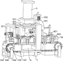
Fig. 1 is a schematic view of the overall structure of the present invention.
FIG. 2 is a schematic view of the chain connection of the present invention.
Figure 3 is a schematic view of the location of the tooth forming mechanism of the present invention.
Fig. 4 is a schematic structural diagram of the feeding mechanism of the present invention.
Fig. 5 is a schematic diagram of the second push rod position according to the present invention.
FIG. 6 is a schematic view of the connection between the pressing table and the waste bin of the present invention.
Fig. 7 is a schematic view of the position of the grinding mechanism of the present invention.
Figure 8 is a schematic view of the connector tile connection of the present invention.
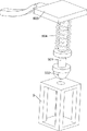
FIG. 9 is a exploded view of the stop guide linkage of the present invention.
Fig. 10 is a schematic view of the gathering rod of the present invention.
In the reference symbols: 1. Base, 101, support frame, 102, motor base, 103, first motor, 104, power base, 105, rotating shaft, 106, sprocket, 107, chain, 108, bearing frame, 109, permanent magnet, 2, feeding table, 201, support table, 202, first support, 203, first push rod, 204, first tension spring, 205, second support, 206, second push rod, 207, second tension spring, 208, material pushing plate, 209, feeding contact block, 210, material discharging frame, 211, fixing rod, 212, resetting rod, 213, resetting spring, 3, first cylinder, 301, material pressing plate, 302, power block, 303, first pressing plate, 304, second pressing plate, 305, material pressing table, 306, waste bin, 4, first fixing plate, 401, second fixing plate, 403, third tension spring, material discharging frame, 211, auxiliary plate, 405, guide rod, 406, pressing plate, 407, first spring, 408, pressing plate, 5, feeding table, 201, resetting rod, resetting spring, 213, resetting spring, pressing plate, clamping plate, the device comprises a limiting frame 501, a limiting guide rod 502, a triggering block 503, a limiting plate 504, a second spring 505, a triggering rod 6, a polishing frame 601, a second cylinder 602, a sliding plate 603, a polishing motor 604, a first grooved wheel 605, a second grooved wheel 606, a first belt 607, a polishing wheel 7, a guide frame 701, an upper protective shell 702, a fourth tension spring 703, a lower protective shell 704, a fifth tension spring 705, a furling rod 706, a protective shell contact rod 8, a blanking rod 801, a blanking claw 802 and a material collecting box.
Detailed Description
Embodiments of the present invention will be described in detail below with reference to the accompanying drawings.
Example 1
A metal fork stamping device is shown in figures 1-10 and comprises a base 1, a support frame 101, a motor base 102, a first motor 103, a power base 104, rotating shafts 105, chain wheels 106, chains 107, a bearing frame 108, permanent magnets 109, a feeding mechanism, a tooth punching mechanism and a pressing mechanism, wherein the support frame 101 is fixedly connected to the base 1, the support frame 101 is in an inverted L shape, the motor base 102 is arranged on the left side of the base 1, the first motor 103 is arranged on the motor base 102, the two power bases 104 are arranged on the front side of the base 1, the two rotating shafts 105 are rotatably connected to the two power bases 104, the two chain wheels 106 are fixedly connected to the two rotating shafts 105, the chains 107 are wound on the two chain wheels 106 together, the bearing frame 108 is arranged on the chain 107 in an annular array, the permanent magnets 109 are arranged on the bearing frame 108, the permanent magnets 109 are in a horizontal L shape, and the protrusions are positioned on the right sides of the tops of the permanent magnets 109, the base 1 is connected with a feeding mechanism, the feeding mechanism carries out intermittent feeding on a metal fork blank needing tooth punching, the base 1 is connected with a tooth punching mechanism, the tooth punching mechanism carries out tooth punching processing on the metal fork blank, the base 1 is connected with a pressing mechanism, and the pressing mechanism carries out pressing processing on the metal fork blank needing tooth punching.
Before working, a plurality of metal fork blanks needing to be subjected to tooth punching are manually placed on a feeding mechanism, the metal fork blanks can be placed at one time, then the tooth punching mechanism is controlled to be started, the feeding mechanism is driven to feed when the tooth punching mechanism is started, the feeding mechanism can push the metal fork blanks needing to be subjected to tooth punching to a permanent magnet on the right side, meanwhile, the tooth punching mechanism can drive a pressing mechanism to press the metal fork blanks below, after the tooth punching mechanism is reset, a first motor 103 is started to drive a rotating shaft 105 on the left side to rotate, so that a chain wheel 106 on the left side is driven to rotate, a chain 107 is driven to transmit rightwards, a bearing frame 108 is driven to transmit rightwards, the permanent magnet 109 with the metal fork blanks is transmitted rightwards, when the metal fork blanks are positioned on the lower side of the pressing mechanism, the first motor 103 is controlled to stop at the moment, and then the tooth punching mechanism is started again, at the moment, the tooth punching mechanism carries out primary tooth punching treatment on the metal fork blank on the lower side, the head of the metal fork blank is divided into two parts from the middle by the primary tooth punching treatment, after the tooth punching mechanism is reset, the first motor 103 is started again, so that the metal fork blank which is subjected to the primary tooth punching treatment is conveyed rightwards, another metal fork blank which is not subjected to the tooth punching treatment is conveyed rightwards, when the metal fork blank which is not subjected to the tooth punching treatment moves to the lower side of the tooth punching mechanism, the first motor 103 is stopped again at the moment, then the tooth punching mechanism is started, the tooth punching mechanism carries out primary tooth punching treatment on the metal fork blank which is not subjected to the tooth punching treatment, meanwhile, the tooth punching mechanism carries out secondary tooth punching treatment on the metal fork blank which is subjected to the primary tooth punching treatment, and the head of the metal fork is divided into four parts by the secondary tooth punching treatment, when the tooth punching mechanism is reset again, the first motor 103 is started again, so that the metal fork blank which is not subjected to tooth punching treatment is conveyed to the lower side of the tooth punching mechanism again, the metal fork blank subjected to tooth punching treatment for the first time is conveyed rightwards, the metal fork blank subjected to tooth punching treatment for the second time is conveyed rightwards and discharged, and therefore a complete working cycle is formed; this device can be automatic to the automatic intermittent type material loading of metal fork idiosome, then carry out twice processing of gulleting to metal fork idiosome, can compress tightly metal fork idiosome automatically before carrying out the processing of gulleting to metal fork to material loading, the processing of gulleting for the first time, the processing of gulleting for the second time and compress tightly for synchronous operation, thereby make the production efficiency of device higher.
Example 2
On the basis of embodiment 1, as shown in fig. 3, 4 and 5, the feeding mechanism includes a feeding table 2, a supporting table 201, a first support 202, a first push rod 203, a first tension spring 204, a second support 205, a second push rod 206, a second tension spring 207, a material pushing plate 208, a feeding contact block 209, a material placing frame 210, a fixing rod 211, a restoring rod 212 and a restoring spring 213, the feeding table 2 is fixedly connected to the left side of the base 1, the top of the feeding table 2 is formed by a plane and a curved surface, a surface formed by the combination of the plane and the curved surface is matched with the shape of the metal fork blank, the supporting table 201 is fixedly connected to the feeding table 2, the supporting table 201 plays a supporting role, the first support 202 is fixedly connected to the right side of the feeding table 2, the first push rod 203 is slidably connected to the first support 202, a semicircular convex block is arranged at the right end of the first push rod 203, the first push rod 203 and the first support 202 are jointly connected to the first tension spring 204, the left side of the feeding table 2 is fixedly connected to the second support 205, a second push rod 206 is connected on the second bracket 205 in a sliding manner, a semicircular bump is arranged at the rear end of the second push rod 206, the second push rod 206 is matched with the first push rod 203, the second push rod 206 and the second bracket 205 are connected with a second tension spring 207 together, a push plate 208 is connected on the feeding table 2 in a sliding manner, the push plate 208 is composed of a bent panel, an L-shaped plate and a cuboid plate, the bending degree of the bent panel is matched with the steel fork blank, the shape of the right end of the combined bent panel and the L-shaped plate is matched with the shape of the left end of the metal fork, the height of the cuboid is lower than that of the L-shaped plate, the difference height is equal to the thickness of the metal fork blank, a feeding contact block 209 is fixedly connected on the push plate 208, the feeding contact block 209 is a semicircular cylinder, the feeding contact block 209 is matched with the second push rod 206, a discharging frame 210 is arranged on the supporting table 201, and the distance between the discharging frame 210 and the feeding table 2 can be just equal to the metal fork blank, the fixing rod 211 is fixedly connected to the lower side of the material pushing plate 208, the resetting rod 212 is connected to the fixing rod 211 in a sliding mode, the right end of the resetting rod 212 is fixedly connected to the feeding table 2, the resetting rod 212 is sleeved with a resetting spring 213, and the resetting spring 213 is used for providing resetting force for the fixing rod 211.
Before working, the metal fork blank needing tooth punching is manually placed on the feeding table 2, the handle of the metal fork blank is positioned in the material placing frame 210, and the cuboid plate on the front side of the material pushing plate 208 can support the front end of the handle of the metal fork blank and can be placed in a plurality of positions at one time; when the tooth punching mechanism is started, at the moment, one of the permanent magnets 109 is located at a position which is slightly right in front of the feeding table 2, the tooth punching mechanism pushes the first push rod 203 leftward and stretches the first tension spring 204, so that the first push rod 203 pushes the second push rod 206 forward and stretches the second tension spring 207, the material pushing plate 208 moves rightward through the feeding contact block 209 and compresses the return spring 213, the material pushing plate 208 pushes the metal fork blank rightward onto the permanent magnet 109, the handle part of the metal fork is blocked by the stopper at the right side of the top of the permanent magnet 109, the handle part of the metal fork is clamped together with the material pushing plate 208, the position deviation of the metal fork can be prevented, the permanent magnet 109 can suck the metal fork tightly, feeding is completed, and at the moment, the tooth punching mechanism starts to reset upward; when the tooth punching mechanism is reset upwards, the first push rod 203 is not pushed leftwards any more, at the moment, the first tension spring 204 drives the first push rod 203 to slide rightwards for resetting, the second tension spring 207 drives the second push rod 206 to slide backwards for resetting, and the reset spring 213 drives the material pushing plate 208 to slide leftwards for resetting through the fixing rod 211; can carry out intermittent type material loading automatically through feed mechanism to do not need the manual work to place the metal fork embryo spare in the processing position one by one again, improved work efficiency and saved the manpower.
Example 3
On the basis of embodiment 2, as shown in fig. 3 and fig. 6, the tooth punching mechanism includes a first cylinder 3, a material pressing plate 301, a power block 302, a first pressing plate 303, a second pressing plate 304, a material pressing table 305 and a waste material box 306, the first cylinder 3 is installed on the support frame 101, the material pressing plate 301 is installed on the telescopic shaft of the first cylinder 3, the material pressing plate 301 is composed of a cylinder and a cube, the power block 302 is fixedly connected to the left side of the material pressing plate 301, the power block 302 can be matched with the first push rod 203, the first pressing plate 303 is installed on the lower side of the material pressing plate 301, the first pressing plate 303 is a pressing mold capable of performing primary tooth punching on a steel fork blank, the second pressing plate 304 is installed on the lower side of the material pressing plate 301, the second pressing mold capable of performing secondary tooth punching on the steel fork blank is installed on the base 1, the material pressing table 305 is installed on the base 1, the curved surface shape of the top of the material pressing table 305 is matched with the shape of the metal fork blank, set up three through-hole that is used for the waste material that drops on pressing material platform 305, a left through-hole corresponds first clamp plate 303, and two through-holes on right side correspond second clamp plate 304, press material platform 305 to be located and press clamp plate 301 below, press material platform 305 downside to place dump bin 306.
When the first motor 103 stops, the metal fork blank on the lower side of the first pressing plate 303 has not been subjected to the first tooth punching process, the metal fork blank on the lower side of the second pressing plate 304 has been subjected to the first tooth punching process, and the bottoms of the two metal fork blanks are in sliding contact with the material pressing table 305, then the first air cylinder 3 is controlled to extend downward, so as to drive the material pressing plate 301 to move downward, so as to drive the power block 302 to move downward, the power block 302 will press the first push rod 203 leftward when moving downward, so as to make the first push rod 203 slide rightward, the material pressing plate 301 will drive the pressing mechanism to press the metal fork blanks below the first pressing plate 303 and the second pressing plate 304 when moving downward, the material pressing plate 301 will drive the first pressing plate 303 and the second pressing plate 304 to move downward, so that the head of the metal fork blank which is not subjected to the tooth punching process will be divided into two parts by the first pressing plate 303, meanwhile, the second pressing plate 304 divides the head of the metal fork blank subjected to the primary tooth punching treatment into four parts, waste materials generated in the tooth punching treatment process fall into a waste material box 306 through a through hole in a pressing table 305, so that the tooth punching treatment of the metal fork blank is completed, and then the first air cylinder 3 is controlled to contract, so that the pressing plate 301 is driven to move upwards, the power block 302 does not extrude the first push rod 203 rightwards any more, and the pressing plate 301 moves upwards to drive the first pressing plate 303 and the second pressing plate 304 to move upwards, so that the resetting is completed; can be automatic through tooth punching mechanism open the tooth to the metal fork and handle to can open the tooth and handle for the second time to the metal fork in step, thereby make the efficiency of opening the tooth higher, and can get up the garbage collection that tooth punching produced, thereby make things convenient for the recycle to the resource, and be favorable to keeping production environment clean and tidy.
As shown in fig. 7 and 8, the pressing mechanism includes a first fixing plate 4, a second fixing plate 401, a third tension spring 402, a connecting plate 403, an auxiliary plate 404, a guide rod 405, a pressing plate 406, a first spring 407 and a lower pressing plate 408, the first fixing plate 4 is fixedly connected to the front side of the base 1, the second fixing plate 4 is fixedly connected to the second fixing plate 401, the third tension spring 402 is connected to the second fixing plate 401, the connecting plate 403 is slidably connected to the second fixing plate 401, the end of the third tension spring 402 away from the second fixing plate 401 is connected to the connecting plate 403, the third tension spring 402 can provide an upward returning force to the connecting plate 403, two auxiliary plates 404 are fixedly connected to the connecting plate 403 symmetrically on both sides, two guide rods 405 are slidably connected to the two auxiliary plates 404 symmetrically, the pressing plate 406 is fixedly connected to the lower ends of the two guide rods 405, the pressing plate 406 is provided with three bumps on the lower side, the bumps are L-shaped, the bumps can be matched with the permanent magnet 109 to clamp a handle of a metal fork blank, the two bumps on the left side correspond to the metal fork blank on the lower sides of the first pressing plate 303 and the second pressing plate 304, the two guide rods 405 are sleeved with first springs 407, the first springs 407 can provide downward moving force for the pressing plate 406, the pressing plate 301 is fixedly connected with a lower pressing plate 408, and the lower pressing plate 408 is matched with the connecting plate 403.
When the first motor 103 stops, the metal fork blank which is not subjected to the tooth punching processing and completes the first tooth punching processing is positioned on the pressing plate 406 and below the two left lugs; when the pressing plate 301 moves downwards, the pressing plate 408 is driven to move downwards, the pressing plate 408 moves downwards to contact with the connecting plate 403 and drive the connecting plate 403 to slide downwards on the second fixing plate 401, the connecting plate 403 stretches the third tension spring 402 when moving downwards, the connecting plate 403 drives the auxiliary plates 404 on two sides to move downwards when moving downwards, so that the pressing plate 406 moves downwards, the pressing plate 406 contacts with the permanent magnet 109 and then starts to compress the first spring 407, so that the metal fork blank which is not subjected to the tooth punching treatment and completes the first tooth punching treatment is pressed by the pressing plate 406, the tooth punching treatment of the metal fork blank is facilitated, and the first spring 407 can play a role in buffering protection, so that the metal fork blank and the permanent magnet 109 are prevented from being damaged by the pressing plate 406; when the pressing plate 301 moves upward, the lower pressing plate 408 is driven to move upward, so that the lower pressing plate 408 no longer presses the engaging plate 403 downward, and thus the third tension spring 402 drives the engaging plate 403 to slide upward on the second fixing plate 401, thereby driving the two auxiliary plates 404 to move upward, and thus driving the lower pressing plate 408 to move upward through the two guide rods 405, thereby completing the reposition; the metal fork blank can be compressed through the compressing mechanism, so that the metal fork blank can be conveniently subjected to tooth punching, the metal fork handle does not need to be manually held to perform tooth punching, and the safety of workers is guaranteed.
As shown in fig. 4 and 6, the metal fork blank loading device further comprises a limiting mechanism, the limiting mechanism comprises a limiting frame 5, a limiting guide rod 501, a trigger block 502, a limiting plate 503, a second spring 504 and a trigger rod 505, the limiting frame 5 is fixedly connected to the right side of the loading platform 2, the limiting guide rod 501 is slidably connected to the limiting frame 5, the trigger block 502 is fixedly connected to the bottom end of the limiting guide rod 501, the lower end of the trigger block 502 is a curved surface, the limiting plate 503 is fixedly connected to the top of the limiting guide rod 501, the curved surface at the left end of the limiting plate 503 is matched with the curved surface at the right end of the head of the metal fork blank, the second spring 504 is sleeved on the limiting guide rod 501, the second spring 504 can provide downward resetting force for the limiting plate 503, the trigger rod 505 is fixedly connected to the fixed rod 211, the right end of the trigger rod 505 is an inclined plane, and the trigger rod 505 is matched with the trigger block 502.
When the fixing rod 211 moves rightwards, the triggering rod 505 is driven to slide rightwards, when the triggering rod 505 slides rightwards, the triggering rod is in contact with the bottom of the triggering block 502 and presses the triggering block 502 upwards, so that the triggering block 502 moves upwards, the limiting guide rod 501 slides upwards and compresses the second spring 504, the limiting plate 503 is driven to move upwards, at the moment, the pushing plate 208 pushes the metal fork blank rightwards onto the permanent magnet 109, the limiting plate 503 can prevent the head of the metal fork blank from moving rightwards continuously, and the metal fork blank is clamped by the pushing plate 208 and the limiting plate 503, so that the position of the metal fork blank is prevented from being deviated; when the fixing rod 211 is reset leftwards, the trigger block 502 is no longer pressed upwards by the fixing rod 211, and the second spring 504 pushes the limiting guide rod 501 to move downwards, so that the limiting plate 503 is driven to move downwards for resetting; can carry out spacingly to the metal fork embryo spare that carries out the material loading through stop gear to prevent to carry out the in-process position of material loading at the metal fork embryo spare and can take place the skew, thereby be favorable to guaranteeing the accuracy of gulleting position.
As shown in fig. 7 and fig. 10, the polishing machine further comprises a polishing mechanism, the polishing mechanism comprises a polishing frame 6, a second cylinder 601, a sliding plate 602, a polishing motor 603, a first sheave 604, a second sheave 605, a first belt 606 and a polishing wheel 607, the polishing frame 6 is arranged on the right side of the base 1, the second cylinder 601 is installed on the polishing frame 6, a sliding plate 602 is connected to a telescopic shaft of the second cylinder 601, the sliding plate 602 is slidably connected to the polishing frame 6, the sliding plate 602 can horizontally slide back and forth on the polishing frame 6, the polishing frame 6 is provided with the polishing motor 603, a rotating shaft of the polishing motor 603 is provided with the first sheave 604, the polishing motor 603 can drive the first sheave 604 to rotate, one side of the sliding plate 602 away from the polishing motor 603 is rotatably connected with the second sheave 605, the first sheave 604 and the second sheave 605 are together wound with the first belt 606, the first sheave 604 drives the second sheave 605 to rotate through the first belt 606, a grinding wheel 607 is rotatably connected to the sliding plate 602, and two annular grooves are formed on the grinding wheel 607, the grinding wheel 607 is divided into three parts by the notches, and the three parts can be inserted into three gaps between the teeth of the metal fork blank, and the grinding wheel 607 is coaxial with the second grooved pulley 605.
When the first motor 103 stops, the metal fork blank having completed the second tooth punching process is located right in front of the grinding wheel 607, and the protrusion on the right side of the lower portion of the pressing plate 406 in the pressing mechanism presses the metal fork blank right in front of the grinding wheel 607, then the grinding motor 603 is started to drive the first sheave 604 to rotate, so as to drive the second sheave 605 to rotate through the first belt 606, so as to drive the grinding wheel 607 to rotate, and then the second cylinder 601 is controlled to extend, so as to drive the sliding plate 602 to slide forward, so as to drive the grinding motor 603, the first sheave 604, the second sheave 605, the first belt 606, and the grinding wheel 607 to synchronously move forward, when the grinding wheel 607 contacts with the metal fork blank, the metal fork blank is ground, and the fork tooth portions of the metal fork blank enter the grooves on the grinding wheel 607, so as to grind the tooth portions of the metal fork blank, then the second cylinder 601 is controlled to contract, so as to drive the sliding plate 602 to slide backwards, so as to drive the grinding motor 603, the first grooved pulley 604, the second grooved pulley 605, the first belt 606 and the grinding wheel 607 to synchronously move backwards, so as to complete resetting, and the grinding motor 603 is stopped when the grinding wheel 607 is separated from the metal fork blank; the gear rod of the metal fork blank can be automatically polished through the polishing mechanism, so that the gear rod part of the metal fork blank is smoother, and the process of manually polishing the gear rod is omitted.
As shown in fig. 3, fig. 7 and fig. 10, the protection mechanism further comprises a guide frame 7, an upper protective shell 701, a fourth tension spring 702, a lower protective shell 703, a fifth tension spring 704, a furling rod 705 and a protective shell touch rod 706, the guide frame 7 is fixedly connected to the right side of the base 1, the upper protective shell 701 is slidably connected to the guide frame 7, the upper protective shell 701 can slide on the guide frame 7 in the vertical direction, the upper protective shell 701 and the guide frame 7 are commonly connected with the fourth tension spring 702, the fourth tension spring 702 can provide upward return force for the upper protective shell 701, the lower protective shell 703 is slidably connected to the guide frame 7, the lower protective shell 703 can slide on the guide frame 7 in the vertical direction, the fifth tension spring 704 is commonly connected to the lower protective shell 703 and the guide frame 7, the fifth tension spring 704 is used for pulling the lower protective shell 703 to return downward, the furling rod 705 is installed on the front side of the sliding plate 602, the furling rod 705 is Y-shaped, the upper shell 701 and the lower shell 703 are symmetrically and fixedly connected with two protective shell touch rods 706, both sheath contact rods 706 cooperate with the gathering rod 705.
When the sliding plate 602 moves forward, the furling rod 705 is driven to move forward, when the furling rod 705 is in contact with the two casing contact rods 706 and continues to move forward, the two casing contact rods 706 drive the upper casing 701 to slide downward and stretch the fourth tension spring 702, and simultaneously the lower casing 703 slides upward and stretches the fifth tension spring 704, so that the upper casing 701 and the lower casing 703 are driven to approach each other, the upper casing 701 and the lower casing 703 cannot be closed, the normal operation of the grinding mechanism cannot be influenced, and iron filings can be prevented from splashing in the process of grinding the metal fork blank, so that the safety of workers is protected; when the sliding plate 602 slides backwards, the furling rod 705 is driven to move backwards, at this time, the fourth tension spring 702 drives the upper protective shell 701 to slide upwards for resetting, and the fifth tension spring 704 drives the lower protective shell 703 to slide downwards for resetting, so that resetting is completed; can prevent through protection machanism that iron fillings from splashing out when polishing metal fork embryo spare to the potential safety hazard in the course of working has been reduced.
As shown in fig. 7 and 10, the blanking device further comprises a blanking mechanism, the blanking mechanism comprises a blanking rod 8, a blanking claw 801 and a receiving box 802, the blanking rod 8 is fixedly connected to the right side of the upper protective shell 701, the blanking claw 801 is fixedly connected to the blanking rod 8, two grabbing rods are arranged on the blanking claw 801, the distance between the two grabbing rods on the blanking claw 801 is larger than the handle width of the metal fork blank but smaller than the head width of the metal fork blank, the receiving box 802 is arranged on the right side of the base 1, and the receiving box 802 is located below the blanking claw 801.
When the first motor 103 stops, the connecting part of the handle and the head of the metal fork blank which is subjected to the grinding treatment is positioned at the lower side of the blanking claw 801; when the upper protective shell 701 moves downwards, the blanking rod 8 is driven to move downwards, the blanking claw 801 is driven to move downwards, the connection part of the handle and the head of the metal fork blank is pressed downwards by the blanking claw 801, the metal fork blank is separated from the permanent magnet 109, and the metal fork blank falls into the material receiving box 802, so that automatic blanking is completed; when the upper protective shell 701 moves upwards, the blanking rod 8 is driven to move upwards to reset, the blanking claw 801 is driven to move upwards to reset, blanking processing can be automatically carried out through the blanking mechanism, and the step of manual blanking is omitted.
The above description is only an embodiment of the present invention, and not intended to limit the scope of the present invention, and all modifications of equivalent structures and equivalent processes, which are made by the present specification, or directly or indirectly applied to other related technical fields, are included in the scope of the present invention.
Claims (7)
1. A metal fork stamping device comprises a base (1), a support frame (101) and a motor base (102), wherein the support frame (101) is fixedly connected to the base (1), the motor base (102) is arranged on the left side of the base (1), and the metal fork stamping device is characterized by further comprising a first motor (103), a power base (104), rotating shafts (105), chain wheels (106), chains (107), a bearing frame (108), permanent magnets (109), a tooth punching mechanism and a pressing mechanism, the first motor (103) is installed on the motor base (102), the front side of the base (1) is rotatably connected with the two rotating shafts (105) through the two power bases (104), the two rotating shafts (105) are wound with the chains (107) through the two chain wheels (106), the chains (107) are provided with a plurality of bearing frames (108) for conveying fork blanks, the permanent magnets (109) are installed on the bearing frames (108), the base (1) is connected with the tooth punching mechanism for tooth punching treatment of the fork blanks, the base (1) is connected with a pressing mechanism for pressing a fork blank needing to be toothed; the tooth punching mechanism comprises a first cylinder (3), a material pressing plate (301), a power block (302), a first pressing plate (303), a second pressing plate (304), a material pressing table (305) and a waste box (306), wherein the first cylinder (3) is installed on a support frame (101), the material pressing plate (301) is installed on a telescopic shaft of the first cylinder (3), the power block (302) is fixedly connected to the left side of the material pressing plate (301), the first pressing plate (303) and the second pressing plate (304) are installed on the lower side of the material pressing plate (301), the material pressing table (305) is installed on a base (1), and the waste box (306) is placed on the lower side of the material pressing table (305).
2. A metal fork punching device according to claim 1, wherein the pressing mechanism comprises a first fixing plate (4), a second fixing plate (401), a third tension spring (402) and an engaging plate (403), auxiliary plate (404), guide bar (405), pressure strip (406), first spring (407) and holding down plate (408), base (1) front side has second fixed plate (401) through first fixed plate (4) rigid coupling, sliding connection has linkage plate (403) and be connected with third extension spring (402) between second fixed plate (401), there are two guide bar (405) through two auxiliary plate (404) sliding connection on linkage plate (403), the common rigid coupling of two guide bar (405) lower extreme has pressure strip (406), all overlap on two guide bar (405) and have first spring (407), the rigid coupling has holding down plate (408) that are used for driving linkage plate (403) downstream on pressure plate (301).
3. The metal fork stamping device according to claim 1, characterized by further comprising a feeding mechanism for automatically feeding the fork blank, wherein the feeding mechanism is mounted on the base (1), the feeding mechanism comprises a feeding table (2), a supporting table (201), a first support (202), a first push rod (203), a first tension spring (204), a second support (205), a second push rod (206), a second tension spring (207), a material pushing plate (208), a feeding contact block (209), a material discharging frame (210), a fixing rod (211), a reset rod (212) and a reset spring (213), the feeding table (2) is fixedly connected to the left side of the base (1), the supporting table (201) is fixedly connected to the feeding table (2), the feeding table (2) is slidably connected with the first push rod (203) matched with the power block (302) through the first support (202), and the first tension spring (204) is commonly connected to the first push rod (203) and the first support (202), feeding table (2) is connected with second push rod (206) with first push rod (203) complex through second support (205) sliding connection, second push rod (206) and second support (205) are connected with second extension spring (207) jointly, sliding connection has scraping wings (208) on feeding table (2), the rigid coupling has material loading touch multitouch (209) with second push rod (206) complex on scraping wings (208), install blowing frame (210) on brace table (201), scraping wings (208) have release link (212) with feeding table (2) rigid coupling through dead lever (211) sliding connection, the cover has reset spring (213) on release link (212).
4. The metal fork stamping device according to claim 3, characterized by further comprising a limiting mechanism for limiting the fork blank during feeding, wherein the limiting mechanism is mounted on the feeding table (2) and comprises a limiting frame (5), a limiting guide rod (501), a trigger block (502), a limiting plate (503), a second spring (504) and a trigger rod (505), the limiting frame (5) is fixedly connected to the right side of the feeding table (2), the limiting guide rod (501) is slidably connected to the limiting frame (5), the trigger block (502) and the limiting plate (503) are respectively fixedly connected to the limiting guide rod (501), the second spring (504) is sleeved on the limiting guide rod (501), and the trigger rod (505) matched with the trigger block (502) is fixedly connected to the fixing rod (211).
5. The metal fork stamping device according to claim 2, further comprising a polishing mechanism for polishing the rack bar of the fork blank, wherein the polishing mechanism comprises a polishing frame (6), a second cylinder (601), a sliding plate (602), a polishing motor (603), a first sheave (604), a second sheave (605), a first belt (606) and a polishing wheel (607), the polishing frame (6) is arranged on the right side of the base (1), the second cylinder (601) is arranged on the polishing frame (6), the sliding plate (602) which is connected with the polishing frame (6) in a sliding manner is connected on a telescopic shaft of the second cylinder (601), the polishing motor (603) is arranged on the polishing frame (6), the first sheave (604) is arranged on a rotating shaft of the polishing motor (603), the second sheave (605) is rotatably connected on the sliding plate (602), and a first belt (606) is wound on the first sheave (604) and the second sheave (605) together, the sliding plate (602) is rotatably connected with a grinding wheel (607) which is coaxial with the second grooved wheel (605).
6. The metal fork stamping device according to claim 5, further comprising a protection mechanism for preventing iron filings from splashing, wherein the protection mechanism is located on the right side of the base (1), the protection mechanism comprises a guide frame (7), an upper protection shell (701) and a fourth tension spring (702), the novel folding device comprises a lower protective shell (703), a fifth tension spring (704), a folding rod (705) and a protective shell touch rod (706), wherein a guide frame (7) is fixedly connected to the right side of a base (1), an upper protective shell (701) and a lower protective shell (703) are respectively connected to the guide frame (7) in a sliding mode, the upper protective shell (701) and the guide frame (7) are jointly connected with a fourth tension spring (702), the lower protective shell (703) and the guide frame (7) are jointly connected with the fifth tension spring (704), the folding rod (705) is installed on the front side of a sliding plate (602), and two protective shell touch rods (706) matched with the folding rod (705) are symmetrically and fixedly connected to the upper protective shell (701) and the lower protective shell (703).
7. A metal fork stamping device according to claim 6, characterized by further comprising a blanking mechanism for automatically blanking the fork blank, wherein the blanking mechanism is located on the right side of the base (1), the blanking mechanism comprises a blanking rod (8), a blanking claw (801) and a material receiving box (802), the blanking rod (8) is fixedly connected to the right side of the upper protective shell (701), the blanking claw (801) is fixedly connected to the blanking rod (8), the material receiving box (802) is arranged on the right side of the base (1), and the material receiving box (802) is located below the blanking claw (801).
Priority Applications (1)
| Application Number | Priority Date | Filing Date | Title |
|---|---|---|---|
| CN202210872795.XA CN115069873B (en) | 2022-07-24 | 2022-07-24 | Metal fork stamping device |
Applications Claiming Priority (1)
| Application Number | Priority Date | Filing Date | Title |
|---|---|---|---|
| CN202210872795.XA CN115069873B (en) | 2022-07-24 | 2022-07-24 | Metal fork stamping device |
Publications (2)
| Publication Number | Publication Date |
|---|---|
| CN115069873A true CN115069873A (en) | 2022-09-20 |
| CN115069873B CN115069873B (en) | 2023-03-10 |
Family
ID=83242662
Family Applications (1)
| Application Number | Title | Priority Date | Filing Date |
|---|---|---|---|
| CN202210872795.XA Active CN115069873B (en) | 2022-07-24 | 2022-07-24 | Metal fork stamping device |
Country Status (1)
| Country | Link |
|---|---|
| CN (1) | CN115069873B (en) |
Cited By (1)
| Publication number | Priority date | Publication date | Assignee | Title |
|---|---|---|---|---|
| CN115351167A (en) * | 2022-10-19 | 2022-11-18 | 徐州坤达门窗有限公司 | Door and window pulley bracket stamping device |
Citations (8)
| Publication number | Priority date | Publication date | Assignee | Title |
|---|---|---|---|---|
| KR20140055385A (en) * | 2012-10-31 | 2014-05-09 | 허남훈 | Device for spoon or fork |
| CN107041668A (en) * | 2016-02-05 | 2017-08-15 | 有进可莱贝思株式会社 | Tableware manufacture method |
| CN109290896A (en) * | 2018-09-01 | 2019-02-01 | 浙江众亿智能科技有限公司 | A kind of fork handle surface batch grinding device of fork |
| CN111375674A (en) * | 2020-03-21 | 2020-07-07 | 冯程阳 | Stainless steel tableware forming and processing technology |
| CN111702098A (en) * | 2020-06-22 | 2020-09-25 | 刘建 | Stainless steel soup ladle punching machine |
| CN111922234A (en) * | 2020-09-23 | 2020-11-13 | 刘扬 | Improved continuous reciprocating type mechanical stamping equipment |
| CN212264257U (en) * | 2020-05-08 | 2021-01-01 | 滨州阳信华美不锈钢制品股份有限公司 | A full-automatic oil press for preparing high performance stainless steel knife, fork and spoon |
| CN114749546A (en) * | 2022-04-21 | 2022-07-15 | 丁燕瑞 | Fork processing equipment |
-
2022
- 2022-07-24 CN CN202210872795.XA patent/CN115069873B/en active Active
Patent Citations (8)
| Publication number | Priority date | Publication date | Assignee | Title |
|---|---|---|---|---|
| KR20140055385A (en) * | 2012-10-31 | 2014-05-09 | 허남훈 | Device for spoon or fork |
| CN107041668A (en) * | 2016-02-05 | 2017-08-15 | 有进可莱贝思株式会社 | Tableware manufacture method |
| CN109290896A (en) * | 2018-09-01 | 2019-02-01 | 浙江众亿智能科技有限公司 | A kind of fork handle surface batch grinding device of fork |
| CN111375674A (en) * | 2020-03-21 | 2020-07-07 | 冯程阳 | Stainless steel tableware forming and processing technology |
| CN212264257U (en) * | 2020-05-08 | 2021-01-01 | 滨州阳信华美不锈钢制品股份有限公司 | A full-automatic oil press for preparing high performance stainless steel knife, fork and spoon |
| CN111702098A (en) * | 2020-06-22 | 2020-09-25 | 刘建 | Stainless steel soup ladle punching machine |
| CN111922234A (en) * | 2020-09-23 | 2020-11-13 | 刘扬 | Improved continuous reciprocating type mechanical stamping equipment |
| CN114749546A (en) * | 2022-04-21 | 2022-07-15 | 丁燕瑞 | Fork processing equipment |
Cited By (2)
| Publication number | Priority date | Publication date | Assignee | Title |
|---|---|---|---|---|
| CN115351167A (en) * | 2022-10-19 | 2022-11-18 | 徐州坤达门窗有限公司 | Door and window pulley bracket stamping device |
| CN115351167B (en) * | 2022-10-19 | 2023-09-01 | 徐州坤达门窗有限公司 | Door and window pulley support stamping device |
Also Published As
| Publication number | Publication date |
|---|---|
| CN115069873B (en) | 2023-03-10 |
Similar Documents
| Publication | Publication Date | Title |
|---|---|---|
| CN115069873B (en) | Metal fork stamping device | |
| CN111702091A (en) | Automatic feeding and discharging device of stamping machine tool | |
| CN113084070A (en) | Automatic hammer forging machine of upset forging clearance workstation waste residue | |
| CN113732290A (en) | New energy automobile gearbox gear machine-shaping equipment | |
| CN116900159A (en) | Hardware mold with automatic feeding function | |
| CN116460200B (en) | Forming device of ring flange | |
| CN113070765A (en) | Metal strainer grinding device for manufacturing and processing | |
| CN112873303A (en) | Polyurethane material design cutting device for new energy automobile | |
| CN108817146B (en) | A kind of L shape workpiece automatic bending machine | |
| CN116460202A (en) | Hardware gasket stamping system | |
| CN113786897B (en) | Temporary garbage treatment device for construction site | |
| CN112659254B (en) | Rubber pad part punching machine | |
| CN109175136A (en) | A kind of mould punching automatic discharge apparatus | |
| CN211990614U (en) | Stamping workpiece discharge apparatus for punching machine | |
| CN112474937A (en) | 303 stainless steel round bar equipment of bending | |
| CN112264859A (en) | Clothing button edge punching press unhairing limit equipment | |
| CN112497035A (en) | Promotion formula steel ball burnishing device | |
| CN218656350U (en) | Can collect stamping die of blanking clout | |
| CN201143545Y (en) | Waste material die cutting slide track | |
| CN218192222U (en) | Automatic unloader of single-stage flywheel inner core | |
| CN220739104U (en) | Multifunctional top bending machine for U-shaped steel | |
| CN213917269U (en) | Plate collecting mechanism of hydraulic plate shearing machine | |
| CN109093191A (en) | A kind of cutting equipment of box frame riveting die | |
| CN215941320U (en) | Punch blanking sorting device for producing motorcycle accessories | |
| CN220719596U (en) | Quick punching equipment |
Legal Events
| Date | Code | Title | Description |
|---|---|---|---|
| PB01 | Publication | ||
| PB01 | Publication | ||
| SE01 | Entry into force of request for substantive examination | ||
| SE01 | Entry into force of request for substantive examination | ||
| GR01 | Patent grant | ||
| GR01 | Patent grant |