CN115025507A - Ball type concentrator - Google Patents
Ball type concentrator Download PDFInfo
- Publication number
- CN115025507A CN115025507A CN202210668809.6A CN202210668809A CN115025507A CN 115025507 A CN115025507 A CN 115025507A CN 202210668809 A CN202210668809 A CN 202210668809A CN 115025507 A CN115025507 A CN 115025507A
- Authority
- CN
- China
- Prior art keywords
- jacket
- driving
- plate
- steam
- inner container
- Prior art date
- Legal status (The legal status is an assumption and is not a legal conclusion. Google has not performed a legal analysis and makes no representation as to the accuracy of the status listed.)
- Pending
Links
- 239000011229 interlayer Substances 0.000 claims abstract description 31
- 230000005540 biological transmission Effects 0.000 claims abstract description 25
- 238000010438 heat treatment Methods 0.000 claims abstract description 18
- 238000003756 stirring Methods 0.000 claims abstract description 10
- 239000007788 liquid Substances 0.000 claims description 48
- 239000000498 cooling water Substances 0.000 claims description 13
- 238000007599 discharging Methods 0.000 claims description 10
- 230000000149 penetrating effect Effects 0.000 claims description 3
- 238000009423 ventilation Methods 0.000 claims 1
- 239000010410 layer Substances 0.000 abstract description 12
- 230000000694 effects Effects 0.000 abstract description 7
- 239000003814 drug Substances 0.000 description 5
- 238000000034 method Methods 0.000 description 3
- 230000008569 process Effects 0.000 description 3
- 230000001133 acceleration Effects 0.000 description 2
- 238000003889 chemical engineering Methods 0.000 description 2
- 235000013305 food Nutrition 0.000 description 2
- 230000006872 improvement Effects 0.000 description 2
- 238000004519 manufacturing process Methods 0.000 description 2
- 238000007789 sealing Methods 0.000 description 2
- XLYOFNOQVPJJNP-UHFFFAOYSA-N water Substances O XLYOFNOQVPJJNP-UHFFFAOYSA-N 0.000 description 2
- 239000004278 EU approved seasoning Substances 0.000 description 1
- 240000007643 Phytolacca americana Species 0.000 description 1
- 238000010795 Steam Flooding Methods 0.000 description 1
- 230000001174 ascending effect Effects 0.000 description 1
- 230000009286 beneficial effect Effects 0.000 description 1
- 238000005842 biochemical reaction Methods 0.000 description 1
- 230000008859 change Effects 0.000 description 1
- 238000001816 cooling Methods 0.000 description 1
- 230000007547 defect Effects 0.000 description 1
- 238000010586 diagram Methods 0.000 description 1
- 238000000605 extraction Methods 0.000 description 1
- 230000002349 favourable effect Effects 0.000 description 1
- 239000002778 food additive Substances 0.000 description 1
- 235000013373 food additive Nutrition 0.000 description 1
- 235000011194 food seasoning agent Nutrition 0.000 description 1
- 230000036541 health Effects 0.000 description 1
- 239000000463 material Substances 0.000 description 1
- 238000012986 modification Methods 0.000 description 1
- 230000004048 modification Effects 0.000 description 1
- 239000003960 organic solvent Substances 0.000 description 1
- 238000005086 pumping Methods 0.000 description 1
- 230000009467 reduction Effects 0.000 description 1
- 239000010865 sewage Substances 0.000 description 1
- 239000000126 substance Substances 0.000 description 1
Images


Classifications
-
- B—PERFORMING OPERATIONS; TRANSPORTING
- B01—PHYSICAL OR CHEMICAL PROCESSES OR APPARATUS IN GENERAL
- B01D—SEPARATION
- B01D3/00—Distillation or related exchange processes in which liquids are contacted with gaseous media, e.g. stripping
- B01D3/02—Distillation or related exchange processes in which liquids are contacted with gaseous media, e.g. stripping in boilers or stills
-
- Y—GENERAL TAGGING OF NEW TECHNOLOGICAL DEVELOPMENTS; GENERAL TAGGING OF CROSS-SECTIONAL TECHNOLOGIES SPANNING OVER SEVERAL SECTIONS OF THE IPC; TECHNICAL SUBJECTS COVERED BY FORMER USPC CROSS-REFERENCE ART COLLECTIONS [XRACs] AND DIGESTS
- Y02—TECHNOLOGIES OR APPLICATIONS FOR MITIGATION OR ADAPTATION AGAINST CLIMATE CHANGE
- Y02E—REDUCTION OF GREENHOUSE GAS [GHG] EMISSIONS, RELATED TO ENERGY GENERATION, TRANSMISSION OR DISTRIBUTION
- Y02E10/00—Energy generation through renewable energy sources
- Y02E10/40—Solar thermal energy, e.g. solar towers
Abstract
The invention relates to a spherical concentrator, which is characterized in that a driving plate arranged in an interlayer is arranged on the basis of the interlayer and an inner container in the prior art, the driving plate is driven by a driving device to rotate in the circumferential direction to rotate the steam in the interlayer in the circumferential direction, the circumferential circulation of the steam is accelerated, meanwhile, a reciprocating plate is longitudinally and rotatably connected between the inner container and the driving plate, the reciprocating plate consists of two groups of hemispherical stirring plates which are vertically arranged, and a power transmission device is arranged between the rotating shaft and the reciprocating plate to drive the reciprocating plate to stir in a reciprocating manner in the up-and-down direction to drive the steam in the up-and-down direction to form multi-angle three-dimensional steam exchange by combining circumferential steam stirring, so that the inner container can be uniformly heated, the heat exchange of the upper layer and the lower layer in the interlayer is rapid, the heating effect is good, the practicality is strong, is fit for using widely.
Description
Technical Field
The invention belongs to the technical field of biochemical reaction instruments, and particularly relates to a spherical concentrator.
Background
The spherical concentrator mainly comprises four parts, namely a concentrator main body, a condenser, a gas-liquid separator and a liquid receiving barrel, and can be used for concentrating and distilling feed liquid and recovering organic solvents in the industries of pharmacy, food, chemical engineering and the like. The concentrator is a device of concentration production process in the industries of traditional Chinese medicine, health products, natural seasonings, food additives, food, chemical engineering and the like, and is widely applied to the fields of chemical industry, medicine production and processing industry, ore processing industry, sewage treatment and the like since the invention of the concentrator.
The concentrator main part bottom of current spherical concentrator is equipped with the clamp cover, be equipped with steam inlet on the clamp cover, the pipeline of steam inlet is connected with the steam channel of input steam through flange joint's mode, whole spherical concentrator is when carrying out the intensification operation mainly through steam inlet pouring steam into in the space between clamp cover and the inner bag, steam attaches to and carries out the temperature transfer on the inner bag outer wall and can realize carrying out the intensification operation to the inside liquid medicine of inner bag, and only local steam carries out the temperature transfer because attached to on the inner bag outer wall when this mode is carried out the intensification, the steam of other parts can influence the mutual transmission of temperature between the steam because not flow through, thereby can not be fast and as much as possible transmit steam temperature to the inner bag inside, thereby can make the intensification operation to the inner bag slower, to the problem, be CN201921388106.8 at patent application number, the patent application discloses a spherical concentrator for producing novel medicine patches, which comprises a condenser and a concentrator main body, wherein the condenser is vertically arranged on the parallel right side of the concentrator main body, the left side of the upper end of the condenser is provided with a gas-liquid separator, the condenser, the gas-liquid separator and the gas-liquid separator are fixedly connected with the concentrator main body through connecting pipelines, the concentrator main body is provided with a jacket and a liner, the jacket is sleeved outside the circumference of the lower half section of the liner, the outer wall of the left end of the uppermost side of the jacket is connected with a steam inlet, the center of the bottom of the jacket is connected with a temperature accelerating and increasing device, the bottoms of the jackets at the left side and the right side of the temperature accelerating and increasing device are respectively connected with a liquid discharge port B and a liquid discharge port A, the liquid discharge port B is positioned on the left side of the liquid discharge port A, the jacket is provided with a vertical pillar by the outer wall of the circumference, the inner container is provided with a feeding hole with an outward opening on the outer wall of the front end close to the upper side, the inner container is connected with a manhole on the outer wall of the left end close to the upper side, the inner container is provided with a vacuum meter interface and a thermometer interface on the outer wall of the right end close to the upper side, the vacuum meter interface is positioned on the left side of the thermometer interface, the upper end of the inner container is communicated and connected with a gas-liquid separator through a connecting pipeline, the temperature acceleration and reduction device is provided with a machine sleeve, the machine sleeve is connected on the outer wall of the bottom of a jacket through a nut, a sealing bearing is arranged inside the outer wall of the lowest end of the jacket, a small motor is arranged inside the circumference of the machine sleeve, the small motor and the machine sleeve are fixedly connected through a machine frame, the small motor is provided with an output shaft, the uppermost end of the output shaft penetrates through the sealing bearing and is arranged inside the jacket, a connecting sleeve is sleeved outside the circumference of the uppermost end of the output shaft, and the outer wall of the connecting sleeve is connected with an acceleration blade, the inside of accelerating blade is provided with the through-hole, little motor passes through external power source electric connection. The device can accelerate circulation after entering the gap space between the jacket and the inner container through the steam inlet, so that steam injected into the gap space between the jacket and the inner container can be quickly attached to the outer wall of the inner container, and the steam inside the jacket and the inner container can be always in a mutual exchange state through the stirring of the accelerating blades, so that the steam is more favorable for quickly transmitting heat to the inner container and transferring the heat to liquid medicine inside the inner container, however, the steam enters the interlayer above the jacket, so that the temperature of the steam above the interlayer is higher than that of the steam below the interlayer, and the rotating shaft of the accelerating blades is vertically arranged to rotate, so that the circumferential exchange of the steam is accelerated, the steam above the interlayer is still hotter than below the interlayer, so that the inner container is still in a state of being hot at the top and cold at the bottom, the inner container is unevenly heated, the heating effect is poor, and therefore, the improvement on the basis of the prior art is urgently needed, a ball type compressor is provided to solve the above problems.
Disclosure of Invention
Aiming at the defects in the prior art, the invention aims to provide a spherical compressor, which is used for solving the problems that the inner container of the existing spherical compressor is unevenly heated, the upper layer and the lower layer in an interlayer can not exchange heat, and the heating effect is poor in the background art.
The technical purpose of the invention is realized by the following technical scheme:
the spherical concentrator comprises a support and is characterized in that a hemispherical jacket is mounted on the support, a hollow spherical inner container is mounted in the jacket, an interlayer is formed between the jacket and the inner container support, a feed inlet, a vacuum meter interface and a thermometer interface are arranged on the inner container, the upper end of the inner container is connected with a gas-liquid separator through a pipeline, the right end of the gas-liquid separator is communicated with a condenser through a pipeline, a return pipeline is communicated between the lower end of the gas-liquid separator and the inner container, a straight gas corner port is arranged on the return pipeline, a cooling water inlet and a cooling water outlet are respectively arranged on the condenser, the lower end of the condenser is communicated with a liquid receiving tank, and a straight gas corner port and a vacuum interface are arranged on the liquid receiving tank;
the steam heating jacket is characterized in that the end parts of the jacket are respectively provided with a steam inlet communicated with the interlayer, the steam inlet is connected with a steam heating system, the lower end of the jacket is provided with a condensate water outlet, the lower end of the liner is connected with a liquid discharging pipe penetrating through the lower end of the jacket, the liquid discharging pipe is provided with a valve, the outside of the liquid discharging pipe is rotatably connected with a rotating shaft, the rotating shaft is rotatably connected with the lower end of the jacket, the rotating shaft is provided with an arc-shaped driving plate which is arranged in the interlayer and has the radian matched with the arc shape of the jacket, the outer side of the driving plate is arranged close to the inner side wall of the jacket, the jacket is longitudinally and rotatably connected with a reciprocating plate between the driving plate and the outer side wall of the liner, the reciprocating plate consists of two groups of hemispherical stirring plates which are vertically arranged, the rotating shaft is driven to rotate by a driving device arranged on the support, and the rotating shaft of the reciprocating plate is connected by a power transmission device, the reciprocating plate is driven by the rotating shaft through the power transmission device to swing in a reciprocating mode, and the driving device is electrically connected with the controller installed on the support.
Preferably, the power transmission device comprises a box body arranged outside the jacket, a driving disc is longitudinally and rotatably connected in the box body, a first bevel gear arranged on the front side outside the box body is coaxially installed on the driving disc, the power transmission device further comprises a second bevel gear which is vertically and rotatably connected outside the jacket and meshed with the first bevel gear, the second bevel gear is in transmission connection with a rotating shaft through a belt, two groups of straight gears meshed with each other are longitudinally and rotatably connected in the box body, the middle point of the connecting line of the centers of the rotating shafts of the two groups of straight gears and the axis of the driving disc are in a longitudinal straight line, a disc arranged between the driving disc and the straight gears is coaxially installed on the straight gears, the diameter of the disc is smaller than that of the straight gears, driving rods are arranged on the outer edges of the disc in a tangential direction, the driving rods on the two groups of discs are arranged in a central symmetry manner, and driving pins which are in contact with and matched with the driving disc to realize pushing are arranged on the driving disc, wherein the rotating shaft of one group of straight gears is coaxially connected with the rotating shaft of the reciprocating plate.
Preferably, the driving device comprises a driving motor installed on the bracket, an output shaft of the driving motor is in transmission connection with the rotating shaft through a belt, and the driving motor is electrically connected with the controller.
Preferably, a plurality of groups of vent holes are uniformly distributed on the driving plate along the arc radian direction.
Preferably, the distance between the driving plate and the inner side wall of the jacket is 5-10 mm.
Preferably, the extreme position of upward actuation of the toggle plate is located above the steam inlet.
Preferably, the radian of the poking plate is consistent with that of the inner container, and the distance between the poking plate and the outer side wall of the inner container is 5-10 mm.
The invention has the beneficial effects that: the invention arranges the driving plate in the interlayer on the basis of the interlayer and the liner in the prior art, drives the driving plate to rotate circumferentially by using the driving device, the steam in the steam chamber rotates in the circumferential direction to accelerate the circumferential circulation of the steam, and meanwhile, a reciprocating plate is longitudinally and rotationally connected between the inner container and the driving plate and consists of two groups of hemispherical stirring plates which are vertically arranged, the power transmission device is arranged between the rotating shaft and the reciprocating plate to drive the reciprocating plate to stir in a reciprocating way along the up-down direction, the steam heating device can uniformly heat the inner container, the heat exchange of the upper layer and the lower layer in the interlayer is rapid, the heating effect is good, the practicability is high, and the steam heating device is suitable for popularization and use.
Drawings
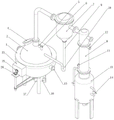
Fig. 1 is a perspective view of the present invention.
Fig. 2 is a perspective view angle two of the present invention.
Fig. 3 is a perspective view angle three of the present invention.
Fig. 4 is a front view of the present invention.
Fig. 5 is a cross-sectional view of a front view of the present invention.
Fig. 6 is a perspective view of the structure within the jacket of the present invention.
Fig. 7 is a perspective view of a driving plate and a reciprocating plate in a jacket according to the present invention.
Fig. 8 is a perspective view of the power transmission device of the present invention with a part of the case removed.
Fig. 9 is a perspective view of a part of the structure of the power transmission device of the present invention.
Fig. 10 is a first process view of the engagement of the drive pin and the drive lever in the power transmission device of the present invention.
Fig. 11 is a second process view of the engagement of the drive pin and the drive lever in the power transmission device of the present invention.
Fig. 12 is a third process diagram of the engagement of the drive pin and the drive lever in the power transmission device of the present invention.
In the figure, 1, a jacket; 2. an inner container; 3. an interlayer; 4. a feed inlet; 5. a vacuum gauge interface; 6. a thermometer interface; 7. a gas-liquid separator; 8. a condenser; 9. a return line; 10. a straight gas angle port; 11. a cooling water inlet; 12. a cooling water outlet; 13. a liquid receiving tank; 14. a vacuum interface; 15. a steam inlet; 16. a condensed water outlet; 17. a liquid discharging pipe; 18. a valve; 19. a rotating shaft; 20. a drive plate; 21. a reciprocating plate; 22. a poking plate; 23. a box body; 24. a drive plate; 25. a first bevel gear; 26. a second bevel gear; 27. a spur gear; 28. a disc; 29. a drive rod; 30. a drive pin; 31. a drive motor; 32. a vent hole.
Detailed Description
The following description of the present invention will be made in further detail with reference to the accompanying drawings 1 to 12.
In the first embodiment, we provide a spherical concentrator, which is improved on the existing spherical concentrator, and includes a support, and is characterized in that a hemispherical jacket 1 is installed on the support, a hollow spherical liner 2 is installed in the jacket 1, the radians of the spherical liner 2 and the hemispherical jacket 1 are matched, an interlayer 3 is formed between the jacket 1 and the liner 2 support, a feed port 4, a vacuum meter interface 5 and a thermometer interface 6 are arranged on the liner 2, the feed port 4 is used for placing materials, the vacuum meter interface 5 is connected with a vacuum meter and used for measuring the air pressure in the liner 2, the upper end of the liner 2 is connected with an air-liquid separator 7 through a pipeline, the right end of the air-liquid separator 7 is connected with a condenser 8 through a pipeline, a return pipeline 9 is communicated between the lower end of the air-liquid separator 7 and the liner 2, a straight air-angle port 10 is arranged on the return pipeline 9, the straight gas corner port 10 is used for preventing gas from entering the gas-liquid separator 7 from the backflow pipeline 9, liquid is arranged in the pipeline and is used for preventing gas from passing through the gas-liquid separator 7 and enabling the liquid to flow back, the condenser 8 is respectively provided with a cooling water inlet 11 and a cooling water outlet 12, the cooling water inlet 11 and the cooling water outlet 12 are communicated with a cooling water cooling device, the lower end of the condenser 8 is communicated with a liquid receiving tank 13, the liquid receiving tank 13 is provided with the straight gas corner port 10 and a vacuum interface 14, the vacuum interface 14 is used for being connected with a vacuum pump and used for performing vacuum air extraction treatment on the inner container 2, and valves 18 are arranged on corresponding pipelines and used for controlling the opening and closing states of the pipelines at various positions;
the steam-assisted air-entrapping device is characterized in that a steam inlet 15 communicated with the interlayer 3 is respectively arranged at the end part of the jacket 1, the steam inlet 15 is connected with a steam heating system to realize steam-entrapping treatment in the interlayer 3, a condensate outlet 16 is arranged at the lower end of the jacket 1, a liquid discharging pipe 17 penetrating through the lower end of the jacket 1 is connected to the lower end of the liner 2, a valve 18 is arranged on the liquid discharging pipe 17, a rotating shaft 19 is rotatably connected outside the liquid discharging pipe 17, the rotating shaft 19 is rotatably connected with the lower end of the jacket 1, an arc-shaped driving plate 20 which is arranged in the interlayer 3 and has an arc-shaped matching radian with the arc of the jacket 1 is arranged on the rotating shaft 19, the distance between the driving plate 20 and the inner side wall of the jacket 1 is 5-10mm, a plurality of groups of vent holes 32 are uniformly distributed on the driving plate 20 along the arc-shaped radian direction, the vent holes 32 are used for exchanging gas, and the outer side of the driving plate 20 is arranged close to the inner side wall of the jacket 1, the jacket 1 is longitudinally and rotatably connected with a reciprocating plate 21 between a driving plate 20 and the outer side wall of the liner 2, the reciprocating plate 21 consists of two groups of hemispherical poking plates 22, the two groups of poking plates 22 are vertically arranged, the radian of the poking plates 22 is consistent with that of the liner 2, the distance between the poking plates 22 and the outer side wall of the liner 2 is 5-10mm, the rotating shaft 19 is driven to rotate by a driving device arranged on the support, the rotating shaft 19 is connected with a rotating shaft of the reciprocating plate 21 through a power transmission device, the rotating shaft 19 drives the reciprocating plate 21 to reciprocate through the power transmission device, the upward driving limit position of the poking plate 22 is positioned above the steam inlet 15, the poking plate 22 is ensured to poke the steam entering the interlayer 3 from the steam inlet 15 downwards, and the driving device is electrically connected with a controller arranged on the support, the driving device comprises a driving motor 31 arranged on a support, an output shaft of the driving motor 31 is in transmission connection with a rotating shaft 19 through a belt, the driving motor 31 is electrically connected with a controller, the controller is made of an integrated CPU and is made of an electronic chip, details are not repeated in the prior art, when the driving device is used, after the whole device is installed, a steam inlet 15 is connected with a steam heating system, liquid is put into an inner container 2, the inlet is sealed, an outlet and an inlet of a condenser 8 are connected with cooling water, meanwhile, a vacuum pump is used for pumping vacuum in the inner container 2, then heating steam is input into the steam inlet 15, then the driving motor 31 is started, the driving motor 31 drives the rotating shaft 19 to rotate, 20 circumferentially rotates along the rotating shaft, the driving plate circumferentially exchanges in an interlayer 3 and simultaneously drives a reciprocating plate 21 to rotate and swing through a power transmission device, carry out decurrent and ascending reciprocating swing to the steam of 15 departments of steam inlet, combine circumferential direction's drive plate 20, make steam in the intermediate layer 3 exchange along circumference and upper and lower direction, stir the below with the hot steam of upside, the lower steam drive of temperature of below arrives the top, heat exchange in the intermediate layer 3 with higher speed, combine drive plate 20 simultaneously to make the heat can transmit the liquid in inner bag 2 fast, the upper and lower of inner bag 2 is heated evenly, this embodiment can carry out the even heating to inner bag 2, upper and lower layer heat exchange is quick in the intermediate layer 3, the heating effect is good, therefore, the clothes hanger is strong in practicability, and is suitable for being generalized to use.
In the second embodiment, on the basis of the first embodiment, the present embodiment discloses a power transmission device, which includes a box 23 installed outside the jacket 1, a driving disk 24 is longitudinally and rotatably connected in the box 23, a first bevel gear 25 disposed on the front side outside the box 23 is coaxially installed on the driving disk 24, and further includes a second bevel gear 26 vertically and rotatably connected outside the jacket 1 and engaged with the first bevel gear 25, the bevel gears serve to change the power direction, the second bevel gear 26 is in transmission connection with the rotating shaft 19 through a belt, two sets of straight gears 27 engaged with each other are longitudinally and rotatably connected in the box 23, the straight gears 27 are rotatably connected to the side walls corresponding to the rotational connection of the driving disk 24, the midpoint of the connecting line of the centers of the rotating shafts of the two sets of straight gears 27 and the axial center of the driving disk 24 are on the same longitudinal straight line, two groups of straight gears 27 are centrosymmetric, the straight gears 27 are coaxially provided with disks 28 arranged between the driving disks 24 and the straight gears 27, the diameters of the disks 28 are smaller than the straight gears 27, the outer edges of the disks 28 are tangentially provided with driving rods 29, the driving rods 29 on the two groups of disks 28 are arranged in central symmetry, the driving disks 24 are provided with driving pins 30 which are contacted and matched with the driving disks 24 to realize pushing, the rotating shafts of one group of straight gears 27 are coaxially connected with the rotating shaft of the reciprocating plate 21, in the embodiment, when the driving disks 24 are driven to rotate by the bevel gear sets, the driving pins 30 on the driving disks 24 push the driving rods 29 on one group of disks 28 to rotate along the rotating shaft of the straight gears 27, due to the meshing of the straight gears 27, the driving rods 29 on the other group of disks 28 reversely rotate, and due to the eccentric arrangement of the centers of the rotating shafts of the disks 28, after the driving pin 30 is separated from the driving rod 29 on one disc 28, the driving pin 30 drives the driving rod 29 on the other disc 28 to rotate along with the rotation of the driving disc 24, and the rotation of the rotating shaft of one group of spur gears 27 is driven to rotate in a reciprocating manner to achieve the effect of reciprocating driving.
When the invention is used, after the whole device is installed, the steam inlet 15 is connected with a steam heating system, after liquid is put into the inner container 2, the inlet is sealed, the outlet and the inlet of the condenser 8 are connected with cooling water, simultaneously, the vacuum pump is utilized to extract vacuum in the inner container 2, then heating steam is input into the steam inlet 15, then the driving motor 31 is started, the driving motor 31 drives the rotating shaft 19 to rotate, the driving plate 20 circumferentially rotates along the rotating shaft, the steam is circumferentially exchanged in the interlayer 3, simultaneously, the rotating shaft 19 drives the driving plate 24 to rotate through the bevel gear group, the driving pin 30 on the driving plate 24 drives the driving rod 29 on one disc 28 to rotate along the rotating shaft of the spur gear 27, due to the meshing of the spur gear 27, the driving rod 29 on the other disc 28 reversely rotates, and due to the eccentric arrangement of the center of the rotating shaft of the disc 28, after the driving pin 30 is separated from the driving rod 29 on one disc 28 for pushing, the driving pin 30 drives the driving rod 29 on the other disc 28 to rotate along with the rotation of the driving disc 24, and the reciprocating swing of the spur gear 27 drives the reciprocating plate 21 to reciprocate in the interlayer 3 so as to reciprocate the steam at the steam inlet 15 downwards and upwards, and the steam in the interlayer 3 exchanges along the circumferential direction and the up-and-down direction by combining the driving plate 20 rotating in the circumferential direction, so that the hot steam at the upper side is shifted to the lower side, the steam with lower temperature at the lower side is driven to the upper side, the heat exchange in the interlayer 3 is accelerated, meanwhile, the heat can be rapidly transferred to the liquid in the inner container 2 by combining the driving plate 20, the upper part and the lower part of the inner container 2 are uniformly heated, and the invention can uniformly heat the inner container 2, the heat exchange of the upper layer and the lower layer in the interlayer 3 is quick, the heating effect is good, the practicability is high, and the heat exchange device is suitable for popularization and use.
The above description is only for the purpose of illustrating the preferred embodiments of the present invention and is not to be construed as limiting the invention, and any modifications, equivalents, improvements and the like that fall within the spirit and principle of the present invention are intended to be included therein.
Claims (7)
1. The spherical concentrator comprises a bracket and is characterized in that a hemispherical jacket (1) is mounted on the bracket, a hollow spherical inner container (2) is mounted in the jacket (1), an interlayer (3) is formed between the jacket (1) and the inner container (2) bracket, a feed inlet (4), a vacuum meter interface (5) and a thermometer interface (6) are arranged on the inner container (2), the upper end of the inner container (2) is connected with a gas-liquid separator (7) through a pipeline, the right end of the gas-liquid separator (7) is communicated with a condenser (8) through a pipeline, a return pipeline (9) is communicated between the lower end of the gas-liquid separator (7) and the inner container (2), a straight gas corner port (10) is arranged on the return pipeline (9), a cooling water inlet (11) and a cooling water outlet (12) are respectively arranged on the condenser (8), the lower end of the condenser (8) is communicated with a liquid receiving tank (13), the liquid receiving tank (13) is provided with a straight gas angle port (10) and a vacuum interface (14);
the steam heating jacket is characterized in that a steam inlet (15) communicated with the interlayer (3) is respectively arranged at the end part of the jacket (1), the steam inlet (15) is connected with a steam heating system, a condensate outlet (16) is arranged at the lower end of the jacket (1), a liquid discharging pipe (17) penetrating through the lower end of the jacket (1) is connected at the lower end of the liner (2), a valve (18) is arranged on the liquid discharging pipe (17), a rotating shaft (19) is rotatably connected outside the liquid discharging pipe (17), the rotating shaft (19) is rotatably connected with the lower end of the jacket (1), an arc-shaped driving plate (20) which is arranged in the interlayer (3) and has an arc-shaped matching degree with the arc of the jacket (1) is arranged on the rotating shaft (19), the outer side of the driving plate (20) is arranged close to the inner side wall of the jacket (1), and the jacket (1) is longitudinally rotatably connected with a reciprocating plate (21) between the driving plate (20) and the outer side wall of the liner (2), reciprocating plate (21) comprise two sets of hemispherical stirring board (22), and two sets of stirring board (22) set up perpendicularly, axis of rotation (19) are rotated through the drive arrangement drive of installing on the support, be connected through power transmission between the pivot of axis of rotation (19) and reciprocating plate (21), satisfy axis of rotation (19) through the reciprocal swing of power transmission drive reciprocating plate (21), electric connection between drive arrangement and the controller of installing on the support.
2. The spherical concentrator according to claim 1, wherein the power transmission device comprises a box (23) installed outside the jacket (1), a driving disk (24) is longitudinally and rotatably connected in the box (23), a first bevel gear (25) disposed on the front side outside the box (23) is coaxially installed on the driving disk (24), a second bevel gear (26) vertically and rotatably connected outside the jacket (1) and engaged with the first bevel gear (25) is further included, the second bevel gear (26) is in transmission connection with the rotating shaft (19) through a belt, two sets of spur gears (27) engaged with each other are longitudinally and rotatably connected in the box (23), the midpoint of the connecting line of the centers of the rotating shafts of the two sets of spur gears (27) and the axial center of the driving disk (24) are in a longitudinal straight line, a disk (28) disposed between the driving disk (24) and the spur gears (27) is coaxially installed on the spur gears (27), the diameter of the disc (28) is smaller than that of the straight gear (27), driving rods (29) are arranged on the outer edge of the disc (28) in the tangential direction, the driving rods (29) on the two groups of discs (28) are arranged in a centrosymmetric mode, driving pins (30) which are in contact fit with the driving disc (24) to achieve pushing are arranged on the driving disc (24), and the rotating shaft of one group of straight gears (27) is coaxially connected with the rotating shaft of the reciprocating plate (21).
3. The concentrator as claimed in claim 1, wherein the drive means comprises a drive motor (31) mounted on a support, an output shaft of the drive motor (31) is in transmission connection with the rotating shaft (19) via a belt, and the drive motor (31) is electrically connected with the controller.
4. The concentrator as claimed in claim 1 wherein the drive plate (20) has a plurality of sets of ventilation holes (32) uniformly distributed along the arc of the arc.
5. Concentrator in spherical form according to claim 1, characterized in that the distance between the drive plate (20) and the inner side wall of the jacket (1) is 5-10 mm.
6. The spherical concentrator according to claim 1, wherein the extreme position of upward actuation of the toggle plate (22) is located above the steam inlet (15).
7. The concentrator as claimed in claim 1, wherein the arc of the driving plate (22) is identical to the arc of the inner container (2), and the distance between the driving plate (22) and the outer wall of the inner container (2) is 5-10 mm.
Priority Applications (1)
| Application Number | Priority Date | Filing Date | Title |
|---|---|---|---|
| CN202210668809.6A CN115025507A (en) | 2022-06-14 | 2022-06-14 | Ball type concentrator |
Applications Claiming Priority (1)
| Application Number | Priority Date | Filing Date | Title |
|---|---|---|---|
| CN202210668809.6A CN115025507A (en) | 2022-06-14 | 2022-06-14 | Ball type concentrator |
Publications (1)
| Publication Number | Publication Date |
|---|---|
| CN115025507A true CN115025507A (en) | 2022-09-09 |
Family
ID=83124171
Family Applications (1)
| Application Number | Title | Priority Date | Filing Date |
|---|---|---|---|
| CN202210668809.6A Pending CN115025507A (en) | 2022-06-14 | 2022-06-14 | Ball type concentrator |
Country Status (1)
| Country | Link |
|---|---|
| CN (1) | CN115025507A (en) |
Citations (4)
| Publication number | Priority date | Publication date | Assignee | Title |
|---|---|---|---|---|
| CN210612903U (en) * | 2019-08-23 | 2020-05-26 | 贵州苗药药业有限公司 | Novel ball-type concentrator is used in medicine subsides production |
| CN213376329U (en) * | 2020-09-27 | 2021-06-08 | 株洲市神农动物药业有限公司 | Agitating unit is used in animal drug manufacturing |
| CN213942850U (en) * | 2020-11-26 | 2021-08-13 | 北京健生饮料有限公司 | Cold and hot jar is used in dairy products preparation |
| CN214548942U (en) * | 2021-01-25 | 2021-11-02 | 浙江绍兴苏泊尔生活电器有限公司 | Stirring rake and cooking utensil |
-
2022
- 2022-06-14 CN CN202210668809.6A patent/CN115025507A/en active Pending
Patent Citations (4)
| Publication number | Priority date | Publication date | Assignee | Title |
|---|---|---|---|---|
| CN210612903U (en) * | 2019-08-23 | 2020-05-26 | 贵州苗药药业有限公司 | Novel ball-type concentrator is used in medicine subsides production |
| CN213376329U (en) * | 2020-09-27 | 2021-06-08 | 株洲市神农动物药业有限公司 | Agitating unit is used in animal drug manufacturing |
| CN213942850U (en) * | 2020-11-26 | 2021-08-13 | 北京健生饮料有限公司 | Cold and hot jar is used in dairy products preparation |
| CN214548942U (en) * | 2021-01-25 | 2021-11-02 | 浙江绍兴苏泊尔生活电器有限公司 | Stirring rake and cooking utensil |
Similar Documents
| Publication | Publication Date | Title |
|---|---|---|
| CN107764106B (en) | A kind of rotation blade heat exchanger | |
| CN106063998B (en) | MVR systems are rotated in a kind of single tank | |
| CN106732074A (en) | A kind of rotary drum stirs tack producing device | |
| CN205868151U (en) | Sealed gluey dispenser of compound multi -direction stirring | |
| CN206459543U (en) | A kind of heat exchanger | |
| CN115025507A (en) | Ball type concentrator | |
| CN210612903U (en) | Novel ball-type concentrator is used in medicine subsides production | |
| CN207095341U (en) | A kind of good jacketed type exchanger of heat exchange property | |
| CN106110988A (en) | The fluid sealant disperse system of compound multi-direction stirring | |
| CN112354199A (en) | Single-effect external circulation concentrator based on electric heating | |
| CN207317432U (en) | Single cone helical vacuum drying machine | |
| CN206199288U (en) | A kind of high-efficiency polymerization kettle for benzoyl area kind product | |
| CN211677605U (en) | Chemical product agitating unit | |
| CN210674250U (en) | Two-effect vacuum concentration device | |
| CN211477817U (en) | Planetary rotary vacuum concentration system | |
| KR100754978B1 (en) | Rotary type concentrating apparatus with round coil | |
| CN204107063U (en) | Fish protein water vacuum decker | |
| CN210097661U (en) | Chemical modification device for ultra-high molecular weight polyethylene powder | |
| CN209098229U (en) | Dyeing and printing sewage processing equipment | |
| CN207576400U (en) | A kind of reaction kettle | |
| CN112503860A (en) | Rotary vacuum drying equipment for processing traditional Chinese medicinal materials | |
| CN107638864B (en) | A kind of temp.-regulating type chemical reaction device | |
| CN206730591U (en) | Deaeration kettle is used in a kind of epoxy pouring sealant production | |
| CN206500087U (en) | A kind of rotary drum stirs tack producing device | |
| CN207085911U (en) | A kind of electric heating reacting kettle |
Legal Events
| Date | Code | Title | Description |
|---|---|---|---|
| PB01 | Publication | ||
| PB01 | Publication | ||
| SE01 | Entry into force of request for substantive examination | ||
| SE01 | Entry into force of request for substantive examination |