CN114991571A - Lifting method for large water tank of emergency water tower - Google Patents
Lifting method for large water tank of emergency water tower Download PDFInfo
- Publication number
- CN114991571A CN114991571A CN202210765192.XA CN202210765192A CN114991571A CN 114991571 A CN114991571 A CN 114991571A CN 202210765192 A CN202210765192 A CN 202210765192A CN 114991571 A CN114991571 A CN 114991571A
- Authority
- CN
- China
- Prior art keywords
- ring beam
- water tank
- lifting
- platform
- main ring
- Prior art date
- Legal status (The legal status is an assumption and is not a legal conclusion. Google has not performed a legal analysis and makes no representation as to the accuracy of the status listed.)
- Withdrawn
Links
Images


Classifications
-
- E—FIXED CONSTRUCTIONS
- E04—BUILDING
- E04H—BUILDINGS OR LIKE STRUCTURES FOR PARTICULAR PURPOSES; SWIMMING OR SPLASH BATHS OR POOLS; MASTS; FENCING; TENTS OR CANOPIES, IN GENERAL
- E04H12/00—Towers; Masts or poles; Chimney stacks; Water-towers; Methods of erecting such structures
- E04H12/34—Arrangements for erecting or lowering towers, masts, poles, chimney stacks, or the like
-
- E—FIXED CONSTRUCTIONS
- E04—BUILDING
- E04G—SCAFFOLDING; FORMS; SHUTTERING; BUILDING IMPLEMENTS OR AIDS, OR THEIR USE; HANDLING BUILDING MATERIALS ON THE SITE; REPAIRING, BREAKING-UP OR OTHER WORK ON EXISTING BUILDINGS
- E04G3/00—Scaffolds essentially supported by building constructions, e.g. adjustable in height
- E04G3/24—Scaffolds essentially supported by building constructions, e.g. adjustable in height specially adapted for particular parts of buildings or for buildings of particular shape, e.g. chimney stacks or pylons
- E04G3/243—Scaffolds essentially supported by building constructions, e.g. adjustable in height specially adapted for particular parts of buildings or for buildings of particular shape, e.g. chimney stacks or pylons following the outside contour of a building
-
- E—FIXED CONSTRUCTIONS
- E04—BUILDING
- E04G—SCAFFOLDING; FORMS; SHUTTERING; BUILDING IMPLEMENTS OR AIDS, OR THEIR USE; HANDLING BUILDING MATERIALS ON THE SITE; REPAIRING, BREAKING-UP OR OTHER WORK ON EXISTING BUILDINGS
- E04G5/00—Component parts or accessories for scaffolds
-
- E—FIXED CONSTRUCTIONS
- E04—BUILDING
- E04G—SCAFFOLDING; FORMS; SHUTTERING; BUILDING IMPLEMENTS OR AIDS, OR THEIR USE; HANDLING BUILDING MATERIALS ON THE SITE; REPAIRING, BREAKING-UP OR OTHER WORK ON EXISTING BUILDINGS
- E04G5/00—Component parts or accessories for scaffolds
- E04G5/04—Means for fastening, supporting, or bracing scaffolds on or against building constructions
- E04G5/041—Means for fastening, supporting, or bracing scaffolds on or against building constructions for fastening scaffolds on roof frameworks or on roofs
-
- E—FIXED CONSTRUCTIONS
- E04—BUILDING
- E04G—SCAFFOLDING; FORMS; SHUTTERING; BUILDING IMPLEMENTS OR AIDS, OR THEIR USE; HANDLING BUILDING MATERIALS ON THE SITE; REPAIRING, BREAKING-UP OR OTHER WORK ON EXISTING BUILDINGS
- E04G5/00—Component parts or accessories for scaffolds
- E04G5/14—Railings
-
- E—FIXED CONSTRUCTIONS
- E04—BUILDING
- E04G—SCAFFOLDING; FORMS; SHUTTERING; BUILDING IMPLEMENTS OR AIDS, OR THEIR USE; HANDLING BUILDING MATERIALS ON THE SITE; REPAIRING, BREAKING-UP OR OTHER WORK ON EXISTING BUILDINGS
- E04G5/00—Component parts or accessories for scaffolds
- E04G5/16—Struts or stiffening rods, e.g. diagonal rods
-
- E—FIXED CONSTRUCTIONS
- E04—BUILDING
- E04H—BUILDINGS OR LIKE STRUCTURES FOR PARTICULAR PURPOSES; SWIMMING OR SPLASH BATHS OR POOLS; MASTS; FENCING; TENTS OR CANOPIES, IN GENERAL
- E04H12/00—Towers; Masts or poles; Chimney stacks; Water-towers; Methods of erecting such structures
- E04H12/30—Water-towers
-
- E—FIXED CONSTRUCTIONS
- E04—BUILDING
- E04H—BUILDINGS OR LIKE STRUCTURES FOR PARTICULAR PURPOSES; SWIMMING OR SPLASH BATHS OR POOLS; MASTS; FENCING; TENTS OR CANOPIES, IN GENERAL
- E04H12/00—Towers; Masts or poles; Chimney stacks; Water-towers; Methods of erecting such structures
- E04H12/34—Arrangements for erecting or lowering towers, masts, poles, chimney stacks, or the like
- E04H12/342—Arrangements for stacking tower sections on top of each other
-
- E—FIXED CONSTRUCTIONS
- E04—BUILDING
- E04G—SCAFFOLDING; FORMS; SHUTTERING; BUILDING IMPLEMENTS OR AIDS, OR THEIR USE; HANDLING BUILDING MATERIALS ON THE SITE; REPAIRING, BREAKING-UP OR OTHER WORK ON EXISTING BUILDINGS
- E04G5/00—Component parts or accessories for scaffolds
- E04G2005/008—Hoisting devices specially adapted as part of a scaffold system
-
- Y—GENERAL TAGGING OF NEW TECHNOLOGICAL DEVELOPMENTS; GENERAL TAGGING OF CROSS-SECTIONAL TECHNOLOGIES SPANNING OVER SEVERAL SECTIONS OF THE IPC; TECHNICAL SUBJECTS COVERED BY FORMER USPC CROSS-REFERENCE ART COLLECTIONS [XRACs] AND DIGESTS
- Y02—TECHNOLOGIES OR APPLICATIONS FOR MITIGATION OR ADAPTATION AGAINST CLIMATE CHANGE
- Y02E—REDUCTION OF GREENHOUSE GAS [GHG] EMISSIONS, RELATED TO ENERGY GENERATION, TRANSMISSION OR DISTRIBUTION
- Y02E10/00—Energy generation through renewable energy sources
- Y02E10/20—Hydro energy
Abstract
The invention relates to the technical field of water tower and water tank installation, in particular to a lifting method for a large water tank of an accident water tower, which comprises the following steps that a plurality of concrete supporting upright posts are arranged on the top surface of a tower body of the water tower, and meanwhile, a single-ring beam hoisting operation platform is manufactured on the ground; hoisting a single-ring beam hoisting operation platform to the upper end of the water tower, and welding and fixing a connecting upright column at the lower end of the operation platform and an embedded plate on a concrete supporting upright column; fixing a through hydraulic jack on the main ring beam, penetrating the prestressed steel strand through the through hydraulic jack and the water tank, and anchoring the prestressed steel strand on the water tank by using a steel strand anchorage device; tensioning the steel strand, and intensively controlling a through hydraulic jack by a hydraulic pump station to realize the integral synchronous lifting of the water tank; according to the invention, the water tank is synchronously lifted by the single ring beam lifting operation platform and the center type hydraulic jack controlled by the hydraulic pump station, so that the ring beam manufacturing cost is saved, the construction steps of multiple lifting are reduced, and the construction efficiency is improved.
Description
Technical Field
The invention relates to the technical field of water tower and water tank installation, in particular to a method for lifting a large water tank of an accident water tower.
Background
With the continuous improvement of smelting technology and scale and the improvement of the water storage capacity of the accident water tower, the accident water tower of each steel mill is generally designed to be about 1000m at present 3 The total monomer amount of the water tank of the inverted cone water tower is about 700t, the design elevation of the water tank is about 30m, the construction measures of erecting a scaffold on the ground to support a template are high in cost, high in safety risk and long in construction period.
In the construction method for lifting the large-scale accident water tower reservoir with the application number of CN202011621266.X, a jack is fixed on a lower ring beam by manufacturing a double-layer ring beam, an upper ring beam is jacked up, and a water tank is indirectly lifted by the upper ring beam; in practical application, the applicant finds that the ring beams of the water tank can not be used universally without different volumes of the water tanks in projects, the water tank has larger volume, the cost for manufacturing the double ring beams is higher, the ring beams can not be reused, and the construction cost is increased; meanwhile, the operation platform needs to be hoisted and fixed by the crane twice, the installation period is long, and the construction efficiency is low.
Disclosure of Invention
The invention aims to solve the problems, and provides a lifting method of a large water tank of an accident water tower, which can reduce the construction cost and improve the construction efficiency.
The invention solves the problems and adopts the technical scheme that:
a method for lifting a large water tank of an accident water tower comprises the following steps,
s1: the top surface of the tower body of the water tower protrudes out of a plurality of concrete supporting upright columns which are symmetrically arranged relative to the center of the top surface of the tower body, and pre-embedded plates are pre-embedded on the concrete supporting upright columns; meanwhile, a single-ring beam hoisting operation platform is manufactured on the ground, and the single-ring beam hoisting operation platform comprises a main ring beam platform and a connecting upright post welded below the main ring beam platform;
s2: hoisting the single-ring beam hoisting operation platform to the upper end of the water tower by using a crane, and welding and fixing the connecting upright column and the embedded plate on the concrete supporting upright column;
s3: fixing N through hydraulic jacks on the main ring beam, wherein the N through hydraulic jacks are symmetrically arranged along the circumference of the main ring beam platform about the center of the main ring beam platform, the N through hydraulic jacks are controlled by the same hydraulic pump station, a prestressed steel strand penetrates through the through hydraulic jacks and the water tank from top to bottom, and the prestressed steel strand is anchored and fixed on the water tank by a steel strand anchorage device, wherein the through hydraulic jacks have a hydraulic self-locking function and are controlled by the same hydraulic pump station and are double-acting synchronous hydraulic jacks;
s4: and tensioning the steel strands one by using the through hydraulic jack, and then, intensively controlling the through hydraulic jack by using a hydraulic pump station to lift the steel strands so as to realize the integral synchronous lifting of the water tank.
Compared with the prior art, the invention adopting the technical scheme has the outstanding characteristics that:
according to the invention, the water tank is synchronously lifted by the single-ring-beam hoisting operation platform and the N through hydraulic jacks controlled by the same hydraulic pump station, so that the ring beam manufacturing cost is saved, the construction steps of multiple hoisting are reduced, and the construction efficiency is improved; can the large-scale water tank of remote control hydraulic power unit promotion, promote construction safety nature.
Preferably, the further technical scheme of the invention is as follows:
the concrete support columns and the connecting columns are respectively provided with 2N, each concrete support column is provided with one connecting column, the inner sides of the connecting columns are connected with tie beams, and the other ends of the tie beams are tied on manhole shafts of the water towers; each two connecting upright columns form a group, and a through hydraulic jack is arranged at the middle position of each group of connecting upright columns on the main ring beam platform; the force of the feed-through hydraulic jack is more stable.
Reinforcing ribs are connected between the connecting upright columns and the adjacent connecting upright columns, the reinforcing ribs are of X-shaped structures, and the end parts of the reinforcing ribs are fixed on the side surfaces of the connecting upright columns through lug plates and bolts; the supporting effect is enhanced.
The main ring beam platform comprises a main ring beam, an inner support is arranged in the main ring beam, a steel plate platform is arranged on the inner support, and a protective railing is arranged on the upper side of the ring beam.
Drawings
Fig. 1 is a schematic structural diagram of a method for lifting a large water tank of an emergency water tower according to an embodiment of the present invention;
fig. 2 is a schematic structural diagram of another method for lifting a large water tank of an emergency water tower according to an embodiment of the present invention;
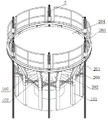
FIG. 3 is a schematic structural diagram of a single-ring beam hoisting operation platform according to an embodiment of the invention;
fig. 4 is a schematic top view of the single-ring beam hoisting operation platform according to the embodiment of the present invention.
In the figure: 1. a water tower; 101. concrete supporting columns; 102. a manhole; 2. hoisting the operating platform by the single ring beam; 201. a main ring beam; 202. connecting the upright posts; 203. a guard rail; 204. a steel plate platform; 205. reinforcing ribs; 206. an inner support; 207. a tie beam; 3. a feed-through hydraulic jack; 4. steel strand wires; 5. a water tank; 6. a steel strand anchor.
Detailed Description
The invention will be further illustrated by the following examples, which are intended only for a better understanding of the present invention and therefore do not limit the scope of the invention.
As shown in fig. 1 to 4, a method for lifting a large water tank of an accident water tower comprises the following steps,
s1: 2N concrete supporting columns 101 (supporting columns when the original tower body is poured) protrude from the tower top surface of the tower body of the water tower 1, in the embodiment, 12 concrete supporting columns 101 are arranged, the 12 concrete supporting columns 101 are symmetrically arranged relative to the center of the top surface of the tower body, and pre-embedded plates 1012 are pre-embedded on the concrete supporting columns 101;
while pouring the water tower 1, manufacturing a single-ring beam hoisting operation platform 2 on the ground, wherein the single-ring beam hoisting operation platform 2 comprises a main ring beam platform and a connecting upright column 202 welded below the main ring beam platform; each fixed concrete supporting upright 101 is provided with a connecting upright 202, 12 fixed concrete supporting uprights 101 are connected with 12 connecting uprights 202, every two connecting uprights 202 form a group, a through hydraulic jack 3 is arranged in the middle of each group of connecting uprights 202 on the main ring beam platform, and 6 through hydraulic jacks 3 are arranged in total.
In order to enhance the supporting effect, the inner side of each connecting upright column 202 is radially connected with a tie beam 207, and the other end of the tie beam 207 is tied on the manhole 102 of the water tower 1; meanwhile, a reinforcing rib 205 is connected between every two adjacent connecting upright columns 202, the reinforcing rib 205 is of an X-shaped structure, the end part of the reinforcing rib 205 is fixed on the side surface of each connecting upright column 202 through an ear plate and a bolt, and the reinforcing rib 205 can be repeatedly utilized in different construction projects;
further, the connecting upright column 202 is made of H-shaped steel and comprises two parts, namely a vertical part and an inclined supporting part welded on the vertical part and inclined upwards, wherein the upper end of the inclined supporting part is welded and fixed with the lower side of the platform of the main ring beam 201; the lower end of the vertical part is welded and fixed with an embedded part on the concrete supporting upright 101.
The main ring beam platform comprises a main ring beam 201, the outer diameter of the main ring beam 201 is smaller than the inner diameter of the top of the inverted cone-shaped water tank 5 and larger than the inner diameter of the bottom of the inverted cone-shaped water tank 5, an inner support 206 is arranged on the inner side of the main ring beam, the inner support 206 comprises a main support frame arranged in a cross shape and branch supports arranged at 30 degrees, 60 degrees, 120 degrees, 150 degrees, 210 degrees, 240 degrees, 300 degrees and 330 degrees, a steel plate platform 204 is arranged on the inner support 206, a guard rail 203 is arranged on the upper side of the ring beam, and the height of the guard rail 203 is larger than 1.2 m;
s2: hoisting the single-ring beam hoisting operation platform 2 to the upper end of the water tower 1 by using a crane, and welding and fixing the connecting upright column 202 and the embedded plate 1012 on the concrete supporting upright column 101;
s3: the main ring beam 201 is radially close to the connecting upright column 202, 6 penetrating hydraulic jacks 3 are uniformly distributed along the circumference, the 6 penetrating hydraulic jacks 3 are symmetrically distributed along the circumference of the main ring beam platform about the center of the main ring beam platform, the 6 penetrating hydraulic jacks 3 are controlled by the same hydraulic pump station, the prestressed steel strands 4 penetrate through the penetrating hydraulic jacks 3 and the water tank 5 from top to bottom, the water tank 5 is an inverted cone-shaped water tank 5, and the prestressed steel strands 4 are anchored and fixed at the bottom of the water tank 5 by steel strand anchors 6, wherein the penetrating hydraulic jacks 3 have a hydraulic self-locking function, and the 6 penetrating hydraulic jacks 3 are controlled by the same hydraulic pump station and are double-acting synchronous hydraulic jacks;
the hydraulic pump station can be remotely controlled, and the specific synchronous control structure and control method can refer to a computer synchronous controller device and a construction method of integral tensioning with application number CN201110233872.9 or an automatic control system and method of pretensioning prestress construction of CN201610358085. X.
S4: tensioning the steel strands 4 one by using the straight-through hydraulic jacks 3, then intensively controlling the straight-through hydraulic jacks 3 by using a hydraulic pump station, lifting the steel strands 4, controlling the oil pressure at 2-3MPa before lifting, taking 0.5MPa as a first level, gradually increasing the oil supply pressure until the water tank 5 can be lifted, standing for 4-6h after the water tank 5 is lifted to a height of 0.4m away from the ground, checking the height and levelness of the water tank 5, and synchronously lifting the water tank 5 to an installation in-place elevation by 6 straight-through hydraulic jacks 3 after the checking is qualified, and installing.
According to the invention, the water tank 5 is synchronously lifted by the single ring beam hoisting operation platform and the plurality of through hydraulic jacks 3 controlled by the same hydraulic pump station, so that the ring beam manufacturing cost is saved, the construction steps of multiple hoisting are reduced, and the construction efficiency is improved; can remote control hydraulic power unit promote large-scale water tank 5, promote construction safety nature.
The above description is only for the purpose of illustrating the preferred embodiments of the present invention and is not to be construed as limiting the scope of the present invention, which is defined in the appended claims.
Claims (4)
1. A method for lifting a large water tank of an accident water tower is characterized by comprising the following steps: comprises the following steps of (a) carrying out,
s1: the top surface of the tower body of the water tower protrudes out of a plurality of concrete supporting upright columns which are symmetrically arranged relative to the center of the top surface of the tower body, and pre-embedded plates are pre-embedded on the concrete supporting upright columns; meanwhile, a single-ring beam hoisting operation platform is manufactured on the ground, and the single-ring beam hoisting operation platform comprises a main ring beam platform and a connecting stand column welded below the main ring beam platform;
s2: hoisting the single-ring beam hoisting operation platform to the upper end of the water tower by using a crane, and welding and fixing the connecting upright column and the embedded plate on the concrete supporting upright column;
s3: fixing N through hydraulic jacks on the main ring beam, wherein the N through hydraulic jacks are symmetrically arranged along the circumference of the main ring beam platform about the center of the main ring beam platform, the N through hydraulic jacks are controlled by the same hydraulic pump station, a prestressed steel strand penetrates through the through hydraulic jacks and the water tank from top to bottom, and the prestressed steel strand is anchored and fixed on the water tank by a steel strand anchorage device, wherein the through hydraulic jacks have a hydraulic self-locking function and are controlled by the same hydraulic pump station and are double-acting synchronous hydraulic jacks;
s4: and tensioning the steel strands one by using the through hydraulic jack, and then, intensively controlling the through hydraulic jack by using a hydraulic pump station to lift the steel strands so as to realize the integral synchronous lifting of the water tank.
2. The method for lifting the large water tank of the accident water tower according to claim 1, wherein: the concrete support columns and the connecting columns are respectively provided with 2N, each concrete support column is provided with one connecting column, the inner sides of the connecting columns are connected with tie beams, and the other ends of the tie beams are tied on manhole shafts of the water towers; every two connecting upright posts form a group, and a through hydraulic jack is arranged at the middle position of each group of connecting upright posts on the main ring beam platform.
3. The method for lifting the large water tank of the accident water tower according to claim 2, wherein: the reinforcing ribs are connected between the connecting upright columns and the adjacent connecting upright columns, the reinforcing ribs are of X-shaped structures, and the end parts of the reinforcing ribs are fixed on the side surfaces of the connecting upright columns through the lug plates and the bolts.
4. The method for lifting the large water tank of the accident water tower according to claim 2, wherein: the main ring beam platform comprises a main ring beam, an inner support is arranged in the main ring beam, a steel plate platform is arranged on the inner support, and a protective railing is arranged on the upper side of the ring beam.
Priority Applications (1)
| Application Number | Priority Date | Filing Date | Title |
|---|---|---|---|
| CN202210765192.XA CN114991571A (en) | 2022-07-01 | 2022-07-01 | Lifting method for large water tank of emergency water tower |
Applications Claiming Priority (1)
| Application Number | Priority Date | Filing Date | Title |
|---|---|---|---|
| CN202210765192.XA CN114991571A (en) | 2022-07-01 | 2022-07-01 | Lifting method for large water tank of emergency water tower |
Publications (1)
| Publication Number | Publication Date |
|---|---|
| CN114991571A true CN114991571A (en) | 2022-09-02 |
Family
ID=83019183
Family Applications (1)
| Application Number | Title | Priority Date | Filing Date |
|---|---|---|---|
| CN202210765192.XA Withdrawn CN114991571A (en) | 2022-07-01 | 2022-07-01 | Lifting method for large water tank of emergency water tower |
Country Status (1)
| Country | Link |
|---|---|
| CN (1) | CN114991571A (en) |
Citations (5)
| Publication number | Priority date | Publication date | Assignee | Title |
|---|---|---|---|---|
| CN201105971Y (en) * | 2007-10-22 | 2008-08-27 | 天津二十冶建设有限公司 | Steel reinforced concrete water-tower water tank lifting apparatus |
| CN101634197A (en) * | 2009-07-17 | 2010-01-27 | 中冶实久建设有限公司 | Novel construction method for hoisting reverse cone-shape water-tower water tank |
| CN105366598A (en) * | 2015-09-28 | 2016-03-02 | 中国一冶集团有限公司 | Hydraulic lifting method for gas holder top |
| US10995512B1 (en) * | 2020-02-05 | 2021-05-04 | Osmose Utilities Services, Inc. | Temporary support structure |
| CN112814464A (en) * | 2020-12-31 | 2021-05-18 | 广西建工集团第五建筑工程有限责任公司 | Construction method for lifting large-scale accident water tower reservoir |
-
2022
- 2022-07-01 CN CN202210765192.XA patent/CN114991571A/en not_active Withdrawn
Patent Citations (5)
| Publication number | Priority date | Publication date | Assignee | Title |
|---|---|---|---|---|
| CN201105971Y (en) * | 2007-10-22 | 2008-08-27 | 天津二十冶建设有限公司 | Steel reinforced concrete water-tower water tank lifting apparatus |
| CN101634197A (en) * | 2009-07-17 | 2010-01-27 | 中冶实久建设有限公司 | Novel construction method for hoisting reverse cone-shape water-tower water tank |
| CN105366598A (en) * | 2015-09-28 | 2016-03-02 | 中国一冶集团有限公司 | Hydraulic lifting method for gas holder top |
| US10995512B1 (en) * | 2020-02-05 | 2021-05-04 | Osmose Utilities Services, Inc. | Temporary support structure |
| CN112814464A (en) * | 2020-12-31 | 2021-05-18 | 广西建工集团第五建筑工程有限责任公司 | Construction method for lifting large-scale accident water tower reservoir |
Non-Patent Citations (1)
| Title |
|---|
| 江正荣: "《建筑施工工程师手册》", 中国建筑工业出版社, pages: 351 * |
Similar Documents
| Publication | Publication Date | Title |
|---|---|---|
| CN213267529U (en) | Assembled bridge concatenation bent cap installation bearing structure | |
| CN102535845A (en) | Construction method of bearing frame of corridor structure | |
| CN110965470A (en) | Main tower cross brace structure system capable of bearing three-way load and construction method | |
| CN112227232B (en) | Pier upright post underpinning method of pier-beam consolidation continuous beam bridge | |
| CN113550235A (en) | Cast-in-place bent cap support and construction method thereof | |
| CN212053673U (en) | Tower construction operation platform of dome | |
| CN215165629U (en) | Structure for lowering steel cofferdam by utilizing steel pipe pile of drilling platform | |
| CN211772852U (en) | Main tower cross brace structure system capable of bearing three-way load | |
| CN211690792U (en) | Building jacking underpins device | |
| CN219175013U (en) | Whole support that moves down of double-deck overhead bridge | |
| CN112112284A (en) | Integral jacking construction method for net rack | |
| CN114991571A (en) | Lifting method for large water tank of emergency water tower | |
| CN212533734U (en) | Cable buckle integrated tower | |
| CN111576439A (en) | Concrete support dismantling prestressed support and construction method thereof | |
| CN202611250U (en) | Concreting platform for concrete filled steel tube column | |
| CN215168617U (en) | Large-scale accident water tower cistern lifting support | |
| CN112814464A (en) | Construction method for lifting large-scale accident water tower reservoir | |
| CN216973126U (en) | Bridge construction device | |
| CN215714684U (en) | Cast-in-situ bent cap support | |
| CN217128046U (en) | Asymmetric pier supporting platform system device | |
| CN215854863U (en) | Hydraulic lifting device for inverted cone shell water tank | |
| CN217732445U (en) | Double-lifting-point lifting support attached to unequal-height concrete columns | |
| CN213329138U (en) | Loading device and test equipment for foundation pile pulling-resistant static load test | |
| CN218346228U (en) | Steel-pipe pile prefabricated extension basis | |
| CN220058557U (en) | Anti-overturning support column for bearing rail layer basement roof returning |
Legal Events
| Date | Code | Title | Description |
|---|---|---|---|
| PB01 | Publication | ||
| PB01 | Publication | ||
| SE01 | Entry into force of request for substantive examination | ||
| SE01 | Entry into force of request for substantive examination | ||
| WW01 | Invention patent application withdrawn after publication | ||
| WW01 | Invention patent application withdrawn after publication |
Application publication date: 20220902 |