CN114941689A - Rotating device and power transmission device - Google Patents
Rotating device and power transmission device Download PDFInfo
- Publication number
- CN114941689A CN114941689A CN202210022810.1A CN202210022810A CN114941689A CN 114941689 A CN114941689 A CN 114941689A CN 202210022810 A CN202210022810 A CN 202210022810A CN 114941689 A CN114941689 A CN 114941689A
- Authority
- CN
- China
- Prior art keywords
- rotating
- rotating body
- plate
- centrifugal
- cam follower
- Prior art date
- Legal status (The legal status is an assumption and is not a legal conclusion. Google has not performed a legal analysis and makes no representation as to the accuracy of the status listed.)
- Pending
Links
Images


Classifications
-
- F—MECHANICAL ENGINEERING; LIGHTING; HEATING; WEAPONS; BLASTING
- F16—ENGINEERING ELEMENTS AND UNITS; GENERAL MEASURES FOR PRODUCING AND MAINTAINING EFFECTIVE FUNCTIONING OF MACHINES OR INSTALLATIONS; THERMAL INSULATION IN GENERAL
- F16F—SPRINGS; SHOCK-ABSORBERS; MEANS FOR DAMPING VIBRATION
- F16F15/00—Suppression of vibrations in systems; Means or arrangements for avoiding or reducing out-of-balance forces, e.g. due to motion
- F16F15/10—Suppression of vibrations in rotating systems by making use of members moving with the system
- F16F15/12—Suppression of vibrations in rotating systems by making use of members moving with the system using elastic members or friction-damping members, e.g. between a rotating shaft and a gyratory mass mounted thereon
- F16F15/131—Suppression of vibrations in rotating systems by making use of members moving with the system using elastic members or friction-damping members, e.g. between a rotating shaft and a gyratory mass mounted thereon the rotating system comprising two or more gyratory masses
- F16F15/133—Suppression of vibrations in rotating systems by making use of members moving with the system using elastic members or friction-damping members, e.g. between a rotating shaft and a gyratory mass mounted thereon the rotating system comprising two or more gyratory masses using springs as elastic members, e.g. metallic springs
- F16F15/1337—Torsional springs, e.g. torsion bar or torsionally-loaded coil springs
-
- F—MECHANICAL ENGINEERING; LIGHTING; HEATING; WEAPONS; BLASTING
- F16—ENGINEERING ELEMENTS AND UNITS; GENERAL MEASURES FOR PRODUCING AND MAINTAINING EFFECTIVE FUNCTIONING OF MACHINES OR INSTALLATIONS; THERMAL INSULATION IN GENERAL
- F16F—SPRINGS; SHOCK-ABSORBERS; MEANS FOR DAMPING VIBRATION
- F16F15/00—Suppression of vibrations in systems; Means or arrangements for avoiding or reducing out-of-balance forces, e.g. due to motion
- F16F15/10—Suppression of vibrations in rotating systems by making use of members moving with the system
- F16F15/12—Suppression of vibrations in rotating systems by making use of members moving with the system using elastic members or friction-damping members, e.g. between a rotating shaft and a gyratory mass mounted thereon
- F16F15/131—Suppression of vibrations in rotating systems by making use of members moving with the system using elastic members or friction-damping members, e.g. between a rotating shaft and a gyratory mass mounted thereon the rotating system comprising two or more gyratory masses
- F16F15/133—Suppression of vibrations in rotating systems by making use of members moving with the system using elastic members or friction-damping members, e.g. between a rotating shaft and a gyratory mass mounted thereon the rotating system comprising two or more gyratory masses using springs as elastic members, e.g. metallic springs
- F16F15/134—Wound springs
- F16F15/13469—Combinations of dampers, e.g. with multiple plates, multiple spring sets, i.e. complex configurations
-
- F—MECHANICAL ENGINEERING; LIGHTING; HEATING; WEAPONS; BLASTING
- F16—ENGINEERING ELEMENTS AND UNITS; GENERAL MEASURES FOR PRODUCING AND MAINTAINING EFFECTIVE FUNCTIONING OF MACHINES OR INSTALLATIONS; THERMAL INSULATION IN GENERAL
- F16F—SPRINGS; SHOCK-ABSORBERS; MEANS FOR DAMPING VIBRATION
- F16F15/00—Suppression of vibrations in systems; Means or arrangements for avoiding or reducing out-of-balance forces, e.g. due to motion
- F16F15/10—Suppression of vibrations in rotating systems by making use of members moving with the system
- F16F15/14—Suppression of vibrations in rotating systems by making use of members moving with the system using masses freely rotating with the system, i.e. uninvolved in transmitting driveline torque, e.g. rotative dynamic dampers
- F16F15/1407—Suppression of vibrations in rotating systems by making use of members moving with the system using masses freely rotating with the system, i.e. uninvolved in transmitting driveline torque, e.g. rotative dynamic dampers the rotation being limited with respect to the driving means
- F16F15/145—Masses mounted with play with respect to driving means thus enabling free movement over a limited range
-
- F—MECHANICAL ENGINEERING; LIGHTING; HEATING; WEAPONS; BLASTING
- F16—ENGINEERING ELEMENTS AND UNITS; GENERAL MEASURES FOR PRODUCING AND MAINTAINING EFFECTIVE FUNCTIONING OF MACHINES OR INSTALLATIONS; THERMAL INSULATION IN GENERAL
- F16H—GEARING
- F16H25/00—Gearings comprising primarily only cams, cam-followers and screw-and-nut mechanisms
- F16H25/18—Gearings comprising primarily only cams, cam-followers and screw-and-nut mechanisms for conveying or interconverting oscillating or reciprocating motions
- F16H25/183—Gearings comprising primarily only cams, cam-followers and screw-and-nut mechanisms for conveying or interconverting oscillating or reciprocating motions conveying only reciprocating motion, e.g. wedges
-
- F—MECHANICAL ENGINEERING; LIGHTING; HEATING; WEAPONS; BLASTING
- F16—ENGINEERING ELEMENTS AND UNITS; GENERAL MEASURES FOR PRODUCING AND MAINTAINING EFFECTIVE FUNCTIONING OF MACHINES OR INSTALLATIONS; THERMAL INSULATION IN GENERAL
- F16H—GEARING
- F16H41/00—Rotary fluid gearing of the hydrokinetic type
- F16H41/04—Combined pump-turbine units
-
- F—MECHANICAL ENGINEERING; LIGHTING; HEATING; WEAPONS; BLASTING
- F16—ENGINEERING ELEMENTS AND UNITS; GENERAL MEASURES FOR PRODUCING AND MAINTAINING EFFECTIVE FUNCTIONING OF MACHINES OR INSTALLATIONS; THERMAL INSULATION IN GENERAL
- F16H—GEARING
- F16H41/00—Rotary fluid gearing of the hydrokinetic type
- F16H41/24—Details
-
- F—MECHANICAL ENGINEERING; LIGHTING; HEATING; WEAPONS; BLASTING
- F16—ENGINEERING ELEMENTS AND UNITS; GENERAL MEASURES FOR PRODUCING AND MAINTAINING EFFECTIVE FUNCTIONING OF MACHINES OR INSTALLATIONS; THERMAL INSULATION IN GENERAL
- F16H—GEARING
- F16H45/00—Combinations of fluid gearings for conveying rotary motion with couplings or clutches
- F16H45/02—Combinations of fluid gearings for conveying rotary motion with couplings or clutches with mechanical clutches for bridging a fluid gearing of the hydrokinetic type
-
- F—MECHANICAL ENGINEERING; LIGHTING; HEATING; WEAPONS; BLASTING
- F16—ENGINEERING ELEMENTS AND UNITS; GENERAL MEASURES FOR PRODUCING AND MAINTAINING EFFECTIVE FUNCTIONING OF MACHINES OR INSTALLATIONS; THERMAL INSULATION IN GENERAL
- F16F—SPRINGS; SHOCK-ABSORBERS; MEANS FOR DAMPING VIBRATION
- F16F2222/00—Special physical effects, e.g. nature of damping effects
- F16F2222/08—Inertia
-
- F—MECHANICAL ENGINEERING; LIGHTING; HEATING; WEAPONS; BLASTING
- F16—ENGINEERING ELEMENTS AND UNITS; GENERAL MEASURES FOR PRODUCING AND MAINTAINING EFFECTIVE FUNCTIONING OF MACHINES OR INSTALLATIONS; THERMAL INSULATION IN GENERAL
- F16F—SPRINGS; SHOCK-ABSORBERS; MEANS FOR DAMPING VIBRATION
- F16F2232/00—Nature of movement
- F16F2232/02—Rotary
-
- F—MECHANICAL ENGINEERING; LIGHTING; HEATING; WEAPONS; BLASTING
- F16—ENGINEERING ELEMENTS AND UNITS; GENERAL MEASURES FOR PRODUCING AND MAINTAINING EFFECTIVE FUNCTIONING OF MACHINES OR INSTALLATIONS; THERMAL INSULATION IN GENERAL
- F16F—SPRINGS; SHOCK-ABSORBERS; MEANS FOR DAMPING VIBRATION
- F16F2236/00—Mode of stressing of basic spring or damper elements or devices incorporating such elements
- F16F2236/08—Torsion
-
- F—MECHANICAL ENGINEERING; LIGHTING; HEATING; WEAPONS; BLASTING
- F16—ENGINEERING ELEMENTS AND UNITS; GENERAL MEASURES FOR PRODUCING AND MAINTAINING EFFECTIVE FUNCTIONING OF MACHINES OR INSTALLATIONS; THERMAL INSULATION IN GENERAL
- F16H—GEARING
- F16H45/00—Combinations of fluid gearings for conveying rotary motion with couplings or clutches
- F16H45/02—Combinations of fluid gearings for conveying rotary motion with couplings or clutches with mechanical clutches for bridging a fluid gearing of the hydrokinetic type
- F16H2045/0221—Combinations of fluid gearings for conveying rotary motion with couplings or clutches with mechanical clutches for bridging a fluid gearing of the hydrokinetic type with damping means
- F16H2045/0226—Combinations of fluid gearings for conveying rotary motion with couplings or clutches with mechanical clutches for bridging a fluid gearing of the hydrokinetic type with damping means comprising two or more vibration dampers
- F16H2045/0231—Combinations of fluid gearings for conveying rotary motion with couplings or clutches with mechanical clutches for bridging a fluid gearing of the hydrokinetic type with damping means comprising two or more vibration dampers arranged in series
-
- F—MECHANICAL ENGINEERING; LIGHTING; HEATING; WEAPONS; BLASTING
- F16—ENGINEERING ELEMENTS AND UNITS; GENERAL MEASURES FOR PRODUCING AND MAINTAINING EFFECTIVE FUNCTIONING OF MACHINES OR INSTALLATIONS; THERMAL INSULATION IN GENERAL
- F16H—GEARING
- F16H45/00—Combinations of fluid gearings for conveying rotary motion with couplings or clutches
- F16H45/02—Combinations of fluid gearings for conveying rotary motion with couplings or clutches with mechanical clutches for bridging a fluid gearing of the hydrokinetic type
- F16H2045/0221—Combinations of fluid gearings for conveying rotary motion with couplings or clutches with mechanical clutches for bridging a fluid gearing of the hydrokinetic type with damping means
- F16H2045/0263—Combinations of fluid gearings for conveying rotary motion with couplings or clutches with mechanical clutches for bridging a fluid gearing of the hydrokinetic type with damping means the damper comprising a pendulum
Abstract
The present application relates to a rotating device and a power transmission device that suppress foreign matter from adhering to an outer peripheral portion of a first rotating body. A rotating device (10) is provided with a first rotating body (2) and a second rotating body (3). The first rotating body (2) is arranged to be rotatable. The second rotating body (3) is disposed so as to be rotatable together with the first rotating body (2) and so as to be rotatable relative to the first rotating body (2). The second rotating body (3) has a first plate (3a) and a second plate (3 b). The first plate (3a) and the second plate (3b) are configured to form an accommodation space that accommodates the outer peripheral portion (22) of the first rotating body (2).
Description
Technical Field
The present invention relates to a rotating device and a power transmission device.
Background
There is known a rotary device having first and second rotary members capable of relative rotation. A functional member such as a centrifugal piece or a vibrator for functioning as a rotating device is attached to an outer peripheral portion of the first rotating body. An example of such a rotating device is a torque fluctuation suppression device.
For example, in the torque fluctuation suppression device described in patent document 1, the hub flange and the mass body rotate relative to each other. A functional member for exhibiting a torque fluctuation suppression function is attached to an outer peripheral portion of the hub flange. Specifically, a centrifugal member is attached to an outer peripheral portion of the hub flange. When the torque fluctuation suppressing device exhibits the torque fluctuation suppressing function, the centrifugal member moves in the radial direction.
Patent document 1: japanese patent laid-open publication No. 2018-132161
In the torque fluctuation suppression device, when foreign matter such as metal shavings and grits adheres to the outer peripheral portion of the hub flange, there is a possibility that functional components such as the centrifugal member do not smoothly operate and the function of the rotating device is hindered.
Disclosure of Invention
Therefore, the present invention has a technical problem of suppressing the adhesion of foreign matter to the outer peripheral portion of the first rotating portion.
A turning device according to a first aspect of the present invention includes a first turning body and a second turning body. The first rotating body is configured to be rotatable. The second rotating body is disposed so as to be rotatable together with the first rotating body and so as to be rotatable relative to the first rotating body. The second rotating body has a first plate and a second plate. The first plate and the second plate are configured to form an accommodation space that accommodates the outer peripheral portion of the first rotating body.
According to this configuration, the outer peripheral portion of the first rotating body is accommodated in the accommodating space formed by the first plate and the second plate. Therefore, it is possible to suppress the foreign matter from adhering to the outer peripheral portion of the first rotating body. Further, when a functional component or the like attached to the outer peripheral portion of the first rotating body is damaged, the damaged component can be prevented from flying out due to a centrifugal force.
Preferably, the first plate has a first annular portion and a first cylindrical portion. The first cylindrical portion extends in the axial direction from an inner peripheral end portion of the first annular portion toward the second plate. The second plate has a second annular portion and a second cylindrical portion. The second annular portion is disposed at a distance from the first annular portion in the axial direction. The second cylindrical portion extends in the axial direction from an outer peripheral end portion of the second annular portion toward the first plate. According to this configuration, the first plate and the second plate have a symmetrical shape, and therefore the balance of the second rotating body is excellent. Further, the first plate and the second plate have cylindrical portions and are formed in a drawn (drawing) shape, and therefore, are excellent in strength.
Preferably, the first annular portion is disposed with a first gap between an outer peripheral end portion and a front end portion of the second cylindrical portion. With this configuration, foreign matter and the like that intrude into the housing space can be discharged from the first gap.
The first plate may have a first annular portion, a first cylindrical portion, and a second cylindrical portion. Note that the first cylindrical portion extends in the axial direction from the inner peripheral end portion of the first annular portion toward the second plate. The second cylindrical portion extends in the axial direction from the outer peripheral end portion of the first annular portion toward the second plate. The second plate may have a second annular portion arranged at a distance from the first annular portion in the axial direction.
Preferably, the second annular portion is disposed with a second gap between the inner peripheral end portion and the front end portion of the first cylindrical portion.
Preferably, the first rotating body has an inner peripheral portion and a coupling portion. The inner peripheral portion of the first rotating body is disposed outside the accommodating space. The connecting portion connects the outer peripheral portion and the inner peripheral portion through the second gap.
Preferably, the coupling portion has a first bearing surface facing radially inward. The first cylindrical portion has a second support surface facing in the radial direction so as to be supported by the first support surface. According to this configuration, the second rotating body is supported by the first supporting surface via the second supporting surface. The first and second bearing surfaces face in a radial direction. Thus, the second rotating body is positioned radially with respect to the first rotating body. As a result, the eccentric rotation of the second rotating body with respect to the first rotating body can be suppressed.
Preferably, the rotating device further includes a sliding member disposed between the first support surface and the second support surface. With this configuration, wear of the first bearing surface and the second bearing surface can be suppressed.
Preferably, the first rotating member and the second rotating member are plate-shaped. In addition, the first rotating body is thicker than the second rotating body. The sliding member is mounted on the first support surface. According to this configuration, the sliding member is attached to the first rotating body which is thicker than the second rotating body. Therefore, it is advantageous in terms of strength when the sliding member is attached to the first support surface by press-fitting (press-fitting) or when the sliding member attached to the first rotating body is machined.
Preferably, the rotating device is further provided with a spacer. The spacer is disposed between the first rotating body and the second rotating body in the axial direction. According to this configuration, the second rotating body can be prevented from inclining so as to approach the first rotating body.
Preferably, the rotating device is further provided with a centrifugal member configured to be radially movable. The first rotating body has a housing portion that houses the centrifugal member.
Preferably, the centrifugal member is configured to rotate when moving in the radial direction.
Preferably, the rotating device further includes a first rolling member. The accommodating portion has a first guide surface and a second guide surface facing the circumferential direction. The first rolling member is disposed between the first guide surface and the centrifugal member. The first rolling member is configured to roll on the first guide surface by the rotation of the centrifugal member.
Preferably, the centrifugal member is configured to roll on the second guide surface.
Preferably, the centrifugal member and the first rolling member are cylindrical or columnar. The distance between the first guide surface and the second guide surface is smaller than the sum of the diameter of the centrifugal member and the diameter of the first rolling member.
Preferably, the rotating device further includes a cam mechanism. The cam mechanism receives a centrifugal force acting on the centrifugal member, and converts the centrifugal force into a circumferential force in a direction in which the rotational phase difference between the first rotating body and the second rotating body is reduced.
Preferably, the cam mechanism has a cam surface and a cam follower. The cam surface is formed in the eccentric member. The cam follower abuts against the cam surface. The cam follower transmits force between the centrifugal member and the second rotating body.
Preferably, the cam follower rolls on the cam surface.
Preferably, the centrifugal piece has a first through hole that penetrates in the axial direction. The cam surface is formed by an inner wall surface of the first through hole.
Preferably, the cam follower is attached to the second rotating body so as to be rotatable.
Preferably, the second rotating body has a second through hole. The cam follower rolls on the inner wall surface of the second through hole.
Preferably, the cam follower is a cylindrical or cylindrical roller.
Preferably, the rotating device further includes a cylindrical or cylindrical cam follower. The centrifuge has a first through-hole extending in the axial direction. The second rotating body has a second through hole extending in the axial direction. The inner wall surface of the first through hole constitutes a cam surface. The cam surface faces radially outward and abuts the cam follower. The inner wall surface of the second through hole constitutes a contact surface. The contact surface faces radially inward and contacts the cam follower. The cam surface has a first region and a second region. When the centrifugal member rolls on the first guide surface via the first rolling member, the first region abuts against the cam follower. The second region abuts the cam follower when the centrifugal member rolls on the second guide surface. The first region has a curved surface shape different from that of the second region.
Preferably, the first region has a radius of curvature that is less than the radius of curvature of the second region.
Preferably, the abutment surface has a third region and a fourth region. When the centrifugal member rolls on the first guide surface via the first rolling member, the third region abuts against the cam follower. The fourth region abuts the cam follower when the centrifugal member rolls on the second guide surface. The third region has a curved surface shape different from that of the fourth region.
Preferably, the rotating device further includes a cylindrical or cylindrical cam follower. The centrifuge has a first through-hole extending in the axial direction. The second rotating body has a second through hole extending in the axial direction. The inner wall surface of the first through hole constitutes a cam surface. The cam surface faces radially outward and abuts the cam follower. The inner wall surface of the second through hole constitutes a contact surface. The contact surface faces radially inward and contacts the cam follower. The abutment surface has a third region and a fourth region. When the centrifugal member rolls on the first guide surface via the first rolling member, the third region abuts against the cam follower. The fourth region abuts the cam follower when the centrifugal member rolls on the second guide surface. The third region has a curved surface shape different from that of the fourth region.
Preferably, the third region has a radius of curvature greater than a radius of curvature of the fourth region.
Preferably, the rotating device further includes a state maintaining mechanism. The state maintaining mechanism is configured to maintain the state of the centrifugal member so that the boundary between the first region and the second region is in contact with the cam follower when the first rotating body and the second rotating body do not rotate relative to each other but rotate integrally.
Preferably, the state maintaining mechanism includes a first engaging portion formed on the first rotating body and a second engaging portion formed on the centrifugal member and engaged with the first engaging portion.
Preferably, the second rotating body has a restriction groove. The first rolling member is supported by the restricting groove.
Preferably, the receiving portion has a bottom surface and a coupling surface. The bottom surface faces radially outward. The connecting surface connects the first guide surface and the bottom surface.
The connecting surface may be a curved surface or a flat surface.
A power transmission device according to a second aspect of the present invention includes: an input section; an output member that transmits torque from the input member to the output member; and any one of the torque fluctuation suppressing devices described above.
Effects of the invention
According to the present invention, it is possible to suppress foreign matter from adhering to the outer peripheral portion of the first rotating portion.
Drawings
FIG. 1 is a schematic illustration of a torque converter.
Fig. 2 is a front view of the torque fluctuation suppression device with the first plate removed.
Fig. 3 is a sectional view taken along line III-III of fig. 2.
Fig. 4 is an enlarged front view of the torque fluctuation suppression device.
Fig. 5 is a front view of the torque fluctuation suppression device.
Fig. 6 is an enlarged front view of the torque fluctuation suppression device.
Fig. 7 is a schematic diagram showing a positional relationship among the centrifugal element, the cam follower, the inertia ring, and the first rolling member in a state where the input torque does not fluctuate.
Fig. 8 is a schematic diagram showing a positional relationship among the centrifugal element, the cam follower, the inertia ring, and the first rolling member in a state where torque fluctuation is input.
Fig. 9 is a graph showing an example of the characteristics of the torque fluctuation suppression device.
Fig. 10 is a schematic view of a vibration damping device.
Fig. 11 is an enlarged front view of a torque fluctuation suppression device according to a modification example.
Fig. 12 is an enlarged front view of a torque fluctuation suppression device according to a modification example.
Fig. 13 is an enlarged front view of a torque fluctuation suppression device according to a modification.
Fig. 14 is an enlarged front view of a torque fluctuation suppression device according to a modification.
Fig. 15 is an enlarged front view of a torque fluctuation suppression device according to a modification.
Fig. 16 is an enlarged front view of a torque fluctuation suppression device according to a modification.
Fig. 17 is an enlarged front view of a torque fluctuation suppression device according to a modification.
Fig. 18 is an enlarged front view of a torque fluctuation suppression device according to a modification.
Fig. 19 is an enlarged front view of a torque fluctuation suppression device according to a modification.
Fig. 20 is a cross-sectional view of a torque fluctuation suppression device according to a modification.
Description of the reference numerals
2: a hub flange; 21: an inner peripheral portion; 22: a peripheral portion; 23: a connecting portion; 24: an accommodating portion; 241: a first guide surface; 242: a second guide surface; 25: a first bearing surface; 3: an inertia ring; 3 a: a first plate; 31 a: a first annular portion; 32 a: a first cylindrical portion; 3 b: a second plate; 31 b: a second annular portion; 32 b: a second cylindrical portion; 33: a second bearing surface; 36: a second through hole; 4: a centrifuge; 41: a first through hole; 5: a first rolling member; 6: a cam mechanism; 61: a cam surface; 62: a cam follower; 10: a torque fluctuation suppression device; 15: a sliding member; 16: a gasket; 100: a hydraulic torque converter; 141: an input section; 142: an output member; g1: a first gap; g2: a second gap.
Detailed Description
Next, a torque fluctuation suppression device (an example of a rotating device) and a torque converter (an example of a power transmission device) according to the present embodiment will be described with reference to the drawings. FIG. 1 is a schematic illustration of a torque converter. Note that, in the following description, the axial direction is a direction in which the rotation axis O of the torque fluctuation suppression device extends. The circumferential direction is a circumferential direction of a circle centered on the rotation axis O, and the radial direction is a radial direction of the circle centered on the rotation axis O. Note that the circumferential direction does not necessarily completely coincide with the circumferential direction of a circle centered on the rotation axis O, and for example, fig. 4 is a concept including the left-right direction with respect to a centrifugal member. The radial direction does not necessarily coincide with the radial direction of a circle centered on the rotation axis O, and for example, fig. 4 is a concept including the vertical direction with reference to a centrifugal member.
[ integral constitution ]
As shown in fig. 1, the torque converter 100 includes a front cover 11, a torque converter main body 12, a lock-up device 13, and an output hub 14 (an example of an output member). Torque is input from the engine to the front cover 11. The torque converter body 12 includes an impeller 121, a turbine 122, and a stator (not shown) coupled to the front cover 11. Turbine 122 is coupled to output hub 14. An input shaft (not shown) of the transmission is spline-fitted to the output hub 14.
[ locking device 13]
The lock device 13 includes a clutch portion, a piston operated by hydraulic pressure or the like, and can assume a lock-on state and a lock-off state. In the lock-up open state, torque input to the front cover 11 is transmitted to the output hub 14 not via the torque converter body 12 but via the lock-up device 13. On the other hand, in the unlocked state, the torque input to the front cover 11 is transmitted to the output hub 14 via the torque converter body 12.
The lock device 13 includes an input-side rotating body 131 (an example of an input member), a damper 132, and the torque fluctuation suppression device 10.
The input-side rotating body 131 includes a piston that is movable in the axial direction, and a friction member 133 is fixed to a side surface on the front cover 11 side. By pressing the friction member 133 against the front cover 11, torque is transmitted from the front cover 11 to the input side rotating body 131.
The damper 132 is disposed between the input-side rotating body 131 and a hub flange 2 described later. The damper 132 includes a plurality of torsion springs, and elastically couples the input-side rotating body 131 and the hub flange 2 in the circumferential direction. The damper 132 transmits torque from the input side rotor 131 to the hub flange 2, and absorbs and damps torque fluctuations.
[ Torque fluctuation suppression device 10]
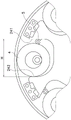
Fig. 2 is a front view of the torque fluctuation suppressing apparatus 10, and fig. 3 is a sectional view taken along line III-III of fig. 2. Note that in fig. 2, the first plate 3a is removed.
As shown in fig. 2 and 3, the torque fluctuation suppression device 10 includes a hub flange 2 (an example of a first rotating body), an inertia ring 3 (an example of a second rotating body), a centrifugal piece 4, a first rolling member 5, a cam mechanism 6, a sliding member 15, and a pair of spacers 16.
< hub Flange 2>
The hub flange 2 is configured to be rotatable. The hub flange 2 is disposed axially opposite the input-side rotating body 131. The hub flange 2 can rotate relative to the input-side rotating body 131. The hub flange 2 is joined to the output hub 14. That is, the hub flange 2 rotates integrally with the output hub 14. It should be noted that the hub flange 2 may also be constructed as one piece with the output hub 14.
The hub flange 2 is an annular plate. The hub flange 2 is thicker than a first plate 3a and a second plate 3b described later. The hub flange 2 has an inner circumferential portion 21, an outer circumferential portion 22, and a coupling portion 23. The inner peripheral portion 21 has a plurality of mounting holes 211. The inner peripheral portion 21 of the hub flange 2 is attached to the output hub 14 through the attachment hole 211. Note that the inner peripheral portion 21 is disposed outside the storage space described later.
The outer peripheral portion 22 has a plurality of receiving portions 24. In the present embodiment, the outer peripheral portion 22 has six accommodation portions 24. The plurality of receiving portions 24 are arranged at intervals in the circumferential direction. Each of the accommodating portions 24 is open toward the radially outer side. The accommodating portion 24 has a predetermined depth.
As shown in fig. 3, the outer peripheral portion 22 is accommodated in an accommodation space described later. The axial position of the outer peripheral portion 22 is different from the axial position of the inner peripheral portion 21. Specifically, the outer peripheral portion 22 is disposed on a first side in the axial direction (left side in fig. 3) with respect to the inner peripheral portion 21.
The coupling portion 23 couples the outer peripheral portion 22 and the inner peripheral portion 21. Specifically, the coupling portion 23 couples the outer peripheral end of the inner peripheral portion 21 and the inner peripheral end of the outer peripheral portion 22. The coupling portion 23 extends in the axial direction. The coupling portion 23 is cylindrical.
The hub flange 2 has a first bearing surface 25. Specifically, the coupling portion 23 has a first support surface 25. The inner peripheral surface of the coupling portion 23 constitutes a first support surface 25. The first bearing surface 25 faces radially inward. The first bearing surface 25 is annular. The first bearing surface 25 is circular in shape when viewed axially.
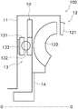
Fig. 4 is an enlarged view of the torque fluctuation suppression device 10. As shown in fig. 4, the accommodating portion 24 has a first guide surface 241, a second guide surface 242, and a bottom surface 243. The first guide surface 241, the second guide surface 242, and the bottom surface 243 constitute an inner wall surface of the accommodating portion 24.
The first guide surface 241 and the second guide surface 242 face the circumferential direction (the left-right direction in fig. 4). The first guide surface 241 and the second guide surface 242 face the centrifugal member 4. When the centrifugal member 4 is not present, the first guide surface 241 and the second guide surface 242 face each other. The first guide surface 241 and the second guide surface 242 extend substantially parallel to each other. The first and second guide surfaces 241 and 242 are flat surfaces.
The bottom surface 243 connects the first guide surface 241 and the second guide surface 242. The bottom surface 243 has a substantially circular arc shape in front view (in axial view). The bottom surface 243 faces radially outward. The bottom surface 243 faces the outer peripheral surface of the centrifugal piece 4.
< inertia Ring 3>
As shown in fig. 3 and 5, the inertia ring 3 is formed in a continuous annular shape. The inertia ring 3 functions as a mass body of the torque fluctuation suppression device 10. The inertia ring 3 is rotatable together with the hub flange 2 and is rotatable relative to the hub flange 2. The inertia ring 3 is arranged at a spacing in the axial direction with respect to the hub flange 2.
The inertia ring 3 has a first plate 3a and a second plate 3 b. The first plate 3a and the second plate 3b are arranged to sandwich the outer peripheral portion 22 of the hub flange 2 in the axial direction.
The first plate 3a and the second plate 3b are arranged with a predetermined gap in the axial direction with respect to the outer peripheral portion 22 of the hub flange 2. The axis of rotation of the inertia ring 3 is the same as the axis of rotation of the hub flange 2.
The first plate 3a and the second plate 3b are fixed by a plurality of rivets 35. Therefore, the first plate 3a and the second plate 3b cannot move in the axial direction, the radial direction, and the circumferential direction relative to each other. That is, the first plate 3a and the second plate 3b rotate integrally with each other.
As shown in fig. 3, the first plate 3a has a first annular portion 31a and a first cylindrical portion 32 a. The first annular portion 31a is annular. The first annular portion 31a is disposed on a first side in the axial direction with respect to the hub flange 2. The first annular portion 31a is disposed at a distance from the hub flange 2 in the axial direction.
The first cylindrical portion 32a extends in the axial direction from the inner peripheral end portion of the first annular portion 31a toward the second plate 3 b. That is, the first cylindrical portion 32a extends from the inner circumferential end of the first annular portion 31a to the second side in the axial direction.
The first cylindrical portion 32a is disposed radially inward of the coupling portion 23. The first cylindrical portion 32a has a second bearing surface 33. Specifically, the outer peripheral surface of the first cylindrical portion 32a constitutes the second bearing surface 33.
The second bearing surface 33 faces radially outward. The second support surface 33 is configured to be supported by the first support surface 25. Specifically, the second support surface 33 is supported by the first support surface 25 via the slide member 15. In the present embodiment, a gap is formed between the second support surface 33 and the slide member 15. When the inertia ring 3 moves in the radial direction, the second bearing surface 33 abuts against the slide member 15. It is noted that there may be no gap between the second bearing surface 33 and the slide member 15.
The second plate 3b has a second annular portion 31b and a second cylindrical portion 32 b. The second annular portion 31b is annular. The second annular portion 31b is disposed on a second side in the axial direction with respect to the hub flange 2. The second annular portion 31b is disposed at a distance from the hub flange 2 in the axial direction.
The second annular portion 31b is arranged at a distance from the first annular portion 31a in the axial direction. The second annular portion 31b is disposed on a second side in the axial direction with respect to the first annular portion 31 a. The outer peripheral portion 22 of the hub flange 2 is disposed between the first annular portion 31a and the second annular portion 31b in the axial direction.
The second cylindrical portion 32b extends in the axial direction from the outer peripheral end portion of the second annular portion 31b toward the first plate 3 a. That is, the second cylindrical portion 32b extends from the outer peripheral end portion of the second annular portion 31b to the first side in the axial direction.
The second cylindrical portion 32b is arranged radially outward of the outer peripheral portion 22 of the hub flange 2. The inner circumferential surface of the second cylindrical portion 32b faces the outer circumferential surface of the outer circumferential portion 22 of the hub flange 2. The outer peripheral portion 22 of the hub flange 2 is disposed between the first cylindrical portion 32a and the second cylindrical portion 32b in the radial direction. Note that the outer peripheral portion 22 of the hub flange 2 is disposed between the first annular portion 31a and the second annular portion 31b in the axial direction. Thus, the first plate 3a and the second plate 3b form an accommodation space that accommodates the outer peripheral portion 22 of the hub flange 2.
A first gap G1 is formed between the outer peripheral end of the first annular portion 31a and the distal end of the second cylindrical portion 32 b. That is, the outer peripheral surface of the first annular portion 31a and the inner peripheral surface of the second cylindrical portion 32b are not in contact with each other, but are spaced apart from each other. The first gap G1 may be formed over the entire circumference or only partially. Note that the outer peripheral surface of the first annular portion 31a may abut against the inner peripheral surface of the second cylindrical portion 32b, and the first gap G1 may not be formed.
A second gap G2 is formed between the inner peripheral end portion of the second annular portion 31b and the distal end portion of the first cylindrical portion 32 a. That is, the inner circumferential surface of the second annular portion 31b is not in contact with the outer circumferential surface of the first cylindrical portion 32a, but is spaced apart therefrom. The second gap G2 is formed over the entire circumference, but may be formed only partially. The coupling portion 23 of the hub flange 2 couples the inner circumferential portion 21 and the outer circumferential portion 22 via the second gap G2.
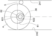
As shown in fig. 5, the first plate 3a has a plurality of second through holes 36. Specifically, the first annular portion 31a has a plurality of second through holes 36. The second through holes 36 are arranged in the circumferential direction. The second through hole 36 extends in the axial direction. The second through hole 36 axially penetrates the first annular portion 31 a. The diameter of the second through hole 36 is larger than the diameter of a small diameter portion 622 of the cam follower 62 described later. The diameter of the second through hole 36 is smaller than the small diameter portion 621 of the cam follower 62.
The first plate 3a has a plurality of restriction grooves 37. Specifically, the first annular portion 31a has a plurality of restriction grooves 37. The restriction grooves 37 are arranged in the circumferential direction. The regulating groove 37 is formed in an arc shape bulging outward in the radial direction.
The second plate 3b has a plurality of second through holes 36 and a plurality of regulating grooves 37, similarly to the first plate 3 a. The second through-holes 36 formed in the first plate 3a and the second through-holes 36 formed in the second plate 3b are formed at the same positions in the circumferential direction and the radial direction. Further, the regulating groove 37 formed in the first plate 3a and the regulating groove 37 formed in the second plate 3b are formed at the same position in the circumferential direction and the radial direction.
As shown in fig. 2, a plurality of inertia blocks 38 are disposed between the first plate 3a and the second plate 3 b. The plurality of inertia blocks 38 are arranged at intervals in the circumferential direction. For example, the inertia mass 38 and the centrifugal members 4 are alternately arranged in the circumferential direction. The inertial mass 38 is fixed to the first plate 3a and the second plate 3 b. Specifically, the inertia mass 38 is fixed to the first plate 3a and the second plate 3b by the rivet 35. It is noted that the inertia mass 38 is thicker than the eccentric 4.
< sliding Member >
As shown in fig. 2 and 3, the slide member 15 is disposed between the first support surface 25 and the second support surface 33. Specifically, the slide member 15 is attached to the first support surface 25. The slide member 15 is formed in a ring shape. The slide member 15 is press-fitted (pressed) into the coupling portion 23. Note that the plate thickness of the hub flange 2 is thicker than the first plate 3a and the second plate 3 b.
The sliding member 15 is made of a material having a lower coefficient of friction than the hub flange 2. The sliding member 15 is made of a material having a lower coefficient of friction than the inertia ring 3. For example, the sliding member 15 may be made of resin, more specifically, Polytetrafluoroethylene (PTFE), Polyetheretherketone (PEEK), Thermoplastic Polyimide (TPI), or the like.
The second support surface 33 is supported by the first support surface 25 via the slide member 15.
The center of gravity of the inertia ring 3 overlaps the first bearing surface 25 and also overlaps the second bearing surface 33 as viewed radially. Note that, when the second support surface 33 is supported by the first support surface 25 via the sliding member 15 as in the present embodiment, the center of gravity of the inertia ring 3 overlaps all of the first support surface 25, the second support surface 33, and the sliding member 15 when viewed in the radial direction.
< spacers >
A pair of spacers 16 is arranged axially between the hub flange 2 and the inertia ring 3. Specifically, one of the pads 16 is disposed between the outer peripheral portion 22 and the first plate 3a, and the other pad 16 is disposed between the outer peripheral portion 22 and the second plate 3 b.
The gasket 16 is annular. The spacer 16 may be fixed to the hub flange 2 or to the inertia ring 3. The spacer 16 is made of a material having a lower coefficient of friction than the hub flange 2 and the inertia ring 3. Specifically, the gasket 16 may be made of resin, more specifically, Polytetrafluoroethylene (PTFE), polyether ether ketone (PEEK), Thermoplastic Polyimide (TPI), or the like.
< centrifuge 4>
The centrifugal member 4 is disposed in the accommodating portion 24. The centrifugal member 4 is configured to receive a centrifugal force due to rotation of the hub flange 2. The centrifugal piece 4 is movable in the radial direction within the accommodation portion 24. Note that the centrifugal piece 4 is configured to rotate when moving in the radial direction. In the present embodiment, the centrifugal piece 4 rotates on its own axis. The axial movement of the centrifuge 4 is limited by a pair of inertia rings 3.
As shown in fig. 4, the centrifugal piece 4 has a disk shape and has a first through hole 41 in the center. That is, the centrifuge 4 is cylindrical. The centrifuge 4 is thicker than the hub flange 2. The centrifuge 4 may be formed of one piece.
The centrifugal member 4 is in contact with the second guide surface 242 and the first rolling member 5. Therefore, the movement of the centrifugal member 4 in the circumferential direction is restricted. On the other hand, the centrifugal piece 4 is movable in the radial direction. The centrifugal member 4 rolls on the second guide surface 242 of the accommodating portion 24 when moving in the radial direction. When the centrifugal piece 4 moves in the radial direction, it rolls on the first guide surface 241 via the first rolling member 5. That is, the centrifugal piece 4 rolls on the outer peripheral surface of the first rolling member 5.
Of the outer peripheral surface of the centrifugal piece 4, a surface that is in rolling contact with the outer peripheral surface of the first rolling member 5 when the centrifugal piece 4 rolls is defined as a first contact surface 42 a. Further, of the outer peripheral surface of the centrifugal piece 4, a surface that is in rolling contact with the second guide surface 242 when the centrifugal piece 4 rolls is defined as a second contact surface 42 b. The first contact surface 42a and the second contact surface 42b are arc-shaped when viewed in the axial direction.
The first through hole 41 extends in the axial direction. The first through hole 41 penetrates the centrifuge 4 in the axial direction. The diameter of the first through hole 41 is larger than the diameter of the cam follower 62. In detail, the diameter of the first through hole 41 is larger than the diameter of the large diameter portion 621 of the cam follower 62. A part of the inner wall surface defining the first through hole 41 constitutes a cam surface 61.
< first Rolling Member 5>
The first rolling member 5 is disposed between the first guide surface 241 and the centrifugal piece 4. In detail, the first rolling member 5 is sandwiched by the first guide surface 241 and the centrifugal piece 4. The first rolling member 5 is in contact with the first guide surface 241 and the centrifugal member 4.
The center of the first rolling member 5 is located radially inward of the center of the centrifugal piece 4. The first rolling member 5 is configured as a cylindrical roller. I.e. the first rolling member 5 is not a bearing.
The first rolling member 5 has a large diameter portion 51 and a pair of small diameter portions 52. The large diameter portion 51 and the small diameter portion 52 coincide with each other in center. The diameter of the large diameter portion 51 is larger than that of the small diameter portion 52. The diameter of the large-diameter portion 51 is larger than the width of the restriction groove 37. Therefore, the first rolling member 5 is axially supported by the pair of inertia rings 3.
The small diameter portions 52 project from the large diameter portion 51 to both sides in the axial direction. The diameter of the small diameter portion 52 is smaller than the width of the restriction groove 37. The small diameter portion 52 is disposed in the restriction groove 37 of the inertia ring 3. A predetermined gap is provided between the small diameter portion 52 and the inner wall surface of the regulating groove 37, and the small diameter portion 52 can smoothly move in the regulating groove 37. Since small diameter portion 52 is disposed in restriction groove 37 in this manner, the radial movement of first rolling member 5 at the time of stopping can be restricted. That is, the first rolling member 5 is supported by the regulating groove 37.
The first rolling member 5 may be constituted by one member. That is, the large diameter portion 51 and the pair of small diameter portions 52 of the first rolling member 5 are formed of one member. Note that the first rolling member 5 may be a cylindrical member having a constant diameter. The first rolling member 5 may be cylindrical.
The first rolling member 5 is configured to roll on the first guide surface 241 by the rotation of the centrifugal member 4. That is, the centrifugal member 4 rotates, and the first rolling member 5 also rotates. It is noted that the direction of rotation of the centrifugal member 4 is opposite to the direction of rotation of the first rolling member 5. The first rolling member 5 rolls on the first guide surface 241 by rotating itself. Specifically, the large diameter portion 51 of the first rolling member 5 rolls on the first guide surface 241.
In a state where there is no relative displacement in the rotational direction (rotational phase difference) between the hub flange 2 and the inertia ring 3, the small diameter portion 52 is located substantially at the center in the longitudinal direction (circumferential direction) of the regulation groove 37 as shown in fig. 5. When a rotational phase difference occurs between the hub flange 2 and the inertia ring 3, the small diameter portion 52 moves along the regulating groove 37.
As shown in fig. 6, the distance H between the first guide surface 241 and the second guide surface 242 is smaller than the sum of the diameter D1 of the centrifugal member 4 and the diameter D2 of the first rolling member 5. That is, the expression H < D1+ D2 holds. Thus, the centrifugal member 4 is always in contact with the second guide surface 242 and the first rolling member 5 during the operation of the torque fluctuation suppression device 10.
Since the diameter D2 of the first rolling member 5 is larger than the gap between the outer peripheral surface of the centrifugal piece 4 and the first guide surface 241, the first rolling member 5 is restricted from being projected outward in the radial direction.
< cam mechanism 6>
As shown in fig. 4, the cam mechanism 6 is configured to receive a centrifugal force acting on the centrifugal member 4 and convert the centrifugal force into a circumferential force in a direction in which the rotational phase difference between the hub flange 2 and the inertia ring 3 is reduced. Note that the cam mechanism 6 functions when a rotational phase difference is generated between the hub flange 2 and the inertia ring 3.
The cam mechanism 6 has a cam surface 61 and a cam follower 62. The cam surface 61 is formed in the centrifugal part 4. Specifically, the cam surface 61 is a part of the inner wall surface of the first through hole 41 of the centrifugal piece 4. The cam surface 61 is a surface against which the cam follower 62 abuts, and is arcuate when viewed in the axial direction. The cam surface 61 faces radially outward.
The cam follower 62 abuts the cam surface 61. The cam followers 62 are configured to transmit force between the centrifugal piece 4 and the pair of inertia rings 3. Specifically, the cam follower 62 extends in the first through hole 41 and the second through hole 36. The cam follower 62 is attached to the inertia ring 3 so as to be rotatable.
The cam follower 62 rolls on the cam surface 61 of the first through hole 41. Further, the cam follower 62 rolls on the inner wall surface of the second through hole 36. Note that the cam follower 62 abuts against a radially inward surface of the inner wall surface of the second through hole 36. That is, the cam follower 62 is sandwiched between the cam surface 61 and the inner wall surface of the second through hole 36.
Specifically, the cam follower 62 abuts against the cam surface 61 on the radially inner side and abuts against the inner wall surface of the second through hole 36 on the radially outer side. Thereby, the cam follower 62 is positioned. Further, since the cam follower 62 is sandwiched between the cam surface 61 and the inner wall surface of the second through hole 36 in this manner, the cam follower 62 transmits force between the centrifugal piece 4 and the pair of inertia rings 3.
The cam followers 62 are configured as cylindrical rollers. That is, the cam follower 62 is not a bearing. The cam follower 62 has a large diameter portion 621 and a pair of small diameter portions 622. The large diameter portion 621 and the small diameter portion 622 coincide with each other in center. The diameter of the large diameter portion 621 is larger than that of the small diameter portion 622. The diameter of the large diameter portion 621 is smaller than the diameter of the first through hole 41 and larger than the diameter of the second through hole 36. The large diameter portion 621 rolls on the cam surface 61.
The small diameter portions 622 protrude from the large diameter portion 621 toward both sides in the axial direction. The small diameter portion 622 rolls on the inner wall surface of the second through hole 36. The diameter of the small diameter portion 622 is smaller than the diameter of the second through hole 36. The cam follower 62 may be formed of one piece. That is, the large diameter portion 621 and the pair of small diameter portions 622 of the cam follower 62 are formed of one member. It should be noted that the cam follower 62 may also be cylindrical with a constant diameter. The cam follower 62 may be cylindrical.
When a rotational phase difference is generated between the hub flange 2 and the inertia ring 3 by contact between the cam follower 62 and the cam surface 61 and contact between the cam follower 62 and the inner wall surface of the second through hole 36, a centrifugal force generated in the centrifugal element 4 is converted into a circumferential force such that the rotational phase difference is reduced.
< stopping means >
The torque fluctuation suppression device 10 further includes a stopper mechanism 8. The stop mechanism 8 limits the relative rotational angular range of the hub flange 2 and the inertia ring 3. The stopper mechanism 8 has a convex portion 81 and a concave portion 82.
The convex portion 81 protrudes radially inward from the inertial mass 38. The recess 82 is formed in the outer peripheral surface of the hub flange 2. The convex portion 81 is disposed in the concave portion 82. The protrusion 81 abuts against the end surface of the recess 82, thereby limiting the relative rotational angle range between the hub flange 2 and the inertia ring 3.
[ operation of Torque fluctuation suppression device 10]
The operation of the torque fluctuation suppression device 10 will be described with reference to fig. 7 and 8.
When the lock is opened, the torque transmitted to the front cover 11 is transmitted to the hub flange 2 via the input side rotator 131 and the damper 132.
When there is no torque variation during torque transmission, the hub flange 2 and the inertia ring 3 rotate in a state as shown in fig. 7. In this state, the cam follower 62 of the cam mechanism 6 abuts against the radially innermost position (the circumferential central position) of the cam surface 61. In this state, the rotational phase difference between the hub flange 2 and the inertia ring 3 is "0".
As described above, the circumferential relative displacement amount between the hub flange 2 and the inertia ring 3 is referred to as a "rotational phase difference", but these represent the deviation between the circumferential center position of the centrifugal member 4 and the cam surface 61 and the center position of the second through hole 36 in fig. 7 and 8.
Here, if there is torque variation when torque is transmitted, a rotational phase difference θ is generated between the hub flange 2 and the inertia ring 3 as shown in fig. 8.
As shown in fig. 8, when the rotational phase difference θ is generated between the hub flange 2 and the inertia ring 3, the cam follower 62 of the cam mechanism 6 moves from the position shown in fig. 7 to the position shown in fig. 8. At this time, the cam follower 62 moves to the left side while rolling on the cam surface 61. Further, the cam follower 62 also rolls on the inner wall surface of the second through hole 36. Specifically, the large diameter portion 621 of the cam follower 62 rolls on the cam surface 61, and the small diameter portion 622 of the cam follower 62 rolls on the inner wall surface of the second through hole 36. Note that the cam follower 62 rotates counterclockwise.
By this movement of the cam follower 62 to the left side, the cam follower 62 presses the centrifuge 4 to the radially inner side (lower side in fig. 7 and 8) via the cam surface 61, and the centrifuge 4 moves to the radially inner side. As a result, the centrifugal part 4 moves from the position shown in fig. 7 to the position shown in fig. 8. At this time, the centrifugal member 4 rolls on the second guide surface 242. The centrifugal member 4 rotates clockwise. Note that, the centrifugal member 4 rotates clockwise, and the first rolling member 5 rotates counterclockwise. The first rolling member 5 rolls on the first guide surface 241 and moves radially inward.
In this way, since a centrifugal force acts on the centrifugal piece 4 moved to the position of fig. 8, the centrifugal piece 4 moves radially outward (upward in fig. 8). Specifically, the centrifugal member 4 rolls on the second guide surface 242 and moves radially outward. It is to be noted that the centrifugal member 4 rotates counterclockwise. In this way, the centrifugal member 4 rotates counterclockwise, and the first rolling member 5 rotates clockwise. Further, the first guide surface 241 rolls and moves radially outward.
Further, the cam surface 61 formed on the centrifugal piece 4 presses the inertia ring 3 to the right in fig. 8 via the cam follower 62, and the inertia ring 3 moves to the right in fig. 8. At this time, the large diameter portion 621 of the cam follower 62 rolls on the cam surface 61, and the small diameter portion 622 of the cam follower 62 rolls on the inner wall surface of the second through hole 36. Note that the cam follower 62 rotates clockwise. As a result, the state returns to fig. 7.
Note that when the rotational phase difference is generated in the reverse direction, the cam follower 62 moves relatively to the right in fig. 8 along the cam surface 61, but the operation principle is the same. At this time, the centrifugal piece 4 rolls on the first guide surface 241 via the first rolling member 5.
As described above, when a rotational phase difference occurs between the hub flange 2 and the inertia ring 3 due to torque variation, the hub flange 2 receives a circumferential force that reduces the rotational phase difference between the two due to the centrifugal force acting on the centrifugal member 4 and the action of the cam mechanism 6. The torque variation is suppressed by this force. It is noted that force is transmitted between the eccentric 4 and the inertia ring 3 via the cam follower 62.
The force for suppressing the above torque fluctuation changes depending on the centrifugal force, that is, the rotation speed of the hub flange 2, and also changes depending on the rotational phase difference and the shape of the cam surface 61. Therefore, by appropriately setting the shape of the cam surface 61, the characteristics of the torque fluctuation suppression device 10 can be optimized in accordance with the engine specification and the like.
Furthermore, the centrifugal member 4 moves in the radial direction by rolling indirectly or directly on the first guide surface 241 or the second guide surface 242. Therefore, the centrifugal member 4 can smoothly move in the radial direction, compared to a centrifugal member sliding on the first guide surface 241 or the second guide surface 242. The cam follower 62 rolls on the cam surface 61 and on the inner wall surface of the second through hole 36. Therefore, the force can be transmitted between the centrifugal piece 4 and the inertia ring 3 more smoothly.
[ examples of characteristics ]
Fig. 9 is a diagram showing an example of characteristics of the torque fluctuation suppression device 10. The horizontal axis represents the rotation speed, and the vertical axis represents the torque variation (rotation speed variation). A characteristic Q1 shows a case where a device for suppressing torque variation is not provided, a characteristic Q2 shows a case where an existing dynamic vibration damping device without a cam mechanism is provided, and a characteristic Q3 shows a case where the torque variation suppressing device 10 of the present embodiment is provided.
As is apparent from fig. 9, in the device provided with the dynamic vibration damping device without the cam mechanism (characteristic Q2), torque variation can be suppressed only for a specific rotation speed range. On the other hand, in the present embodiment (characteristic Q3) having the cam mechanism 6, torque variation can be suppressed in all the rotation speed ranges.
[ modified examples ]
The present invention is not limited to the above-described embodiments, and various changes and modifications may be made without departing from the scope of the present invention.
< modification 1>
In the above-described embodiment, the torque fluctuation suppression device has been described as an example of the rotation device, but the rotation device may be a device other than the torque fluctuation suppression device, and may be, for example, a clutch device, a damper device, or the like.
< modification 2>
In the above embodiment, the hub flange 2 is shown as an example of the first rotating body, but the first rotating body is not limited thereto. For example, when the torque fluctuation suppressing device is attached to the torque converter as in the present embodiment, the front cover 11, the input side rotating body 131, and the like of the torque converter 100 may be used as the first rotating body.
< modification 3>
In the above embodiment, the torque fluctuation suppression device 10 is attached to the torque converter 100, but the torque fluctuation suppression device 10 may be attached to another power transmission device such as a clutch device.
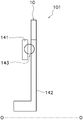
For example, as shown in fig. 10, the torque fluctuation suppression device 10 may be attached to the vibration damping device 101. The vibration damping device 101 is mounted on, for example, a hybrid vehicle. The damper device 101 includes an input member 141, an output member 142, a damper 143, and the torque fluctuation suppression device 10. Torque from the drive source is input to the input member 141. The damper 143 is disposed between the input member 141 and the output member 142. Torque from the input member 141 is transmitted to the output member 142 via the damper 143. The torque fluctuation suppression device 10 is attached to the output member 142, for example.
< modification 4>
Fig. 11 is an enlarged front view of the torque fluctuation suppression device 10 with one inertia ring 3, the centrifugal member 4, and the first rolling member 5 removed. As shown in fig. 11, the accommodating portion 24 includes a first guide surface 241, a second guide surface 242, a bottom surface 243, and a coupling surface 244.
The connecting surface 244 connects the first guide surface 241 and the bottom surface 243. The coupling surface 244 faces in the circumferential direction and in the radial direction. The connecting surface 244 is a curved surface. Specifically, the coupling surface 244 is a concave curved surface. The coupling surface 244 has an arc shape when viewed in the axial direction. The radius of curvature of the connecting surface 244 is preferably equal to or larger than the radius of the first rolling element 5. Note that, as shown in fig. 12, the connecting surface 244 may be a flat surface.
Since the connecting surface 244 is located radially inward of the first rolling member 5, it is possible to suppress the occurrence of a falling sound when the first rolling member 5 falls radially inward due to its own weight. Note that, in the present modification, the restriction groove 37 is not formed in the inertia ring 3.
< modification 5>
In the above embodiment, the first through hole 41 of the centrifugal piece 4 is a perfect circle when viewed in the axial direction, but the shape of the first through hole 41 is not limited thereto. For example, as shown in fig. 13, the first through hole 41 of the centrifugal piece 4 may not be a perfect circle when viewed in the axial direction. The following is a detailed description.
As shown in fig. 13, the inner wall surface of the first through hole 41 constitutes a cam surface 61. The cam surface 61 faces radially outward. When the torque fluctuation suppression device 10 operates, the centrifugal piece 4 moves radially outward, and the cam surface 61 abuts against the cam follower 62. Specifically, the cam surface 61 abuts against the large diameter portion 621 of the cam follower 62.
The cam surface 61 has a first region 611 and a second region 612. The first region 611 is a region in which the centrifugal piece 4 abuts against the cam follower 62 when rolling on the first guide surface 241 via the first rolling member 5. For example, when the inertia ring 3 is relatively rotated clockwise with respect to the hub flange 2, the first region 611 abuts the cam follower 62. That is, the first region 611 is a region from the radially innermost portion of the cam surface 61 to the first guide surface 241 side (the right side in fig. 13).
The second region 612 is a region where the cam follower 62 abuts when the centrifugal piece 4 rolls on the second guide surface 242. For example, when the inertia ring 3 is relatively rotated counterclockwise with respect to the hub flange 2, the second region 612 abuts the cam follower 62. That is, the second region 612 is a region from the radially innermost portion of the cam surface 61 to the second guide surface 242 side (left side in fig. 13).
The first region 611 has a curved surface shape different from that of the second region 612. The first and second regions 611 and 612 have circular arc shapes when viewed in the axial direction. In the present modification, the first region 611 has a radius of curvature smaller than that of the second region 612.
In the present modification, the right half of the first through-hole 41 is semicircular and the left half of the first through-hole 41 is also semicircular when viewed in the axial direction. The semicircle constituting the right half of the first through-hole 41 has a radius smaller than that of the semicircle constituting the left half of the first through-hole 41 as viewed in the axial direction. That is, the first through hole 41 is formed by two semicircles having different radii as viewed in the axial direction.
The boundary of the first region 611 and the second region 612 is a portion located at the radially innermost side. When the hub flange 2 and the inertia ring 3 rotate integrally without rotating relative to each other, that is, when the rotational phase difference θ between the hub flange 2 and the inertia ring 3 is zero, the boundary between the first region 611 and the second region 612 abuts on the cam follower 62.
The state of the centrifugal element 4 in which the boundary between the first region 611 and the second region 612 abuts the cam follower 62 is referred to as a neutral state. That is, when the centrifugal piece 4 is in the neutral state, the boundary between the first region 611 and the second region 612 abuts on the cam follower 62.
Fig. 14 is a front view of the torque fluctuation suppression device with the centrifugal member 4, the first rolling member 5, and the cam follower 62 removed. As shown in fig. 14, the second through hole 36 may have a non-perfect circle shape when viewed in the axial direction.
The inner wall surface of the second through hole 36 constitutes the contact surface 30. The abutment surface 30 faces radially inward. The abutment surface 30 abuts the cam follower 62. Note that, during the operation and the stop of the torque fluctuation suppression device 10, the contact surface 30 contacts the cam follower 62. Specifically, the abutment surface 30 abuts against the small diameter portion 622 of the cam follower 62.
The contact surface 30 has a third region 301 and a fourth region 302. The third region 301 is a region in which the centrifugal piece 4 abuts against the cam follower 62 when rolling on the first guide surface 241 via the first rolling member 5. For example, when the inertia ring 3 relatively rotates clockwise with respect to the hub flange 2, the third region 301 abuts the cam follower 62. That is, the third region 301 is a region from the radially outermost portion of the abutment surface 30 to the second guide surface 242 side (left side in fig. 14).
The fourth region 302 is a region in which the cam follower 62 abuts when the centrifugal piece 4 rolls on the second guide surface 242. For example, when the inertia ring 3 relatively rotates counterclockwise with respect to the hub flange 2, the fourth region 302 abuts the cam follower 62. That is, the fourth region 302 is a region from the radially outermost portion of the abutment surface 30 to the first guide surface 241 side (the right side in fig. 14).
The third region 301 has a curved surface shape different from that of the fourth region 302. The third region 301 and the fourth region 302 are arc-shaped when viewed in the axial direction. In the present modification, the third region 301 has a radius of curvature larger than that of the fourth region 302.
Note that, in the present modification, the right half of the second through hole 36 is semicircular and the left half of the second through hole 36 is also semicircular when viewed in the axial direction. The semicircle constituting the right half of the second through hole 36 has a radius smaller than that of the semicircle constituting the left half of the second through hole 36 as viewed in the axial direction. That is, the second through hole 36 is formed by two semicircles having different radii as viewed in the axial direction.
The boundary between the third region 301 and the fourth region 302 is a radially outermost portion. When the centrifuge 4 is in the neutral state, the cam follower 62 abuts on the boundary between the third region 301 and the fourth region 302.
As shown in fig. 13, the torque fluctuation suppression device 10 includes a state maintaining mechanism 7. The state maintaining mechanism 7 is configured to maintain the neutral state of the centrifugal member 4 when the hub flange 2 and the inertia ring 3 rotate integrally, that is, when the rotational phase difference θ is zero. Therefore, when the rotational phase difference θ is zero, the boundary of the first region 611 and the second region 612 contacts the cam follower 62.
The state maintaining mechanism 7 includes a first engaging portion 71 and an engaging portion 72. The first engaging portion 71 is formed in the hub flange 2. The first engaging portion 71 projects from the hub flange 2 toward the centrifugal piece 4.
The second engaging portion 72 is formed in the centrifugal piece 4. The second engaging portion 72 is a recess formed in the centrifugal piece 4. The second engaging portion 72 engages with the first engaging portion 71. Specifically, the first engaging portion 71 is disposed in the second engaging portion 72. Therefore, the first engagement portion 71 and the second engagement portion 72 abut against each other, and as a result, the rotation of the centrifuge 4 is restricted when the hub flange 2 and the inertia ring 3 do not rotate relative to each other.
Next, the operation of the torque fluctuation suppression device 10 will be described. First, as shown in fig. 15, when the hub flange 2 and the inertia ring 3 do not rotate relative to each other, that is, when the rotational phase difference θ is zero, the centrifugal piece 4 is in the neutral state. Therefore, the cam follower 62 abuts the boundary of the first region 611 and the second region 612. Further, the cam follower 62 abuts on the boundary between the third region 301 and the fourth region 302. The centrifuge 4 does not spin.
As shown in fig. 16, when the inertia ring 3 relatively rotates counterclockwise with respect to the hub flange 2, the centrifugal member 4 rolls on the second guide surface 242. It is noted that the centrifugal element 4 rolls clockwise.
The cam follower 62 rolls over a second region 612 in the cam surface 61. Further, the cam follower 62 rolls on the fourth region 302 in the abutment surface 30. As such, the cam follower 62 is sandwiched between the second region 612 and the fourth region 302. Note that the cam follower 62 rolls counterclockwise.
As shown in fig. 17, when the inertia ring 3 rotates clockwise relative to the hub flange 2, the centrifugal piece 4 rolls on the first guide surface 241 via the first rolling member 5. It is noted that the centrifugal element 4 rolls clockwise.
The cam follower 62 rolls on the first region 611 in the cam surface 61. Further, the cam follower 62 rolls on the third region 301 in the abutment surface 30. In this way, the cam follower 62 is sandwiched between the first region 611 and the third region 301. Note that the cam follower 62 rolls clockwise.
Here, the centrifugal member 4 rolls on the first guide surface 241 through the first rolling member 5, not directly on the first guide surface 241. Therefore, if the radius of curvature of the first region 611 is made the same as the radius of curvature of the second region 612, there is a possibility that the angle formed by the first tangent and the second tangent deviates from an appropriate range. As a result, there is a possibility that the cam follower 62 cannot be firmly clamped by the abutment surface 30 and the cam surface 61. Note that the first tangent line means a tangent line at a contact point of the cam follower 62 with the cam surface 61, and the second tangent line means a tangent line at a contact point of the cam follower 62 with the abutment surface 30.
In contrast, in the present modification, since the first region 611 has a different radius of curvature from the second region 612, specifically, since the radius of curvature of the first region 611 is made smaller than the radius of curvature of the second region 612, the angle formed by the first tangent line and the second tangent line can be made within an appropriate range, and the cam follower 62 can be firmly sandwiched by the cam surface 61 and the abutment surface 30.
In the present modification, since the third region 301 has a radius of curvature different from that of the fourth region 302, specifically, since the radius of curvature of the third region 301 is made larger than that of the fourth region 302, the angle formed by the first tangent line and the second tangent line can be made within an appropriate range, and the cam follower 62 can be firmly sandwiched by the cam surface 61 and the abutment surface 30.
Note that, as shown in fig. 18, the third region 301 and the fourth region 302 may have different curved surface shapes, and on the other hand, the first region 611 and the second region 612 may have the same curved surface shape. As shown in fig. 19, the first region 611 and the second region 612 may have different curved surface shapes, and the third region 301 and the fourth region 302 may have the same curved surface shape.
< modification 6>
In the above embodiment, the second plate 3b has the second cylindrical portion 32b, but the configuration of the inertia ring 3 is not limited thereto. For example, as shown in fig. 20, the first plate 3a may have a second cylindrical portion 32 b. In this case, the first plate 3a has a first annular portion 31a, a first cylindrical portion 32a, and a second cylindrical portion 32 b. The first cylindrical portion 32a extends in the axial direction from the inner peripheral end portion of the first annular portion 31a toward the second plate 3 b. The second cylindrical portion 32b extends in the axial direction from the outer peripheral end portion of the first annular portion 31a toward the second plate 31 b.
Note that a first gap G1 is formed between the front end portion of the second cylindrical portion 32b and the outer peripheral end portion of the second annular portion 31 b. That is, the outer peripheral surface of the second annular portion 31b is spaced apart from the inner peripheral surface of the second cylindrical portion 32b without contacting the same. The first gap G1 may be formed over the entire circumference or only partially. Note that the outer peripheral surface of the second annular portion 31b may abut against the inner peripheral surface of the second cylindrical portion 32b without forming the first gap G1.
In a modification, the second plate 3b may have only the second annular portion 31b and not the second cylindrical portion 32 b.
Claims (23)
1. A rotation device is provided with:
a first rotating body configured to be rotatable; and
a second rotating body configured to be rotatable together with the first rotating body and to be rotatable relative to the first rotating body,
the second rotating body has a first plate and a second plate,
the first plate and the second plate are configured to form an accommodation space that accommodates an outer peripheral portion of the first rotating body.
2. The rotating apparatus according to claim 1,
the first plate has:
a first annular portion; and
a first cylindrical portion extending in an axial direction from an inner peripheral end portion of the first annular portion toward the second plate,
the second plate has:
a second annular portion arranged at an interval from the first annular portion in an axial direction; and
a second cylindrical portion extending in an axial direction from an outer peripheral end portion of the second annular portion toward the first plate.
3. The rotating apparatus according to claim 2,
the first annular portion is disposed with a first gap between an outer peripheral end portion of the first annular portion and a distal end portion of the second cylindrical portion.
4. The rotating apparatus according to claim 1,
the first plate has:
a first annular portion;
a first cylindrical portion extending in an axial direction from an inner peripheral end portion of the first annular portion toward the second plate; and
a second cylindrical portion extending in an axial direction from an outer peripheral end portion of the first annular portion toward the second plate,
the second plate has a second annular portion arranged at a distance from the first annular portion in the axial direction.
5. The rotating apparatus according to any one of claims 2 to 4,
the second annular portion is disposed with a second gap between an inner peripheral end portion of the second annular portion and a distal end portion of the first cylindrical portion.
6. The rotating apparatus according to claim 5,
the first rotating body includes:
an inner peripheral portion disposed outside the accommodation space; and
and a coupling portion that couples the outer peripheral portion and the inner peripheral portion with each other through the second gap.
7. The rotating apparatus according to claim 6,
the coupling portion has a first bearing surface facing radially inward,
the first cylindrical portion has a second support surface that faces in a radial direction so as to be supported by the first support surface.
8. The rotating apparatus according to claim 7,
the rotating device further includes a sliding member disposed between the first support surface and the second support surface.
9. The rotating apparatus according to claim 8,
the first rotating body is plate-shaped thicker than the second rotating body,
the sliding member is attached to the first support surface.
10. The rotating apparatus according to any one of claims 1 to 9,
the rotating device further includes a spacer disposed between the first rotating body and the second rotating body in the axial direction.
11. The rotating apparatus according to any one of claims 1 to 10,
the rotating device is further provided with a centrifugal member configured to be radially movable,
the first rotating body has a housing portion that houses the centrifugal member.
12. The rotating apparatus according to claim 11,
the centrifugal member is configured to rotate when moving in a radial direction.
13. The rotating apparatus according to claim 12,
the rotating device is also provided with a first rolling component,
the accommodating portion has a first guide surface and a second guide surface facing the circumferential direction,
the first rolling member is disposed between the first guide surface and the centrifugal member, and is configured to roll on the first guide surface by the rotation of the centrifugal member.
14. The rotating apparatus according to claim 13,
the centrifugal member is configured to roll on the second guide surface.
15. The rotating apparatus according to claim 13 or 14,
the centrifugal member and the first rolling member are cylindrical or columnar,
the distance between the first guide surface and the second guide surface is smaller than the sum of the diameter of the centrifugal member and the diameter of the first rolling member.
16. The rotating apparatus according to any one of claims 11 to 15,
the rotating device further includes a cam mechanism that receives a centrifugal force acting on the centrifugal member and converts the centrifugal force into a circumferential force in a direction in which a rotational phase difference between the first rotating body and the second rotating body decreases.
17. The rotating apparatus according to claim 16,
the cam mechanism includes:
a cam surface formed on the centrifugal member; and
and a cam follower that abuts against the cam surface and transmits force between the centrifugal member and the second rotating body.
18. The rotating apparatus according to claim 17,
the cam follower rolls on the cam surface.
19. The rotating apparatus according to claim 17 or 18,
the centrifugal member has a first through hole penetrating in an axial direction,
the cam surface is formed by an inner wall surface of the first through hole.
20. The rotating apparatus according to any one of claims 17 to 19,
the cam follower is attached to the second rotating body so as to be rotatable.
21. The rotating apparatus according to any one of claims 17 to 20,
the second rotating body has a second through-hole,
the cam follower rolls on an inner wall surface of the second through hole.
22. The rotating apparatus according to any one of claims 17 to 21,
the cam follower is a cylindrical or cylindrical roller.
23. A power transmission device is provided with:
an input section;
an output member to which torque is transmitted from the input member; and
the rotating apparatus according to any one of claims 1 to 22.
Applications Claiming Priority (2)
| Application Number | Priority Date | Filing Date | Title |
|---|---|---|---|
| JP2021-021568 | 2021-02-15 | ||
| JP2021021568A JP2022124037A (en) | 2021-02-15 | 2021-02-15 | Rotation device and power transmission device |
Publications (1)
| Publication Number | Publication Date |
|---|---|
| CN114941689A true CN114941689A (en) | 2022-08-26 |
Family
ID=82800264
Family Applications (1)
| Application Number | Title | Priority Date | Filing Date |
|---|---|---|---|
| CN202210022810.1A Pending CN114941689A (en) | 2021-02-15 | 2022-01-10 | Rotating device and power transmission device |
Country Status (3)
| Country | Link |
|---|---|
| US (1) | US20220260143A1 (en) |
| JP (1) | JP2022124037A (en) |
| CN (1) | CN114941689A (en) |
Families Citing this family (1)
| Publication number | Priority date | Publication date | Assignee | Title |
|---|---|---|---|---|
| US11927254B2 (en) * | 2020-07-07 | 2024-03-12 | Exedy Corporation | Rotary device and power transmission device |
Family Cites Families (8)
| Publication number | Priority date | Publication date | Assignee | Title |
|---|---|---|---|---|
| US3373633A (en) * | 1965-10-23 | 1968-03-19 | Houdaille Industries Inc | Viscous torsional vibration dampers |
| US5816372A (en) * | 1994-09-09 | 1998-10-06 | Lord Corporation | Magnetorheological fluid devices and process of controlling force in exercise equipment utilizing same |
| EP2843262B1 (en) * | 2012-04-27 | 2019-11-27 | Toyota Jidosha Kabushiki Kaisha | Vibration damping device |
| JP2014206237A (en) * | 2013-04-15 | 2014-10-30 | トヨタ自動車株式会社 | Torsional vibration attenuation device |
| FR3039235B1 (en) * | 2015-07-24 | 2019-04-12 | Valeo Embrayages | VIBRATION DAMPING DEVICE |
| US11927254B2 (en) * | 2020-07-07 | 2024-03-12 | Exedy Corporation | Rotary device and power transmission device |
| JP2022124036A (en) * | 2021-02-15 | 2022-08-25 | 株式会社エクセディ | Rotation device and power transmission device |
| CN114941690A (en) * | 2021-02-15 | 2022-08-26 | 株式会社艾科赛迪 | Rotating device and power transmission device |
-
2021
- 2021-02-15 JP JP2021021568A patent/JP2022124037A/en active Pending
-
2022
- 2022-01-10 CN CN202210022810.1A patent/CN114941689A/en active Pending
- 2022-01-14 US US17/576,403 patent/US20220260143A1/en not_active Abandoned
Also Published As
| Publication number | Publication date |
|---|---|
| US20220260143A1 (en) | 2022-08-18 |
| JP2022124037A (en) | 2022-08-25 |
Similar Documents
| Publication | Publication Date | Title |
|---|---|---|
| CN107850178B (en) | Torque fluctuation suppression device, torque converter, and power transmission device | |
| JP6709765B2 (en) | Torque fluctuation suppressing device, torque converter, and power transmission device | |
| CN110300862B (en) | Torque fluctuation suppression device, torque converter, and power transmission device | |
| US20220260142A1 (en) | Rotary device and power transmission device | |
| JP6712586B2 (en) | Torque fluctuation suppressing device, torque converter, and power transmission device | |
| US20210131525A1 (en) | Torque fluctuation inhibiting device and power transmission device | |
| US10808797B2 (en) | Torque fluctuation inhibiting device, torque converter and power transmission device | |
| CN111692285B (en) | Torque ripple suppression device and torque converter | |
| CN111609089A (en) | Rotating device | |
| CN110608263A (en) | Torque fluctuation suppression device | |
| CN114941689A (en) | Rotating device and power transmission device | |
| CN111692284B (en) | Torque ripple suppression device and torque converter | |
| CN113915291A (en) | Rotating device and power transmission device | |
| JP7376291B2 (en) | Torque fluctuation suppression device and power transmission device | |
| US11761523B2 (en) | Rotary device and power transmission device | |
| CN111609108A (en) | Rotating device | |
| JP6709764B2 (en) | Torque fluctuation suppressing device, torque converter, and power transmission device | |
| US11428292B2 (en) | Torque fluctuation inhibiting device and torque converter | |
| JP6709767B2 (en) | Torque fluctuation suppressing device, torque converter, and power transmission device | |
| EP3708867A1 (en) | Damper device | |
| JP2022014863A (en) | Rotating device and power transmission device | |
| JP2022112223A (en) | Rotary device and power transmission device | |
| JP6682572B2 (en) | Torque fluctuation suppression device | |
| JP2022110934A (en) | Rotary device and power transmission device | |
| JP2022124447A (en) | Rotation device and power transmission device |
Legal Events
| Date | Code | Title | Description |
|---|---|---|---|
| PB01 | Publication | ||
| PB01 | Publication |