CN110300862B - Torque fluctuation suppression device, torque converter, and power transmission device - Google Patents
Torque fluctuation suppression device, torque converter, and power transmission device Download PDFInfo
- Publication number
- CN110300862B CN110300862B CN201880012220.2A CN201880012220A CN110300862B CN 110300862 B CN110300862 B CN 110300862B CN 201880012220 A CN201880012220 A CN 201880012220A CN 110300862 B CN110300862 B CN 110300862B
- Authority
- CN
- China
- Prior art keywords
- centrifugal
- rotating body
- torque
- cam
- inertia ring
- Prior art date
- Legal status (The legal status is an assumption and is not a legal conclusion. Google has not performed a legal analysis and makes no representation as to the accuracy of the status listed.)
- Active
Links
Images


Classifications
-
- F—MECHANICAL ENGINEERING; LIGHTING; HEATING; WEAPONS; BLASTING
- F16—ENGINEERING ELEMENTS AND UNITS; GENERAL MEASURES FOR PRODUCING AND MAINTAINING EFFECTIVE FUNCTIONING OF MACHINES OR INSTALLATIONS; THERMAL INSULATION IN GENERAL
- F16H—GEARING
- F16H45/00—Combinations of fluid gearings for conveying rotary motion with couplings or clutches
- F16H45/02—Combinations of fluid gearings for conveying rotary motion with couplings or clutches with mechanical clutches for bridging a fluid gearing of the hydrokinetic type
-
- F—MECHANICAL ENGINEERING; LIGHTING; HEATING; WEAPONS; BLASTING
- F16—ENGINEERING ELEMENTS AND UNITS; GENERAL MEASURES FOR PRODUCING AND MAINTAINING EFFECTIVE FUNCTIONING OF MACHINES OR INSTALLATIONS; THERMAL INSULATION IN GENERAL
- F16F—SPRINGS; SHOCK-ABSORBERS; MEANS FOR DAMPING VIBRATION
- F16F15/00—Suppression of vibrations in systems; Means or arrangements for avoiding or reducing out-of-balance forces, e.g. due to motion
- F16F15/10—Suppression of vibrations in rotating systems by making use of members moving with the system
- F16F15/12—Suppression of vibrations in rotating systems by making use of members moving with the system using elastic members or friction-damping members, e.g. between a rotating shaft and a gyratory mass mounted thereon
- F16F15/131—Suppression of vibrations in rotating systems by making use of members moving with the system using elastic members or friction-damping members, e.g. between a rotating shaft and a gyratory mass mounted thereon the rotating system comprising two or more gyratory masses
- F16F15/133—Suppression of vibrations in rotating systems by making use of members moving with the system using elastic members or friction-damping members, e.g. between a rotating shaft and a gyratory mass mounted thereon the rotating system comprising two or more gyratory masses using springs as elastic members, e.g. metallic springs
- F16F15/134—Wound springs
-
- F—MECHANICAL ENGINEERING; LIGHTING; HEATING; WEAPONS; BLASTING
- F16—ENGINEERING ELEMENTS AND UNITS; GENERAL MEASURES FOR PRODUCING AND MAINTAINING EFFECTIVE FUNCTIONING OF MACHINES OR INSTALLATIONS; THERMAL INSULATION IN GENERAL
- F16F—SPRINGS; SHOCK-ABSORBERS; MEANS FOR DAMPING VIBRATION
- F16F15/00—Suppression of vibrations in systems; Means or arrangements for avoiding or reducing out-of-balance forces, e.g. due to motion
- F16F15/10—Suppression of vibrations in rotating systems by making use of members moving with the system
- F16F15/14—Suppression of vibrations in rotating systems by making use of members moving with the system using masses freely rotating with the system, i.e. uninvolved in transmitting driveline torque, e.g. rotative dynamic dampers
- F16F15/1407—Suppression of vibrations in rotating systems by making use of members moving with the system using masses freely rotating with the system, i.e. uninvolved in transmitting driveline torque, e.g. rotative dynamic dampers the rotation being limited with respect to the driving means
- F16F15/145—Masses mounted with play with respect to driving means thus enabling free movement over a limited range
- F16F15/1457—Systems with a single mass
-
- F—MECHANICAL ENGINEERING; LIGHTING; HEATING; WEAPONS; BLASTING
- F16—ENGINEERING ELEMENTS AND UNITS; GENERAL MEASURES FOR PRODUCING AND MAINTAINING EFFECTIVE FUNCTIONING OF MACHINES OR INSTALLATIONS; THERMAL INSULATION IN GENERAL
- F16H—GEARING
- F16H25/00—Gearings comprising primarily only cams, cam-followers and screw-and-nut mechanisms
- F16H25/18—Gearings comprising primarily only cams, cam-followers and screw-and-nut mechanisms for conveying or interconverting oscillating or reciprocating motions
-
- F—MECHANICAL ENGINEERING; LIGHTING; HEATING; WEAPONS; BLASTING
- F16—ENGINEERING ELEMENTS AND UNITS; GENERAL MEASURES FOR PRODUCING AND MAINTAINING EFFECTIVE FUNCTIONING OF MACHINES OR INSTALLATIONS; THERMAL INSULATION IN GENERAL
- F16H—GEARING
- F16H45/00—Combinations of fluid gearings for conveying rotary motion with couplings or clutches
- F16H45/02—Combinations of fluid gearings for conveying rotary motion with couplings or clutches with mechanical clutches for bridging a fluid gearing of the hydrokinetic type
- F16H2045/0221—Combinations of fluid gearings for conveying rotary motion with couplings or clutches with mechanical clutches for bridging a fluid gearing of the hydrokinetic type with damping means
- F16H2045/0263—Combinations of fluid gearings for conveying rotary motion with couplings or clutches with mechanical clutches for bridging a fluid gearing of the hydrokinetic type with damping means the damper comprising a pendulum
Abstract
The invention relates to a torque fluctuation suppression device, a torque converter, and a power transmission device, which suppress a peak value of torque fluctuation in a relatively wide rotation speed region. The device is provided with an inertia ring (20), a plurality of centrifugal members (21), a plurality of cam mechanisms (22), and a plurality of restricting mechanisms (23). The inertia ring (20) is rotatable together with the hub rim (12), and is arranged to be rotatable relative to the hub rim (12). The centrifugal piece (21) is configured to be subjected to a centrifugal force generated by rotation of the hub rim (12) and the inertia ring (20). The cam mechanism (22) receives a centrifugal force acting on the centrifugal piece (21), and when relative displacement in the rotational direction is generated between the hub rim (12) and the inertia ring (20), converts the centrifugal force into a circumferential force in a direction in which the relative displacement is reduced. The restricting mechanism (23) allows the centrifugal member (21) to be actuated by the cam mechanism and restricts the radial movement of the centrifugal member.
Description
Technical Field
The present invention relates to a torque fluctuation suppression device, and more particularly to a torque fluctuation suppression device for suppressing torque fluctuation of a rotating body that rotates around a rotation axis and to which torque is input. The present invention also relates to a torque converter and a power transmission device provided with the torque fluctuation suppression device.
Background
For example, a clutch device including a damper device and a torque converter are provided between an engine and a transmission of an automobile. Further, the torque converter is provided with a lock-up device for mechanically transmitting torque at a rotational speed equal to or higher than a predetermined rotational speed, so as to reduce fuel consumption.
The locking device generally has a clutch portion and a damper having a plurality of torsion springs. The clutch unit has a piston with a friction member that is pressed against the front cover by a hydraulic pressure. In the unlocked state, torque is transmitted from the front cover to the piston via the friction member, and further to the output-side member via the torsion springs.
In such a lock device, torque variation (rotational speed variation) is suppressed by a damper having a plurality of torsion springs.
In the lock device of patent document 1, torque variation is suppressed by providing a dynamic damper device including an inertia member. The dynamic damper device of patent document 1 is attached to a plate supporting a torsion spring, and includes a pair of inertia rings rotatable relative to the plate, and a plurality of coil springs provided between the plate and the inertia rings.
Documents of the prior art
Patent document
Patent document 1: japanese patent laid-open publication No. 2015-094424
Disclosure of Invention
In the conventional dynamic damper device including patent document 1, a peak of torque variation occurring in a predetermined rotation speed region can be suppressed. However, when the engine specification or the like changes, the rotation speed region in which the peak of the torque fluctuation occurs changes accordingly. Therefore, the inertia amount of the inertia ring and the spring constant of the coil spring need to be changed in accordance with a change in the specification of the engine or the like, and it is sometimes difficult to cope with these changes.
The present invention addresses the problem of suppressing the peak of torque variation in a relatively wide rotational speed range in a device for suppressing torque variation in a rotating member.
(1) The torque fluctuation suppression device according to the present invention is a device that suppresses torque fluctuation of a rotating body to which torque is input. The torque fluctuation suppression device includes a mass body, a plurality of centrifugal members, a plurality of cam mechanisms, and a plurality of restriction mechanisms. The mass body is rotatable together with the rotating body and is arranged to be rotatable relative to the rotating body. The plurality of centrifugal members are configured to receive a centrifugal force generated by rotation of the rotating body and the mass body. When a relative displacement in the rotational direction is generated between the rotating body and the mass body upon receiving a centrifugal force acting on the centrifugal member, the plurality of cam mechanisms convert the centrifugal force into a circumferential force in a direction in which the relative displacement is reduced. A plurality of limiting mechanisms allow the centrifugal member to act through the cam mechanism and limit the radial movement of the centrifugal member.
In this device, when a torque is input to the rotating body, the rotating body and the mass body rotate. When the torque input to the rotating body is not varied, the rotating body and the mass body rotate synchronously without generating relative displacement in the rotating direction. On the other hand, when the input torque fluctuates, since the mass body is arranged to be rotatable with respect to the rotating body, a relative displacement in the rotational direction (hereinafter, this displacement may be expressed as "rotational phase difference") occurs between the two depending on the degree of the fluctuation of the torque.
Here, when the rotating body and the mass body rotate, the centrifugal element receives a centrifugal force. When relative displacement occurs between the rotating body and the mass body, the cam mechanism converts a centrifugal force acting on the centrifugal element into a circumferential force that acts to reduce the relative displacement between the rotating body and the mass body. By the operation of the cam mechanism, torque variation is suppressed.
Here, the centrifugal force acting on the centrifugal member is used as a force for suppressing torque variation, and thus the characteristic for suppressing torque variation changes depending on the rotation speed of the rotating body. Further, the characteristic of suppressing the torque variation can be appropriately set according to, for example, the shape of the cam, and the peak value of the torque variation in a wider rotation speed region can be suppressed.
Here, the movement of the centrifugal element in the radial direction is restricted by the restricting mechanism while allowing the centrifugal element to be operated by the cam mechanism. Therefore, it is possible to avoid the centrifugal piece from moving in the radial direction and colliding with another member such as the rotary body to generate collision noise. Further, even when the centrifugal piece collides with another member, the collision noise at the time of collision can be suppressed.
(2) Preferably, the restricting mechanism has a restricting shaft and a restricting groove. The regulating shaft is provided on one of the mass body and the centrifugal member, and extends along the rotation axis of the rotating body. The regulating groove is formed in the other of the mass body and the centrifugal member, and the regulating shaft is inserted into the regulating groove.
Here, for example, the centrifugal piece is provided with a restricting shaft which is inserted into a restricting groove formed in the mass body, for example. Therefore, when the centrifugal member is operated, the regulating shaft is regulated by the regulating groove, and the radial movement of the centrifugal member is finally regulated.
Therefore, the restricting mechanism can be realized with a simple configuration. In addition, since the regulating shaft is inserted into the regulating groove, the centrifugal piece can be regulated from moving to the outside and the inside in the radial direction.
(3) Preferably, the further limiting means each have a further limiting shaft and a limiting surface. The regulating shaft is provided to the mass body and extends along the rotation axis of the rotating body. The regulating surface is formed on the inner peripheral surface of the centrifugal piece, and the regulating shaft slides on the regulating surface.
Here, the centrifugal member operates while a regulating surface formed on the inner peripheral surface abuts against a regulating shaft provided on the mass body. Therefore, the movement of the centrifugal member radially inward can be restricted. Further, it is not necessary to form a groove for guiding the restricting shaft, and the configuration becomes simpler.
(4) Preferably, the stopper further includes an elastic body provided on an outer peripheral surface of the stopper shaft or a surface against which the stopper shaft abuts.
In this case, the collision between the restricting shaft and the portion that collides with the restricting shaft can be alleviated, and the collision sound at the time of collision can be further suppressed.
(5) Preferably, the rotating body has a plurality of recesses on an outer peripheral surface thereof, and the plurality of centrifugal pieces are respectively accommodated in the recesses of the rotating body. The restricting mechanism restricts the inner peripheral surface of the centrifugal member from abutting the bottom surface of the recess.
Here, when the rotating body and the mass body rotate, the centrifugal element attempts to move radially outward by receiving a centrifugal force. On the other hand, when the rotation of the rotating body and the mass body is stopped, the centrifugal force is not applied to the centrifugal member. Therefore, when the regulating mechanism is not provided, the centrifugal piece positioned above the plurality of centrifugal pieces falls downward and collides with the bottom surface of the recess. When the collision occurs, a collision sound is generated.
However, here, the radial movement of the centrifugal member is restricted by the restricting mechanism, thereby preventing the centrifugal member from colliding with the bottom surface of the recess. Therefore, the collision sound of the centrifugal piece with the bottom surface of the recess can be eliminated when the rotation is stopped.
(6) Preferably, the cam mechanism includes a cam provided on one of the mass body and the centrifugal member and a cam follower provided on the other of the mass body and the centrifugal member and moving along the cam.
Here, the relative displacement amount in the rotational direction between the rotating body and the mass body varies according to the magnitude of the torque variation of the rotating body. In this case, the cam is shaped such that the circumferential force converted from the centrifugal force changes in accordance with the relative displacement amount, whereby torque fluctuation can be more effectively suppressed.
(7) Preferably, the mass body includes a first inertia ring and a second inertia ring disposed to face each other with the rotating body interposed therebetween, and a pin connecting the first inertia ring and the second inertia ring to be incapable of relative rotation. The centrifugal member is disposed between the first inertia ring and the second inertia ring in the axial direction at the outer peripheral portion of the rotating body and on the inner peripheral side of the pin. The cam follower is a cylindrical roller having a hole through which the pin passes in the axial direction. The cam is formed on the centrifugal member, abuts against the cam follower, and has a shape in which a circumferential force changes in accordance with a relative displacement amount in a rotational direction between the rotating body and the mass body.
Here, the cam follower is mounted using a pin connecting the first inertia ring and the second inertia ring. Therefore, the configuration of the cam mechanism becomes simple.
(8) The torque converter according to the present invention is disposed between an engine and a transmission. The torque converter is provided with: the torque converter includes an input-side rotating body to which torque is input from an engine, an output-side rotating body to which torque is output to a transmission, a damper disposed between the input-side rotating body and the output-side rotating body, and any one of the above-described torque fluctuation suppression devices.
(9) The power transmission device according to the present invention includes a flywheel, a clutch device, and any one of the torque fluctuation suppression devices described above. The flywheel includes a first inertial body that rotates about a rotation axis, a second inertial body that rotates about the rotation axis and freely rotates relative to the first inertial body, and a damper disposed between the first inertial body and the second inertial body. The clutch device is arranged on the second inertia body of the flywheel.
In the present invention as described above, in the device for suppressing torque variation of the rotating member, the peak of torque variation can be suppressed in a relatively wide rotation speed range. In addition, in the present invention, collision noise can be suppressed in which the centrifugal piece collides with another member.
Drawings
Fig. 1 is a schematic diagram of a torque converter according to a first embodiment of the present invention.
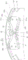
Fig. 2 is a partial front view of the hub rim and the torque fluctuation suppression device of fig. 1.
Fig. 3 is a view from direction a of fig. 2.
Fig. 4 is an external perspective view of the portion shown in fig. 2.
Fig. 5 is a diagram for explaining the operation of the cam mechanism.
Fig. 6 is a diagram for explaining the operation of the cam mechanism.
Fig. 7 is a characteristic diagram showing a relationship between the rotation speed and the torque variation.
Fig. 8 is a diagram corresponding to fig. 2 of a second embodiment of the present invention.
Fig. 9 is a diagram for explaining the operation of the cam mechanism according to the second embodiment.
Fig. 10 is a diagram for explaining the operation of the cam mechanism according to the second embodiment.
Fig. 11 is a view corresponding to fig. 2 of a third embodiment of the present invention.
Fig. 12 is a view corresponding to fig. 2 of a fourth embodiment of the present invention.
Fig. 13 is a diagram corresponding to fig. 2 of a fifth embodiment of the present invention.
Fig. 14 is a schematic diagram showing application example 1 of the present invention.
Fig. 15 is a schematic diagram showing application example 2 of the present invention.
Fig. 16 is a schematic diagram showing application example 3 of the present invention.
Fig. 17 is a schematic diagram showing application example 4 of the present invention.
Fig. 18 is a schematic diagram showing application example 5 of the present invention.
Fig. 19 is a schematic diagram showing application example 6 of the present invention.
Fig. 20 is a schematic diagram showing application example 7 of the present invention.
Fig. 21 is a schematic diagram showing application example 8 of the present invention.
Fig. 22 is a schematic diagram showing application example 9 of the present invention.
Detailed Description
First embodiment
Fig. 1 is a schematic diagram of a torque fluctuation suppression device according to a first embodiment of the present invention when mounted to a lock-up device of a torque converter. In FIG. 1, O-O is the rotational axis of the torque converter.
[ integral constitution ]
The torque converter 1 has a front cover 2, a torque converter main body 3, a lock device 4, and an output hub 5. The front cover 2 receives torque from the engine. The torque converter main body 3 includes an impeller 7 connected to the front cover 2, a turbine 8, and a stator (not shown). The turbine 8 is connected to the output hub 5, and an input shaft (not shown) of the transmission is spline-engaged with an inner peripheral portion of the output hub 5.
[ locking device 4]
The lock device 4 includes a clutch portion, a piston that is operated by hydraulic pressure, and the like, and can adopt a lock-on state and a lock-off state. In the lock-on state, torque input to the front cover 2 is transmitted to the output hub 5 via the lock-up device 4, not via the torque converter main body 3. On the other hand, in the lock-up closed state, the torque input to the front cover 2 is transmitted to the output hub 5 via the torque converter body 3.
The lock device 4 includes an input-side rotating body 11, a hub flange 12 (rotating body), a damper 13, and a torque fluctuation suppression device 14.
The input-side rotating body 11 includes a piston that is movable in the axial direction, and a friction member 16 is fixed to a side surface on the front cover 2 side. The friction member 16 is pressed against the front cover 2, and torque is transmitted from the front cover 2 to the input-side rotating body 11.
The hub flange 12 is disposed axially opposite to the input-side rotating body 11, and is rotatable relative to the input-side rotating body 11. The hub rim 12 is connected to the output hub 5.
The damper 13 is disposed between the input-side rotating body 11 and the hub rim 12. The damper 13 has a plurality of torsion springs elastically connecting the input side rotary body 11 and the hub rim 12 in the rotational direction. The damper 13 absorbs and attenuates torque fluctuations while transmitting torque from the input-side rotating body 11 to the hub rim 12.
[ Torque fluctuation suppression device 14]
Fig. 2 is a front view of the hub rim 12 and the torque fluctuation suppression device 14. Fig. 2 is a view showing one side (front side) of the inertia ring removed. Fig. 3 is a view seen from a direction a of fig. 2, and fig. 4 is an external perspective view of fig. 2. Fig. 2 and the following drawings show a part of the hub flange 12 and the torque fluctuation suppression device 14, but the parts shown in the respective drawings are provided at four positions in the circumferential direction at equal angular intervals as a whole.
The torque fluctuation suppression device 14 includes a first inertia ring 201 and a second inertia ring 202 that constitute the mass body 20, four centrifugal members 21, four cam mechanisms 22, and four limiting mechanisms 23.
< first inertia ring 201 and second inertia ring 202 >
The first inertia ring 201 and the second inertia ring 202 are each a plate formed in a continuous annular shape and having a predetermined thickness, and are disposed at predetermined gaps on both sides of the hub rim 12 in the axial direction with the hub rim 12 therebetween, as shown in fig. 3. That is, the hub flange 12, the first inertia ring 201, and the second inertia ring 202 are arranged in an axial direction. The first inertia ring 201 and the second inertia ring 202 have the same rotation axis as the rotation axis of the hub rim 12, are rotatable together with the hub rim 12, and are rotatable with respect to the hub rim 12.
< hub rim 12 >
The hub rim 12 is formed in a disc shape, and the inner peripheral portion is connected to the output hub 5 as described above. Four protrusions 121 are formed on the outer peripheral portion of the hub rim 12, and the four protrusions 121 protrude further toward the outer peripheral side and have a predetermined width in the circumferential direction. A recess 121a having a predetermined width is formed in the center of the protrusion 121 in the circumferential direction. The recess 121a is formed to be open to the outer peripheral side and to have a predetermined depth.
< centrifugal part 21 >
The centrifugal piece 21 is disposed in the recess 121a of the hub rim 12 and can move in the radial direction by the centrifugal force generated by the rotation of the hub rim 12. The centrifugal member 21 is formed to extend in the circumferential direction and has grooves 21a, 21b at both ends in the circumferential direction. The width of the slots 21a, 21b is greater than the thickness of the hub rim 12, and the hub rim 12 is inserted into a portion of the slots 21a, 21 b.
The outer peripheral surface 21c of the centrifuge 21 is formed in an arc shape recessed toward the inner peripheral side, and functions as a cam 31 as described below.
Two rollers 26a and 26b are disposed in the grooves 21a and 21b at both ends of the centrifugal piece 21, respectively. The rollers 26a and 26b are rotatably attached around a pin 27, and the pin 27 is provided to penetrate the grooves 21a and 21b in the rotation axis direction. The rollers 26a and 26b can roll in contact with the side surfaces of the recess 121 a.
< cam mechanism 22 >
The cam mechanism 22 includes a cylindrical roller 30 as a cam follower and a cam 31 as an outer peripheral surface 21c of the centrifugal member 21. The roller 30 is fitted into the outer periphery of the body portion of the rivet 24. That is, the roller 30 is supported by the rivet 24. The roller 30 is preferably attached to the rivet 24 so as to be rotatable, but may be non-rotatable with respect to the rivet 24. The cam 31 is an arc-shaped surface against which the roller 30 abuts, and when the hub flange 12 and the first inertia ring 201 and the second inertia ring 202 rotate relatively within a predetermined angular range, the roller 30 moves along the cam 31.
When a rotational phase difference is generated between the hub flange 12 and the first and second inertia rings 201 and 202 by the contact of the rollers 30 and the cams 31, the centrifugal force generated at the centrifugal piece 21 is converted into a circumferential force that makes the rotational phase difference smaller, which will be described in detail later.
< restriction means 23 >
The restricting mechanism 23 allows the movement of the eccentric 21 by the cam mechanism 22 and restricts the radial movement of the eccentric 21. The restricting mechanism 23 has a pin (restricting shaft) 231 and a groove (restricting groove) 232.
The pin 231 is provided through the centrifuge 21 in the rotation axis direction. More specifically, the pin 231 is provided at the center in the longitudinal direction (circumferential direction) of the centrifuge 21 so as to extend along the rotation axis. The grooves 232 are formed in the same shape and at the same position in the first inertia ring 201 and the second inertia ring 202, respectively. The groove 232 is formed in an arc shape protruding toward the outer peripheral side, and the pin 231 is inserted into the groove 232. A predetermined gap is provided between the pin 231 and the groove 232, and the pin 231 can move smoothly in the groove 232.
When the hub flange 12 and the first and second inertia rings 201, 202 rotate in synchronization (that is, when there is no rotational phase difference between the hub flange 12 and the two inertia rings 201, 202), the pin 231 is located at the center in the longitudinal direction (circumferential direction) of the groove 232 as shown in fig. 2. When a rotational phase difference is generated between the hub flange 12 and the two inertia rings 201 and 202, the centrifugal member 21 is moved in the radial direction by the operation of the cam mechanism 22. The pin 231 moves along the groove 232 in accordance with the operation of the centrifugal member 21. Wherein the shape of the groove 232 is set as: no matter where the pin 231 is located in the groove 232, the inner peripheral surface of the centrifuge 21 does not abut against the bottom surface of the recess 121a of the hub rim 12.
[ operation of cam mechanism 22 ]
The operation (suppression of torque variation) of the cam mechanism 22 will be described with reference to fig. 2, 5, and 6. In the following description, the first inertia ring 201 and the second inertia ring 202 may be simply referred to as "inertia ring 20".
When the lock is on, the torque transmitted to the front cover 2 is transmitted to the hub rim 12 via the input side rotational body 11 and the damper 13.
When torque fluctuation does not occur during torque transmission, the hub flange 12 and the inertia ring 20 rotate in the state shown in fig. 2. In this state, the roller 30 of the cam mechanism 22 abuts on the innermost peripheral position (the circumferential central position) of the cam 31, and the rotational phase difference between the hub flange 12 and the inertia ring 20 is "0".
As described above, the relative displacement amount in the rotational direction between the hub flange 12 and the inertia ring 20 is referred to as a "rotational phase difference", but in fig. 2, 5, and 6, it indicates the deviation between the circumferential center positions of the centrifugal piece 21 and the cam 31 and the center position of the roller 30.
Here, if there is torque fluctuation during torque transmission, a rotational phase difference θ is generated between the hub rim 12 and the inertia ring 20 as shown in fig. 5 and 6. Fig. 5 shows a case where the rotational phase difference + θ 1 (for example, 5 degrees) occurs on the + R side, and fig. 6 similarly shows a case where the rotational phase difference + θ 2 (for example, 10 degrees) occurs on the + R side.
As shown in fig. 5, when a rotational phase difference + θ 1 is generated between the hub flange 12 and the inertia ring 20, the roller 30 of the cam mechanism 22 relatively moves to the left in fig. 5 along the cam 31. At this time, since a centrifugal force acts on the centrifugal element 21, the reaction force of the cam 31 formed on the centrifugal element 21 from the roller 30 is in the direction and magnitude of P0 in fig. 5. By this reaction force P0, a first component force P1 in the circumferential direction and a second component force P2 in the direction of moving the centrifugal piece 21 toward the inner circumferential side are generated.
The first component force P1 is a force that moves the hub flange 12 in the left direction in fig. 5 via the cam mechanism 22 and the eccentric member 21. That is, a force in a direction to reduce the rotational phase difference between the hub rim 12 and the inertia ring 20 acts on the hub rim 12. Further, the centrifugal piece 21 is moved to the inner peripheral side against the centrifugal force by the second component force P2.
When the rotational phase difference occurs in the reverse direction, the roller 30 moves along the cam 31 to the right in fig. 5, but the operation principle is the same.
As described above, when a rotational phase difference is generated between the hub rim 12 and the inertia ring 20 due to the torque variation, the hub rim 12 receives a force (the first component force P1) in a direction in which the rotational phase difference between the hub rim 12 and the inertia ring 20 is reduced by the centrifugal force acting on the centrifugal piece 21 and the action of the cam mechanism 22. The torque variation is suppressed by this force.
The force for suppressing the torque variation changes in accordance with the centrifugal force, that is, the rotation speed of the hub rim 12, and also changes in accordance with the rotational phase difference and the shape of the cam 31. Therefore, by appropriately setting the shape of the cam 31, the characteristics of the torque fluctuation suppression device 14 can be optimized in accordance with the engine specification and the like.
For example, the cam 31 may be shaped such that: the first component force P1 is linearly changed according to the rotational phase difference in a state where the same centrifugal force is applied. In addition, the cam 31 may be shaped such that: the first component force P1 changes non-linearly according to the rotational phase difference.
In the operation of the cam mechanism 22 as described above, the movement of the centrifugal member 21 is not restricted by the restricting mechanism 23. That is, the pin 231 provided in the centrifuge 21 can smoothly move along the groove 232, and the radial movement of the centrifuge 21 is not restricted.
On the other hand, when the rotation of the hub rim 12 and the inertia ring 20 is stopped and immediately after the rotation of the hub rim 12 and the inertia ring 20 is started, the radial movement of the centrifuge 21 is restricted by the restricting mechanism 23.
Specifically, when the hub rim 12 and the inertia ring 20 stop rotating, the centrifugal force does not act on the centrifugal pieces 21 any longer, and therefore, the centrifugal piece 21 positioned above among the four centrifugal pieces 21 falls in the inner circumferential direction (downward). At this time, if the restricting mechanism 23 is not provided, the centrifuge 21 falls downward, and the inner peripheral surface of the centrifuge 21 collides with the bottom surface of the recess 121a, thereby generating a collision sound.
However, since the restricting mechanism 23 is provided here, as shown in fig. 6, the pin 231 fixed to the centrifuge 21 abuts on the end face of the groove 232, and the further movement of the centrifuge 21 to the inner peripheral side (downward) from the position shown in fig. 6 is restricted. Therefore, the inner peripheral surface of the centrifuge 21 does not collide with the bottom surface of the recess 121a, and collision noise at the time of rotation stop can be avoided.
If the regulating mechanism 23 is not provided, the centrifugal piece 21 located above when the rotation is stopped drops to a position where it abuts against the bottom surface of the recess 121 a. In this case, a relatively wide gap exists between the cam 31, which is the outer peripheral surface of the centrifugal member 21, and the roller 30. When the hub flange 12 and the inertia ring 20 start rotating in this state, the centrifugal piece 21 moves to the outer circumferential side and collides with the roller 30, thereby generating a collision sound.
However, since the restricting mechanism 23 is provided here, as shown in fig. 6, even when the rotation is stopped and the centrifugal member 21 falls toward the innermost peripheral side (downward), the outer peripheral surface of the centrifugal member 21 abuts on the roller 30 or has only a slight gap from the roller 30. Therefore, even if the centrifugal member 21 is rotated from this state and moved to the outer peripheral side, the collision sound is not generated or can be suppressed even if the collision sound is generated.
[ examples of characteristics ]
Fig. 7 is a diagram showing an example of the torque fluctuation suppression characteristic. The horizontal axis represents the rotation speed, and the vertical axis represents the torque variation (rotation speed variation). The characteristic Q1 shows a case where a device for suppressing torque fluctuation is not provided, the characteristic Q2 shows a case where a conventional dynamic damper device is provided, and the characteristic Q3 shows a case where the torque fluctuation suppression device 14 of the present embodiment is provided.
As is clear from fig. 7, in the conventional device provided with the dynamic damper device (characteristic Q2), torque fluctuation can be suppressed only in a specific rotational speed region. On the other hand, in the present embodiment (characteristic Q3), torque variation can be suppressed in all the rotation speed regions.
Second embodiment
Fig. 8 to 10 are views showing a part of a torque fluctuation suppression device according to a second embodiment of the present invention, and are views corresponding to fig. 2, 5, and 6 of the first embodiment. In these drawings, the inertia ring 201 on one side (the front side in the drawings) is removed and shown.
In the torque fluctuation suppression device 14' of the second embodiment, the basic configuration of the operation and the like of the cam mechanism 22 is the same as that of the first embodiment, but the configuration of the limiting mechanism is different from that of the first embodiment.
Like the first embodiment, the restricting mechanism 23 ' shown in fig. 8 allows the movement of the centrifugal member 21 ' by the cam mechanism 22 and restricts the radial movement of the centrifugal member 21 '. The restricting mechanism 23 ' has a pin (restricting shaft) 231 ' and a groove (restricting groove) 232 '.
The pin 231' is arranged to connect the first inertia ring 201 with the second inertia ring 202. That is, the pin 231' extends between the two inertia rings 201, 202 along the rotation axis direction. In addition, the pin 231' is provided so as to be located at the circumferential center position of the recess 121a of the hub rim 12 in a state where there is no rotational phase difference between the hub rim 12 and the inertia ring 20 (the state shown in fig. 8).
The groove 232 'is formed in an arc shape protruding toward the inner peripheral side at the circumferential center of the centrifuge 21', and the pin 231 'penetrates the groove 232'. A predetermined gap is provided between the pin 231 'and the groove 232', and the pin 231 'can smoothly move in the groove 232'.
In addition, as in the first embodiment, when the hub flange 12 and the first and second inertia rings 201, 202 rotate synchronously (that is, when there is no rotational phase difference between the hub flange 12 and the two inertia rings 201, 202), the pin 231 'is located at the center in the longitudinal direction (circumferential direction) of the groove 232', as shown in fig. 8. When a rotational phase difference is generated between the hub flange 12 and the two inertia rings 201 and 202, the eccentric member 21' is moved in the radial direction by the operation of the cam mechanism 22. As the eccentric member 21 ' operates, the pin 231 ' moves along the groove 232 ', as shown in fig. 9 and 10. Wherein the shape of the groove 232' is set as: no matter where the pin 231 ' is located in the groove 232 ', the inner peripheral surface of the centrifugal piece 21 ' does not abut against the bottom surface of the recess 121a of the hub rim 12.
Fig. 9 and 10 are views showing an operating state of the cam mechanism 22, and correspond to fig. 5 and 6 of the first embodiment. The operation of the cam mechanism 22 and the operation of the restricting mechanism 23' are the same as those in the first embodiment, and therefore, detailed description thereof is omitted.
In the second embodiment, the same operational effects as those of the first embodiment can be obtained.
Third embodiment
Fig. 11 shows a part of a torque fluctuation suppression device according to a third embodiment, and is a diagram corresponding to fig. 2 of the first embodiment and fig. 8 of the second embodiment. In the third embodiment, only the configuration of the restricting mechanism is different from that of the second embodiment. That is, the regulating mechanism 23 "of the third embodiment is constituted by the pin 231' and the regulating surface 232" formed on the inner peripheral surface of the centrifugal piece 21 ". The pin 231' is the same as the second embodiment. The regulation surface 232 ″ is an inner peripheral surface of the centrifugal member 21 ″ and the regulation surface 232 ″ abuts on the pin 231'. The restricting surface 232 ″ is formed in an arc shape protruding toward the inner peripheral side.
Further, as in the above embodiments, the shape of the restricting surface 232 ″ is set to: the inner peripheral surface of the centrifuge 21 "does not abut against the bottom surface of the recess 121a of the hub rim 12 no matter where the pin 231' contacts the regulating surface 232".
Here, when the rotation is stopped, the movement of the centrifugal member 21 "to the inner peripheral side is restricted by the restricting surface 232" abutting against the pin 231'. Therefore, the inner peripheral surface of the centrifuge 21 ″ does not collide with the bottom surface of the recess 121a, and collision noise at the time of rotation stop can be avoided.
Fourth embodiment
Fig. 12 is a diagram showing a part of a torque fluctuation suppression device according to a fourth embodiment, and corresponds to fig. 2 of the first embodiment. In the fourth embodiment, only the configuration of the restricting mechanism is different from that of the first embodiment. That is, in the fourth embodiment, the elastic body 233 is provided on the outer peripheral surface of the pin 231.
In this case, since the elastic member 233 is provided between the pin 231 and the restriction groove 232, when the pin 231 collides with the restriction groove 232, the impact can be alleviated, and the collision noise at the time of collision can be further suppressed.
The elastic body 233 may be provided not on the outer peripheral surface of the pin 231 but on the inner peripheral surface of the restriction groove 232, that is, on the surface against which the pin 231 abuts.
Fifth embodiment
Fig. 13 is a view corresponding to fig. 2 of the first embodiment, showing a part of a torque fluctuation suppression device according to a fifth embodiment. In the fifth embodiment, only the configuration of the restricting mechanism is different from that of the first embodiment. That is, the restricting mechanism 23 "' of the fifth embodiment has a pin (restricting shaft) 27 ' supporting the rollers 26a and 26b and a groove (restricting groove) 232" ' formed in the first inertia ring 201 and the second inertia ring 202.
The pin 27 'is provided through the centrifugal member 21 and the grooves 232' ″ of the first inertia ring 201 and the second inertia ring 202 in the rotation axis direction. The grooves 232' ″ are formed in the same position in the same shape in the first inertia ring 201 and the second inertia ring 202, respectively. The groove 232 ' ″ is formed in an arc shape protruding toward the outer peripheral side, and the pin 27 ' is inserted into the groove 232 ' ″. A predetermined gap is provided between the pin 27 'and the groove 232' ″, and the pin 27 'can move smoothly in the groove 232' ″.
[ other embodiments ]
The present invention is not limited to the above-described embodiments, and various changes and modifications can be made without departing from the scope of the present invention.
(a) In the above embodiment, the inertia ring is formed by a continuous annular member, but a plurality of divided inertia bodies may be arranged in a circumferential direction. In this case, in order to hold a plurality of inertial bodies, it is necessary to provide a holding member such as an annular holding ring on the outer circumferential side of the inertial bodies.
(b) In the above embodiment, the guide roller is disposed as the guide portion, but another member for reducing friction, such as a resin ring or a sheet, may be disposed.
[ application example ]
When the torque fluctuation suppression device described above is applied to a torque converter or another power transmission device, various arrangements are possible. Next, a specific application example will be described with reference to a schematic diagram of a torque converter or another power transmission device.
(1) Fig. 14 is a diagram schematically showing a torque converter having an input side rotating body 41, a hub rim 42, and a damper 43 provided between the input side rotating body 41 and the hub rim 42. The input-side rotating body 41 includes a front cover, a drive plate, and a piston. The hub rim 42 comprises a driven plate, a turbine hub. The damper 43 includes a plurality of torsion springs.
In the example shown in fig. 14, a centrifugal element is provided on any one of the rotating members constituting the input-side rotating body 41, and a cam mechanism and a regulating mechanism 44 that operate by the centrifugal force acting on the centrifugal element are provided. The cam mechanism and the regulating mechanism 44 can be configured in the same manner as in the above-described embodiments.
(2) In the torque converter shown in fig. 15, a centrifugal piece is provided on any one of the rotating members constituting the hub rim 42, and a cam mechanism and a restricting mechanism 44 that operate by the centrifugal force acting on the centrifugal piece are provided. The cam mechanism and the regulating mechanism 44 can be configured in the same manner as in the above-described embodiments.
(3) The torque converter shown in fig. 16 has another damper 45 and an intermediate member 46 provided between the two dampers 43 and 45, in addition to the configuration shown in fig. 14 and 15. The intermediate member 46 is rotatable relative to the input-side rotating body 41 and the hub 42, and functions to connect the two dampers 43 and 45 in series.
In the example shown in fig. 16, a centrifugal piece is provided in the intermediate member 46, and a cam mechanism and a regulating mechanism 44 that operate by the centrifugal force acting on the centrifugal piece are provided. The cam mechanism and the regulating mechanism 44 can be configured in the same manner as in the above-described embodiments.
(4) The torque converter shown in fig. 17 has a floating member 47. The floating member 47 is a member for supporting the torsion spring constituting the damper 43, and is formed in a ring shape, for example, and is configured to cover the outer periphery and at least one side surface of the torsion spring. The floating member 47 is rotatable relative to the input-side rotating body 41 and the hub rim 42, and is interlocked with the damper 43 by friction with the torsion spring of the damper 43. That is, the floating member 47 also rotates.
In the example shown in fig. 17, the floating member 47 is provided with a centrifugal piece 48, and a cam mechanism and a regulating mechanism 44 that operate by a centrifugal force acting on the centrifugal piece 48 are provided. The cam mechanism and the regulating mechanism 44 can be configured in the same manner as in the above-described embodiments.
(5) Fig. 18 is a schematic diagram of a power transmission device including a flywheel 50 having two inertial bodies 51 and 52 and a clutch device 54. That is, the flywheel 50 disposed between the engine and the clutch device 54 includes a first inertial body 51, a second inertial body 52 disposed rotatably relative to the first inertial body 51, and a damper 53 disposed between the two inertial bodies 51 and 52. The second inertial body 52 further includes a clutch cover constituting a clutch device 54.
In the example shown in fig. 18, a centrifugal element is provided on any one of the rotating members constituting the second inertial body 52, and a cam mechanism and a restricting mechanism 55 that operate by a centrifugal force acting on the centrifugal element are provided. The cam mechanism and the regulating mechanism 55 can be configured in the same manner as in the above embodiments.
(6) Fig. 19 shows an example in which a centrifugal member is provided in the first inertial body 51 in the same power transmission device as in fig. 18. Further, a cam mechanism and a regulating mechanism 55 which operate by a centrifugal force acting on the centrifugal element are provided. The cam mechanism and the regulating mechanism 55 can be configured in the same manner as in the above embodiments.
(7) The power transmission device shown in fig. 20 includes another damper 56 and an intermediate member 57 provided between the two dampers 53 and 56, in addition to the configuration shown in fig. 18 and 19. The intermediate member 57 is rotatable relative to the first inertial body 51 and the second inertial body 52.
In the example shown in fig. 20, a centrifugal piece 58 is provided in the intermediate member 57, and a cam mechanism and a regulating mechanism 55 that operate by a centrifugal force acting on the centrifugal piece 58 are provided. The cam mechanism and the regulating mechanism 55 can be configured in the same manner as in the above embodiments.
(8) Fig. 21 is a schematic diagram of a power transmission device in which a clutch device is provided on one flywheel. The first mass 61 of fig. 21 comprises a flywheel and clutch cover of the clutch device 62. In this example, a centrifugal element is provided on any one of the rotating members constituting the first inertial body 61, and a cam mechanism and a restricting mechanism 64 that operate by a centrifugal force acting on the centrifugal element are provided. The cam mechanism and the regulating mechanism 64 can be configured in the same manner as in the above embodiments.
(9) Fig. 22 shows an example in which a centrifugal member 65 is provided on the output side of the clutch device 62 in the same power transmission device as that in fig. 21. Further, a cam mechanism and a regulating mechanism 64 which operate by the centrifugal force acting on the centrifugal piece 65 are provided. The cam mechanism and the regulating mechanism 64 can be configured in the same manner as in the above embodiments.
(10) Although not shown in the drawings, the torque fluctuation suppression device of the present invention may be disposed on any one of the rotating members constituting the transmission, and may be disposed on a shaft (propeller shaft or drive shaft) on the output side of the transmission.
(11) As another application example, the torque fluctuation suppression device of the present invention may be applied to a dynamic damper device or a power transmission device provided with a pendulum damper device, which are well known in the related art.
Industrial applicability
In the present invention, in the device for suppressing torque variation of the rotating member, the peak of torque variation can be suppressed in a relatively wide rotation speed region. In addition, in the present invention, collision noise can be suppressed in which the centrifugal piece collides with another member.
Description of the reference numerals
1: a torque converter; 11: an input-side rotating body; 12: a hub rim (rotating body); 121 a: a recess; 14. 14': a torque fluctuation suppression device; 20. 201, 202: an inertia ring (mass body); 21. 21', 21 ": a centrifuge; 22: a cam mechanism; 23. 23 ', 23 "': a limiting mechanism; 231. 231': a pin (restraining shaft); 232. 232 ', 232': a groove (restriction groove); 232": a limiting surface; 30: rollers (cam followers); 31: a cam.
Claims (8)
1. A torque fluctuation suppression device for suppressing torque fluctuation of a rotating body to which torque is input, comprising:
a mass body rotatable together with the rotating body and configured to be rotatable with respect to the rotating body;
a plurality of centrifugal members configured to receive a centrifugal force generated by rotation of the rotating body and the mass body;
a plurality of cam mechanisms that receive a centrifugal force acting on the centrifugal member and convert the centrifugal force into a circumferential force in a direction in which a relative displacement in a rotational direction is reduced when the relative displacement is generated between the rotating body and the mass body; and
a plurality of restricting mechanisms that allow the centrifugal member to act by the cam mechanism and restrict radial movement of the centrifugal member,
the rotating body has a plurality of recesses on an outer circumferential surface,
the plurality of centrifugal members are respectively accommodated in the concave portions of the rotating body,
the restricting mechanism restricts an inner peripheral surface of the centrifugal member from abutting against a bottom surface of the recess.
2. The torque fluctuation suppression device according to claim 1,
the limiting mechanism comprises:
a regulating shaft provided on one of the mass body and the centrifugal member and extending along a rotation axis of the rotating body; and
and a restricting groove formed in the other of the mass body and the centrifugal member, and into which the restricting shaft is inserted.
3. A torque fluctuation suppression device for suppressing torque fluctuation of a rotating body to which torque is input, comprising:
a mass body rotatable together with the rotating body and configured to be rotatable with respect to the rotating body;
a plurality of centrifugal members configured to receive a centrifugal force generated by rotation of the rotating body and the mass body;
a plurality of cam mechanisms that receive a centrifugal force acting on the centrifugal member and convert the centrifugal force into a circumferential force in a direction in which a relative displacement in a rotational direction is reduced when the relative displacement is generated between the rotating body and the mass body; and
a plurality of restricting mechanisms that allow the centrifugal member to act by the cam mechanism and restrict radial movement of the centrifugal member,
the limiting mechanism comprises:
a regulating shaft provided to the mass body and extending along a rotation axis of the rotating body; and
and a restricting surface formed on an inner peripheral surface of the centrifugal member, the restricting shaft sliding on the restricting surface.
4. The torque fluctuation suppression device according to claim 2 or 3,
the torque fluctuation suppression device further includes an elastic body provided on an outer peripheral surface of the restriction shaft or a surface against which the restriction shaft abuts.
5. The torque variation suppression device according to any one of claims 1 to 3,
the cam mechanism includes:
a cam provided on one of the mass body and the centrifugal member; and
and a cam follower provided on the other of the mass body and the centrifugal member and moving along the cam.
6. The torque fluctuation suppression device according to claim 5,
the mass body has: a first inertia ring and a second inertia ring which are disposed to face each other with the rotating body interposed therebetween; and a pin connecting the first inertia ring and the second inertia ring in a relatively non-rotatable manner,
the centrifugal member is disposed between the first inertia ring and the second inertia ring in the axial direction on the outer peripheral portion of the rotating body and on the inner peripheral side of the pin,
the cam follower is a cylindrical roller having a hole for the pin to pass through in the axial direction inside,
the cam is formed on the centrifugal member, abuts against the cam follower, and has a shape in which the circumferential force changes in accordance with a relative displacement amount in a rotational direction between the rotating body and the mass body.
7. A torque converter, which is disposed between an engine and a transmission, is provided with:
an input-side rotating body to which torque from the engine is input;
an output-side rotating body that outputs torque to the transmission;
a damper disposed between the input-side rotating body and the output-side rotating body; and
the torque variation suppression device according to any one of claims 1 to 6.
8. A power transmission device is provided with:
a flywheel including a first inertial body that rotates about a rotation axis, a second inertial body that rotates about the rotation axis and is rotatable relative to the first inertial body, and a damper disposed between the first inertial body and the second inertial body;
a clutch device provided to the second inertial body of the flywheel; and
the torque variation suppression device according to any one of claims 1 to 6.
Applications Claiming Priority (3)
| Application Number | Priority Date | Filing Date | Title |
|---|---|---|---|
| JP2017-027688 | 2017-02-17 | ||
| JP2017027688A JP6774352B2 (en) | 2017-02-17 | 2017-02-17 | Torque fluctuation suppression device, torque converter, and power transmission device |
| PCT/JP2018/000754 WO2018150777A1 (en) | 2017-02-17 | 2018-01-15 | Torque fluctuation suppression device, torque converter, and power transmission device |
Publications (2)
| Publication Number | Publication Date |
|---|---|
| CN110300862A CN110300862A (en) | 2019-10-01 |
| CN110300862B true CN110300862B (en) | 2021-05-11 |
Family
ID=63170550
Family Applications (1)
| Application Number | Title | Priority Date | Filing Date |
|---|---|---|---|
| CN201880012220.2A Active CN110300862B (en) | 2017-02-17 | 2018-01-15 | Torque fluctuation suppression device, torque converter, and power transmission device |
Country Status (4)
| Country | Link |
|---|---|
| US (1) | US11156277B2 (en) |
| JP (1) | JP6774352B2 (en) |
| CN (1) | CN110300862B (en) |
| WO (1) | WO2018150777A1 (en) |
Families Citing this family (7)
| Publication number | Priority date | Publication date | Assignee | Title |
|---|---|---|---|---|
| JP7047683B2 (en) * | 2018-09-14 | 2022-04-05 | トヨタ自動車株式会社 | Torsion vibration reduction device |
| JP7087947B2 (en) * | 2018-11-20 | 2022-06-21 | 株式会社アイシン | Vibration damping device and its design method |
| JP7208826B2 (en) * | 2019-02-25 | 2023-01-19 | 株式会社エクセディ | rotating device |
| JP7263066B2 (en) | 2019-03-13 | 2023-04-24 | 株式会社エクセディ | Torque fluctuation suppressor and torque converter |
| JP7218221B2 (en) * | 2019-03-13 | 2023-02-06 | 株式会社エクセディ | Torque fluctuation suppressor and torque converter |
| JP2021071190A (en) * | 2019-11-01 | 2021-05-06 | 株式会社エクセディ | Torque fluctuation inhibition device and power transmission device |
| US11927254B2 (en) * | 2020-07-07 | 2024-03-12 | Exedy Corporation | Rotary device and power transmission device |
Family Cites Families (15)
| Publication number | Priority date | Publication date | Assignee | Title |
|---|---|---|---|---|
| JPH062048Y2 (en) * | 1987-02-23 | 1994-01-19 | トヨタ自動車株式会社 | Flywheel with toroidal damper |
| DE3768062D1 (en) | 1986-09-05 | 1991-03-28 | Toyota Motor Co Ltd | FLYWHEEL WITH A TORQUE VIBRATION DAMPER. |
| JP2010071341A (en) * | 2008-09-17 | 2010-04-02 | Toyota Motor Corp | Pendulum type dynamic vibration reducer |
| JP5571513B2 (en) * | 2010-09-16 | 2014-08-13 | アイシン・エィ・ダブリュ工業株式会社 | Dynamic vibration absorber |
| FR2989753B1 (en) * | 2012-04-20 | 2014-04-18 | Valeo Embrayages | PENDULAR DAMPING DEVICE, ESPECIALLY FOR A MOTOR VEHICLE TRANSMISSION |
| DE112013003401A5 (en) * | 2012-07-06 | 2015-04-23 | Schaeffler Technologies Gmbh & Co. Kg | centrifugal pendulum |
| JP5912955B2 (en) * | 2012-07-18 | 2016-04-27 | アイシン・エィ・ダブリュ工業株式会社 | Vibration reduction device for rotating body |
| JP5924279B2 (en) * | 2013-01-29 | 2016-05-25 | トヨタ自動車株式会社 | Torsional vibration damping device |
| DE102013213373A1 (en) * | 2013-07-09 | 2015-01-15 | Zf Friedrichshafen Ag | Tilgerschwingungsdämpfer |
| JP6248856B2 (en) * | 2013-08-09 | 2017-12-20 | アイシン・エィ・ダブリュ株式会社 | Centrifugal pendulum vibration absorber |
| CN105378335B (en) | 2013-08-09 | 2017-02-01 | 爱信艾达株式会社 | Centrifugal pendulum vibration absorbing device |
| JP6230874B2 (en) * | 2013-10-25 | 2017-11-15 | 株式会社エクセディ | Dynamic damper device and torque converter lockup device |
| JP6182434B2 (en) | 2013-11-12 | 2017-08-16 | 株式会社エクセディ | Torque converter lockup device |
| FR3014982B1 (en) | 2013-12-16 | 2016-03-11 | Valeo Embrayages | PENDULAR DAMPING DEVICE |
| JP2021071190A (en) * | 2019-11-01 | 2021-05-06 | 株式会社エクセディ | Torque fluctuation inhibition device and power transmission device |
-
2017
- 2017-02-17 JP JP2017027688A patent/JP6774352B2/en active Active
-
2018
- 2018-01-15 WO PCT/JP2018/000754 patent/WO2018150777A1/en active Application Filing
- 2018-01-15 CN CN201880012220.2A patent/CN110300862B/en active Active
- 2018-01-15 US US16/473,618 patent/US11156277B2/en active Active
Also Published As
| Publication number | Publication date |
|---|---|
| JP2018132160A (en) | 2018-08-23 |
| WO2018150777A1 (en) | 2018-08-23 |
| CN110300862A (en) | 2019-10-01 |
| US20190323576A1 (en) | 2019-10-24 |
| JP6774352B2 (en) | 2020-10-21 |
| US11156277B2 (en) | 2021-10-26 |
Similar Documents
| Publication | Publication Date | Title |
|---|---|---|
| CN110300862B (en) | Torque fluctuation suppression device, torque converter, and power transmission device | |
| CN107923481B (en) | Torque fluctuation suppression device, torque converter, and power transmission device | |
| CN107850178B (en) | Torque fluctuation suppression device, torque converter, and power transmission device | |
| US10619703B2 (en) | Torque fluctuation inhibiting device, torque converter and power transmission device | |
| US11015674B2 (en) | Torque fluctuation inhibiting device, torque converter and power transmission device | |
| US10648533B2 (en) | Torque fluctuation inhibiting device, torque converter and power transmission device | |
| JP6653538B2 (en) | Torque fluctuation suppressing device, torque converter, and power transmission device | |
| US10808797B2 (en) | Torque fluctuation inhibiting device, torque converter and power transmission device | |
| CN111609088B (en) | Rotary device | |
| CN111609089A (en) | Rotating device | |
| CN111692285B (en) | Torque ripple suppression device and torque converter | |
| WO2018016212A1 (en) | Torque fluctuation suppression device, torque converter, and motive force transmission device | |
| CN112780722A (en) | Torque fluctuation suppression device and power transmission device | |
| CN111692284B (en) | Torque ripple suppression device and torque converter | |
| US20200370620A1 (en) | Rotary device | |
| CN111609108A (en) | Rotating device | |
| CN111692279B (en) | Torque fluctuation suppression device and torque converter | |
| CN113915291A (en) | Rotating device and power transmission device | |
| JP7376291B2 (en) | Torque fluctuation suppression device and power transmission device | |
| JP6709764B2 (en) | Torque fluctuation suppressing device, torque converter, and power transmission device | |
| JP6709770B2 (en) | Torque fluctuation suppressing device and torque converter | |
| JP6682572B2 (en) | Torque fluctuation suppression device |
Legal Events
| Date | Code | Title | Description |
|---|---|---|---|
| PB01 | Publication | ||
| PB01 | Publication | ||
| SE01 | Entry into force of request for substantive examination | ||
| SE01 | Entry into force of request for substantive examination | ||
| GR01 | Patent grant | ||
| GR01 | Patent grant |