CN114893585A - Microfluidic valve and device - Google Patents
Microfluidic valve and device Download PDFInfo
- Publication number
- CN114893585A CN114893585A CN202111648713.5A CN202111648713A CN114893585A CN 114893585 A CN114893585 A CN 114893585A CN 202111648713 A CN202111648713 A CN 202111648713A CN 114893585 A CN114893585 A CN 114893585A
- Authority
- CN
- China
- Prior art keywords
- fluid
- channel
- microfluidic
- capture
- agent
- Prior art date
- Legal status (The legal status is an assumption and is not a legal conclusion. Google has not performed a legal analysis and makes no representation as to the accuracy of the status listed.)
- Pending
Links
Images


Classifications
-
- F—MECHANICAL ENGINEERING; LIGHTING; HEATING; WEAPONS; BLASTING
- F16—ENGINEERING ELEMENTS AND UNITS; GENERAL MEASURES FOR PRODUCING AND MAINTAINING EFFECTIVE FUNCTIONING OF MACHINES OR INSTALLATIONS; THERMAL INSULATION IN GENERAL
- F16K—VALVES; TAPS; COCKS; ACTUATING-FLOATS; DEVICES FOR VENTING OR AERATING
- F16K99/00—Subject matter not provided for in other groups of this subclass
- F16K99/0001—Microvalves
- F16K99/0003—Constructional types of microvalves; Details of the cutting-off member
- F16K99/0015—Diaphragm or membrane valves
-
- B—PERFORMING OPERATIONS; TRANSPORTING
- B01—PHYSICAL OR CHEMICAL PROCESSES OR APPARATUS IN GENERAL
- B01L—CHEMICAL OR PHYSICAL LABORATORY APPARATUS FOR GENERAL USE
- B01L3/00—Containers or dishes for laboratory use, e.g. laboratory glassware; Droppers
- B01L3/50—Containers for the purpose of retaining a material to be analysed, e.g. test tubes
- B01L3/502—Containers for the purpose of retaining a material to be analysed, e.g. test tubes with fluid transport, e.g. in multi-compartment structures
- B01L3/5027—Containers for the purpose of retaining a material to be analysed, e.g. test tubes with fluid transport, e.g. in multi-compartment structures by integrated microfluidic structures, i.e. dimensions of channels and chambers are such that surface tension forces are important, e.g. lab-on-a-chip
- B01L3/50273—Containers for the purpose of retaining a material to be analysed, e.g. test tubes with fluid transport, e.g. in multi-compartment structures by integrated microfluidic structures, i.e. dimensions of channels and chambers are such that surface tension forces are important, e.g. lab-on-a-chip characterised by the means or forces applied to move the fluids
-
- B—PERFORMING OPERATIONS; TRANSPORTING
- B01—PHYSICAL OR CHEMICAL PROCESSES OR APPARATUS IN GENERAL
- B01L—CHEMICAL OR PHYSICAL LABORATORY APPARATUS FOR GENERAL USE
- B01L3/00—Containers or dishes for laboratory use, e.g. laboratory glassware; Droppers
- B01L3/50—Containers for the purpose of retaining a material to be analysed, e.g. test tubes
- B01L3/502—Containers for the purpose of retaining a material to be analysed, e.g. test tubes with fluid transport, e.g. in multi-compartment structures
- B01L3/5027—Containers for the purpose of retaining a material to be analysed, e.g. test tubes with fluid transport, e.g. in multi-compartment structures by integrated microfluidic structures, i.e. dimensions of channels and chambers are such that surface tension forces are important, e.g. lab-on-a-chip
- B01L3/502738—Containers for the purpose of retaining a material to be analysed, e.g. test tubes with fluid transport, e.g. in multi-compartment structures by integrated microfluidic structures, i.e. dimensions of channels and chambers are such that surface tension forces are important, e.g. lab-on-a-chip characterised by integrated valves
-
- F—MECHANICAL ENGINEERING; LIGHTING; HEATING; WEAPONS; BLASTING
- F16—ENGINEERING ELEMENTS AND UNITS; GENERAL MEASURES FOR PRODUCING AND MAINTAINING EFFECTIVE FUNCTIONING OF MACHINES OR INSTALLATIONS; THERMAL INSULATION IN GENERAL
- F16K—VALVES; TAPS; COCKS; ACTUATING-FLOATS; DEVICES FOR VENTING OR AERATING
- F16K7/00—Diaphragm valves or cut-off apparatus, e.g. with a member deformed, but not moved bodily, to close the passage ; Pinch valves
- F16K7/12—Diaphragm valves or cut-off apparatus, e.g. with a member deformed, but not moved bodily, to close the passage ; Pinch valves with flat, dished, or bowl-shaped diaphragm
- F16K7/123—Diaphragm valves or cut-off apparatus, e.g. with a member deformed, but not moved bodily, to close the passage ; Pinch valves with flat, dished, or bowl-shaped diaphragm the seat being formed on the bottom of the fluid line
-
- F—MECHANICAL ENGINEERING; LIGHTING; HEATING; WEAPONS; BLASTING
- F16—ENGINEERING ELEMENTS AND UNITS; GENERAL MEASURES FOR PRODUCING AND MAINTAINING EFFECTIVE FUNCTIONING OF MACHINES OR INSTALLATIONS; THERMAL INSULATION IN GENERAL
- F16K—VALVES; TAPS; COCKS; ACTUATING-FLOATS; DEVICES FOR VENTING OR AERATING
- F16K7/00—Diaphragm valves or cut-off apparatus, e.g. with a member deformed, but not moved bodily, to close the passage ; Pinch valves
- F16K7/12—Diaphragm valves or cut-off apparatus, e.g. with a member deformed, but not moved bodily, to close the passage ; Pinch valves with flat, dished, or bowl-shaped diaphragm
- F16K7/126—Diaphragm valves or cut-off apparatus, e.g. with a member deformed, but not moved bodily, to close the passage ; Pinch valves with flat, dished, or bowl-shaped diaphragm the seat being formed on a rib perpendicular to the fluid line
-
- F—MECHANICAL ENGINEERING; LIGHTING; HEATING; WEAPONS; BLASTING
- F16—ENGINEERING ELEMENTS AND UNITS; GENERAL MEASURES FOR PRODUCING AND MAINTAINING EFFECTIVE FUNCTIONING OF MACHINES OR INSTALLATIONS; THERMAL INSULATION IN GENERAL
- F16K—VALVES; TAPS; COCKS; ACTUATING-FLOATS; DEVICES FOR VENTING OR AERATING
- F16K99/00—Subject matter not provided for in other groups of this subclass
- F16K99/0001—Microvalves
- F16K99/0034—Operating means specially adapted for microvalves
- F16K99/0042—Electric operating means therefor
- F16K99/0046—Electric operating means therefor using magnets
-
- B—PERFORMING OPERATIONS; TRANSPORTING
- B01—PHYSICAL OR CHEMICAL PROCESSES OR APPARATUS IN GENERAL
- B01L—CHEMICAL OR PHYSICAL LABORATORY APPARATUS FOR GENERAL USE
- B01L2300/00—Additional constructional details
- B01L2300/08—Geometry, shape and general structure
- B01L2300/0809—Geometry, shape and general structure rectangular shaped
- B01L2300/0816—Cards, e.g. flat sample carriers usually with flow in two horizontal directions
-
- B—PERFORMING OPERATIONS; TRANSPORTING
- B01—PHYSICAL OR CHEMICAL PROCESSES OR APPARATUS IN GENERAL
- B01L—CHEMICAL OR PHYSICAL LABORATORY APPARATUS FOR GENERAL USE
- B01L2300/00—Additional constructional details
- B01L2300/08—Geometry, shape and general structure
- B01L2300/0887—Laminated structure
-
- B—PERFORMING OPERATIONS; TRANSPORTING
- B01—PHYSICAL OR CHEMICAL PROCESSES OR APPARATUS IN GENERAL
- B01L—CHEMICAL OR PHYSICAL LABORATORY APPARATUS FOR GENERAL USE
- B01L2300/00—Additional constructional details
- B01L2300/12—Specific details about materials
- B01L2300/123—Flexible; Elastomeric
-
- B—PERFORMING OPERATIONS; TRANSPORTING
- B01—PHYSICAL OR CHEMICAL PROCESSES OR APPARATUS IN GENERAL
- B01L—CHEMICAL OR PHYSICAL LABORATORY APPARATUS FOR GENERAL USE
- B01L2400/00—Moving or stopping fluids
- B01L2400/04—Moving fluids with specific forces or mechanical means
- B01L2400/0403—Moving fluids with specific forces or mechanical means specific forces
- B01L2400/043—Moving fluids with specific forces or mechanical means specific forces magnetic forces
-
- B—PERFORMING OPERATIONS; TRANSPORTING
- B01—PHYSICAL OR CHEMICAL PROCESSES OR APPARATUS IN GENERAL
- B01L—CHEMICAL OR PHYSICAL LABORATORY APPARATUS FOR GENERAL USE
- B01L2400/00—Moving or stopping fluids
- B01L2400/06—Valves, specific forms thereof
- B01L2400/0633—Valves, specific forms thereof with moving parts
- B01L2400/0655—Valves, specific forms thereof with moving parts pinch valves
Abstract
Microfluidic valve assemblies and microfluidic sensing platforms are provided. The valve assembly has particular utility for separating test fluids from contact with soft substrates (e.g. PDMS substrates). The valve member includes a stretchable membrane positioned to seal the fluid passage. The microfluidic sensing platform is particularly suitable for detecting and/or quantifying the presence of one or more target agents in a fluid sample. The system comprises: a microfluidic chip configured to receive a capture agent and a detection agent; a controller configured to control flow of the capture agent and the detection agent; and a sensor configured to detect a result of an interaction between the target agent and the mixture of the capture agent and the detection agent.
Description
The present application is a divisional application of patent applications having application numbers 201680039266.4 (International application number PCT/EP2016/059660), 2016, 4/29, 2016, entitled "microfluidic valve and device".
RELATED APPLICATIONS
This application claims the benefit of U.S. provisional application No. 62/155,470 entitled Microfluidic Valve Assembly (Microfluidic Valve Assembly), filed on 30/4/2015, the contents of which are incorporated herein by reference in their entirety.
This application claims the benefit of U.S. provisional application No. 62/156,368 entitled Microfluidic Sensing Platform (Microfluidic Sensing Platform), filed 5/2015, the contents of which are incorporated herein by reference in their entirety.
Technical Field
The present technology relates to microfluidic devices and valves, and more particularly, to microfluidic devices including valves for selectively controlling the flow of fluids within the microfluidic devices. The technology also relates to microfluidic systems and methods for detecting and/or quantifying the presence of one or more target agents within a fluid.
Background
There are many applications of microfluidic technology involving the control of micro-and nano-scale fluids. One area is in the treatment of small volumes of biological fluids, such as blood. In particular, biological fluids may be processed on microfluidic chips to determine fluid composition and quantify the presence of certain biomarkers in the fluid. This can be used for many applications, including medical diagnostics.
One of the advantages of microfluidics in medical applications includes the ability to perform various assays using smaller amounts of biological fluids. For example, for many medical tests, a finger-prick blood drop may be used to replace the blood of a full-barrel syringe. Other advantages of microfluidics also include the ability to use fewer reagents to carry out the reactions required for medical diagnostic tests than the same tests on a macroscopic scale. The smaller size of microfluidic devices (e.g., microfluidic chips and any associated instruments) provides significant advantages over conventional laboratory systems. In particular, the microfluidic device may allow the test to be performed at a point-of-care (point-of-care), for example in a clinic or even in the home of a patient.
In general, fluidic valves, such as leaf-type actuators, which allow to restrict or regulate the fluid flow in a microfluidic channel, are widely used in the microfluidic industry. With the aid of fluidic valves, most conventional systems are capable of providing controlled flow of sample fluid into multiple segments or channels on a microfluidic chip. When such a valve arrangement fails to close the fluid flow, the test results may become inaccurate. Furthermore, complex valve elements can be implemented, but the manufacture of assemblies using such valve elements is expensive, and only a single-use testing arrangement is provided because such microfluidic arrangements are difficult or impossible to maintain and reuse.
Furthermore, in microfluidics, the quality of the valve assembly is important to ensure that a precise amount of fluid can be moved through channels in a microfluidic chip, and that different fluids can be moved to specific microfluidic structures (e.g., wells, channels, etc.) in the microfluidic chip, as needed or desired. Conventionally, valves on microfluidic chips or microfluidic valves consist of both passive valves (e.g., capillary valves) and active valves, which are controlled by actuation force. The most common types of active valves include: a fluid channel through which a liquid of interest flows; and a control passage filled with a control fluid, such as air or hydraulic fluid flowing through the control passage. The control channel and the fluid channel may have a stretchable material therebetween. When the pressure in the control channel increases, the stretchable material expands and blocks flow within the fluid channel. The most common examples of these systems are the Quake and door-cushion valve (doormat-type valve) systems. The Quake valve is normally open and when increased air pressure is applied through the control channel, the stretchable material expands to close the flow channel.
In a door mat valve, when the air pressure of the control channel is sufficient, the valve closes because the stretchable material comes into intimate contact with a post or other structure that prevents the passage of liquid. When the air pressure is less than the liquid pressure in the fluid channel, the liquid forces the valve open by stretching the stretchable material. Thus, these types of valves are known as normally closed valves because they close in the relaxed state of the stretchable material. The Quake and door cushion valves are constructed of only a single stretchable material, such as Polydimethylsiloxane (PDMS) as one of the most stretchable solid materials. However, this material has some drawbacks for medical diagnostic applications. Many such stretchable materials have significant limitations in the use of microfluidic devices, particularly in diagnostics. For example, PDMS expands and contracts significantly depending on environmental factors such as temperature and humidity, and it is therefore difficult to precisely control the component characteristics, e.g., dimensions, of the structure it is machined, molded or otherwise fabricated into such materials.
Control of feature size and other related factors is essential to accurately control fluid flow, which is necessary to obtain accurate diagnostic test results. Secondly, for many such materials, especially PDMS, it is difficult to stably functionalize the surface of the material. This is because the soft nature of the material causes the polymer chains to move relative to each other and therefore the composition of the surface to change. Without stable functionalization, the surface remains open to the components of the complex medium (e.g., proteins) bound to the PDMS, which may lead to channel blockage and changes in the concentration of the target analyte. Therefore, it is preferable to avoid the stretchable membrane such as PDMS from coming into contact with complex analytes. Accordingly, there is a long-felt but unresolved need for a microfluidic valve assembly that: the microfluidic valve assembly may substantially isolate the test fluid from contact with the stretchable membrane or other associated flexible member.
Current standard target agent quantification assays, such as sandwich or competitive ELISA on 96-well plates, can be used to determine the presence and amount of target agents, such as proteins, in a sample in a laboratory system. Many tests, for example for toxicity or certain human diseases, require the measurement of multiple protein markers in a test sample and this is done simultaneously using such laboratory systems. However, the situation is: the utility of testing is often increased if it can be performed outside of a laboratory, for example, if disease diagnostic testing can be performed by a doctor or nurse in their office or even at the patient's home, i.e., in a mobile or point-of-care format, the utility of testing can be significantly increased and disease treatment and patient care translated.
An alternative example of a mobile system of increased utility is for food testing, which may be cost effective, or may be used to measure the concentration of a particular protein (including toxins) during food production in a real production line, as well as water testing, where the concentration of one or more molecules (such as proteins or salts) in a river or during water treatment can be measured. A further consideration is that with 96-well plates or other forms of laboratory testing, a relatively large number of samples per well are required. This is an important consideration, for example also in medical diagnostic tests, where the number of samples is limited by what is readily available and/or is not uncomfortable for the patient, and is best diagnosed from a minute finger piercing the sample's blood or similar amounts of other peripheral fluids. Therefore, there is a need to convert such quantitative laboratory tests of target agents (particularly proteins) into a small form factor (small form factor) integrated and automated format. This has proven difficult, particularly if, for example, multiple proteins need to be measured simultaneously. Currently, the process of taking a laboratory-based assay and converting it to a miniaturized form factor or mobile format is an intensive and time-consuming process because current methods of converting laboratory-based assays to mobile formats have steps that increase considerable development time and/or decrease the sensitivity of protein measurements. Examples of such cases are: many forms of mobility currently utilize "multiplexed" measurements. In laboratory tests, it is often the case that only one protein in a sample can be measured per well, and therefore only one set of capture and detection antibodies can be used per well. However, in the "multiplexed" format, the capture antibodies are placed in the same chamber or channel, the same sample is run simultaneously over all the capture antibodies, and then the mixture of detection antibodies is free flowing. The advantages of this type of system are: the simplicity of microfluidic design and the small sample size used (since a single sample size is examined to determine the level of all proteins). However, there may be serious problems due to the non-specificity and cross-reactivity of antibodies, and this adds additional complexity and uncertainty to the conversion process of laboratory tests. For each additional protein determined to be assayed in the same sample, the complexity of the chemistry is substantially increased due to the possibility of non-specific binding and cross-reactivity problems with any one or more of the antibodies and other proteins to be measured. Furthermore, this flow of sample throughout all capture antibodies (and subsequently all detection antibodies everywhere) is not well controlled and therefore can reduce the sensitivity of the detection, compared to laboratory tests in which the sample is in a specific amount and the amount of antibodies is precisely defined, and the development of the color change or other method for detection occurs only on the static volume of fluid in the well, which is also well defined by the volume placed in the well. The present disclosure addresses at least one of these issues.
It should be understood that references herein to "preferred" are merely exemplary.
Disclosure of Invention
The microfluidic valve assemblies disclosed herein overcome one or more of the above-described disadvantages. In particular, it addresses the need to separate the test fluid from contact with a flexible substrate (e.g., PDMS substrate).
According to a first aspect of the present disclosure, there is provided a microfluidic valve assembly comprising: (i) a rigid substrate having at least two adjacent layers defining a fluid channel, wherein the at least two adjacent layers include a first layer and a second layer; (ii) at least one valve member comprising a stretchable membrane positioned to seal the fluid channel in such a way that the stretchable membrane is substantially separated from the fluid channel, wherein the stretchable membrane is fixed to the first layer, and wherein the at least one valve member is operable based on a difference between a pressure existing within the fluid channel and a pressure or force acting on the membrane from an area outside the fluid channel.
In some embodiments, the cross-sectional area of the valve member is different than the cross-sectional area of the fluid passage. In some embodiments, the stretchable film is substantially parallel to each adjacent layer. In some embodiments, the pressure present in the fluid channel comprises fluid pressure. In some embodiments, the test fluid is configured to flow through the fluid channel. In some embodiments, the stretchable membrane of the at least one valve member is configured to expand and contact one of the layers to close the flow of the test fluid in the fluid channel. In some embodiments, a section of the second layer opposite the valve member is configured to protrude toward and contact the stretchable membrane to define a post member in the fluid channel, wherein the stretchable membrane is configured to contract outward of the fluid channel to allow the flow of the test fluid in the fluid channel from above the post member. In some embodiments, the stretchable membrane of the valve member is configured to be stably positioned over the post member to close the flow of the test fluid in the fluid channel. In still other embodiments, the post member is not in contact with and is located below the stretchable membrane, wherein the stretchable membrane is configured to contract outward of the fluid channel to allow flow of the test fluid in the fluid channel and the stretchable membrane is configured to expand toward an upper surface of the post member to close off flow of the test fluid in the fluid channel. In certain embodiments, the first layer includes at least one through-hole configured to facilitate communication between the fluid passage and the valve member positioned above the first layer to facilitate the flow of the test fluid substantially above the fluid passage. In some embodiments, the cross-sectional area of the valve member is different than the cross-sectional area of the fluid passage. In still other embodiments, the stretchable membrane of the valve member is embedded with magnetic beads, wherein the valve member is configured to be actuated by a magnetic force. In other embodiments, the valve member is configured to be actuated by electrostatic or electromagnetic forces.
According to a second aspect of the present disclosure, a microfluidic valve assembly is provided. The microfluidic valve assembly includes a rigid substrate having a plurality of layers including a first layer, a second layer, and a third layer. The first layer and the second layer define a control channel. The second layer and the third layer define a fluid channel. The microfluidic valve assembly further comprises at least one valve member comprising a stretchable membrane positioned to seal the fluid channel in such a way that the stretchable membrane is substantially separated from the fluid channel. The at least one valve member is operable based on a pressure differential existing in the fluid passage and the control passage.
In some embodiments, the pressure present in the fluid passage and the control passage comprises fluid pressure. In some embodiments, the test fluid is configured to flow through the fluid channel, and the control fluid is configured to flow through the control channel. In certain embodiments, the stretchable membrane of the at least one valve member is configured to expand and contact the third layer to close the flow of the test fluid in the fluid channel when the pressure differential between the fluid channel and the control channel is negative.
In some embodiments, a section of the third layer opposite the valve member is configured to protrude toward and contact the stretchable membrane to define a post member in the fluid pathway, wherein the stretchable membrane is configured to contract toward the control pathway to allow the test fluid to flow in the fluid pathway over the post member when a pressure differential between the fluid pathway and the control pathway is positive. In certain embodiments, the stretchable membrane of the valve member is configured to be stably positioned over the post member to close the flow of the test fluid in the fluid channel when the pressure differential between the fluid channel and control channel is negative.
In some embodiments, the post member is not in contact with the stretchable membrane and is positioned below the stretchable membrane, wherein the stretchable membrane is configured to contract toward the control channel to allow flow of the test fluid in the fluid channel when a pressure differential between the fluid channel and the control channel is positive, and the stretchable membrane is configured to expand toward an upper surface of the post member to close flow of the test fluid in the fluid channel when the pressure differential between the fluid channel and the control channel is negative.
In some embodiments, the second layer includes at least two through-holes configured to facilitate communication between the fluid channel and the valve member positioned above the second layer (e.g., cut into the top of the second layer or fabricated into an additional fluid layer above the second layer) to facilitate the flow of the test fluid substantially above the fluid channel, wherein a cross-sectional area of the valve member is different than a cross-sectional area of the fluid channel. In some embodiments, the cross-sectional area of the valve member is different than the cross-sectional area of the fluid passage. In some embodiments, the stretchable membrane of the valve member is embedded with magnetic beads, wherein the valve member is configured to be actuated via a magnetic force. In other embodiments, the valve member is configured to be actuated via electromagnetic power. In some embodiments, the cross-sectional area of the valve member is different than the cross-sectional area of the fluid passage.
According to a third aspect of the present disclosure, a method for delivering a fluid is provided. The method comprises the following steps: (i) providing a rigid substrate having a plurality of layers including a first layer, a second layer, and a third layer, wherein the first layer and the second layer define a control channel, and the second layer and third layer define a fluid channel; (ii) causing a test fluid to flow through the fluid channel; (ii) causing a control fluid to flow through the control passage; and (iii) operating at least one valve member to allow or block flow of test fluid through the fluid channel, wherein the at least one valve member comprises a stretchable membrane positioned to seal the control channel in such a way that the stretchable membrane is substantially separated from the fluid channel, wherein the at least one valve member is operable based on a difference in pressure of the test fluid present in the fluid channel and the control fluid in the control channel.
Suitably, the rigid substrate is made of, for example, Polymethylmethacrylate (PMMA), Cyclic Olefin Copolymer (COC), Cyclic Olefin Polymer (COP), other hard polymers, other non-polymeric materials (e.g. metal, glass, silicon, etc.). Suitably, the stretchable membrane is made from one or more of PDMS, polyurethane, polyester, any other soft or stretchable or elastic polymer, a stretchable polymer material, a soft or stretchable or elastic non-polymer or from a combination thereof.
According to a fourth aspect of the present disclosure, there is provided a system for detecting and/or quantifying the presence of one or more target agents, comprising:
a microfluidic chip comprising a capture agent and a detection agent for each target agent;
a loading device configured to load the capture and detection agents into desired locations within the microfluidic chip;
a control device configured to control flow and mixing of each agent within the microfluidic chip; and
a sensing (sensing) device configured to detect and/or quantify the presence of the one or more target agents.
In one embodiment, the system comprises an apparatus comprising a control device and/or a sensing device. In one embodiment, the microfluidic chip comprises a control device and/or a sensing device. It is to be understood that when the microfluidic chip comprises control means and/or sensing means, the apparatus may comprise additional control and/or sensing means, in particular the apparatus may additionally comprise control means for activating the sensing means on the microfluidic chip and reading the output obtained from the sensing means.
In one embodiment, the control means is configured to control the flow and mixing of the capture, detection and target agents and any additional reagents required for the detection and/or quantification process. In another embodiment, the control means is configured to activate and control the sensing means.
According to a fifth aspect of the present disclosure, there is provided a method of detecting and/or quantifying the presence of one or more target agents, comprising the steps of: loading capture and detection agents for each target agent to a desired location within the microfluidic chip; controlling the flow and mixing of each agent within the microfluidic chip; and detecting and/or quantifying the presence of the one or more target agents by sensing the interaction between the capture and detection agents and the one or more target agents.
Non-limiting examples of capture and detection agents can be found within the standard definitions for protein assays, see for example John R.Crowther, published by Springer as ISBN 978-1-60327-237-7, ELISA Guidebook, 2 nd edition, Molecular Biology Methods (Methods in Molecular Biology), Vol.516, which is incorporated herein by reference.
In contrast to conventional "multiplex" systems, the system of the present invention uses channels and wells (wells) to divide the sample into subsamples. Flow into a particular chamber or channel is then controlled and the mixing of the subsamples with the capture and detection agents is controlled such that each subsample is used to measure the amount or concentration level of only one target agent, and thus is exposed to only one set of capture and detection agents.
Since the amount of sample used must be very small to increase utility, and since the present disclosure potentially requires more channels and/or chambers (separate microfluidic subsystems for subsampling and each protein quantification) to quantify the same amount of target agent as compared to the typical "multiplexed" system described above, the volume of the microfluidic subsystem must be very small. Furthermore, for highly sensitive quantification of target agents, the present invention controls the entry and exit of the sample fluid and any other fluids (e.g., fluids containing the desired enzymes, developer chemicals or nanoparticles or any other reagents that form part of the protein detection and quantification system) into and out of the reaction zone where the target agent to be measured is exposed to the capture and detection agents and where any further reactions and processes required for quantification take place. Different methods are used to actively control fluid flow and prevent unwanted outflow or entry into the reaction zone. These include physical gates such as magnetic beads, metals, or other materials that are actuated using electrostatic, electromagnetic, or other control methods (e.g., direct electrostatic control of fluid flow or some type of valve) to block or open a channel. This means that the microfluidic subsystem may also be complex in design for the purpose of controlling the entry and exit of various fluids, including the sample fluid. Furthermore, for accurate measurements, the amount of fluid held within the microfluidic subsystem should be precisely controlled. Therefore, not only should the control be well defined, but the dimensions of the microfluidic subsystem should also be well defined. The disclosure herein contemplates the use of photolithographic deposition and other micro-and nano-fabrication techniques that have been developed for the fabrication of microelectronics, MEMS and other microsystems. In particular, these techniques apply to the precise fabrication of vias on hard substrates such as silicon as chip substrates where such lithographic techniques are fully utilized, or alternatively lithography is applied to silicon and used as a mold, or sometimes directly to soft polymer substrates (if appropriate), or other such micro-or nano-fabrication. It should be understood that the fabrication process and substrate materials depend on the design of the microfluidic sub-system. These methods have been developed for very precise and complex manufacturing to achieve the goals of chip design, controlled dimensions, while retaining the complex design needed to fully achieve the complex subdivision and control of fluids. Furthermore, the process can be used to integrate certain sensors (e.g., electrochemical or mass sensors) into the chip itself when the sensors (sensors) need to be directly exposed to fluids during the manufacturing process, so that the fabrication of the sensing elements of the chip and the microfluidic sub-system for controlling the fluids to the sensing elements can be manufactured as part of a single process. Importantly, the methods used in such micro-and nano-fabrication are essentially "batch" processes. That is, it utilizes a method of lithographic design and process that, once a subunit is designed and optimized, the same subunit can be easily repeated. In fact, such methods typically produce a large number of identical subunits simultaneously on a single substrate. This is only slightly more difficult and the cost increase to produce many subunits is very small. Thus, while designing and optimizing the fabrication of a microfluidic subsystem and/or any on-chip sensing system for measuring one target agent or a first target agent with a set of capture and detection agents is a complex task, such a "batch" technique can be used to subsequently repeat the subsystem 100 or more times over a very small area on the chip. The subsystems then only need to be fully connected to the initial fluid inlet and fluid outlet to complete the large scale measurement system. This means that measuring large amounts of target agents on existing systems is only slightly more difficult and only slightly more costly than measuring one protein. Thus, in contrast to "multiplexed" systems where the complexity is greatly increased to accommodate the measurement of large patches of target agents in a sample-the more proteins that need to be quantified, the longer the process, the higher the cost of accommodating the multiplexing system, so that this can be achieved without problems (cross-reactivity, substitution, etc.) between capture and detection agents and/or with low sensitivity-the microfluidic chips disclosed herein can be produced quickly and easily, measuring and quantifying many target agents simultaneously with high accuracy, because the capture and detection agents do not need to be changed or replaced from those used in laboratory systems, and chips with a large number of microfluidic subsystems for measuring very large amounts of target agents can be produced easily and standardly.
In one embodiment, the system disclosed herein provides the advantage of converting to a standard approach as follows: the standard method is used to change a laboratory system designed to measure multiple proteins to an automated bench top or bench top and/or handheld mobile design to measure multiple proteins. This means, for example, that it is suitable for measuring multiple protein biomarkers in an instant medical diagnostic panel, so the accuracy of the panel will be the same as a remote laboratory test. If such a panel is designed on a laboratory system, it can be easily transferred to the system of the present disclosure while easily maintaining the same protein measurement accuracy. The process of transferring diagnostic tests to the presently disclosed point-of-care medical measurement system may be a process of weeks or days, rather than the multiple months required to currently transfer to "multiplexing" or other presently available diagnostic systems. Furthermore, since the number of target agents measured can easily be increased and the marginal cost increased-the only linear increase in cost is for reagents, in particular antibodies, even though the amount of antibodies may be smaller than in laboratory systems, because smaller amounts of sample fluid and therefore reagents are used. It becomes easy to increase the number of diagnostic panels measured on the same chip, e.g., a single chip can be used to measure multiple diseases. This would increase utility and also potentially lower costs for medical diagnostic measurements, since there is little increase in the cost of measuring additional target agents on the presently disclosed systems. Similar effects can be achieved in food safety measures and other diagnostics where quantification of certain target agents is required.
However, a further complication of the systems described herein is the loading of the necessary reagents (typically, but not always, or merely, a suitable set of capture and detection agents) required for protein detection of a sample onto a chip. In particular, while previous systems have recognized the need to load capture agents onto the chip, the present system recognizes the specific locations on the chip where the release and intermixing with each other can be actively controlled over time, requiring the possible other reagents required to quantify the capture and detection and/or target agents to be loaded onto the chip. Therefore, in addition to the above-mentioned chips designed with appropriate channels and chambers, loading equipment is required to automate the manufacture of the chips by: loading one or more sets of capture and detection agents and/or other necessary reagents onto at least one microfluidic chip at specific locations where their mixing and reaction times and processes can be fully and actively controlled. In fact, the device is usually designed to load all antibodies and other reagents onto at least one microfluidic chip in rapid sequence or in parallel. Furthermore, the loading device is also typically optimized for loading these reagents onto multiple chips in high speed sequence or in parallel, so that the loader can mass-produce microfluidic chips.
Preferably, the loading means is configured to provide one or more agents into the one or more apertures. The loading device may be configured for only one type of agent, e.g., the loading device may be configured for a capture agent, or the loading device may be configured for a detection agent. Embodiments of the present invention contemplate a system that includes one or both types of loading device configurations present in the system. It will be appreciated that the loading device may be configured to provide one or more reagents to wells or locations other than the capture wells and/or the detection wells, i.e. wells of a third type on the microfluidic chip. In a preferred embodiment, a single loading device is configured to provide one or more agents to both the capture well and the detection well. In preferred embodiments, the one or more reagents are selected from the group consisting of capture and detection reagents, and combinations thereof. The systems and methods further include at least one loading device configured to provide each capture agent to the correct location of such capture agent within the microfluidic chip and each detection agent to the correct location of such detection agent within the microfluidic chip.
According to a sixth aspect, the present disclosure is a device in which a microfluidic chip is placed and which performs analysis, control and/or contains suitable sensing elements on the chip itself. For example, where a resonant mass sensor is used, the device electronically activates the resonance of the sensor and records any such change, thereby indicating a binding event. In the case where light is transmitted to the sample, reagent or combination of these, for example to record a color change, the device generates light and controls the exposure of the light such that only the appropriate portion of the microfluidic chip is exposed at a particular time using the following method: for example using methods such as liquid crystal display switching or the like, which allow active control of the light transmission of only the desired pixels. In this case, the device may also read an output signal, which may be, for example, electrical or may be a modified optical signal. It may contain a plurality of sensing areas, e.g. a plurality of light sensors, but may also contain only one sensing area, since active control of the exposure means that during a single time period the improved output for the exposure signal has to reach only the exposure area. The device generates electromagnetic or electrostatic fields and/or other forces for actively controlling the fluid on each microfluidic chip and automatically controls the mixing of antibodies and/or reagents on the chip such that this is controlled and generally occurs in a completely similar manner to the sequence of steps in a laboratory test except that the reaction occurs to a lesser extent and everything is done by automatic control rather than by manual work of a laboratory technician. Finally, the device has suitable computing power, software, memory etc. to implement the necessary control processing and recording of the resulting output data and processing and storage of the data, and to run the software as the required interface between the non-expert user and the apparatus. It also has the necessary optical, wired and/or wireless connectivity to transmit data and receive commands and perform all other necessary and useful communications to other devices as well as to human users.
Accordingly, the present disclosure is a complete chain for automatically converting laboratory-based protein analysis tests, which can only be performed by trained personnel in a suitably equipped laboratory, into small form factor (bench-top, hand-held) automation and integrated protein detection and/or concentration quantification tests, which can be performed anywhere in many different locations by minimally trained or untrained personnel, thereby significantly improving the utility of many diagnostic tests. The present disclosure also enables many more tests to be performed on the same sample.
Without a chip with separate repeating sections specifically designed for measuring each target agent individually, the more target agents present in the sample, the more complex it will become to measure the target agents. The device controls the movement of the fluid through the chip and/or the measurement of each target agent at each point required on the chip, and performs any processing and transmission of the resulting data. Special loaders are required so that the user can simply place their fluid containing each capture or detection agent into the loader and these will be printed on the exact desired spots on the chip. All the user needs to do is therefore to prepare separate fluids, each containing a different capture or detection agent, so that they will immediately be able to produce a bench top or hand held product ready for marketing.
In any of the foregoing embodiments, additional capture, detection, or other agents are received into one or more locations or wells of the microfluidic chip. Preferably, these locations or wells are the wells or locations described herein, or may be additional locations or wells present on the microfluidic chip.
Additional objects, advantages and novel features will be set forth in part in the detailed description which follows, and in part will become apparent to those skilled in the art upon examination of the following detailed description and the accompanying drawings, or may be learned by production or operation of the exemplary embodiments. The objects and advantages of the concepts may be realized and attained by means of the instrumentalities and combinations particularly pointed out in the appended claims.
Drawings
Embodiments of the present disclosure will now be described, by way of example, with reference to the accompanying drawings, in which:
FIG. 1A illustrates a front cross-sectional view of a microfluidic valve assembly, according to one embodiment.
FIG. 1B illustrates a front cross-sectional view of the microfluidic valve assembly shown in FIG. 1A, and further shows expansion of the stretchable membrane to close off the flow of test fluid.
FIG. 2A illustrates a front cross-sectional view of a microfluidic valve assembly according to another embodiment.
FIG. 2B shows a front cross-sectional view of the microfluidic valve assembly shown in FIG. 2A, and further shows expansion of the stretchable membrane to close off the flow of test fluid.
FIG. 3A illustrates a front cross-sectional view of a microfluidic valve assembly according to another embodiment, and further illustrates the contraction of a stretchable membrane to allow for test fluid flow.
Fig. 3B shows a front cross-sectional view of the microfluidic valve assembly shown in fig. 3A, and further shows a normal flat orientation of the stretchable membrane.
FIG. 4A illustrates an elevational cross-sectional view of a microfluidic valve assembly according to yet another embodiment, further illustrating a reduced height post member.
Fig. 4B illustrates a front cross-sectional view of the microfluidic valve assembly shown in fig. 4A, and further illustrates expansion of the stretchable membrane to close the fluid channel.
Fig. 5 shows a cross-sectional view of a top perspective view of another embodiment of a microfluidic valve assembly.
Fig. 6 shows a schematic of a microfluidic chip containing "N" quantification systems, each quantification system including a capture agent and a detection agent for each target agent. The ratio (estimated only) is about 2 centimeters (cm) to about 1 millimeter (mm).
FIG. 7 is a schematic diagram similar to that shown in FIG. 6 showing a microfluidic chip containing an "N" quantification system, but with additional microfluidic wells. The ratio (estimated only) is about 2 cm to about 1 mm.
Fig. 8 shows one possible quantization system in detail. The ratio (estimated only) is about 4 cm: about 100 micrometers (μm).
FIG. 9 is similar to that shown in FIG. 8, detailing one possible quantification system, but with additional blocking channels and blocking agents. The ratio (estimated only) is about 4 cm to about 100 microns.
FIG. 10 illustrates a loading device adapted to control the flow and mixing of fluids within a chip and to control a sensing element. The ratio (estimated only) is about 2.5 cm to about 1 mm.
Fig. 11 shows a loading device wired to an intelligent infrastructure for device operation control. For element 600, the ratio (estimated only) is about 1 centimeter to about 1 millimeter. For element 605, the ratio is about 1.5 cm to about 1 cm.
Fig. 12 illustrates a loader configured to load one or more sets of capture and detection agents and/or other necessary reagents onto desired locations within a microfluidic chip. The ratio (estimated only) is about 1 cm to about 1 mm.
Detailed Description
Unless defined otherwise, all technical and scientific terms used herein have the same meaning as commonly understood by one of ordinary skill in the art to which this disclosure belongs. Although any methods and materials similar or equivalent to those described herein can be used in the practice or testing of the present disclosure, the preferred methods and materials are described. For the purposes of this disclosure, the following terms are defined below.
The articles "a" and "an" are used herein to refer to one or to more than one (i.e., to at least one) of the grammatical object of the article. For example, "an element" means one element or more than one element. As used herein, the use of the singular includes the plural (and vice versa) unless specifically stated otherwise.
"about" refers to a 15%, 14%, 13%, 12%, 11%, 10%, 9%, 8%, 7%, 6%, 5%, 4%, 3%, 2%, or 1% change in amount, level, value, number, frequency, percentage, dimension, size, amount, weight, or length relative to a reference.
Throughout this specification, unless the context requires otherwise, the words "comprise", "comprises" and "comprising" will be understood to imply the inclusion of a stated step or element or group of steps or elements but not the exclusion of any other step or element or group of steps or elements. Thus, use of the terms "comprising," "including," and the like, indicate that the listed elements are required or mandatory, but other elements are optional and may or may not be present. "consists of" means including and limited to anything following the phrase "consists of. Thus, the phrase "consisting of" means that the listed elements are required or mandatory, and that no other elements are present. "consisting essentially of means includes any elements listed after the phrase and is limited to other elements that do not interfere with or contribute to the actions or acts specified in the disclosure for the listed elements. Thus, the phrase "consisting essentially of means that the listed elements are required or mandatory, but other elements are optional and may or may not be present, depending on whether they affect the action or behavior of the listed elements.
The following detailed description includes references to the accompanying drawings, which form a part of the detailed description. The figures show diagrams in accordance with example embodiments. These example embodiments, which are also referred to herein as "examples," are described in sufficient detail to enable those skilled in the art to practice the present subject matter.
The embodiments may be combined, other embodiments may be utilized, or structural, logical, and operational changes may be made without departing from the scope of the claimed subject matter. The following detailed description is, therefore, not to be taken in a limiting sense, and the scope is defined by the appended claims and their equivalents.
Microfluidic valve assembly
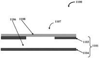
Described herein is a microfluidic device that includes a valve for selectively controlling the flow of fluid within the microfluidic device. FIG. 1A schematically illustrates a front cross-sectional view of a microfluidic valve assembly 1100, according to one embodiment. Microfluidic valve assembly 1100 includes a rigid substrate 1101 and at least one valve member 1107. The rigid substrate 1101 includes at least 1103 and 1104 layers. These layers 1103, 1104 define a fluid channel 1106 for conveying the test fluid. The valve member 1107 includes a stretchable membrane 1108, the stretchable membrane 1108 being positioned over (and optionally secured to) the layer 1103 such that the stretchable membrane 1108 is substantially separated from the fluid channel 1106. Specifically, as shown in fig. 1A, the layer 1103 may have any suitable form of through-hole(s) or opening(s) that is covered by the stretchable film 1108 such that there is a predetermined distance between the inner surface of the layer 1103 and the surface of the stretchable film 1108.
The rigid substrate 1101 is made of, for example, one of Polymethylmethacrylate (PMMA), Cyclic Olefin Copolymer (COC), Cyclic Olefin Polymer (COP), other hard polymers, other non-polymeric materials such as metal, glass, silicon, etc., or a combination thereof. The stretchable membrane 1108 is made of one or more of PDMS, polyurethane, polyester, any other soft or stretchable or elastic polymer, a stretchable polymer material, a soft or stretchable or elastic non-polymer, or a combination thereof.
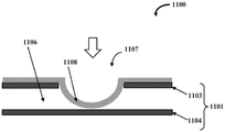
The valve member 1107 is operable based on the application of a force toward the stretchable membrane 1108. A force may be generated due to a fluid pressure differential between the fluid channel 1106 and the area behind the stretchable membrane 1108. In other embodiments, the force may be generated by an actuator, a motor, a piezoelectric device, a microelectromechanical (MEMS) device, or the like. Fig. 1B exemplarily illustrates a front cross-sectional view of the microfluidic valve assembly 1100 showing the stretchable membrane 1108 expanding to close the fluid channel 1106 upon application of an external force to the stretchable membrane 1108. The external forces are indicated by arrows in the figure.
In an alternative embodiment, the structure is the same as that shown in fig. 1 except that a section of the layer opposite the valve member is configured to protrude towards and contact the stretchable membrane to define a post member in the fluid channel. When the pressure differential between the fluid channel and the outer surface of the membrane is negative, the stretchable membrane contracts toward the control channel to allow the test fluid to flow in the fluid channel over the post member. A "post" as defined herein may be any shape or combination of shapes, or be composed of multiple structures separated from each other. In such a configuration, the PDMS membrane is generally flat and rests against a post member in a fluidic channel located below the pneumatic channel or the control channel. When the pressure in the control channel is low, the pressure of the test fluid is higher than the pressure of the control fluid, so the pressure of the test fluid pushes the PDMS membrane to deform the PDMS membrane to open, allowing the test fluid to flow over the pillar member and continue into the outlet channel. In an embodiment, the stretchable membrane of the valve member is stably positioned over the post member to close the flow of the test fluid in the fluid channel when the pressure on the side of the membrane opposite the fluid channel is greater than the pressure in the fluid channel. In other words, applying more pressure on the outside of the membrane (the side opposite to the side facing the fluid channel) allows the PDMS membrane to be positioned in a flat orientation, pressing it against the post member and blocking the flow of the test fluid. This is a "normally closed" valve configuration.
In an alternative embodiment, the structure is the same as that shown in FIG. 1A, except that there is a post structure. However, in this embodiment, the post member is not in contact with and is located below the stretchable membrane. The stretchable membrane is configured to contract and expand away from the bottom of the fluid layer to allow the flow of the test fluid in the fluid channel when a pressure difference between the fluid channel and a pressure on an outer surface of the membrane (outer, on an opposite side of the membrane from a side facing the fluid toward the fluid channel) is positive, and the stretchable membrane is configured to expand toward the upper surface of the column member to close the flow of the test fluid in the fluid channel when the pressure difference between the fluid channel and the outer surface of the membrane is negative.
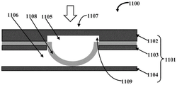
FIG. 2A schematically illustrates a front cross-sectional view of a microfluidic valve assembly 1100, according to another embodiment. As shown, the microfluidic valve assembly 1100 includes a rigid substrate 1101 and at least one valve member 1107. The rigid substrate 1101 has a plurality of layers, such as a first layer 1102, a second layer 1103, and a third layer 1104. The first layer 1102 and the second layer 1103 define a control channel 1105, and the second layer 1103 and the third layer 1104 define a fluid channel 1106. The valve member 1107 includes a stretchable membrane 1108, the stretchable membrane 1108 being positioned to seal the control channel 1105 in such a way that the stretchable membrane 110 is substantially separated from the fluid channel 1106. The rigid substrate 1101 is made of, for example, one of Polymethylmethacrylate (PMMA), Cyclic Olefin Copolymer (COC), Cyclic Olefin Polymer (COP), other hard polymers, other non-polymeric materials such as metal, glass, silicon, etc., or a combination thereof. The stretchable membrane 1108 is made from one or more of PDMS, polyurethane, polyester, Polyethylene (PE), any other soft or stretchable polymer, stretchable polymer material, or combinations thereof. The stretchable film 1108 may be a non-polymeric material that is suitably stretchable.
The valve member 1107 is operable based on a pressure (e.g., fluid pressure) difference between the fluid passage 1106 and the control passage 1105. In an embodiment, the test fluid is configured to flow through fluid channel 1106 and the control fluid is configured to flow through control channel 1105. The term "test fluid" as used herein refers to any fluid sample extracted for laboratory testing, such as a biological fluid sample, e.g., blood, and may include flowing solids, such as, but not limited to, flowing solids such as sand-like particles. In a preferred embodiment, the fluid sample is a biological fluid sample, more preferably blood. A blood sample is allowed to flow through the fluid channel 1106 to test a specific amount of blood in different channel regions. The term "control fluid" as used herein refers to any fluid or liquid, e.g., air, gas, oil, flowing solids such as sand, configured to apply pressure to the stretchable membrane 1108 of the valve member 1107 to actuate the valve member 1107, e.g., pneumatically or hydraulically.
Fig. 2B schematically illustrates a front cross-sectional view of the microfluidic valve assembly 1100 showing the stretchable membrane 1108 expanding to close the fluid channel 1106 and thus block the flow of test fluid. In the example, one or more through holes 1109 are fabricated in the first layer 1102 and the second layer 1103 to define a section or valve point for the valve member 1107. In an embodiment, as shown by the arrows in fig. 2B, when the pressure difference between the fluid channel 1106 and the control channel 1105 is negative, the stretchable membrane 1108 of the valve member 1107 expands and contacts the third layer 1104 to close off the flow of test fluid, such as blood for analysis or reagents for certain chemical reactions, in the fluid channel 1106. This arrangement is also advantageous because the valve member 1107 can easily have a different cross-section and thus be more easily sealed.
In other words, as shown by the arrows in fig. 2B, if the applied pressure of the control fluid is higher than the pressure of the test fluid, the stretchable membrane 1108 of the valve member 1107 expands to close the fluid channel 1106. In the structure, a flat PDMS layer is bonded to or simply held in place on top of the top PMMA layer. A pneumatic layer or control channel 1105 is defined on top of the PDMS. The plurality of channels are cut into first and second PMMA layers. When pneumatic pressure is applied to the PDMS layer, the PDMS layer deforms to extend into the fluid channel 1106 to block the flow of the test fluid. This configuration is a "normally open" valve configuration.
In accordance with various embodiments of the present disclosure, a PDMS substrate is fabricated in a hard polymer substrate such as PMMA, COC, or COP, instead of reshaping PDMS by molding or other techniques to form the fluidic channels 1106 and control channels 1105, as well as other features (e.g., microfluidic features, channels, wells, etc.) of the microfluidic structure. According to embodiments of the present disclosure, the rigid substrate 1101 has sections where the stretchable film 1108 or PDMS accesses the inspection fluid, for example, through holes (through holes) in an intermediate layer of PMMA over which the PDMS film is located. This design is such that when pneumatic pressure is applied to the PDMS, the stretchable membrane 1108 extends through the hole (hole) into the lower channel blocking the flow of test fluid in the lower channel.
Thus, in this embodiment, the assembly comprises at least one test fluid channel 1106 and a stretchable membrane 1108. The stretchable film 1108 may or may not have features designed into it. The design of the assembly is such that the stretchable membrane 1108 is only in contact with the test fluid in the fluid channel 1106 at certain points (e.g., valve points). Further, when the pressure on the stretchable membrane 1108 is increased or decreased, pneumatically or hydraulically or by other methods such as mechanical or electromagnetic forces, the stretchable membrane 1108 deforms such that the deformation closes or opens the fluid channels 1106. Thus, the entire assembly functions as a normally open or normally closed valve member 1107. The change in pressure may be applied to the entire assembly while deforming the stretchable membrane 1108 at multiple "valve points" and allowing multiple locations in the fluidic network to simultaneously increase or restrict the flow of the test fluid stream.
In an exemplary embodiment, the valve member 1107 operates by deformation of a flexible or stretchable membrane 1108, which flexible or stretchable membrane 1108 is in contact with the test fluid in the fluidic network only at certain specified points, such that pressure applied to the stretchable membrane 1108 causes the stretchable membrane 1108 to distort into the fluidic channels 1106 or other structures in the network, thereby blocking or restricting the path of the test fluid at the specified points in the network. Alternatively, the stretchable membrane 1108 is twisted such that the path of the test fluid is opened, increasing fluid flow.
Fig. 3A schematically illustrates a front cross-sectional view of an embodiment of a microfluidic valve assembly 1100 showing retraction of a stretchable membrane 1108 to allow flow of a test fluid, and fig. 3B schematically illustrates another front cross-sectional view of the microfluidic valve assembly 1100 of fig. 3A showing a normal, flat orientation of the stretchable membrane 1108. In an embodiment, a section of the third layer 1104 opposite the valve member 1107 is configured to protrude toward and contact the stretchable membrane 1108 to define a post member 1110 in the fluid passage 1106. When the pressure differential between the fluid pathway 1106 and the control pathway 1105 is positive, the stretchable membrane 1108 contracts toward the control pathway 1105 to allow test fluid to flow in the fluid pathway 1106 over the post member 1110. A "post" as defined herein may be any shape or combination of shapes, or be composed of multiple structures separated from each other. Preferably, the column arrangement is a combination of one or more structures of any shape protruding from the bottom surface.
In construction, the PDMS membrane is generally flat and abuts against post members 1110 in the fluidic channel 1106 below the pneumatic or control channel 1105. When the pressure in the control channel 1105 is low, the pressure of the test fluid is higher than the pressure of the control fluid, so the pressure of the test fluid pushes the PDMS membrane to deform the PDMS membrane to open, allowing the test fluid to flow over the post member 1110 and continue into the outlet channel. In an embodiment, the stretchable membrane 1108 of the valve member 1107 is stably positioned over the post member 1110 to close off the flow of test fluid in the fluid channel 1106 when the pressure differential between the fluid channel 1106 and the control channel 1105 is negative. In other words, applying more pressure in the control channel 1105 allows the PDMS membrane to be positioned in a flat orientation, pressing it against the post member 1110 and blocking the flow of the test fluid. This is a "normally closed" valve configuration.
Fig. 4A schematically illustrates a front cross-sectional view of another embodiment of a microfluidic valve assembly 1100 showing a post member 1110 having a reduced height, and fig. 4B schematically illustrates another front cross-sectional view of the microfluidic valve assembly 1100 of fig. 4B showing a stretchable membrane 1108 expanding to close a fluid channel 1106. In an embodiment, the pillar member 110 is not in contact with the stretchable film 1108 and is located below the stretchable film 1108. The stretchable membrane 1108 contracts toward the control channel 1105 to allow the test fluid to flow in the fluid channel 1106 when a pressure differential between the fluid channel 1106 and the control channel 1105 is positive, and the stretchable membrane 1108 is configured to expand toward the upper surface 1110a of the post member 1110 to close the flow of the test fluid in the fluid channel 1106 when the pressure differential between the fluid channel 1106 and the control channel 1105 is negative.
In construction, this embodiment combines aspects of the embodiments shown in fig. 1A-1B, 2A-2B, and 3A-3B, such that the valve member 1107 includes a post member 1110 that does not contact the stretchable membrane 1108. Thus, when the pressure in control channel 1105 is low, valve member 1107 opens more flexibly and verification fluid is able to flow. Valve member 1107 closes when pressure in control channel 1105 increases. In an example, the test fluid may flow flexibly when the pressure in the control passage 1105 is lower than in the case of the "normally closed" valve configuration shown in fig. 2A-2B. However, because the spacing between the stretchable membrane 1108 and the upper surface of the post member 1110 is less than the usual depth of the fluid channel 1106, it is easier to seal the stretchable membrane 1108 against the post member 1110 when pressure is applied to the control channel 1105, thereby closing the valve element 1107 more easily than in the "normally open" configuration shown in figures 2A-2B.
In an embodiment, a deeper channel depth is maintained at most of the structure except at the valve member 1107, so that as the cross-section of the path of the test fluid is larger, the flow resistance of the test fluid is smaller and the backpressure in the assembly is smaller, thus making it easier to generate or control fluid flow in the assembly. In an example, a larger cross-section can also be created by increasing the width of the fluidic channel 1106, but this takes up space in the x-y direction on the chip, which means that the chip needs to be much larger at the same fluidic backpressure, since there may be a network of very long channels on the chip. In an exemplary embodiment, each of the control channel and the fluid channel has a width of about 50 μm to about 1mm and a depth (including end points) of about 5 μm to 200 μm, but is not limited thereto. In other exemplary embodiments, the dimensions of the control channel and the fluid channel may be nano-sized or micro-sized, but are not limited thereto.
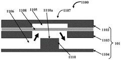
FIG. 5 schematically illustrates a cross-sectional view showing a top perspective view of another embodiment of a microfluidic valve assembly 1100. In this embodiment, the second layer 1103 includes at least two through- holes 1111a and 1111b, the through- holes 1111a and 1111b configured to facilitate communication between the fluid channel 1106 and a valve member 1107 positioned above the second layer 1103, and further to facilitate the flow of the test fluid substantially over the fluid channel 1106. Further, the cross-sectional area of the valve member 1107 is different from that of the fluid passage 1106. A through-hole 1111a passes through the second layer 1103 allowing the test fluid to be delivered through the through-hole 1111a to a PDMS valve member 1107 positioned above the second layer 1103. When the external pressure on the valve member 1107 is less than the pressure of the test fluid, the test fluid flows over the post member 1110 and back into the fluid channel 1106 through the through hole 1111 b.
In construction, the embodiment of fig. 5 follows the principles of the embodiments of fig. 1A, 1B, 2A, 2B, 3A, 3B, 4A and 4B. As exemplarily shown in fig. 5, in this embodiment, the middle PMMA layer has a through hole 1111a, and the test fluid is transferred from the lower fluid channel 1106 to a valve member 1107 made at the top side of the middle PMMA layer through the through hole 1111a, and then, the test fluid is transferred back to the main fluid channel 1106 through another through hole 1111 b. The valve member 1107 is shallower in depth than the main fluid passage 1106, and in this embodiment, there is also a column member 1110 in the middle of the valve member 1107. The PDMS layer is placed directly over and against the intermediate PMMA layer. The increased pressure applied to the PDMS layer from above causes a downward deformation of the blocking valve member 1107 or "valve channel". In an embodiment, the stretchable membrane 1108 of the valve member 1107 is embedded with magnetic beads such that the valve member 1107 is configured to be actuated via a magnetic force. In other embodiments, the valve member is configured to be actuated by electrostatic or electromagnetic forces.
In an embodiment, according to fig. 4A-4B and 5, the valve member 1107 is structured such that the depth of the control channel 1105 at the valve member 1107 is independent of the typical depth of the test fluid in the main fluid channel 1106, because it is difficult to effectively seal these types of diaphragm valves if the depth of the control channel 1105 at the valve member 1107 is large. However, if the depth of the fluid channels 1106 is generally shallow throughout the fluid network, the cross-section of the fluid channels 1106 will be smaller for a given channel width. This means that the impedance to the flow of test fluid is greater, the back pressure is greater and therefore more pressure is required to allow the test fluid to flow through the fluid network. Therefore, there is a need for an effective seal of the fluid network so that the test fluid does not leak, which is more difficult at the higher pressures and high speeds of flow of the test fluid on the chip. Thus, the microfluidic valve assembly 1100 is designed such that the depth of the control channel 1105 at the valve member 1107 is independent of the depth of the overall fluid channel 1106 so that the valve member 1107 can more easily close while maintaining a lower fluid pressure in the fluid network. Thus, the flow of the test fluid at the valve point passes through a path or layer that is independent and has a different depth than the rest of the fluid network.
In another embodiment, PDMS is poured into a cavity of a rigid polymer and allowed to cure. In another embodiment, multiple layers of PMMA or rigid and PDMS or pneumatic layers are included to enable more complex fluid routing and control. In embodiments, the microfluidic valve assembly 1100 may be applied to microfluidic chips and other structures for diagnostic applications and other applications. Further, the valve member 1107 is implemented for macro and nano applications.
Microfluidic sensing platform
The technology described herein also relates to systems and methods for detecting and/or quantifying the presence of one or more target agents. In particular, but not exclusively, one example of the utility of the present disclosure is for multi-protein biomarker disease testing, which may use a standard process that converts from manual laboratory-based protein assays to table, desktop or handheld integrated automated assays that may be used to test patients at the point of care. Some embodiments of the present disclosure will now be described in order to provide a more detailed understanding of the present disclosure, and to show how it can be applied to laboratory-based target agent quantification assays converted into an integrated desk-top or desktop format.
In one definition, an integrated system is a convenient, possibly modular, package that includes all of the elements required for precise operation. In one definition, an automated system is a system that contains multiple operationally interdependent components (which may be separated by significant physical distances) that require minimal or no interaction with an operator in order to perform optimal analysis of a test sample.
Fig. 6 represents a simple and general representation of the microfluidic chip 100. In this embodiment, the microfluidic chip 100 has an overall lateral dimension in the millimeter range. This is particularly useful for hand held inspection. In some other embodiments, the microfluidic chip 100 may have lateral dimensions other than in the millimeter range, for example in the centimeter range. The illustrated microfluidic chip 100 can be constructed in a variety of ways from a variety of materials and/or combinations of materials. For example, the microfluidic chip 100 may be constructed from solid materials including semiconductors, ceramics, metals, and polymers. It can be constructed by subtractive methods, starting with a block of material and using wet or dry chemical or mechanical methods to remove the material to form channels, holes (wells) and other structures within the material. It may also be constructed using additive methods, wherein one or several layers of one or several materials are added to the substrate 109 by using adhesion, evaporation, sputtering, Chemical Vapor Deposition (CVD) or other types of deposition on the substrate to form the microfluidic chip 100 structure. Alternatively, the following shaping method may be used for the construction: a method of bending or molding or otherwise changing the shape of the chip material. Physical forces or heating/cooling or other forces may be used to achieve this configuration. Some materials that have properties that change their physical structure over time and/or when mixed/exposed to another material may also be used to achieve this configuration. One example of such a process is an epoxy resin, which cures when mixed with some epoxy hardener. A mold may be used and the material may also be transformed into a liquid state and then allowed to cool to effect this molding process. The mold can then be physically separated from the microfluidic chip 100 in a variety of ways. Some ways will maintain the shape of the mold and the microfluidic chip 100. One example is the "lift-off process". Some other ways will maintain the shape of the microfluidic chip 100, but not the shape of the mold. One example is dissolving the mold by dipping the mold into a chemical solution. The first method is generally preferred because it allows the mold to be used multiple times to manufacture many chips, thereby reducing manufacturing costs. Combinations of these and other methods may also be used to construct the microfluidic chip 100. Some examples of common methods for constructing the microfluidic chip 100 shown in fig. 6 include: (1) photolithography on silicon or other semiconductor (or alternative material) rigid substrates, wherein some polymer is added to the material by spinning or other methods, and subsequently exposed to light or other radiation of known intensity and wavelength through a specially designed mask. The exposed polymer is then removed (or alternatively the unexposed polymer is removed) and then a material is deposited onto the substrate using sputtering or evaporation or other additive methods, or the substrate material without the polymer is removed using an etching method. The remaining polymer is then removed, leaving only an additional portion (or removed material) free of polymer. The microfluidic chip 100 structure may be constructed using successive photolithography and add/subtract steps. (2) In the case where the microfluidic chip 100 substrate is a polymer, it is heated to make the polymer soft, then pressed into a mold constructed of a hard material and allowed to cool, thereby solidifying the polymer into the desired chip design. The mold is then removed. (3) The microfluidic chip 100 substrate may be made of a material that changes its physical structure over time and/or when exposed to different materials and/or temperature changes. The material may be initially in fluid form and then poured into a mold composed of a hard or soft or flexible material and allowed to cure by exposing the fluid to a different material and/or temperature change. The mold is then removed. The materials used to construct the microfluidic chip 100 can be mixed in fluid form with any other material in liquid and powder form, if desired, to alter the physical properties of the resulting chip material. (4) The substrate of the microfluidic chip 100 may be directly shaped by other mechanical and optical methods, for example by laser-micromachining, whereby high intensity laser light is directed into a substrate made of polymer, metal, glass, silicon, ceramic, composite or other material; the substrate can be processed into a desired shape with extremely high resolution. This or a similar method can also be used to produce suitable molds for (2) and (3).
Many of the above-described methods of construction of the microfluidic chip 100 are batch construction methods, and thus the same or similar patterns can be repeated on the microfluidic chip 100, and all such structures can be fabricated by the same (or nearly the same) number of steps that are allowed to be employed in constructing a set of chip structures. This allows the microfluidic chip 100 to be manufactured to include complex structures for quantifying multiple target agents, and the production of such a microfluidic chip 100 is of similar complexity to the production of microfluidic chips 100 containing a set of structures for quantifying only one target agent.
Other embodiments of the microfluidic chip 100 may have different chip shapes and component layouts than the microfluidic chip 100 and function entirely or similarly to this particular embodiment. In this particular embodiment, the microfluidic chip 100 has magnetic dots 101 thereon to help it align properly when placed in the device for proper microfluidic chip function within the device. However, other embodiments of the microfluidic chip 100 may alternatively incorporate clips, slots, or other mechanical alignment methods or electrostatic or electromagnetic alignment methods or other forms of alignment mechanisms previously detailed in standard devices without affecting functionality, and all of these are embodiments of the present disclosure.
Different structures of the microfluidic chip 100 including various channels and wells may also be coated with various materials. During the construction of the microfluidic chip 100, the coating may be performed by evaporation or sputtering or other additive methods. Alternatively, one or more fluids may be passed through the channels or pores to deposit the coating. The coating may perform different functions, for example it may be hydrophobic or charged to prevent target agents, dust or other structures in the fluid passing through or adjacent to the various chip structures from adhering to the various surfaces of the chip structures. Alternatively, the surface of the microfluidic chip 100 structure may be hydrophilic, so that some target agent adheres thereto. Different chip structures or portions of structures may be constructed or coated so as to be hydrophobic, hydrophilic, charged, or have other characteristics desired for the chip function.
The microfluidic chip 100 has various channels for transporting fluids containing at least one target agent and any reagents, as well as other fluids that need to be added for the purposes of this disclosure, to perform its function of quantifying at least one target agent. One or more fluids containing at least one agent of interest may be delivered as a continuous flow, or may be delivered as microdroplets within a carrier liquid, or there may be any other method of delivering a fluid through a chip; by "microfluidic" is meant that the size of the structures transporting fluids on the chip is typically less than 1mm, but this designation does not refer to any particular method of fluid transport. 102 show the input channels. The input channels 102 may have various shapes and the dimensions shown in this embodiment are in the micrometer range, but in other embodiments these dimensions may be in the nanometer range or larger or smaller to continue with the chip format and dimensions. In addition, the orientation and path of the input channels 102 relative to the chip can be in many other configurations that do not affect functionality. The input channel 102 is an entry point for at least one fluid containing at least one target agent to be quantified. One example of a fluid may be water from a reservoir that is being tested against one or more target agents to determine cleanliness. Or, for example, it may be serum extracted from the blood of a patient tested for various target agents, such as protein biomarkers. Fluid may enter the input channel 102 by various methods, such as being supplied to the bore of the input channel 102, wherein the fluid may be placed into the input channel 102 from a syringe or "needle" device connected to the front of the input channel 102, which penetrates the patient's skin to draw blood directly. In this case, the blood is passed directly into the input channel or filtered or otherwise processed such that the extracted serum, plasma or other components of the whole blood are passed into the input channel. Note that it is not necessarily required to quantify the amount of fluid entering the input channel 102.
103 show the output channels. The output channels 103 may have various shapes and sizes in the micrometer range as shown in this embodiment, but in other embodiments these may be larger or smaller to continue with the chip format and size.
Furthermore, the orientation and path of the output channels 103 relative to the chip can be in many other configurations that do not affect functionality. The output channel 103 may be constructed or coated, for example, in a hydrophobic coating, to elute fluid from the output channel 103, optionally, some field or force such as electrostatic or electrical charging or mechanical force may be used to cause the fluid to actively elute when operation is desired. Similar methods and physical blocking of the output channel 103 may also be used to prevent elution of fluid from the output channel 103, if desired.
Capture wells are shown at 104. The microfluidic chip 100 includes at least one capture well 104, which may be embodied in various sizes and morphologies. The structure is a small chamber structure. This particular structure comprises, in addition to any other coating, at least one capture agent, which is placed in the capture well 104 during the construction of the capture well 104. The capture agent may be placed into the capture well 104 by a manual method including dispensing. Alternatively, it may be applied to the surface of the capture well 104 using the following method: the tip is immersed or flowed onto the fluid and then applied to the surface, or it may be printed onto the surface using an ink jet printing process or a process similar to an ink jet process, or the capture agent may be sprayed onto the surface, or the capture agent may be applied in many other well known ways described in the art. It may be administered in solid form or in fluid or aerosol form. In the latter case, it may dry to form a spot or layer in the capture well 104.
In this embodiment, the capture orifice 104 feeds from only one input channel 102. In other possible embodiments, the capture aperture 104 may feed from two or more input channels 102. Each input channel 102 is an entry point for at least one fluid. In one embodiment, several fluids may be input into the capture well 104 through only one input channel 102. In another embodiment, several fluids may be input into the capture well 104 through two or more input channels 102. In another embodiment, several fluids may be input into the capture well 104 through only one input channel 102.
In this embodiment, the capture aperture 104 has only one output channel 103. In other possible embodiments, the capture aperture 104 may feed two or more output channels 103. Each output channel 103 is at least one point of exit for excess or waste fluid. In one embodiment, several fluids may be output from the capture well 104 through only one output channel 103. In another embodiment, several fluids may be output from the capture well 104 through two or more output channels 103. In another embodiment, several fluids may be output from the capture well 104 through only one output channel 103.
In these embodiments, but not all embodiments, there is a connecting channel 105 between the capture well 104 and the detection well 108. In other embodiments, there may be zero, one, or multiple of these connection channels 108. In general, channels of the chip may be added or subtracted from the designs embodied herein, so long as fluid is still able to flow into and out of the microfluidic chip 100 and be exposed to detection and capture agents in the correct sequence.
The microfluidic chip 100 includes at least one detection well 108, and the detection well 108 may be embodied in various sizes and morphologies. The structure of the device is a small chamber structure.
This particular structure contains, in addition to any other coating, at least one detection agent that is placed in the detection well 108 during construction of the detection well 108. The detection agent may be placed in the well by manual methods, including dispensing. Alternatively, it may be coated on the surface of the detection hole 108 using the following method: the tip is immersed in or flowed onto a fluid and then applied to a surface, or an ink jet printing process or a process similar to the ink jet process or other processes may be used wherein the detection agent is sprayed onto the surface in a spray, or the detection agent may be applied in many other well known ways described in the art. It may be administered in solid form or as a carrier in the form of a fluid or aerosol. In the latter case, it may dry to form a spot or layer in the detection well 108.
In this embodiment, the detection wells 108 are not fed from any of the input channels 102. In other possible embodiments, the detection wells 108 may be fed from one input channel 102. In other possible embodiments, the detection wells 108 may be fed from two or more input channels 102. Each input channel 102 is an entry point for at least one fluid. In one embodiment, several fluids may be input to the detection well 108 through only one input channel 102. In another embodiment, several fluids may be input to the detection well 108 through two or more input channels 102. In another embodiment, several fluids may be input to the detection well 108 through only one input channel 102.
In this embodiment, the detection well 108 has zero output channels 103. In other possible embodiments, the detection aperture 108 may feed one output channel. In other possible embodiments, the detection aperture 108 may feed two or more output channels 103. Each output channel 103 is at least one point of exit for excess or waste fluid. In one embodiment, several fluids may be output from the detection well 108 through only one output channel. In another embodiment, several fluids may be output from the detection well 108 through two or more output channels 103. In another embodiment, several fluids may be output from the detection well 108 through only one output channel 103.
107 shows a blocking agent. The blocking agent 107 may have various shapes and the dimensions shown in this embodiment are in the micron range, but in other embodiments these dimensions may be larger or smaller to be continuous with the shape and size of the channel. The purpose of the blocking agent 107 is that it inhibits fluid from passing between the capture well 104 and the detection well 108 when it is placed between the two wells. When the blocking agent 107 is removed from between the two holes, fluid may pass between the two holes. In this embodiment, the blocking agent 107 is a physical object. It may be configured in different shapes, but in this embodiment is in the shape of a cuboid. The blocking agent 107 may also be composed of any material. In this embodiment, it is composed of a magnetic metal such as nickel. The blocking agent 107 may or may not be coated with various coatings or multiple coatings to allow it to better perform its function. In this embodiment, the blocker 107 is coated with a polymer that prevents metal ions from penetrating into any fluid flowing through the chip and also reduces friction and damage to the channels or pores as the blocker moves. The polymer is also hydrophobic to inhibit any fluid from passing around the blocking agent, so that the blocking agent performs its function better. The blocking agent 107 may be moved using mechanical forces, magnetic forces, electrostatic forces, or any other force utilized at a macro, micro, or smaller scale for moving an object. In this embodiment, the blocking agent 107 is moved by magnetic force generated by electromagnetism. The blocking agent 107 may be passively or actively controlled. In this embodiment, the electromagnetism and thus the movement of the blocking agent 107 is actively controlled. Alternatively, for the movement blocking agent 107 shown in this embodiment, various other means of blocking the flow of fluid may be employed, such as a valve or gate. Alternatively, the blocking agent 107 may be non-physical, e.g., electrostatic or hydrophobic or hydrophilic forces may be used to prevent or cause fluid flow, as desired. Any other known method of blocking fluid flow may be used.
In this embodiment, blocking agent 107 is contained within blocking channel 106 that is perpendicular to and intersects with connecting channel 105 between capture well 104 and detection well 108. This allows the blocking agent 107 to move to a position at the junction of the blocking channel 106 and the connecting channel 105 to block fluid flow between the capture well 104 and the detection well 108 when desired, and to move to a different position within the blocking channel 106 when fluid flow is desired so as not to block the connecting channel 105. In some embodiments, a blocking agent 107 may also be present between the input channel 102 and the capture well 104, or a blocking agent 107 may be present between the capture well 104 and the output channel 103, or a blocking agent 107 may be present at other points of the microfluidic chip 100 or between structures not shown in this embodiment. The blocking agent 107 may operate on the same or different principles. In all embodiments, the blocker 107 is able to control fluid flow throughout the chip, and thus is able to control the detection and capture agents, as exposure of the fluid containing at least one target agent to each capture agent or each detection agent is controlled. In some embodiments, the blocking agent 107 will also enable control of the amount of fluid containing at least one target agent exposed to a particular capture agent or a particular detection agent, as the blocking agent 107 will be able to block a subset of the fluid from entering a particular well or other chip structure for a particular controlled period of time. Similarly, the blocking agent 107 will be able to block other fluids containing other reagents from entering a particular well or other chip structure for a controlled period of time.
In alternative embodiments, the detection reagents may be sprayed into the capture chambers, or each reagent may be individually moved or controlled in solid form or carried in a liquid or other carrier to move around the microfluidic chip 100. Each of these and other examples is an embodiment of the principles of the present disclosure in which exposure of a fluid containing at least one target agent to each of at least one capture agent and each of at least one detection agent is individually controlled.
In this embodiment, a fluid containing at least one targeting agent flows into the input channel 101 and from there into the capture well 104. In capture well 104, at least one capture agent captures at least one target agent. In this embodiment, capture wells 104 are configured such that any capture agent remains attached to the surface of capture wells 104 even if any capture agent captures any target agent. Further, any portion of capture well 104 that does not contain a capture agent is configured to prevent the target agent or any other material flowing through capture well 104 from adhering to the surface of capture well 104. In this first step, the blocking agent blocks the connecting channel 105, preventing fluid from flowing into the detection chamber. In a second step, a standard wash solution for the biological process is washed through the capture well 104 to wash away the fluid containing the at least one target agent and any unbound target agent. In a third step, the blocking agent 107 is removed from the connecting channel 105 into a different segment of the blocking channel 106. Thus, the fluid flows into the detection hole 108. This causes the at least one detection agent in the well to mix with the fluid, and the detection agent will then pass through the capture well 104 and react with the at least one target agent bound to the at least one capture agent in the capture well 104. In some embodiments, when other blocking agents are also present at the entrance or exit of capture well 104 or other points, these blocking agents may be used at selected times to ensure that the detection agent is exposed to the target agent of capture well 104 at a particular concentration. In a fourth step, a wash solution is flowed through to wash away any unbound detection agent. In a fifth step, the presence of at least one captured target agent or alternatively the presence of at least one captured target agent is determined and the amount of captured at least one target agent is quantified (see below).
In alternative embodiments, there is an intermediate step between the fourth and fifth steps described above, such that an additional fluid containing at least one reagent flows through the microfluidic chip 100, and the reagent may bind or otherwise react with the capture, target, or detection agent or another reagent involved in the operation of the present disclosure described herein. A further washing step is then carried out to remove any unbound or other unreacted or unwanted components. In another alternative embodiment, there may be multiple steps of flowing reagents through the microfluidic chip 100 and/or multiple washing steps.
In another alternative embodiment, the at least one other reagent does not flow into the microfluidic chip 100, but is contained within another portion of the microfluidic chip 100. In another embodiment, it is contained in another part of the microfluidic chip 100 and the blocking agent 107 is present, blocking its reaction with the capture, target or detection agent until the blocking agent 107 is removed. In still other embodiments, there may be multiple reagents on the microfluidic chip 100.
In other embodiments, the steps are performed in a different order, and there may be additional or fewer or different steps as desired, where additional reagents are also present on the microfluidic chip 100, or flow to and through the microfluidic chip 100. For example, in another embodiment, the detection agent may be mixed with a fluid containing at least one target agent. In other embodiments, the reagents may be mixed.
In various other embodiments, the shape, size, and connections between the various components of the microfluidic chip 100 as set forth in these embodiments will be different. Additional reagents may also be required and may be included on the microfluidic chip 100 or flowed onto the microfluidic chip 100 or a combination of these.
In some embodiments, the microfluidic chip 100 will also include sensing structures to form part of a quantification system for bound target agents. These sensing structures are preferably, but not necessarily, located in the capture well 104 or just below and/or above the capture well 104. This allows for immediate quantification upon capture of the target agent without further processing. Examples of such sensing structures include (but are not limited to):
(1) an oscillation sensor, which is a structure on a chip that is caused to oscillate. The frequency of oscillation of the structure depends on the mass, so the frequency of oscillation varies according to the amount of any material attached to the oscillating sensor, and this variation of oscillation is related to the concentration of the target agent. Examples of such sensors include miniature Quartz Crystal Microbalances (QCMs) and Surface Acoustic Wave (SAW) structures;
(2) an electrochemical sensor, whereby a reaction with a reagent in the fluid produces an electrical signal related to the concentration of the target agent. A typical electrochemical sensor consists of a sensing electrode and a counter electrode separated by a thin layer of insulating material. Examples of such sensors include potentiometric biosensors;
(3) an electronic sensor, whereby interaction of the reagent with some component of the sensor causes a change in an electrical characteristic of the portion of the sensor, whereby the change in the characteristic is related to the concentration of the target agent. Examples of such sensors include Field Effect Transistors (FETs), whereby binding of the agent to the gate of the FET changes the resistance between the source and drain of the FET;
(4) a hall effect sensor, which is a transducer that changes its output voltage in response to a magnetic field. The output voltage variation is related to the target agent concentration;
(5) an optical sensor, whereby light absorption or emission occurs in relation to the concentration of the target agent. This light absorption may be due to a color change of the substrate caused by a chemical reaction of the reagent with other reagents, such as enzymes, which may be measured, for example, by spectrophotometry; or directly absorb or emit light of a particular wavelength or wavelengths due to the optical properties of the agent or due to the agent having a fluorescent or light-emitting structure attached thereto. Examples of such sensors include enzyme-linked immunosorbent assays (ELISAs) and photoluminescent sensors;
(6) an optical sensor that utilizes an alternative method of optical detection whereby a change in the optical signal is related to the concentration of the target agent. Examples of such optical detection systems include interferometry or near-field microscopy (measurement of changes in evanescent waves); and
(7) mechanical sensors, whereby a deformation of the physical shape of the sensor due to additional stress caused by the attachment of reagents is caused. Such deformation in relation to the concentration of the target agent may be detected by, for example, optical interferometry or a change in an electrical, mechanical, magnetic or structural property of the material. Examples of such sensors include cantilever-based sensors and piezoelectric sensors.
For completeness, some examples of fluids containing a target agent include: (1) any solution or suspension for commercial or non-commercial applications containing the particular inorganic chemical to be quantified, e.g. for the chemical industry; (2) any solution or suspension containing a particular organic chemical for commercial or non-commercial applications; (3) any biological fluid; (4) any fluid from a human or animal, but especially blood, urine, mucus, saliva and cerebrospinal fluid; (5) any fluid from other biological organisms, including plants, fungi, bacteria or archaea; (6) any fluid from any other biological entity; (7) a fluid containing a product from the food industry; water from rivers, oceans, rain, wastewater plants, or other sources.
For completeness, some examples of targeting agents include: (1) proteins (natural and synthetic), including antibodies, antigens, enzymes and other proteins; or a structure comprising a protein; (2) peptides (natural and synthetic); (3) amino acids or structures comprising amino acids (natural and synthetic); (4) DNA (natural and synthetic); (5) RNA (natural and synthetic); (6) nucleic acids or structures comprising nucleic acids (natural and synthetic); (7) a saccharide (saccharoide) or a structure comprising a saccharide (natural and synthetic); (8) lipids (lipids) or structures comprising lipids (natural and synthetic); (9) other biomolecules and structures including biomolecules (natural and synthetic); (10) whole or partial cells or cell populations (with or without inclusion of acellular structures); (11) any cell-containing structure; (12) any other biological structure; any non-biochemical structure having a specific pattern that can be recognized by a capture agent and used to bind and immobilize a target agent.
For completeness, some examples of capture agents include: (1) antibodies produced using whatever means, including monoclonal antibodies, polyclonal antibodies or antibodies produced by pure chemical synthesis; (2) aptamers that occur naturally, are produced using biological methods, or are produced using synthetic chemical methods, or any other natural or synthetic method; (3) nucleic acid strands or structures (natural and synthetic); (4) peptide chains or structures (natural and synthetic); (5) a molecule or other chemical comprising a charge pattern complementary to the charge pattern on the target agent; (6) a molecule or other chemical comprising a pattern of hydrophobic or hydrophilic regions that is complementary to a pattern on a target agent; (7) molecules or other chemicals that include a pattern of dipoles, quadrupoles, or other higher order poles that is complementary to such a pattern on the target agent; (8) a molecule or other chemical comprising a pattern of magnetic regions complementary to a magnetic pattern on a target agent; (9) inorganic materials may be naturally occurring or prepared using any synthetic method or in other ways. Examples of such inorganic structures include functionalized single-walled and multi-walled carbon nanotubes, silicon polymers (e.g., having a specific charge pattern), and nanoparticle composites; structures (including cells, tissues, and other organic and inorganic structures) including any of the above as substructures, components, or elements.
For completeness, some examples of detection agents include: (1) antibodies produced using whatever means, including monoclonal antibodies, polyclonal antibodies or antibodies produced by pure chemical synthesis; (2) aptamers that occur naturally, are produced using biological methods, or are produced using synthetic chemical methods, or any other natural or synthetic method; (3) nucleic acid double and single stranded or structures (natural and synthetic); (4) peptide chains or structures (natural and synthetic); (5) a molecule or other chemical comprising a charge pattern complementary to the charge pattern on the target agent; (6) a molecule or other chemical comprising a pattern of hydrophobic or hydrophilic regions that is complementary to a pattern on a target agent; (7) a molecule or other chemical comprising a pattern of hydrophobic or hydrophilic regions that is complementary to a pattern on a target agent; (8) molecules or other chemicals that include a pattern of dipoles, quadrupoles, or other higher order poles that is complementary to a pattern on the target agent; (9) a molecule or other chemical comprising a pattern of magnetic regions complementary to a pattern of magnetic regions on a target agent; (10) inorganic materials may be naturally occurring or prepared using any synthetic or other method. Examples of such inorganic structures include functionalized single-walled and multi-walled carbon nanotubes, silicon polymers (e.g., having a specific charge pattern), and nanoparticle composites; and (11.) structures (including cells, tissues and other organic and inorganic structures) that include any of the above as substructures, components or elements.
Examples of other reagents include secondary antibodies that aid in the detection of the target agent by binding to a detection antibody (or other reagent) that binds to the target agent. The detection antibody or secondary antibody may have a color change that binds to the enzyme to cause a reagent "developer" similar to standard ELISA methods, or may have a fluorescent or electrochemiluminescent region or other region associated with the detection mechanism of choice. It is also possible that multiple enzymes are attached to a single detection antibody or secondary antibody. Methods for their binding include those common in the art, such as streptavidin-biotin binding. Other reagents may be particles, including nanoparticles, that bind to the target agent or detection agent. In one embodiment, such nanoparticles are used to increase the mass bound to the mass sensor for each bound target agent by a set amount to enhance the sensitivity of the mass sensor (e.g., the oscillating sensor or mechanical sensor system described above). In various embodiments, magnetic nanoparticles are used to increase the output voltage change per unit magnetic field in a Hall effect sensor. Other agents may be organic and inorganic chemicals that bind to the target agent. In one embodiment, such chemicals bind to the target agent and promote oxidation of the metal film, thereby producing an enhanced change in the electrical signal detected in the electronic sensor.
The microfluidic chip 100 is formed of "N" sensing structures and their corresponding wells and channels needed for quantification of the target agent; i.e. the system is formed by an "N" quantization system. This is indicated by one or more quantization systems 110 in fig. 6. "N" can be any number between 1 and infinity; i.e., a chip may be made up of any number of quantization systems 110. For example, a chip may consist of one quantization system 110. In another example, a chip may be formed by ten quantization systems 110. In another example, the sensor may be formed by one hundred quantization systems 110. All sensing structures and quantification systems 110 are preferably identical. For example, in one embodiment, all quantization systems 110 include a sensing structure that is an oscillating structure. For example, in various embodiments, all of the quantification systems 110 include a sensing structure that is a type of electrochemical sensor. However, in some embodiments, the quantization system 110 may be different. In an example of such an embodiment, half of the quantification system 110 comprises a sensing structure that may be an oscillating structure, and the other half of the quantification system 110 comprises a sensing structure that may be a type of optical sensor. In a different example of such an embodiment, half of the quantification system 110 comprises a sensing structure that may be an oscillating structure, and the other half of the quantification system 110 comprises a sensing structure that may be a type of electrochemical sensor. Each quantification system 110 is for quantifying a different target agent. In some embodiments, two or more quantification systems 110 may be used to quantify the same target agent for comparison, however the measurements made by the quantification systems 110 are independent of each other; i.e., the use of several quantification systems within a chip to quantify the same target agent, increases the confidence in the results by repeatability, but does not add additional sensitivity, and does not need to do so.
In various other embodiments, the position of the quantification system 110 within the microfluidic chip 100 is different from the position shown in fig. 6. For example, in one embodiment, a plurality of quantization systems 110 may be placed adjacent to one another in a linear direction, forming a linear array of quantization systems 110. In another embodiment, one or more quantization systems 110 may be placed adjacent to each other along two linear directions, forming a two-dimensional array. For example, in another embodiment, the quantization system 110 may be placed at random discrete locations within the chip.
Fig. 7 shows a microfluidic chip 200 substantially similar to the microfluidic chip 100 shown in fig. 6. The microfluidic chip 200 further comprises an input well 202 feeding an input channel 203. The input aperture 202 may have various shapes and sizes shown in this embodiment are in the mm range, but in other embodiments these sizes may be in the cm range or 100 μm range or larger or smaller to continue with the chip format and size. Fluid may be placed into the input well from a syringe or "needle stick" device attached to the front of the input channel 203, where the syringe or "needle stick" device penetrates the skin of the patient to draw blood directly. In this embodiment, only one input aperture 202 feeds all input channels 203 directly, without additional microfluidic control. However, in some embodiments, there may be more than one input aperture 202 selectively feeding at least one input channel 203. For example, in one such embodiment, there is one input aperture 202 feeding all input channels 203. For example, in various embodiments, there are two input apertures 202 feeding each half of the input channel 203. In a third different example of such an embodiment, there are two input apertures 202 feeding all input channels 203 alternately. The embodiment shown in fig. 7 also includes an output "waste" aperture 205 fed from the output channel 204. The output aperture 205 collects excess fluid or waste generated during the quantification process. Preferably, only one output aperture 205 contains all of the excess fluid and waste produced. In less preferred embodiments, the microfluidic chip 200 may contain more than one output well 205. In the embodiment shown in fig. 7, there is only one output aperture 205 fed directly from all output channels 204, without additional microfluidic control. However, in some embodiments of the present disclosure, there may be more than one output aperture 205 selectively fed from at least one output channel 204. The microfluidic chip 200 can be designed in many different ways using any combination of numbers of input wells 202 and output wells 205.
Fig. 8 illustrates a detailed view of a portion of the quantization system 300 shown in fig. 6, in accordance with an embodiment of the present disclosure. Shown is an input channel 301, which corresponds to input channel 102; an output channel 302 corresponding to the output channel 103; a capture well 303, corresponding to capture well 104; a connection channel 304 corresponding to the connection channel 105; a blocking channel 305 corresponding to the blocking channel 106; a blocking agent 306 corresponding to blocking agent 107; and a detection hole 307 corresponding to the detection hole 108.
Fig. 9 shows an alternative embodiment of a quantification system 400, in which system 400 there is a blocking agent 410 between the input channel 408 and the capture well 403, a blocking agent 412 between the capture well 403 and the output channel 402, and a blocking agent 406 between the capture well 403 and the detection well 407. Blockers 406, 410 and 412 may operate controllably on the same or different principles. Also shown are input channel 401 between input channel 408 and capture well 403, connecting channel 404 between detection well 407 and capture well 403, and blocking channels 409 and 411 associated with blocking agents 410 and 412, respectively.
Fig. 10 embodies a loading device 500 into which the microfluidic chip 100, 200 as described above is inserted to determine the presence of or quantification of at least one target agent. The loading device 500 is adapted to control the flow and mixing of fluids within the microfluidic chip 100, 200 and to control the sensor. In this embodiment, the loading device 500 has an overall lateral dimension in the cm range. This is particularly useful for hand held inspection. In some other embodiments, the loading device 500 may have a different lateral dimension than the cm range, such as in the dm range. This is more suitable for bench-top inspection. In this embodiment, there is a positioning mechanism 501 for ensuring the correct position on the insertion device when the microfluidic chip 100, 200 is placed on or in the loading device 500. Such mechanisms may be purely mechanical or use many different standard and well known methods of operation. In this particular embodiment, there are magnetic dots corresponding to the magnetic dots on the microfluidic chip 100, 200 as shown at 101 in fig. 6, thus attracting the corresponding dots on the microfluidic chip, ensuring that the microfluidic chip is properly inserted in place on the device. In this particular embodiment, there is also connection electronics 502 that connects any electronic connections or structures on the microfluidic chip (e.g., any electronically operated sensing elements) to the control electronics in the device. Depending on the sensing system used to detect the presence of or quantify the amount of the at least one target agent, a detector 503 may be present in the apparatus. This would include the sensing elements and any other structure required for sensing operation. For example, in one embodiment, the detection operates similarly to an ELISA system, whereby color changes or fluorescent reactions in portions of the microfluidic chip are detected or measured, and then the detector includes a light generating element that illuminates the chip and a light sensing system that can measure changes in light due to absorption or emission in the microfluidic chip. In one embodiment of the system, there is also a control mechanism between the light generating elements that controls the exposure and non-exposure of different areas of the microfluidic chip 100, 200 to light from the light generating elements and allows different areas of the microfluidic chip to be exposed, not exposed, or to varying degrees to light from the light generating elements at different time periods. In one embodiment, the control mechanism is a liquid crystal panel similar to those used in liquid crystal displays. In another embodiment, there are a plurality of light generating elements. In another embodiment, there are a plurality of light generating elements, and each light generating element exposes only a specific area of the microfluidic chip. In another embodiment, this exposure of different portions of the microfluidic chip by separate optical elements is accomplished by an LED panel similar to that which operates in LED television displays.
In the embodiment shown in fig. 10, there is also an embedded processing unit/electronics 504. This includes at least one microcontroller or at least one microprocessor, memory and other such standard electronics that are known to be used for the purpose of processing data from any sensing components on the device, control of active components on the device (if any), and any other functions of the device (if desired). In this embodiment there is one processing unit. In alternative embodiments, there may be multiple processing units.
This embodiment of the device comprises a housing 505, the housing 505 being a standard enclosure enclosing the electronics and microfluidic chip and also preventing physical particles, light or other unwanted foreign objects from contaminating the interior of the device. In this embodiment, there is also an insertion slot 506 through which the microfluidic chip is placed into the loading device 500. There may be other standard electronics or connections 507 on the device to allow normal or enhanced operation thereof.
Fig. 11 shows an alternative embodiment in which the loading device 600 has no on-board processing unit, but the device is connected by a wired connection 604 to a separate at least one smart structure 605, such as, but not limited to, a computer, laptop, tablet device, mobile phone or custom infrastructure where the processing takes place, and a microfluidic chip is inserted into the loading device 600 to quantify the target agent. The wired connection 604 is preferably made by means of a USB/miniUSB/microUSB cable. Alternatively, the wired connection 604 is made through RS232, GPIB or a different type of data cable. The smart fabric 605 is preferably connected to the internet through a mobile network connection or through Wi-Fi. In an alternative embodiment, the loading device 600 is wirelessly connected to the at least one smart structure 605 (where the processing occurs) via bluetooth or Wi-Fi or an alternative wireless data connection. In an alternative embodiment, the loading device 600 is connected via the internet or other network to a separate at least one intelligent structure where the processing occurs.
Any combination of standard on-board and off-board electronics for data acquisition, processing, and device control are embodiments of the present disclosure.
Fig. 12 is an embodiment of a loading device 700. There is a positioning system on the loading device to ensure that the microfluidic chip is placed in the correct position when loaded onto the loading device 700. This can be done in many different standard ways, including any of the known ways disclosed. In this embodiment, magnetic dots 701 are used that will attract corresponding magnetic dots on the microfluidic chip as shown at 101 in fig. 6. In this embodiment, there is an insertion slot 702, and a microfluidic chip is placed in the insertion slot 702. In other embodiments, the microfluidic chip may simply be placed on top of the loader, or the insertion slot may have alternative dimensions or geometries. In further embodiments, an auto-load device may be present to load chips from a chip stack or other chipset. In this embodiment, there is only one insertion slot, in which the microfluidic chips are placed one after the other. In other embodiments, there may be more than one insertion slot 702 for loading multiple microfluidic chips into different slots simultaneously. In yet another embodiment, there may be one insertion slot 702 into which a plurality of microfluidic chips are simultaneously inserted. In yet another embodiment, there may be more than one insertion slot 702 into which multiple microfluidic chips are placed simultaneously. In this embodiment, various "inks" are placed in micro ink holes 705 in the loading device 700. By "ink" herein is meant a fluid containing at least one capture or detection agent. The various "inks" may contain different capture or detection agents. In other embodiments of the loading device 700, there may be other ways to load "ink," such as in an alternative embodiment, it may be loaded first into a cartridge that is then placed in the loading device. In another embodiment, the at least one capture agent or the at least one detection agent may be placed in the device in solid form and the device may mix them internally into a fluid. These alternative methods for loading "ink" are all various embodiments of the present disclosure. In this embodiment, "ink" passes through the printing tip 703, and the printing tip 703 contacts a surface or near a surface to deposit ink at a particular location. The positioning of at least one tip 703 is set in this embodiment and the microfluidic chip is loaded underneath it in order to have "ink" placed or "printed" so that the tip 703 only needs to be moved in the vertical up and down (z) direction. In an alternative embodiment, the tip 703 may also be moved horizontally in the in-plane (x-y) direction so that the printing position may be changed between runs and even between individual microfluidic chips. In other embodiments, the printing mechanism is changed so that ink is ejected from tip 703 to the correct location on the microfluidic chip. In other embodiments, the number of tips is different from the number of "inks", rather, the same tip has multiple "inks" flowing therethrough, or the same "ink" flows through multiple tips. In different embodiments, the tip 703 may be of a completely different size or geometry, including just being a hole (hole) in a hole (well). In other embodiments, rather than ink flowing from the well into the tip 703, the tip 703 is dipped into the well so that some ink adheres thereto, and such ink is then placed on the microfluidic chip. In other embodiments, the tip 703 is not present, but some alternative method such as manipulating an electrostatic or electromagnetic field or hydrophilic or hydrophobic forces is used to move the "ink" from one or more wells to the microfluidic chip. There are also embodiments that comprise various combinations of these alternative embodiments. Any system in which the loading device contains a method for printing at least one "ink" to a specific location on the microfluidic chip is an embodiment of the present disclosure. Other configurations may also be used to form part of the printing system for the movement or transport of "ink" -in this embodiment, connecting channel 707. As well as on-board electronics 704 and other connections. This includes at least one microcontroller or at least one microprocessor of the standard, memory, and other such known standard electronics for processing the processed data from any sensing components on the loader 700, control of active components on the loader, and any other functions of the loader (if desired). In this embodiment there is one processing unit. In an alternative embodiment, there are multiple processing units. In this embodiment, there is a wired connection 706 to the computer. In an alternative embodiment, there is no on-board processing unit, but the system is connected by a wired connection 706 to at least one device or computer that is separate from where processing occurs. In an alternative embodiment, the connection is wireless through a Bluetooth or Wi-Fi wireless connection or an alternative wireless connection to at least one device or computer that handles the separation that occurs. In another embodiment, it is connected through the Internet or other network to at least one device or computer that is separate from where the processing occurs. Any combination of standard on-board and off-board electronics for data acquisition, processing, or loading device control is an embodiment of the present disclosure.
For purposes of illustration, two example embodiments of the present disclosure will now be described.
In a first exemplary embodiment, a microfluidic chip made of polymer, glass or other transparent material and containing an "N" quantification system is used. All capture wells are coated with at least one capture antibody. In this particular embodiment, there are "N" capture wells, one for each quantification system. In this particular embodiment, each capture well is coated with a different capture antibody. All detection wells are coated with at least one detection antibody. In this particular embodiment, there are "N" detection wells, one for each quantification system. In this particular embodiment, each detection well is coated with a different detection antibody.
In this particular embodiment, there is one connecting channel between each pair of capture and detection wells. In this particular embodiment, there is an actively controlled (active controlled) blocker at each connecting channel. In this particular example, all of the blocking agents initially block the connecting channel. In this particular embodiment there is one input aperture. In this particular embodiment there is an output aperture. In this particular embodiment, there is an input channel connecting the input aperture and the capture aperture. In this particular embodiment, there is an output channel connecting the capture well and the output well. Both the capture and detection wells are coated with capture and detection antibodies using a loading device. The microfluidic chip is introduced into the device. In this particular embodiment, the device has a pixelated LED light below the capture aperture. In this particular embodiment, the device has a light detector above the capture well. In this particular embodiment, the device has embedded electronics to control the LED lights and detectors.
In this particular embodiment, the fluid sample to be analyzed (possibly containing the target antigen) is deposited in the input well. The fluid sample to be analyzed flows through the input channel, submerges the capture well and exits through the output channel. The target antigen (if present) in the sample to be analyzed specifically binds to the capture antibody immobilized on the surface of the capture well. A volume of cleaning fluid (e.g., buffer) is deposited in the input well, flows through the input channel, floods the capture well and exits through the output channel, removing loose agent deposited on the surface of the capture well. The blocking agent is now switched to unblock the connecting channel. A known amount of carrier liquid is deposited in the input well. The carrier fluid flows through the input channel, submerging the capture wells, through the connecting channel, and submerging the detection wells. The detection antibody is transported by the fluid by diffusion and binds to the target antigen (if present) immobilized on the surface of the capture well. A volume of cleaning fluid (e.g., buffer) is deposited in the input well, flows through the input channel, floods the capture well and exits through the output channel, removing loose agent deposited on the surface of the capture well. A liquid containing an enzyme-linked secondary antibody is deposited into the input well, flows through the input channel, flows through the capture well and exits through the output channel. The enzyme-linked secondary antibody binds to the detection antibody (if present). A volume of cleaning fluid (e.g., buffer) is deposited in the input well, flows through the input channel, floods the capture well and exits through the output channel, removing loose agent deposited on the surface of the capture well. A known amount of developer is deposited in the input aperture, flows through the input channel and floods the capture aperture. The color change is produced in proportion to the amount of target antigen present in the fluid sample to be analyzed. The LED lamps are sequentially turned on/off. The readings from the detector are used to detect the concentration of "N" different antigens present in the fluid sample to be analyzed.
In a second example embodiment, a microfluidic chip made of silicon containing an "N" quantification system was used. All capture wells are coated with at least one capture antibody. In this particular embodiment, there are "N" capture wells, one for each quantification system. In this particular embodiment, each capture well is coated with a different capture antibody. In this particular embodiment, the bottom of the capture well is the top electrode of an oscillating sensor that has been integrated with (or built into) a silicon chip, such as a small form factor quartz crystal microbalance. All detection wells are coated with at least one detection antibody. In this particular embodiment, there are "N" detection wells, one for each quantification system. In this particular embodiment, each detection well is coated with a different detection antibody. In this particular embodiment, there is one connecting channel between each pair of capture and detection wells. In this particular embodiment, there is one actively controlled blocker at each connecting channel. In this particular example, all of the blocking agents initially block the connecting channel. In this particular embodiment there is one input aperture. In this particular embodiment there is an output aperture. In this particular embodiment, there is an input channel connecting the input aperture and the capture aperture. In this particular embodiment, there is an output channel connecting the capture well and the output well. Capture and detection wells capture and detection antibodies are coated using a loading device. The microfluidic chip is introduced into the device. In this particular embodiment, the device has an electrical connection below the capture well to drive the oscillation sensor. In this particular embodiment, the device has embedded electronics to measure the frequency change of the oscillation sensor.
In this particular embodiment, a fluid sample to be analyzed (possibly containing the target antigen) is deposited in the input well. The fluid sample to be analyzed flows through the input channel, submerges the capture well and exits through the output channel. The target antigen (if present) in the sample to be analyzed specifically binds to the capture antibody immobilized on the surface of the capture well. A volume of cleaning fluid, such as a buffer, is placed into the input well, flows through the input channel, floods the capture well and exits through the output channel, removing loose agents deposited on the surface of the capture well. The blocking agent is now switched to unblock the connecting channel. A known amount of carrier liquid is deposited in the input well. The carrier fluid flows through the input channel, submerging the capture wells, through the connecting channel, and submerging the detection wells. The detection antibody is transported by diffusion through the fluid and binds to the target antigen (if present) immobilized on the surface of the capture well. A volume of cleaning fluid, such as a buffer, is placed into the input well, flows through the input channel, floods the capture well and exits through the output channel, removing loose agents deposited on the surface of the capture well. A fluid comprising gold nanoparticles bound to a secondary antibody is deposited in the input well, flows through the input channel, flows through the capture well and exits through the output channel. The gold nanoparticle-linked antibody binds to the detection antibody (if present). A volume of cleaning fluid (e.g., buffer) is deposited in the input well, flows through the input channel, floods the capture well and exits through the output channel, removing loose agents and particles deposited on the surface of the capture well. The oscillating sensor in turn activates and the device with embedded electronics reads the frequency shift. The readings from the sensors are used to detect the concentration of "N" different antigens present in the fluid sample to be analyzed.
Thus, a microfluidic device has been described that includes a valve and a microfluidic sensing platform for selectively controlling the flow of fluid within the microfluidic device. Although embodiments have been described with reference to specific example embodiments, it will be evident that various modifications and changes may be made to these example embodiments without departing from the broader spirit and scope of the application. For example, such changes may include, but are not limited to, changes in the forces used to actuate the valve membrane, changes in the rigid and soft materials, and changes and/or additions to other fluid or control layers. The specification and drawings are, accordingly, to be regarded in an illustrative rather than a restrictive sense.
The present disclosure is also particularly useful in methods of therapeutically or prophylactically treating a subject. The subject is preferably an animal, more preferably a mammal, even more preferably a human. Although it is envisaged that the present disclosure will also apply to veterinary disciplines.
The disclosures of each patent, patent application, and publication cited herein are hereby incorporated by reference in their entirety.
Citation of any reference herein shall not be construed as an admission that such reference is available as "prior art" to the present application.
Throughout the specification, the aim has been to describe the preferred embodiments of the disclosure without limiting the disclosure to any one embodiment or specific collection of features. Thus, those skilled in the art will recognize, in light of the present disclosure, that various modifications and changes may be made in the specific embodiments illustrated without departing from the scope of the invention. All such modifications and variations are intended to be included herein within the scope of the appended claims.
Claims (10)
1. A microfluidic valve assembly comprising:
a rigid substrate having at least two adjacent layers defining a fluid channel, wherein the at least two adjacent layers include a first layer and a second layer;
at least one valve member positioned adjacent to the second layer;
at least two through-holes in the second layer configured to facilitate communication between the fluid passage and the valve member to facilitate flow of a test fluid substantially adjacent the fluid passage; and
a post member, wherein the test fluid flows over the post member when the external pressure on the valve member is less than the pressure of the test fluid,
wherein the valve member is fabricated on a top side of the second layer.
2. The microfluidic valve assembly of claim 1, wherein the test fluid flows back to the fluid channel through the through-hole.
3. The microfluidic valve assembly of claim 1, wherein a cross-sectional area of the valve member is different than a cross-sectional area of the fluid channel.
4. The microfluidic valve assembly of claim 1, wherein the valve member is shallower in depth than the fluid channel.
5. The microfluidic valve assembly of claim 1, wherein the stretchable membrane of the valve member is embedded with conductive or magnetic beads, and wherein the valve member is configured to be actuated by an electrical or magnetic force.
6. The microfluidic valve assembly of claim 1, wherein the valve member is above the second layer.
7. The microfluidic valve assembly of claim 1, wherein the test fluid flows substantially over the fluid channel.
8. The microfluidic valve assembly of claim 1, wherein the post member is intermediate the valve members.
9. The microfluidic valve assembly of claim 1, wherein a depth of a control channel at the valve member is independent of a depth of the fluid channel such that the valve member closes more easily while maintaining a lower fluid pressure in the fluid network.
10. A method of delivering fluid on the microfluidic valve assembly of claim 1, the method comprising:
flowing a test fluid through the fluid channel within the rigid substrate; and
flowing the test fluid through the at least two through-holes in the second layer to facilitate flow of test fluid substantially adjacent the fluid channel, wherein the test fluid flows over the post member when an external pressure on the valve member is less than a pressure of the test fluid.
Applications Claiming Priority (6)
| Application Number | Priority Date | Filing Date | Title |
|---|---|---|---|
| US201562155470P | 2015-04-30 | 2015-04-30 | |
| US62/155,470 | 2015-04-30 | ||
| US201562156368P | 2015-05-04 | 2015-05-04 | |
| US62/156,368 | 2015-05-04 | ||
| PCT/EP2016/059660 WO2016174230A1 (en) | 2015-04-30 | 2016-04-29 | Microfluidic valves and devices |
| CN201680039266.4A CN108136388A (en) | 2015-04-30 | 2016-04-29 | Microfluidic valve and device |
Related Parent Applications (1)
| Application Number | Title | Priority Date | Filing Date |
|---|---|---|---|
| CN201680039266.4A Division CN108136388A (en) | 2015-04-30 | 2016-04-29 | Microfluidic valve and device |
Publications (1)
| Publication Number | Publication Date |
|---|---|
| CN114893585A true CN114893585A (en) | 2022-08-12 |
Family
ID=55948812
Family Applications (2)
| Application Number | Title | Priority Date | Filing Date |
|---|---|---|---|
| CN202111648713.5A Pending CN114893585A (en) | 2015-04-30 | 2016-04-29 | Microfluidic valve and device |
| CN201680039266.4A Pending CN108136388A (en) | 2015-04-30 | 2016-04-29 | Microfluidic valve and device |
Family Applications After (1)
| Application Number | Title | Priority Date | Filing Date |
|---|---|---|---|
| CN201680039266.4A Pending CN108136388A (en) | 2015-04-30 | 2016-04-29 | Microfluidic valve and device |
Country Status (7)
| Country | Link |
|---|---|
| US (2) | US20180093269A1 (en) |
| EP (1) | EP3288681A1 (en) |
| JP (3) | JP2018522206A (en) |
| CN (2) | CN114893585A (en) |
| HK (1) | HK1250681A1 (en) |
| SG (1) | SG11201708866YA (en) |
| WO (1) | WO2016174230A1 (en) |
Families Citing this family (15)
| Publication number | Priority date | Publication date | Assignee | Title |
|---|---|---|---|---|
| WO2020041342A2 (en) * | 2018-08-20 | 2020-02-27 | Vanderbilt University | Cartridge systems, capacitive pumps and multi-throw valves and pump-valve systems and applications of same |
| CN109012769B (en) * | 2018-07-11 | 2020-01-21 | 西安交通大学 | Micro-fluidic liquid drop generation device and method based on surface acoustic wave |
| CN110857743B (en) * | 2018-08-22 | 2020-10-16 | 厦门大学 | Liquid flow guide valve for micro-fluidic chip and micro-fluidic chip |
| CN109622083A (en) * | 2019-01-24 | 2019-04-16 | 京东方科技集团股份有限公司 | A kind of microfluidic system and preparation method thereof |
| EP3694227A1 (en) * | 2019-02-07 | 2020-08-12 | Oticon A/s | A hearing device comprising an adjustable vent |
| CN109967144B (en) * | 2019-03-25 | 2021-02-19 | 宁波美康盛德生物科技有限公司 | Dry chemical analyzer for detecting microfluidic chip and microfluidic chip |
| EP3763439A1 (en) * | 2019-07-12 | 2021-01-13 | Curiosity Diagnostics sp. z o.o | Microfluidic chip and valve, production process and uses |
| CN110568202B (en) * | 2019-09-12 | 2022-05-24 | 重庆科技学院 | Automatic sample separation constant volume immunofluorescence quantitative rapid detection micro-fluidic chip |
| CN110605147B (en) * | 2019-09-18 | 2021-04-06 | 重庆大学 | Liquid crystal-based temperature control micro valve and single-stage and multi-stage control system thereof |
| CN110597328B (en) * | 2019-09-18 | 2021-04-23 | 重庆大学 | Flow cooperative control system based on liquid crystal temperature control micro valve |
| EP3839467B1 (en) * | 2019-12-19 | 2023-06-14 | Paris Sciences et Lettres | Microfluidic or millifluidic chip comprising a pressure sensing unit using colour-switching hydrogels |
| TW202128281A (en) * | 2019-12-30 | 2021-08-01 | 美商伊路米納有限公司 | Actuation systems and methods for use with flow cells |
| CN113967486A (en) * | 2020-07-22 | 2022-01-25 | 京东方科技集团股份有限公司 | Centrifugal micro-fluidic chip |
| CN112067533B (en) * | 2020-09-26 | 2024-01-19 | 宁波大学 | Single cell mass spectrometry system and method |
| CN114768894B (en) * | 2021-01-22 | 2023-08-11 | 中国科学院上海微系统与信息技术研究所 | Detection chip and detection method |
Family Cites Families (8)
| Publication number | Priority date | Publication date | Assignee | Title |
|---|---|---|---|---|
| US6899137B2 (en) * | 1999-06-28 | 2005-05-31 | California Institute Of Technology | Microfabricated elastomeric valve and pump systems |
| ATE374162T1 (en) * | 2000-11-02 | 2007-10-15 | Biacore Ab | VALVE TO WHICH A MICROFLUID LIQUID TRANSPORT ARRANGEMENT IS INTEGRALLY ASSIGNED |
| WO2004061085A2 (en) * | 2002-12-30 | 2004-07-22 | The Regents Of The University Of California | Methods and apparatus for pathogen detection and analysis |
| US20080038714A1 (en) * | 2005-11-02 | 2008-02-14 | Affymetrix, Inc. | Instrument to Pneumatically Control Lab Cards and Method Thereof |
| WO2008036997A1 (en) * | 2006-09-28 | 2008-04-03 | Fluidyx Pty. Limited | A system and method for controlling fluids within a microfluidic device |
| WO2011107996A1 (en) * | 2010-03-03 | 2011-09-09 | The Secretary, Department Of Atomic Energy, Govt. Of India | A flexible magnetic membrane based actuation system and devices involving the same. |
| EP2479466A1 (en) * | 2011-01-21 | 2012-07-25 | Biocartis SA | Micro-Pump or normally-off micro-valve |
| KR20130069304A (en) * | 2011-12-15 | 2013-06-26 | 삼성전자주식회사 | Microfluidic device and method of manufacturing the same |
-
2016
- 2016-04-29 EP EP16721128.3A patent/EP3288681A1/en active Pending
- 2016-04-29 CN CN202111648713.5A patent/CN114893585A/en active Pending
- 2016-04-29 WO PCT/EP2016/059660 patent/WO2016174230A1/en active Application Filing
- 2016-04-29 US US15/566,322 patent/US20180093269A1/en not_active Abandoned
- 2016-04-29 CN CN201680039266.4A patent/CN108136388A/en active Pending
- 2016-04-29 JP JP2017556233A patent/JP2018522206A/en active Pending
- 2016-04-29 SG SG11201708866YA patent/SG11201708866YA/en unknown
-
2018
- 2018-08-02 HK HK18109965.2A patent/HK1250681A1/en unknown
-
2020
- 2020-10-28 JP JP2020180805A patent/JP7311156B2/en active Active
- 2020-12-09 US US17/117,027 patent/US20210291180A1/en active Pending
-
2023
- 2023-06-29 JP JP2023107057A patent/JP2023130416A/en active Pending
Also Published As
| Publication number | Publication date |
|---|---|
| JP7311156B2 (en) | 2023-07-19 |
| US20180093269A1 (en) | 2018-04-05 |
| SG11201708866YA (en) | 2017-11-29 |
| HK1250681A1 (en) | 2019-01-11 |
| US20210291180A1 (en) | 2021-09-23 |
| WO2016174230A1 (en) | 2016-11-03 |
| CN108136388A (en) | 2018-06-08 |
| JP2023130416A (en) | 2023-09-20 |
| JP2021060118A (en) | 2021-04-15 |
| EP3288681A1 (en) | 2018-03-07 |
| JP2018522206A (en) | 2018-08-09 |
Similar Documents
| Publication | Publication Date | Title |
|---|---|---|
| JP7311156B2 (en) | Microfluidic valves and microfluidic devices | |
| Culbertson et al. | Micro total analysis systems: fundamental advances and biological applications | |
| Riahi et al. | Automated microfluidic platform of bead-based electrochemical immunosensor integrated with bioreactor for continual monitoring of cell secreted biomarkers | |
| CN107666962B (en) | Device and method for sample analysis | |
| Gervais et al. | Microfluidic chips for point‐of‐care immunodiagnostics | |
| Lee et al. | An integrated microfluidic system for fast, automatic detection of C-reactive protein | |
| KR101226957B1 (en) | Disposable diagnostic kit | |
| US11480567B2 (en) | Enhanced sensitivity and specificity for point-of-care (POC) micro biochip | |
| Akceoglu et al. | A snapshot of microfluidics in point‐of‐care diagnostics: multifaceted integrity with materials and sensors | |
| EP2950096B1 (en) | Sensing device, and sensing system and sensing method using the same | |
| EP2686154A1 (en) | Microfluidic system having monolithic nanoplasmonic structures | |
| US20100298163A1 (en) | Microfluidic microarray system and method for the multiplexed analysis of biomolecules | |
| Kallempudi et al. | A new microfluidics system with a hand-operated, on-chip actuator for immunosensor applications | |
| He et al. | Composable microfluidic plates (cPlate): A simple and scalable fluid manipulation system for multiplexed enzyme-linked immunosorbent assay (ELISA) | |
| Wiktor et al. | Microreactor array device | |
| Yu et al. | A microfabricated quantum dot-linked immuno-diagnostic assay (μQLIDA) with an electrohydrodynamic mixing element | |
| US9452428B2 (en) | Method of making a microfluidic device | |
| Catarino et al. | Smart devices: Lab-on-a-chip | |
| KR20080007733A (en) | Micro bio chip for immunoreaction and manufacture method thereof and immunoreaction detecting method using micro bio chip | |
| Shao et al. | Design, fabrication and test of a pneumatically controlled, renewable, microfluidic bead trapping device for sequential injection analysis applications | |
| US20080160623A1 (en) | Method and device for bioanalyte quantification by on/off kinetics of binding complexes | |
| Khodayaribavil | Capillary-driven Microfluidic Biosensing Platforms for Digital Biomolecule Detection | |
| Jeon et al. | Fabrication of multicomponent protein microarrays with microfluidic devices of poly (dimethylsiloxane) | |
| Kumar et al. | Microfluidics-based devices and their role on point-of-care testing | |
| Isa | Highly sensitive coulometric detection of proteins based on metallization |
Legal Events
| Date | Code | Title | Description |
|---|---|---|---|
| PB01 | Publication | ||
| PB01 | Publication | ||
| SE01 | Entry into force of request for substantive examination | ||
| SE01 | Entry into force of request for substantive examination |