JP2018522206A - Microfluidic valves and microfluidic devices - Google Patents
Microfluidic valves and microfluidic devices Download PDFInfo
- Publication number
- JP2018522206A JP2018522206A JP2017556233A JP2017556233A JP2018522206A JP 2018522206 A JP2018522206 A JP 2018522206A JP 2017556233 A JP2017556233 A JP 2017556233A JP 2017556233 A JP2017556233 A JP 2017556233A JP 2018522206 A JP2018522206 A JP 2018522206A
- Authority
- JP
- Japan
- Prior art keywords
- fluid
- channel
- microfluidic
- microfluidic chip
- capture
- Prior art date
- Legal status (The legal status is an assumption and is not a legal conclusion. Google has not performed a legal analysis and makes no representation as to the accuracy of the status listed.)
- Pending
Links
Images


Classifications
-
- F—MECHANICAL ENGINEERING; LIGHTING; HEATING; WEAPONS; BLASTING
- F16—ENGINEERING ELEMENTS AND UNITS; GENERAL MEASURES FOR PRODUCING AND MAINTAINING EFFECTIVE FUNCTIONING OF MACHINES OR INSTALLATIONS; THERMAL INSULATION IN GENERAL
- F16K—VALVES; TAPS; COCKS; ACTUATING-FLOATS; DEVICES FOR VENTING OR AERATING
- F16K99/00—Subject matter not provided for in other groups of this subclass
- F16K99/0001—Microvalves
- F16K99/0003—Constructional types of microvalves; Details of the cutting-off member
- F16K99/0015—Diaphragm or membrane valves
-
- B—PERFORMING OPERATIONS; TRANSPORTING
- B01—PHYSICAL OR CHEMICAL PROCESSES OR APPARATUS IN GENERAL
- B01L—CHEMICAL OR PHYSICAL LABORATORY APPARATUS FOR GENERAL USE
- B01L3/00—Containers or dishes for laboratory use, e.g. laboratory glassware; Droppers
- B01L3/50—Containers for the purpose of retaining a material to be analysed, e.g. test tubes
- B01L3/502—Containers for the purpose of retaining a material to be analysed, e.g. test tubes with fluid transport, e.g. in multi-compartment structures
- B01L3/5027—Containers for the purpose of retaining a material to be analysed, e.g. test tubes with fluid transport, e.g. in multi-compartment structures by integrated microfluidic structures, i.e. dimensions of channels and chambers are such that surface tension forces are important, e.g. lab-on-a-chip
- B01L3/50273—Containers for the purpose of retaining a material to be analysed, e.g. test tubes with fluid transport, e.g. in multi-compartment structures by integrated microfluidic structures, i.e. dimensions of channels and chambers are such that surface tension forces are important, e.g. lab-on-a-chip characterised by the means or forces applied to move the fluids
-
- B—PERFORMING OPERATIONS; TRANSPORTING
- B01—PHYSICAL OR CHEMICAL PROCESSES OR APPARATUS IN GENERAL
- B01L—CHEMICAL OR PHYSICAL LABORATORY APPARATUS FOR GENERAL USE
- B01L3/00—Containers or dishes for laboratory use, e.g. laboratory glassware; Droppers
- B01L3/50—Containers for the purpose of retaining a material to be analysed, e.g. test tubes
- B01L3/502—Containers for the purpose of retaining a material to be analysed, e.g. test tubes with fluid transport, e.g. in multi-compartment structures
- B01L3/5027—Containers for the purpose of retaining a material to be analysed, e.g. test tubes with fluid transport, e.g. in multi-compartment structures by integrated microfluidic structures, i.e. dimensions of channels and chambers are such that surface tension forces are important, e.g. lab-on-a-chip
- B01L3/502738—Containers for the purpose of retaining a material to be analysed, e.g. test tubes with fluid transport, e.g. in multi-compartment structures by integrated microfluidic structures, i.e. dimensions of channels and chambers are such that surface tension forces are important, e.g. lab-on-a-chip characterised by integrated valves
-
- F—MECHANICAL ENGINEERING; LIGHTING; HEATING; WEAPONS; BLASTING
- F16—ENGINEERING ELEMENTS AND UNITS; GENERAL MEASURES FOR PRODUCING AND MAINTAINING EFFECTIVE FUNCTIONING OF MACHINES OR INSTALLATIONS; THERMAL INSULATION IN GENERAL
- F16K—VALVES; TAPS; COCKS; ACTUATING-FLOATS; DEVICES FOR VENTING OR AERATING
- F16K7/00—Diaphragm valves or cut-off apparatus, e.g. with a member deformed, but not moved bodily, to close the passage ; Pinch valves
- F16K7/12—Diaphragm valves or cut-off apparatus, e.g. with a member deformed, but not moved bodily, to close the passage ; Pinch valves with flat, dished, or bowl-shaped diaphragm
- F16K7/123—Diaphragm valves or cut-off apparatus, e.g. with a member deformed, but not moved bodily, to close the passage ; Pinch valves with flat, dished, or bowl-shaped diaphragm the seat being formed on the bottom of the fluid line
-
- F—MECHANICAL ENGINEERING; LIGHTING; HEATING; WEAPONS; BLASTING
- F16—ENGINEERING ELEMENTS AND UNITS; GENERAL MEASURES FOR PRODUCING AND MAINTAINING EFFECTIVE FUNCTIONING OF MACHINES OR INSTALLATIONS; THERMAL INSULATION IN GENERAL
- F16K—VALVES; TAPS; COCKS; ACTUATING-FLOATS; DEVICES FOR VENTING OR AERATING
- F16K7/00—Diaphragm valves or cut-off apparatus, e.g. with a member deformed, but not moved bodily, to close the passage ; Pinch valves
- F16K7/12—Diaphragm valves or cut-off apparatus, e.g. with a member deformed, but not moved bodily, to close the passage ; Pinch valves with flat, dished, or bowl-shaped diaphragm
- F16K7/126—Diaphragm valves or cut-off apparatus, e.g. with a member deformed, but not moved bodily, to close the passage ; Pinch valves with flat, dished, or bowl-shaped diaphragm the seat being formed on a rib perpendicular to the fluid line
-
- F—MECHANICAL ENGINEERING; LIGHTING; HEATING; WEAPONS; BLASTING
- F16—ENGINEERING ELEMENTS AND UNITS; GENERAL MEASURES FOR PRODUCING AND MAINTAINING EFFECTIVE FUNCTIONING OF MACHINES OR INSTALLATIONS; THERMAL INSULATION IN GENERAL
- F16K—VALVES; TAPS; COCKS; ACTUATING-FLOATS; DEVICES FOR VENTING OR AERATING
- F16K99/00—Subject matter not provided for in other groups of this subclass
- F16K99/0001—Microvalves
- F16K99/0034—Operating means specially adapted for microvalves
- F16K99/0042—Electric operating means therefor
- F16K99/0046—Electric operating means therefor using magnets
-
- B—PERFORMING OPERATIONS; TRANSPORTING
- B01—PHYSICAL OR CHEMICAL PROCESSES OR APPARATUS IN GENERAL
- B01L—CHEMICAL OR PHYSICAL LABORATORY APPARATUS FOR GENERAL USE
- B01L2300/00—Additional constructional details
- B01L2300/08—Geometry, shape and general structure
- B01L2300/0809—Geometry, shape and general structure rectangular shaped
- B01L2300/0816—Cards, e.g. flat sample carriers usually with flow in two horizontal directions
-
- B—PERFORMING OPERATIONS; TRANSPORTING
- B01—PHYSICAL OR CHEMICAL PROCESSES OR APPARATUS IN GENERAL
- B01L—CHEMICAL OR PHYSICAL LABORATORY APPARATUS FOR GENERAL USE
- B01L2300/00—Additional constructional details
- B01L2300/08—Geometry, shape and general structure
- B01L2300/0887—Laminated structure
-
- B—PERFORMING OPERATIONS; TRANSPORTING
- B01—PHYSICAL OR CHEMICAL PROCESSES OR APPARATUS IN GENERAL
- B01L—CHEMICAL OR PHYSICAL LABORATORY APPARATUS FOR GENERAL USE
- B01L2300/00—Additional constructional details
- B01L2300/12—Specific details about materials
- B01L2300/123—Flexible; Elastomeric
-
- B—PERFORMING OPERATIONS; TRANSPORTING
- B01—PHYSICAL OR CHEMICAL PROCESSES OR APPARATUS IN GENERAL
- B01L—CHEMICAL OR PHYSICAL LABORATORY APPARATUS FOR GENERAL USE
- B01L2400/00—Moving or stopping fluids
- B01L2400/04—Moving fluids with specific forces or mechanical means
- B01L2400/0403—Moving fluids with specific forces or mechanical means specific forces
- B01L2400/043—Moving fluids with specific forces or mechanical means specific forces magnetic forces
-
- B—PERFORMING OPERATIONS; TRANSPORTING
- B01—PHYSICAL OR CHEMICAL PROCESSES OR APPARATUS IN GENERAL
- B01L—CHEMICAL OR PHYSICAL LABORATORY APPARATUS FOR GENERAL USE
- B01L2400/00—Moving or stopping fluids
- B01L2400/06—Valves, specific forms thereof
- B01L2400/0633—Valves, specific forms thereof with moving parts
- B01L2400/0655—Valves, specific forms thereof with moving parts pinch valves
Abstract
マイクロ流体バルブ組立体およびマイクロ流体センシングプラットフォームを提供する。上記バルブ組立体は、被検流体を軟質基板、例えばPDMS基板と接触しないように分離するための特定の有用性を有する。上記バルブ部材は流体チャネルを密閉するように位置づけられた伸縮性膜を含む。上記マイクロ流体センシングプラットフォームは、流体試料中の1種以上の標的因子の存在を検出および/または定量化するのに特に適している。本システムは、捕捉剤および検出剤を受け入れるように構成されたマイクロ流体チップと、捕捉剤および検出剤の流れを制御するように構成された制御装置と、標的因子と捕捉剤および検出剤の混合物との相互作用の結果を検出するように構成されたセンサーとを備える。【選択図】図3BA microfluidic valve assembly and a microfluidic sensing platform are provided. The valve assembly has particular utility for separating the test fluid from contact with a soft substrate, such as a PDMS substrate. The valve member includes a stretchable membrane positioned to seal the fluid channel. The microfluidic sensing platform is particularly suitable for detecting and / or quantifying the presence of one or more target agents in a fluid sample. The system includes a microfluidic chip configured to receive a capture agent and a detection agent, a controller configured to control the flow of the capture agent and the detection agent, and a mixture of the target agent and the capture agent and the detection agent And a sensor configured to detect a result of the interaction with. [Selection] Figure 3B
Description
本技術は、マイクロ流体デバイスおよびマイクロ流体バルブに関し、より具体的には、マイクロ流体デバイス内の流体の流れを選択的に制御するためのバルブが組み込まれたマイクロ流体デバイスに関する。本技術は、流体内の1種以上の標的因子の存在を検出および/または定量化するためのマイクロ流体システムおよび方法にも関する。 The present technology relates to microfluidic devices and microfluidic valves, and more specifically to microfluidic devices that incorporate valves for selectively controlling fluid flow within the microfluidic device. The technology also relates to microfluidic systems and methods for detecting and / or quantifying the presence of one or more target agents in a fluid.
本出願は、2015年4月30日に出願された「マイクロ流体バルブ組立体(Microfluidic Valve Assembly)」という発明の名称の米国仮出願第62/155,470号の利益を主張するものであり、その主題全体が参照により本明細書に組み込まれる。 This application claims the benefit of US Provisional Application No. 62 / 155,470, entitled “Microfluidic Valve Assembly”, filed April 30, 2015, The entire subject matter is incorporated herein by reference.
本出願は、2015年5月5日に出願された「マイクロ流体センシングプラットフォーム(Microfluidic Sensing Platform)」という発明の名称の米国仮出願第62/156,368号の利益を主張するものであり、その主題全体が参照により本明細書に組み込まれる。 This application claims the benefit of US Provisional Application No. 62 / 156,368, entitled "Microfluidic Sensing Platform", filed May 5, 2015, The entire subject matter is incorporated herein by reference.
マイクロおよびナノスケールでの流体の制御を含むマイクロ流体力学には多くの用途が認められている。1つの領域は少量の生体液、例えば血液の処理の用途である。具体的には、生体液の組成を決定し、かつ生体液中の特定のバイオマーカーの存在を定量化するために、生体液をマイクロ流体チップ上で処理することができる。これは医療診断を含む多くの用途で使用することができる。 Many applications have been recognized for microfluidics, including micro and nanoscale fluid control. One area is for the treatment of small volumes of biological fluids such as blood. Specifically, the biological fluid can be processed on a microfluidic chip to determine the composition of the biological fluid and to quantify the presence of a particular biomarker in the biological fluid. This can be used in many applications, including medical diagnosis.
医学的用途でのマイクロ流体力学の利点の1つとしては、より少量の生体液を使用して各種検査を行うことができる点が挙げられる。例えば、多くの医学的検査のために注射器1本の血液の代わりに指穿刺による血液滴を使用することができる。マイクロ流体力学の他の利点としては、マクロスケールでの同検査と比較してより少ない試薬を使用して医療診断検査のために必要な反応を行うことができる点も挙げられる。マイクロ流体チップおよび任意の関連する器具類などのより小さいサイズのマイクロ流体デバイスは従来の実験室システムよりも有意な利点を与える。特に、マイクロ流体デバイスは、ポイントオブケアで、例えば診察室や患者の自宅でも検査を行うことを可能にすることができる。 One advantage of microfluidics in medical applications is that various tests can be performed using a smaller amount of biological fluid. For example, a blood drop from a finger puncture can be used instead of a single syringe for many medical tests. Another advantage of microfluidics is that fewer reagents can be used to perform the reactions necessary for a medical diagnostic test compared to the same test at the macroscale. Smaller size microfluidic devices, such as microfluidic chips and any associated instrumentation, offer significant advantages over conventional laboratory systems. In particular, the microfluidic device can enable testing at a point of care, for example, in an examination room or at a patient's home.
従来から、マイクロ流体産業において、マイクロ流体チャネルにおける流体の流れを制限または調整することができるブレード型(blade−type)アクチュエーターなどの流体バルブが広く使用されている。大部分の従来のシステムは流体バルブの助けを借りて、試料流体の制御された流れをマイクロ流体チップ上の複数の部分またはチャネルに供給することができる。そのようなバルブ装置が流体の流れの閉鎖に失敗した場合、検査結果は不正確なものになる可能性がある。さらに、複雑なバルブ要素を実装することができるが、そのようなバルブ要素を用いた組立体の製造は高価であり、かつそのようなマイクロ流体装置は維持および再利用が難しかったり不可能であったりするため1回限りの使用の検査装置しか得られない。 Traditionally, in the microfluidic industry, fluid valves such as blade-type actuators that can restrict or regulate fluid flow in microfluidic channels have been widely used. Most conventional systems can supply a controlled flow of sample fluid to multiple portions or channels on a microfluidic chip with the aid of a fluid valve. If such a valve device fails to close the fluid flow, the test results can be inaccurate. In addition, complex valve elements can be implemented, but the manufacture of assemblies using such valve elements is expensive, and such microfluidic devices have been difficult or impossible to maintain and reuse. Only a one-time use inspection device can be obtained.
さらに、マイクロ流体力学では、正確な量の流体をマイクロ流体チップ内のチャネルを通して移動させることができ、かつ所望どおりおよび所望された場合に異なる流体をマイクロ流体チップ内の特定のマイクロ流体構造体(例えばウェルやチャネルなど)の中に移動させることができるようにするために、バルブ組立体の品質は重要である。従来から、マイクロ流体チップ上のバルブすなわちマイクロ流体バルブは、受動バルブ(例えば毛細管バルブ)および駆動力により制御される能動バルブの両方からなる。最も一般的な種類の能動バルブは、1種以上の目的の液体が通り抜ける流体チャネルと、制御チャネルを通り抜ける制御流体、例えば空気または作動液で満たされた制御チャネルとを含む。制御チャネルおよび流体チャネルはその間に伸縮性材料を有する。制御チャネル内の圧力が上昇すると、伸縮性材料は膨張して流体チャネル内の流れを妨害する。これらのシステムの最も一般的な例はQuakeのバルブおよびドアマット式(doormat−style)バルブシステムである。Quakeのバルブは通常開放されており、制御チャネルにより高い空気圧が印加されると伸縮性材料は膨張して流路を閉鎖する。 Furthermore, in microfluidics, a precise amount of fluid can be moved through channels in the microfluidic chip, and different fluids can be transferred to specific microfluidic structures (as desired and desired) in the microfluidic chip ( The quality of the valve assembly is important so that it can be moved into eg wells or channels. Traditionally, valves on microfluidic chips or microfluidic valves consist of both passive valves (eg, capillary valves) and active valves controlled by driving forces. The most common type of active valve includes a fluid channel through which one or more liquids of interest pass, and a control channel filled with a control fluid, such as air or hydraulic fluid, through the control channel. The control channel and the fluid channel have a stretchable material between them. As the pressure in the control channel increases, the stretchable material expands and obstructs the flow in the fluid channel. The most common examples of these systems are the Quake valve and doormat-style valve systems. Quake valves are normally open, and when high air pressure is applied through the control channel, the stretchable material expands and closes the flow path.
ドアマット式バルブでは、制御チャネルの空気圧が十分な場合に伸縮性材料が液体の通過を防止する柱状または他の構造体との閉接点を形成すると、バルブが遮断される。空気圧が流体チャネル内の液体圧よりも小さい場合、その液体の力で伸縮性材料を伸ばしてバルブを解放する。従って、これらの種類のバルブは伸縮性材料の弛緩状態では閉鎖されているため、通常は閉鎖されているバルブとして知られている。Quakeのバルブおよびドアマット式バルブは、単一の伸縮性材料、例えば最も伸縮性の高い固体材料の一種としてのポリジメチルシロキサン(PDMS)のみから構築されている。しかし、この材料には医療診断用途においていくつかの欠点がある。多くのそのような伸縮性材料は、特に診断法におけるマイクロ流体デバイスでの使用にとって重要な限界を有する。例えば、PDMSは、温度および湿気などの環境因子に応じて大きく伸縮し、従って、そのような材料の中に機械加工、成形またはそれ以外の方法で作製された構造体の寸法などのその部品特徴部を正確に制御することは難しい。 In door mat type valves, the valve is shut off when the stretchable material forms a closed contact with a column or other structure that prevents the passage of liquid when the control channel air pressure is sufficient. If the air pressure is less than the liquid pressure in the fluid channel, the liquid force will stretch the stretchable material and release the valve. Therefore, these types of valves are known as normally closed valves because they are closed in the relaxed state of the stretchable material. Quake valves and doormat valves are constructed solely from a single stretch material, for example, polydimethylsiloxane (PDMS) as one of the most stretchable solid materials. However, this material has several drawbacks in medical diagnostic applications. Many such stretchable materials have significant limitations for use with microfluidic devices, particularly in diagnostic methods. For example, PDMS stretches greatly in response to environmental factors such as temperature and humidity, and therefore its component characteristics such as the dimensions of structures machined, molded or otherwise fabricated in such materials. It is difficult to control the part accurately.
特徴部の寸法および他の関連する因子の制御は流体の流れを正確に制御するために必須であり、診断検査の正確な結果を得るために必要である。第2に、多くのそのような材料、特にPDMSでは、材料の表面を安定的に官能化させることは難しい。これは、材料の柔らかい性質によりポリマー鎖が互いに対して絶えず移動し、そのためその表面が絶えず組成を変化させているからである。安定的に官能化されなければ、その表面は開放したままとなって複合媒体の成分(例えばタンパク質)がPDMSに結合し、それがチャネルの遮断を引き起こし、かつ標的検体の濃度の変化も引き起こし得る。従って、PDMSなどの伸縮性膜と複雑な検体との接触を回避することが好ましい。故に、被検流体が伸縮性膜または他の関連する軟質要素と接触しないように実質的に分離することができるマイクロ流体バルブ組立体が長年求められているが、未だ解決されていない。 Control of feature dimensions and other related factors is essential to accurately control fluid flow and is necessary to obtain accurate results of diagnostic tests. Secondly, with many such materials, especially PDMS, it is difficult to stably functionalize the surface of the material. This is because the soft nature of the material causes the polymer chains to constantly move relative to each other, so that the surface is constantly changing composition. If not functionalized stably, the surface remains open and complex media components (eg, proteins) bind to PDMS, which can cause channel blockage and can also cause changes in the concentration of the target analyte. . Therefore, it is preferable to avoid contact between a stretchable film such as PDMS and a complicated specimen. Therefore, a microfluidic valve assembly that can be substantially separated so that the fluid under test does not come into contact with the stretchable membrane or other associated soft element has been sought for many years, but has not been solved.
実験室システムでは、96ウェルプレートでのサンドイッチまたは競合ELISAなどの現在の標準的な標的因子定量化試験を使用して試料中のタンパク質などの標的因子の存在および量を決定することができる。例えば毒性または特定のヒトの疾患のための多くの検査は、被検試料中の複数のタンパク質マーカーの測定を必要とし、これはそのような実験室システムを用いて同時に行うことができる。しかし、実験室から離れた場所で行うことができればその検査の有用性が高まる場合が多く、例えば医師または看護師によって彼らの診察室またはさらには患者の自宅で、すなわちモバイル方式すなわちポイントオブケア方式で疾患診断検査を行うことができれば検査の有用性を著しく高めると共に、疾患治療および患者ケアを変える可能性を秘めている。 In laboratory systems, current standard target factor quantification tests such as sandwiches in 96 well plates or competitive ELISAs can be used to determine the presence and amount of target factors such as proteins in a sample. For example, many tests for toxicity or certain human diseases require the measurement of multiple protein markers in a test sample, which can be performed simultaneously using such a laboratory system. However, if it can be performed away from the laboratory, the usefulness of the test is often increased, for example by a doctor or nurse in their examination room or even at the patient's home, i.e. mobile or point-of-care If a disease diagnostic test can be performed with this method, the usefulness of the test is remarkably increased, and there is a possibility of changing disease treatment and patient care.
モバイルシステムの有用性を高める他の例は、実際の製造ラインでの食品生産中に特定のタンパク質(毒素を含む)の濃度を測定するのにコストを節約し得るかそれ以外で有用であり得る食品検査および河川または水処理中にタンパク質または塩などの1種以上の分子の濃度を測定することができれば有用であり得る水質検査の場合である。さらなる考慮すべき事項は、96ウェルプレートまたは他の方式を用いる実験室試験が1ウェルにつき比較的大量の試料を必要とすることである。これが重要な考慮すべき事項となる例は、これもまた医療診断検査であり、ここでは、試料の量は容易かつ/または患者に不快感を与えず得ることができる量によって制限され、ごく少量の指穿刺による血液試料または同様の量の他の末梢体液で作業する診断法が最適である。従って、そのような標的因子、特にタンパク質の定量化実験室試験をスモールフォームファクターの集積化および自動化型に変換することが必要とされている。この変換は、例えば複数のタンパク質の同時測定が必要とされる場合に特に難しいことが分かっている。実験室ベースの試験を利用し、かつそれをスモールフォームファクターまたはモバイル方式に変えるプロセスは今のところ、実験室ベースの試験をモバイル方式に変換する現在の方法が相当な研究開発時間を増加させ、かつ/またはタンパク質測定の感度を低下させる工程を有するため、集中的かつ時間のかかるプロセスである。そのような例は、多くのモバイル方式が「マルチプレックス」測定を利用する現在の事例である。実験室試験では、1ウェルにつき試料中の1種類のタンパク質しか測定することができない場合が多く、故に、1ウェルにつき1組の捕捉抗体および検出抗体しか使用することができない。しかし、「マルチプレックス」方式では、捕捉抗体を同じチャンバーまたはチャネルに置き、同じ試料を全ての捕捉抗体の上に同時に流し、次いで自由流動する検出抗体混合物を流す。この種のシステムの利点は、マイクロ流体設計の単純性および使用される試料の少なさである(全てのタンパク質のレベルを決定するために単回量の試料を調べるから)。しかし、抗体の非特異性および交差反応性により深刻な問題が存在する可能性があり、これにより実験室試験からの移行プロセスに過剰な複雑性および不確定性が加わる。同じ試料中で測定することが決定された各追加のタンパク質では、測定される任意の1種以上の抗体および他のタンパク質に関して非特異的結合および交差反応性の問題が存在する場合があるため、化学の複雑さが実質的に高まる。さらに、全ての捕捉抗体上でのこの試料の流れおよびその後の至る場所での全ての検出抗体の流れはあまり良好に制御されないため、試料が明確に定義された量の抗体と共に特定の量で存在し、かつ色の変化の発生または検出のために使用される他の方法はウェルにおいて流体の静的体積の上でのみ生じ、その体積もウェルに置かれた体積によって明確に定められる実験室試験と比較して、検出の感度を低下させる可能性がある。本開示はこれらの問題の少なくとも1つに対処する。 Other examples that increase the usefulness of mobile systems can save cost or otherwise be useful in measuring the concentration of specific proteins (including toxins) during food production on an actual production line This is the case for water quality tests that may be useful if the concentration of one or more molecules such as proteins or salts can be measured during food testing and river or water treatment. A further consideration is that laboratory tests using 96-well plates or other formats require a relatively large amount of sample per well. An example where this is an important consideration is also a medical diagnostic test, where the amount of sample is limited by the amount that can be obtained easily and / or without causing discomfort to the patient, Diagnostic methods that work with blood samples from other finger punctures or similar amounts of other peripheral body fluids are optimal. Therefore, there is a need to convert quantified laboratory tests of such target factors, particularly proteins, to small form factor integration and automation. This conversion has proved particularly difficult when, for example, simultaneous measurement of multiple proteins is required. The process of using lab-based testing and turning it into a small form factor or mobile method is currently increasing the research and development time by the current method of converting lab-based testing to mobile, And / or a process that reduces the sensitivity of the protein measurement, and is a intensive and time consuming process. Such an example is the current case where many mobile schemes utilize “multiplex” measurements. In laboratory tests, it is often possible to measure only one type of protein in a sample per well, and therefore only one set of capture and detection antibodies can be used per well. However, in the “multiplex” format, the capture antibody is placed in the same chamber or channel, the same sample is run simultaneously over all of the capture antibodies, and then the free flowing detection antibody mixture is run. The advantage of this type of system is the simplicity of the microfluidic design and the small number of samples used (since a single sample is examined to determine the level of all proteins). However, serious problems may exist due to nonspecificity and cross-reactivity of antibodies, which adds excessive complexity and uncertainty to the transition process from laboratory testing. For each additional protein determined to be measured in the same sample, there may be non-specific binding and cross-reactivity issues for any one or more antibodies and other proteins being measured, Chemical complexity is substantially increased. In addition, the flow of this sample over all capture antibodies and all subsequent detection antibody flows are not well controlled, so the sample is present in a specific amount with a well-defined amount of antibody. And other methods used for the occurrence or detection of color changes occur only on the static volume of fluid in the well, which volume is also clearly defined by the volume placed in the well There is a possibility of lowering the sensitivity of detection. The present disclosure addresses at least one of these issues.
当然のことながら、本明細書における「好ましい」または「好ましくは」という言及は例示としてのみ意図されている。 Of course, references herein to “preferably” or “preferably” are intended as examples only.
本明細書に開示されているマイクロ流体バルブ組立体は、上に述べた欠点のうちの1つ以上を克服する。特に、本組立体は被検流体を軟質基板、例えばPDMS基板と接触しないように分離するという必要性に対処する。 The microfluidic valve assembly disclosed herein overcomes one or more of the disadvantages noted above. In particular, the assembly addresses the need to separate the test fluid so that it does not come into contact with a soft substrate, such as a PDMS substrate.
本開示の第1の態様によれば、(i)流体チャネルを画定する第1の層および第2の層を含む少なくとも2つの隣接する層を有する硬質基板と、(ii)伸縮性膜が流体チャネルから実質的に分離されるように流体チャネルを密閉するように位置づけられた伸縮性膜を含む少なくとも1つのバルブ部材であって、伸縮性膜は第1の層に固定されており、少なくとも1つのバルブ部材は流体チャネルに存在する圧力と流体チャネルの外側にある領域から当該膜に作用する圧力または力との差に基づいて作動可能であるバルブ部材とを備える、マイクロ流体バルブ組立体が提供される。 According to a first aspect of the present disclosure, (i) a rigid substrate having at least two adjacent layers including a first layer and a second layer defining a fluid channel; and (ii) a stretchable membrane is a fluid At least one valve member including a stretchable membrane positioned to seal the fluid channel so as to be substantially separated from the channel, wherein the stretchable membrane is secured to the first layer; A microfluidic valve assembly comprising: one valve member comprising a pressure member present on the fluid channel and a valve member operable based on a difference between the pressure or force acting on the membrane from an area outside the fluid channel; Is done.
特定の実施形態では、バルブ部材の断面積は流体チャネルの断面積とは異なる。特定の実施形態では、伸縮性膜は隣接する層のそれぞれと実質的に平行である。特定の実施形態では、流体チャネルに存在する圧力は流体圧力を含む。特定の実施形態では、被検流体は流体チャネルを通って流れるように構成されている。特定の実施形態では、少なくとも1つのバルブ部材の伸縮性膜は、膨張して層のうちの1つに接触して流体チャネル内の被検流体の流れを閉鎖するように構成されている。いくつかの実施形態では、バルブ部材に対向する第2の層の部分は、伸縮性膜に向かって突出してそこに接触して流体チャネル内に柱状部材を画定するように構成されており、伸縮性膜は、流体チャネルの外側に向かって収縮して被検流体が流体チャネル内の柱状部材の上を流れるのを許可するように構成されている。特定の実施形態では、バルブ部材の伸縮性膜は、柱状部材の上に安定的に位置して流体チャネル内の被検流体の流れを閉鎖するように構成されている。さらにより多くの実施形態では、柱状部材は伸縮性膜とは接触しておらず、かつ伸縮性膜の下に位置しており、伸縮性膜は、流体チャネルの外側に向かって収縮して被検流体が流体チャネル内を流れるのを許可するように構成されており、かつ伸縮性膜は、柱状部材の上面に向かって膨張して流体チャネル内の被検流体の流れを閉鎖するように構成されている。特定の実施形態では、第1の層は、流体チャネルと第1の層の上に位置するバルブ部材との連通を容易にして被検流体が実質的に流体チャネルの上を流れるのを容易にするように構成された少なくとも1つの貫通孔を含む。いくつかの実施形態では、バルブ部材の断面積は流体チャネルの断面積とは異なる。さらにより多くの実施形態では、バルブ部材の伸縮性膜には磁気ビーズが埋め込まれており、バルブ部材は磁力によって駆動されるように構成されている。他の実施形態では、バルブ部材は静電気力または電磁力によって駆動されるように構成されている。 In certain embodiments, the cross-sectional area of the valve member is different from the cross-sectional area of the fluid channel. In certain embodiments, the stretch membrane is substantially parallel to each of the adjacent layers. In certain embodiments, the pressure present in the fluid channel includes fluid pressure. In certain embodiments, the test fluid is configured to flow through the fluid channel. In certain embodiments, the stretch membrane of the at least one valve member is configured to expand and contact one of the layers to close the flow of the test fluid in the fluid channel. In some embodiments, the portion of the second layer opposite the valve member is configured to protrude toward and contact the stretchable membrane to define a columnar member within the fluid channel. The membrane is configured to contract toward the outside of the fluid channel to allow the fluid under test to flow over the columnar member in the fluid channel. In certain embodiments, the elastic membrane of the valve member is configured to be stably positioned over the columnar member to close the flow of the fluid under test in the fluid channel. In still more embodiments, the columnar member is not in contact with the stretchable membrane and is located below the stretchable membrane, and the stretchable membrane shrinks toward the outside of the fluid channel and is covered. Configured to allow the test fluid to flow through the fluid channel, and the stretchable membrane is configured to expand toward the top surface of the columnar member to close the flow of the test fluid within the fluid channel Has been. In certain embodiments, the first layer facilitates communication between the fluid channel and a valve member located on the first layer to facilitate flow of the test fluid substantially over the fluid channel. Including at least one through hole configured to. In some embodiments, the cross-sectional area of the valve member is different from the cross-sectional area of the fluid channel. In still more embodiments, magnetic beads are embedded in the stretchable membrane of the valve member, and the valve member is configured to be driven by a magnetic force. In other embodiments, the valve member is configured to be driven by electrostatic or electromagnetic forces.
本開示の第2の態様によれば、マイクロ流体バルブ組立体が提供される。本マイクロ流体バルブ組立体は、第1の層、第2の層および第3の層を含む複数の層を有する硬質基板を備える。第1の層および第2の層は制御チャネルを画定している。第2の層および第3の層は流体チャネルを画定している。本マイクロ流体バルブ組立体は、伸縮性膜が流体チャネルから実質的に分離されるように制御チャネルを密閉するように位置づけられた伸縮性膜を含む少なくとも1つのバルブ部材をさらに備える。少なくとも1つのバルブ部材は流体チャネルおよび制御チャネルに存在する圧力差に基づき作動可能である。 According to a second aspect of the present disclosure, a microfluidic valve assembly is provided. The microfluidic valve assembly includes a rigid substrate having a plurality of layers including a first layer, a second layer, and a third layer. The first layer and the second layer define a control channel. The second layer and the third layer define a fluid channel. The microfluidic valve assembly further comprises at least one valve member that includes a stretchable membrane positioned to seal the control channel such that the stretchable membrane is substantially separated from the fluidic channel. At least one valve member is operable based on a pressure differential present in the fluid channel and the control channel.
いくつかの実施形態では、流体チャネルおよび制御チャネルに存在する圧力は流体圧力を含む。特定の実施形態では、被検流体は流体チャネルを通って流れるように構成されており、かつ制御流体は制御チャネルを通って流れるように構成されている。特定の実施形態では、少なくともバルブ部材の伸縮性膜は、流体チャネルと制御チャネルとの圧力差が負である場合に膨張して第3の層に接触して流体チャネル内の被検流体の流れを閉鎖するように構成されている。 In some embodiments, the pressure present in the fluid channel and the control channel includes fluid pressure. In certain embodiments, the test fluid is configured to flow through the fluid channel and the control fluid is configured to flow through the control channel. In certain embodiments, at least the stretchable membrane of the valve member expands and contacts the third layer when the pressure differential between the fluid channel and the control channel is negative to flow the fluid under test in the fluid channel. Configured to close.
いくつかの実施形態では、バルブ部材に対向する第3の層の部分は、伸縮性膜に向かって突出してそこに接触して流体チャネル内に柱状部材を画定するように構成されており、伸縮性膜は、流体チャネルと制御チャネルとの圧力差が正である場合に制御チャネルに向かって収縮して被検流体が流体チャネル内の柱状部材の上を流れるのを許可するように構成されている。特定の実施形態では、バルブ部材の伸縮性膜は、流体チャネルと制御チャネルとの圧力差が負である場合に柱状部材の上に安定的に位置して流体チャネル内の被検流体の流れを閉鎖するように構成されている。 In some embodiments, the portion of the third layer opposite the valve member is configured to protrude toward and contact the stretchable membrane to define a columnar member within the fluid channel. The membrane is configured to contract toward the control channel when the pressure difference between the fluid channel and the control channel is positive, allowing the fluid under test to flow over the columnar member in the fluid channel. Yes. In certain embodiments, the elastic membrane of the valve member is positioned stably over the columnar member to reduce the flow of the test fluid in the fluid channel when the pressure difference between the fluid channel and the control channel is negative. It is configured to close.
特定の実施形態では、柱状部材は伸縮性膜とは接触しておらず、かつ伸縮性膜の下に位置しており、伸縮性膜は、流体チャネルと制御チャネルとの圧力差が正である場合に制御チャネルに向かって収縮して被検流体が流体チャネル内を流れるのを許可するように構成されており、かつ伸縮性膜は、流体チャネルと制御チャネルとの圧力差が負である場合に柱状部材の上面に向かって膨張して流体チャネル内の被検流体の流れを閉鎖するように構成されている。 In certain embodiments, the columnar member is not in contact with the stretchable membrane and is located below the stretchable membrane, the stretchable membrane having a positive pressure difference between the fluid channel and the control channel. If the fluid is configured to contract toward the control channel and allow the fluid to be tested to flow through the fluid channel, and the stretch membrane is negative in the pressure difference between the fluid channel and the control channel It expand | swells toward the upper surface of a columnar member, and is comprised so that the flow of the to-be-tested fluid in a fluid channel may be closed.
特定の実施形態では、第2の層は、流体チャネルと第2の層の上に位置するバルブ部材との連通を容易にして被検流体が実質的に流体チャネルの上を流れるのを容易にするように構成された少なくとも2つの貫通孔(例えば、第2の層の上部の中に切り込まれたか第2の層の上のさらなる流体層の中に作製された)を含み、かつバルブ部材の断面積は流体チャネルの断面積とは異なる。いくつかの実施形態では、バルブ部材の断面積は流体チャネルの断面積とは異なる。いくつかの実施形態では、バルブ部材の伸縮性膜には磁気ビーズが埋め込まれており、バルブ部材は磁力によって駆動されるように構成されている。他の実施形態では、バルブ部材は電磁力により駆動されるように構成されている。特定の実施形態では、バルブ部材の断面積は流体チャネルの断面積とは異なる。 In certain embodiments, the second layer facilitates communication between the fluid channel and a valve member located on the second layer to facilitate flow of the test fluid substantially over the fluid channel. At least two through-holes configured to (eg, cut into the top of the second layer or made in a further fluid layer above the second layer) and a valve member Is different from the cross-sectional area of the fluid channel. In some embodiments, the cross-sectional area of the valve member is different from the cross-sectional area of the fluid channel. In some embodiments, magnetic beads are embedded in the stretchable membrane of the valve member, and the valve member is configured to be driven by a magnetic force. In other embodiments, the valve member is configured to be driven by electromagnetic force. In certain embodiments, the cross-sectional area of the valve member is different from the cross-sectional area of the fluid channel.
本開示の第3の態様によれば、流体を移動させるための方法が提供される。本方法は、(i)第1の層、第2の層および第3の層を含む複数の層を有し、第1の層および第2の層は制御チャネルを画定し、かつ第2の層および第3の層は流体チャネルを画定している硬質基板を用意する工程と、(ii)被検流体を流体チャネルを通して流す工程と、(ii)制御流体を制御チャネルを通して流す工程と、(iii)伸縮性膜が流体チャネルから実質的に分離されるように制御チャネルを密閉するように位置づけられた伸縮性膜を含み、かつ流体チャネルに存在する被検流体の圧力と制御チャネル内の制御流体の圧力との差に基づき作動可能である少なくとも1つのバルブ部材を作動させて被検流体が流体チャネルを通って流れるのを許可または遮断する工程とを含む。 According to a third aspect of the present disclosure, a method for moving fluid is provided. The method includes (i) a plurality of layers including a first layer, a second layer, and a third layer, wherein the first layer and the second layer define a control channel, and the second layer Providing a rigid substrate, wherein the layer and the third layer define a fluid channel; (ii) flowing a test fluid through the fluid channel; (ii) flowing a control fluid through the control channel; iii) including a stretchable membrane positioned to seal the control channel such that the stretchable membrane is substantially separated from the fluid channel, and the pressure of the test fluid present in the fluid channel and the control within the control channel Actuating at least one valve member operable based on a difference from the fluid pressure to permit or block the fluid under test from flowing through the fluid channel.
好適には、硬質基板は、例えば、ポリメタクリル酸メチル(PMMA)、環式オレフィンコポリマー(COC)、環式オレフィンポリマー(COP)、他の硬質ポリマー、他の非ポリマー材料(例えば、金属、ガラス、シリコンなど)のうちの1種または組み合わせで作られている。好適には、伸縮性膜は、PDMS、ポリウレタン、ポリエステル、任意の他の軟質または伸縮性または弾性ポリマー、延伸ポリマー材料、軟質または伸縮性または弾性非ポリマーのうちの1種以上またはそれらの組み合わせで作られている。 Preferably, the rigid substrate is, for example, polymethyl methacrylate (PMMA), cyclic olefin copolymer (COC), cyclic olefin polymer (COP), other rigid polymers, other non-polymeric materials (eg, metal, glass , Silicon, etc.). Preferably, the stretch membrane is one or more of PDMS, polyurethane, polyester, any other soft or stretchable or elastic polymer, stretched polymer material, soft or stretchable or elastic non-polymer, or combinations thereof. It is made.
本開示の第4の態様によれば、
各標的因子のための捕捉剤および検出剤の両方を含むマイクロ流体チップと、
捕捉剤および検出剤をマイクロ流体チップ内の所望の位置に充填するように構成された充填手段と、
前記マイクロ流体チップを通した前記薬剤のそれぞれの流れおよび混合を制御するように構成された制御手段と、
前記1種以上の標的因子の存在を検出および/または定量化するように構成されたセンシング手段と
を備える、1種以上の標的因子の存在を検出および/または定量化するためのシステムが提供される。
According to a fourth aspect of the present disclosure,
A microfluidic chip containing both capture and detection agents for each target agent;
Filling means configured to fill a capture fluid and a detection agent at a desired location in the microfluidic chip;
Control means configured to control the respective flow and mixing of the drug through the microfluidic chip;
There is provided a system for detecting and / or quantifying the presence of one or more target factors, comprising sensing means configured to detect and / or quantify the presence of the one or more target factors. The
一実施形態では、本システムは、制御手段および/またはセンシング手段を備えたデバイスを備える。一実施形態では、マイクロ流体チップは制御手段および/またはセンシング手段を備える。当然のことながら、マイクロ流体チップが制御手段および/またはセンシング手段を備える場合、本デバイスはさらなる制御および/またはセンシング手段を備えていてもよく、特に本デバイスは、マイクロ流体チップ上のセンシング手段を駆動し、かつセンシング手段から得られた出力を読み取るための制御手段をさらに備えていてもよい。 In one embodiment, the system comprises a device with control means and / or sensing means. In one embodiment, the microfluidic chip comprises control means and / or sensing means. Of course, if the microfluidic chip comprises control means and / or sensing means, the device may comprise further control and / or sensing means, in particular the device comprises sensing means on the microfluidic chip. Control means for driving and reading the output obtained from the sensing means may be further provided.
一実施形態では、制御手段は、捕捉剤、検出剤および標的因子ならびに検出および/または定量化プロセスのために必要な任意のさらなる試薬の流れおよび混合を制御するように構成されている。さらなる実施形態では、制御手段はセンシング手段を駆動および制御するように構成されている。 In one embodiment, the control means is configured to control the flow and mixing of capture agents, detection agents and target agents and any additional reagents required for the detection and / or quantification process. In a further embodiment, the control means is configured to drive and control the sensing means.
本開示の第5の態様によれば、各標的因子のための捕捉剤および検出剤の両方をマイクロ流体チップ内の所望の位置に充填する工程と、前記マイクロ流体チップを通した前記薬剤のそれぞれの流れおよび混合を制御する工程と、捕捉剤および検出剤と前記1種以上の標的因子との相互作用を検知することにより前記1種以上の標的因子の存在を検出および/または定量化する工程とを含む、1種以上の標的因子の存在を検出および/または定量化する方法が提供される。 According to a fifth aspect of the present disclosure, filling both a capture agent and a detection agent for each target agent into a desired location in the microfluidic chip, and each of the agents through the microfluidic chip Detecting and / or quantifying the presence of the one or more target factors by sensing the interaction of the capture agent and detection agent with the one or more target factors. A method for detecting and / or quantifying the presence of one or more target agents is provided.
捕捉剤および検出剤の非限定的な例は、タンパク質アッセイの標準的な定義の中に見つけることができ、例えば「John R. Crowther著, ELISAガイドブック, 第2版, 分子生物学における方法(Methods in Molecular Biology), Vol. 516 Springer社出版, ISBN 978-1-60327-253-7」を参照されたく、この内容は参照により本明細書に組み込まれる。 Non-limiting examples of capture and detection agents can be found in the standard definition of protein assays, eg “John R. Crowther, ELISA Guidebook, 2nd Edition, Methods in Molecular Biology ( Methods in Molecular Biology), Vol. 516 Springer, ISBN 978-1-60327-253-7, the contents of which are hereby incorporated by reference.
従来の「マルチプレックス」システムとは対照的に、本開示のシステムはチャネルおよびウェルを用いて試料を小口試料に分割する。次いで、本システムは、各小口試料を1種の標的因子のみの量または濃度レベルを測定するために使用し、故にそれを1組の捕捉剤および検出剤のみに曝露させるように特定のチャンバーまたはチャネル内への流れを制御し、かつ小口試料と捕捉剤および検出剤との混合を制御する。 In contrast to conventional “multiplex” systems, the system of the present disclosure uses channels and wells to divide a sample into small-bore samples. The system then uses each small-bore sample to measure the amount or concentration level of only one target agent, and thus exposes it to only a set of capture and detection agents. Controls flow into the channel and controls mixing of the small sample with the capture and detection agents.
使用される試料の量は有用性を高めるために非常に少量でなければならず、かつ本開示は同じ数の標的因子を定量化するために上記典型的な「マルチプレックス」システムよりも多くのチャネルおよび/またはチャンバー(小口試料および各タンパク質の定量化のための個々のマイクロ流体サブシステム)を潜在的に必要とするため、従って、マイクロ流体サブシステムの体積は非常に小さくなければならない。さらに、高感度の標的因子の定量化を行うために、本発明は、測定される標的因子の捕捉剤および検出剤への曝露ならびに定量化のために必要なあらゆるさらなる反応およびプロセスが行われる反応領域からの試料流体および任意の他の流体(例えば、必要な酵素、顕色用化学物質もしくはナノ粒子またはタンパク質検出および定量化システムの一部をなす任意の他の試薬を含む流体)の入口および出口を制御する。流体の流れの能動制御のため、および反応領域内外への望ましくない流れを防止するために異なる方法が利用される。そのような方法としては、静電制御、電磁制御または他の制御方法(流体の流れの直接静電制御または特定の種類のバルブなど)を用いてチャネルを遮断または開放するように駆動される磁気ビーズ、金属または他の材料などの物理ゲートが挙げられる。これは、試料流体を含む各種流体の入口および出口を制御するという目的を達成するためにマイクロ流体サブシステムの設計が複雑にもなり得ることを意味している。さらに、測定を正確なものにするために、マイクロ流体サブシステム内に保持される流体の量を正確に制御しなければならない。従って、マイクロ流体サブシステムの制御だけでなく寸法も十分に決定しなければならない。本明細書における開示は、リソグラフィーによる成膜およびマイクロエレクトロニクス、MEMSおよび他のマイクロシステム作製のために開発された他のマイクロおよびナノ作製技術の使用を想定している。特に、これらの技術を、そのようなリソグラフィー技術が最適化される硬質基板(チップ基板としてのシリコンなど)上へのチャネルの精密作製に適用するか、あるいは代わりとしてリソグラフィーをシリコンに適用し、かつそれをモールドとして用いるか、あるいは時にはそのような技術を好適であれば軟質ポリマー基板に直接適用するか、あるいは他のそのようなマイクロまたはナノ作製を想定している。当然のことながら、作製のプロセスおよび基板材料はマイクロ流体サブシステムの設計によって決まる。これらの方法は、チップ設計の目的すなわち流体の複雑な細分化および制御を十分に達成するために必要な複雑な設計を保ちながら制御された寸法が達成されるように、極めて精密かつ複雑な作製のために開発されてきた。さらに、このプロセスを使用して、チップのセンシング要素およびセンシング要素への流体の制御のためのマイクロ流体サブシステムを単一のプロセスの一部として作製することができるように、電気化学センサーまたは質量センサー(ここでは、センサーを当該流体に直接曝露させる必要がある)などの特定のセンサーを作製プロセス中にチップ自体の上に集積化することができる。重要なことに、そのようなマイクロおよびナノ作製で使用される方法は本質的に「バッチ」プロセスである。すなわち、それらはサブユニットを設計および最適化したら同じサブユニットを容易に繰り返すことができるリソグラフィー設計方法およびプロセスを利用する。実際には、典型的にそのような方法は単一の基板上に多数の同じサブユニットを同時に作製する。これは僅かのみ難しい方法であり、かつ多くのサブユニットを製造するためのコストの上昇は極めて小さい。従って、マイクロ流体サブシステムおよび/またはあらゆるオンチップセンシングシステムの作製の設計および最適化は、1組の捕捉剤および検出剤を用いる1種または最初の標的因子の測定にとっては複雑な作業であるが、その後に、そのような「バッチ」技術を用いて非常に小さい領域においてサブシステムをチップ上で100回以上繰り返すことができる。次いで、大規模な測定システムを完全なものとするために必要なことは、このサブシステムを全て最初の流体入口および流体出口に接続することだけである。これは、本システム上で多数の標的因子を測定する難しさは僅かにのみ難しくなり、かつこのコストは1種のタンパク質を測定する場合よりも僅かにのみ高くなることを意味している。故に、捕捉剤と検出剤との間の問題(交差反応性や置換など)および/または低感度という問題を有さずにこれを達成することができるように、試料中の標的因子のより大きなパネルの測定に対応させるのに非常に大きな複雑性を有する「マルチプレックス」システム(定量化するのに必要なタンパク質の数が大きくなる程、プロセスは長くなり、かつマルチプレックスシステムに対応させるためのコストが大きくなる)とは対照的に、本明細書に開示されているマイクロ流体チップは、捕捉剤および検出剤が実験室システムで使用されるものと変えたり交換したりする必要がなく、かつ非常に多くの標的因子を測定するための非常に多くのマイクロ流体サブシステムを備えたチップを容易に作製することができ、標準的に作製されるため、迅速かつ容易に作製して高精度で多くの標的因子を同時に測定および定量化することができる。 The amount of sample used must be very small to increase usability, and the present disclosure is more than the typical “multiplex” system described above to quantify the same number of target factors. The volume of the microfluidic subsystem must therefore be very small because of the potential need for channels and / or chambers (bore samples and individual microfluidic subsystems for quantification of each protein). Furthermore, in order to perform sensitive target factor quantification, the present invention provides a reaction in which the measured target factor is exposed to capture and detection agents and any further reactions and processes required for quantification are performed. The inlet of the sample fluid from the region and any other fluids (eg, fluids containing the required enzymes, developer chemicals or nanoparticles or any other reagents that are part of the protein detection and quantification system) and Control the exit. Different methods are utilized for active control of fluid flow and to prevent undesired flow into and out of the reaction zone. Such methods include electrostatic control, electromagnetic control or other control methods (such as direct electrostatic control of fluid flow or certain types of valves) that are driven to block or open the channel. Physical gates such as beads, metals or other materials. This means that the design of the microfluidic subsystem can be complicated to achieve the goal of controlling the inlet and outlet of various fluids including the sample fluid. Furthermore, in order to make the measurement accurate, the amount of fluid retained in the microfluidic subsystem must be precisely controlled. Therefore, the dimensions as well as the control of the microfluidic subsystem must be well determined. The disclosure herein contemplates the use of lithographic deposition and other micro and nano fabrication techniques developed for microelectronics, MEMS, and other microsystem fabrication. In particular, these techniques are applied to precision fabrication of channels on rigid substrates (such as silicon as a chip substrate) for which such lithography techniques are optimized, or alternatively, lithography is applied to silicon, and It is envisaged to use it as a mold, or sometimes such technology is applied directly to a soft polymer substrate if appropriate, or other such micro or nano fabrication. Of course, the fabrication process and substrate material will depend on the design of the microfluidic subsystem. These methods are extremely precise and complex fabrication so that controlled dimensions can be achieved while maintaining the complex design necessary to fully achieve the purpose of chip design, i.e. complex subdivision and control of fluids. Has been developed for. Furthermore, the electrochemical sensor or mass can be used so that this process can be used to create a microfluidic subsystem for the sensing element of the chip and the control of fluid to the sensing element as part of a single process. Certain sensors, such as sensors (where the sensor needs to be directly exposed to the fluid) can be integrated on the chip itself during the fabrication process. Importantly, the methods used in such micro and nano fabrication are essentially “batch” processes. That is, they utilize lithographic design methods and processes that can easily repeat the same subunit once the subunit has been designed and optimized. In practice, such methods typically produce a large number of identical subunits simultaneously on a single substrate. This is a slightly difficult method and the cost increase for producing many subunits is very small. Thus, designing and optimizing the creation of microfluidic subsystems and / or any on-chip sensing system is a complex task for the measurement of one or the first target agent using a set of capture and detection agents. The subsystem can then be repeated over 100 times on the chip in a very small area using such a “batch” technique. Then, all that is necessary to complete the large measurement system is to connect all of this subsystem to the first fluid inlet and fluid outlet. This means that the difficulty of measuring a large number of target factors on the system is only slightly more difficult, and this cost is only slightly higher than when measuring a single protein. Thus, the larger of the target agent in the sample, so that this can be achieved without problems between the capture agent and the detection agent (such as cross-reactivity or displacement) and / or problems with low sensitivity. A “multiplex” system with a great deal of complexity to accommodate the panel measurements (the larger the number of proteins needed to quantify, the longer the process and the In contrast, the microfluidic chip disclosed herein does not require the capture and detection agents to be changed or replaced with those used in the laboratory system, and Chips with so many microfluidic subsystems to measure so many target factors can easily be made and are standardly made, It can be simultaneously measured and quantified many target agents fast and easily manufactured to high accuracy.
一実施形態では、本明細書中の本開示のシステムは、複数のタンパク質を測定するように設計された実験室システムに対応させるための標準的な方法を、同じものを測定するために自動化されたベンチトップまたは卓上型および/または手持ち式のモバイル設計に変えるという利点を与える。これは、例えばポイントオブケア医療診断パネルにおいて複数のタンパク質バイオマーカーを測定するのに適しており、そのためパネルの精度が遠隔の実験室試験と同じであることを意味する。そのようなパネルが実験室システム上に設計されていた場合、タンパク質測定の同じ精度を容易に保ちながらそれを本開示のシステム上に容易に移行させることができる。診断検査を本開示のポイントオブケア測定システムに移行させるプロセスは、現在利用可能な「マルチプレックス」または他の現在の診断システムに移行させるのに現在必要とされている何ヶ月もの期間の代わりに数週間または数日のプロセスにすることができる。さらに、測定される標的因子の数を容易かつ僅かなコストの上昇で増加させることができるため、コストにおける唯一の線形増加は試薬、特に抗体のコストだけであるが、より少ない量の試料流体および従って試薬が使用されるため、抗体の量さえも実験室システムの場合よりも少なくすることができる。例えば単一のチップを用いて複数の疾患を測定することができるように同じチップ上で測定される診断パネルの数の増加も容易に可能になる。これにより有用性を高めると共に、本開示のシステムで追加の標的因子を測定するためのコスト上昇は小さいため、医療診断測定のコストも低下させることができる。恐らく、食品安全性測定および特定の標的因子の定量化が必要な他の診断法において同様の効果を達成することができる。 In one embodiment, the system of the present disclosure herein is automated to measure the same standard method to accommodate a laboratory system designed to measure multiple proteins. The advantage of changing to a benchtop or tabletop and / or handheld mobile design. This means, for example, that it is suitable for measuring multiple protein biomarkers in a point-of-care medical diagnostic panel, so that the accuracy of the panel is the same as a remote laboratory test. If such a panel was designed on a laboratory system, it can be easily transferred onto the system of the present disclosure while easily maintaining the same accuracy of protein measurement. The process of migrating diagnostic tests to the point-of-care measurement system of the present disclosure takes the place of the months currently required to migrate to currently available “multiplexes” or other current diagnostic systems. It can be a process of weeks or days. Furthermore, the only linear increase in cost is only the cost of reagents, especially antibodies, since the number of target factors measured can be increased easily and with a slight cost increase, but with a smaller amount of sample fluid and Thus, because reagents are used, even the amount of antibody can be lower than in a laboratory system. For example, the number of diagnostic panels measured on the same chip can be easily increased so that a plurality of diseases can be measured using a single chip. This increases the usefulness and reduces the cost of medical diagnostic measurement because the cost increase for measuring additional target factors with the system of the present disclosure is small. Perhaps similar effects can be achieved in other diagnostic methods that require food safety measurements and quantification of specific target factors.
但し、本明細書に記載されているシステムのさらなる複雑性は、チップ上に試料タンパク質の検出に必要な薬剤(必ずしもではなくそれのみではないが、通常は好適な組の捕捉剤および検出剤)を充填することである。特に、以前のシステムではチップに捕捉剤を充填する必要性が存在したが、本システムでは、そこからのそれらの放出および互いとの混合を長期間能動的に制御することができる捕捉剤および検出剤の両方および/または場合により標的因子の定量化に必要な他の試薬をチップ上の特定の部位に充填する必要性が存在する。従って、上記適当なチャネルおよびチャンバーと共に設計されたチップの必要性とは別に、どのような場所からもそれらの混合および反応のタイミングおよびプロセスを完全かつ能動的に制御することができる少なくとも1つのマイクロ流体チップ上の特定の部位に1組以上の捕捉剤および検出剤および/または他の必要な試薬の両方を充填することによりチップの製造を自動化するための充填機が必要とされる。実際に、本デバイスは典型的に、少なくとも1つのマイクロ流体チップに対して全ての抗体および他の試薬の高速かつ連続または同時の充填を行うように設計されている。さらに通常は、充填機によりマイクロ流体チップの非常に大量の作製を可能にするように、充填装置も複数のチップへのこれらの試薬の高速かつ連続または同時の充填のために同様に最適化されている。 However, the additional complexity of the system described herein is the agent required for detection of the sample protein on the chip (but not necessarily, but usually a suitable set of capture and detection agents). Is to fill. In particular, there was a need to fill the chip with capture agents in previous systems, but in this system capture agents and detections can be actively controlled for long periods of their release and mixing with each other. There is a need to fill specific sites on the chip with both agents and / or possibly other reagents required for quantification of the target factor. Thus, apart from the need for chips designed with the appropriate channels and chambers described above, at least one micro that can fully and actively control the timing and process of their mixing and reaction from any location. There is a need for a filling machine to automate the manufacture of the chip by filling a specific site on the fluid chip with both one or more sets of capture and detection agents and / or other necessary reagents. In fact, the devices are typically designed to provide fast and continuous or simultaneous filling of all antibodies and other reagents to at least one microfluidic chip. More usually, the filling equipment is similarly optimized for fast and sequential or simultaneous filling of these reagents into multiple chips, so that the filling machine allows the production of very large quantities of microfluidic chips. ing.
好ましくは、充填装置は1種以上の薬剤を1つ以上のウェルに供給するように構成されている。充填装置は1種類の薬剤のみのために構成されていてもよく、例えば、充填装置は捕捉剤のために構成されていてもよく、あるいは充填装置は検出剤のために構成されていてもよい。本発明の実施形態は、本システムに存在する1種類または両種類の充填装置構成を含むシステムを想定している。当然のことながら、充填装置は、捕捉ウェルおよび/または検出ウェル以外のウェルまたは位置すなわちマイクロ流体チップ上の第3の種類のウェルに1種以上の試薬を供給するように構成されていてもよい。好ましい実施形態では、単一の充填装置は、捕捉ウェルおよび検出ウェルの両方に1種以上の薬剤を供給するように構成されている。好ましい実施形態では、1種以上の薬剤は捕捉剤および検出剤ならびにそれらの組み合わせから選択される。本システムおよび方法は、マイクロ流体チップ内のそのような捕捉剤の正しい位置に各捕捉剤を供給し、かつマイクロ流体チップ内のそのような検出剤の正しい位置に各検出剤を供給するように構成された少なくとも1つの充填装置をさらに備える。 Preferably, the filling device is configured to supply one or more drugs to one or more wells. The filling device may be configured for only one type of drug, for example, the filling device may be configured for a capture agent, or the filling device may be configured for a detection agent. . Embodiments of the present invention envision a system that includes one or both types of filling device configurations present in the system. Of course, the filling device may be configured to supply one or more reagents to wells or locations other than capture and / or detection wells, ie, a third type of well on the microfluidic chip. . In preferred embodiments, a single filling device is configured to deliver one or more agents to both the capture well and the detection well. In preferred embodiments, the one or more agents are selected from capture agents and detection agents and combinations thereof. The system and method provide each capture agent at the correct location of such capture agent within the microfluidic chip, and delivers each detection agent to the correct location of such detection agent within the microfluidic chip. Further comprising at least one filling device configured.
第6の態様によれば、本開示は、その中にマイクロ流体チップが置かれ、かつチップ上のセンシング要素の分析や制御を行い、かつ/または好適なセンシング要素自体を備えるデバイスである。例えば、共振式質量センサーを利用する場合、本デバイスは当該センサーの共振を電子的に駆動し、かつ結合事象を示すそのようなセンサーにおけるあらゆる変化を記録する。例えば色の変化を記録するために光が試料、試薬またはこれらの組み合わせに伝達される場合、本デバイスは光を生成し、マイクロ流体チップの正確な部分のみが特定の時間で曝露されるように、所望の画素のみへの光透過の能動制御を可能にする例えば液晶ディスプレイスイッチングまたは同様の方法などを用いて、光の曝露を制御する。また、そのような場合、本デバイスは例えば電気であっても変調された光信号であってもよい出力信号を読み込んでもよい。露光の能動制御は変調された露光時出力信号が単回の期間中に露光された領域のみによるものでなければならないことを意味するため、本デバイスは複数のセンシング領域(例えば複数の光センサー)を含んでいてもよいが、1つのセンシング領域のみを含んでいてもよい。本デバイスは、各マイクロ流体チップ上の流体の能動制御のために電磁場または静電場および/または他の力を生成し、反応がより小さい規模でのみ生じ、かつ全てが実験技術者の手作業ではなく自動制御により行われること以外は実験室試験での工程順序にまさに類似したようにこれが制御され、かつ通常は行われるチップ上での抗体および/または試薬の混合の制御を自動化するものである。最後に、本デバイスは、必要な制御プロセスおよび得られた出力データの記録およびデータの処理および格納も可能にし、かつ専門家でないユーザーと機械との間に必要なインタフェースであるソフトウェアを実行させるのに適した計算能力、ソフトウェア、メモリーなどを有する。本デバイスは、データを送信し、コマンドを受信し、かつ他の装置ならびに人間のユーザーとの全ての他の必要かつ有用な通信を実行するために必要な光学的接続、有線および/または無線接続も有する。 According to a sixth aspect, the present disclosure is a device in which a microfluidic chip is placed and which analyzes and controls a sensing element on the chip and / or comprises a suitable sensing element itself. For example, when utilizing a resonant mass sensor, the device electronically drives the resonance of the sensor and records any changes in such a sensor that indicate a binding event. For example, when light is transmitted to a sample, reagent, or combination thereof to record a color change, the device generates light so that only the exact portion of the microfluidic chip is exposed at a particular time. Enable active control of light transmission to only the desired pixels, eg, control light exposure using liquid crystal display switching or similar methods. In such a case, the device may also read an output signal, which may be, for example, electricity or a modulated optical signal. Since the active control of exposure means that the modulated exposure output signal must be based only on the area exposed during a single period, the device has multiple sensing areas (eg, multiple optical sensors). May be included, but only one sensing region may be included. The device generates electromagnetic or electrostatic fields and / or other forces for active control of the fluid on each microfluidic chip, the reaction only occurs on a smaller scale, and is all done manually by laboratory technicians This is controlled in exactly the same way as the process sequence in laboratory tests, except that it is performed by automatic control, and automates the control of antibody and / or reagent mixing on the chip that is normally performed. . Finally, the device also enables the necessary control processes and the recording and processing of the output data obtained and the processing and storage of the data, as well as running the software that is the necessary interface between non-expert users and machines. With suitable computing power, software, memory, etc. The device is an optical, wired and / or wireless connection required to send data, receive commands, and perform all other necessary and useful communications with other devices and human users Also have.
従って、本開示は、訓練を受けた人材によって好適な設備が整った実験室のみで行うことができる実験室ベースのタンパク質アッセイ試験の、多くの異なる場所で最小の訓練を受けた人材または全く訓練を受けていない人材によって潜在的にあらゆる場所で行うことができるスモールフォームファクター(ベンチトップ型、手持ち式)の自動化および集積化されたタンパク質検出および/または濃度定量化試験への変換を自動化するための完全な一連の流れであり、このようにして多くの診断検査の有用性を著しく高める。本開示は同じ試料に対してもっとより多くの試験を行うこともできる。 Accordingly, the present disclosure provides minimal or no training of laboratory-based protein assay tests in many different locations that can only be performed by a well-equipped laboratory by trained personnel. To automate the small form factor (benchtop, handheld) automation and conversion to integrated protein detection and / or concentration quantification tests that can potentially be performed everywhere by untrained personnel And thus greatly enhances the usefulness of many diagnostic tests. The present disclosure can perform even more tests on the same sample.
各標的因子を個々に測定するための別個の繰り返された部分を有する特別に設計されたチップを用いない場合、試料中により多くの標的因子が存在する程、標的因子を測定するのが益々複雑になる。本デバイスは、チップを通した流体の移動および/またはチップ上で測定が必要とされる各点での各標的因子の測定を制御し、かつ得られたデータのあらゆる処理および送信を行う。ユーザーが各捕捉剤または検出剤を含む自身の流体を充填機の中に簡単に入れることができるような特別な充填機が必要とされ、これらはチップ上の正に必要とされる点の中に印刷される。従って、ユーザーがしなければならないことは各流体が異なる捕捉剤または検出剤を含む個々の流体を用意することだけであり、彼らは市場のために用意されている操作ベンチトップまたは手持ち式製品を即座に作製することができる。 Without using a specially designed chip with a separate repeated portion to measure each target factor individually, the more target factors present in the sample, the more complex it becomes to measure the target factors. become. The device controls the movement of fluid through the chip and / or the measurement of each target factor at each point where measurements are required on the chip, and performs any processing and transmission of the resulting data. Special filling machines are needed so that the user can easily put their own fluid containing each capture agent or detection agent into the filling machine, and these are just what is needed on the chip. Printed on. Therefore, all the user has to do is to prepare individual fluids, each fluid containing a different capture or detection agent, and they have an operational bench top or handheld product available for the market. Can be made instantly.
上記態様のいずれか1つにおいて、さらなる捕捉剤、検出剤または他の薬剤がマイクロ流体チップ内の1つまたは複数の位置またはウェルの中に受け入れられる。好ましくは、これらの位置またはウェルは本明細書に記載されているウェルまたは位置であるか、マイクロ流体チップ上に存在するさらなる位置またはウェルであってもよい。 In any one of the above embodiments, additional capture agent, detection agent or other agent is received in one or more locations or wells within the microfluidic chip. Preferably, these locations or wells may be wells or locations described herein or may be additional locations or wells that are present on the microfluidic chip.
さらなる目的、利点および新規な特徴について以下の詳細な説明において部分的に説明し、以下の詳細な説明および添付の図面を吟味すれば部分的に当業者には明らかになるか、例示的な実施形態の作製または操作によって学習することができる。当該概念の目的および利点は、添付の特許請求の範囲で特に指摘されている方法論、手段および組み合わせによって実現および達成することができる。 Additional objects, advantages, and novel features will be set forth in part in the following detailed description, and will become apparent to those skilled in the art in part upon examination of the following detailed description and the accompanying drawings, or in exemplary implementations. It can be learned by creating or manipulating the form. The objects and advantages of the concepts may be realized and attained by the methodologies, means and combinations particularly pointed out in the appended claims.
以下、本開示の実施形態を添付の図面を参照しながら例として説明する。 Hereinafter, embodiments of the present disclosure will be described by way of example with reference to the accompanying drawings.
特に定めがない限り、本明細書で使用される全ての技術および科学用語は本開示が属する業界の当業者によって一般に理解されるような同じ意味を有する。本開示の実施または試験において本明細書に記載されているものと同様または同等のあらゆる方法および材料を使用することができるが、好ましい方法および材料について説明する。本開示の目的のために、以下の用語について以下に定義する。 Unless defined otherwise, all technical and scientific terms used herein have the same meaning as commonly understood by one of ordinary skill in the art to which this disclosure belongs. Although any methods and materials similar or equivalent to those described herein can be used in the practice or testing of the present disclosure, the preferred methods and materials are now described. For purposes of this disclosure, the following terms are defined below.
冠詞の「1つの(a)」および「1つの(an)」は、冠詞の文法上の対象物の1つまたは2つ以上(すなわち少なくとも1つ)を指すように本明細書で使用される。例として、「1つの要素」は1つの要素または2つ以上の要素を意味する。本明細書で使用される単数の使用は、特に具体的に明記しない限り複数を含む(逆もまた同様)。 The articles “a” and “an” are used herein to refer to one or more (ie, at least one) of the grammatical objects of the article. . By way of example, “an element” means one element or more than one element. As used herein, the use of the singular includes the plural (and vice versa) unless specifically stated otherwise.
「約」とは、基準の量、レベル、値、数、頻度、割合、寸法、サイズ、量、重量または長さに対して15、14、13、12、11、10、9、8、7、6、5、4、3、2または1%と同程度で変動する量、レベル、値、数、頻度、割合、寸法、サイズ、量、重量または長さを意味する。 “About” means 15, 14, 13, 12, 11, 10, 9, 8, 7 with respect to a reference amount, level, value, number, frequency, percentage, dimension, size, amount, weight or length. , 6, 5, 4, 3, 2 or 1% means an amount, level, value, number, frequency, proportion, dimension, size, amount, weight or length that varies to the same extent.
本明細書を通して、特に文脈から別の意味に解釈すべき場合を除き、「〜を含む(comprise)」「〜を含む(comprises)」および「〜を含む(comprising)」という言葉は、明記されている工程または要素あるいは工程または要素の群を含むがあらゆる他の工程または要素あるいは工程または要素の群を排除しないことを意味するものと理解される。従って、「〜を含む(comprises)」などの用語の使用は、列挙されている要素は必要すなわち必須であるが、他の要素は任意であり、存在しても存在しなくてもよいことを表す。「〜からなる(consisting of)」は、「〜からなる(consisting of)」という語句の後に続くものを含み、かつそれに限定されることを意味する。従って、「〜からなる(consisting of)」という語句は、列挙されている要素は必要すなわち必須であり、かつ他の要素が存在してはいけないことを表す。「本質的に〜からなる(consisting essentially of)」は、この語句の後に列挙されているあらゆる要素を含み、かつ列挙されている要素のための開示において指定されている活性または作用を妨害しないかそれらに寄与しない他の要素に限定されることを意味する。従って、「本質的に〜からなる(consisting essentially of)」という語句は、列挙されている要素は必要すなわち必須であるが、他の要素は任意であり、列挙されている要素の活性または作用に影響を与えないか否かに応じて存在しても存在しなくてもよいことを表す。 Throughout this specification, the terms “comprise,” “comprises,” and “comprising” are expressly specified unless the context clearly dictates otherwise. Including any step or element or group of steps or elements is understood to mean not excluding any other step or element or group of steps or elements. Thus, the use of terms such as “comprises” means that the listed elements are necessary or essential, but other elements are optional and may or may not be present. Represent. “Consisting of” is meant to include and be limited to the phrase “consisting of” that follows the phrase “consisting of”. Thus, the phrase “consisting of” indicates that the listed elements are necessary or essential and that no other elements should be present. “Consisting essentially of” includes any element listed after this phrase and does not interfere with the activity or action specified in the disclosure for the listed element It is meant to be limited to other elements that do not contribute to them. Thus, the phrase “consisting essentially of” means that the listed elements are necessary or essential, but other elements are optional and may affect the activity or action of the listed elements. It indicates that it may or may not exist depending on whether or not it has an influence.
以下の詳細な説明は、詳細な説明の一部をなす添付の図面の参照を含む。これらの図面は例示的な実施形態に係る図を示す。本明細書では「実施例」ともいうこれらの例示的な実施形態について当業者が本主題を実施することができるほど詳細に説明する。 The following detailed description includes references to the accompanying drawings, which form a part of the detailed description. These drawings show figures according to exemplary embodiments. These exemplary embodiments, also referred to herein as “examples,” are described in detail to enable those skilled in the art to practice the present subject matter.
これらの実施形態は組み合わせることができ、他の実施形態を利用することができ、あるいは特許請求されている範囲から逸脱することなく構造的、論理的および動作的変更を行うことができる。従って、以下の詳細な説明は限定的な意味で解釈されるべきではなく、それらの範囲は添付の特許請求の範囲およびそれらの均等物によって定義される。 These embodiments can be combined, other embodiments can be utilized, or structural, logical, and operational changes can be made without departing from the scope of the claims. The following detailed description is, therefore, not to be taken in a limiting sense, and the scope is defined by the appended claims and their equivalents.
マイクロ流体バルブ組立体
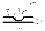
マイクロ流体デバイス内の流体の流れを選択的に制御するためのバルブが組み込まれたマイクロ流体デバイスが本明細書に記載されている。図1Aは一実施形態に係るマイクロ流体バルブ組立体1100の正面断面図を例示的に示す。マイクロ流体バルブ組立体1100は硬質基板1101および少なくとも1つのバルブ部材1107を備える。硬質基板1101は少なくとも2つの層1103および1104を含む。これらの層1103および1104は被検流体を移動させるための流体チャネル1106を画定している。バルブ部材1107は、伸縮性膜1108が流体チャネル1106から実質的に分離されるように層1103の上に位置する(任意にそこに固定された)伸縮性膜1108を含む。具体的には、図1Aに示すように、層1103は、層1103の内面と伸縮性膜1108の表面との間に所定の距離が存在するように伸縮性膜1108で覆われた任意の好適な形態の貫通穴または開口部を有していてもよい。
Microfluidic valve assembly A microfluidic device is described herein that incorporates a valve for selectively controlling the flow of fluid within the microfluidic device. FIG. 1A exemplarily shows a cross-sectional front view of a
硬質基板1101は、例えば、ポリメタクリル酸メチル(PMMA)、環式オレフィンコポリマー(COC)、環式オレフィンポリマー(COP)、他の硬質ポリマー、他の非ポリマー材料(例えば、金属、ガラス、シリコンなど)のうちの1種または組み合わせで作られている。伸縮性膜1108は、PDMS、ポリウレタン、ポリエステル、あらゆる他の軟質または伸縮性または弾性ポリマー、延伸ポリマー材料、軟質または伸縮性または弾性非ポリマーのうちの1種以上またはそれらの組み合わせで作られている。
The
バルブ部材1107は伸縮性膜1108に対する力の印加に基づき作動可能である。この力は、流体チャネル1106に存在する流体圧力と伸縮性膜1108の後ろの領域に存在する圧力との差により生成することができる。他の実施形態では、この力を、アクチュエーター、モーター、圧電素子、微小電気機械(MEMS)素子などによって生成することができる。図1Bはマイクロ流体バルブ組立体1100の正面断面図を例示的に示し、伸縮性膜1108に外部の力を印加して流体チャネル1106を閉鎖するための伸縮性膜1108の膨張を示す。外部の力はこの図では矢印によって示されている。
The
他の実施形態では、当該構造体は、バルブ部材に対向する層の部分が伸縮性膜に向かって突出してそこに接触して流体チャネル内に柱状部材を画定するように構成されていること以外は、図1Aに示すものと同じである。伸縮性膜は、流体チャネルと当該膜の外面との圧力差が負である場合に制御チャネルに向かって収縮して被検流体が流体チャネル内の柱状部材の上を流れるのを許可する。本明細書に定義されている「柱状」は、あらゆる形状または形状の組み合わせであってもよく、あるいは互いに分離された複数の構造体で構成されていてもよい。この構成においてPDMS膜は、通常は空気圧チャネルすなわち制御チャネルの真下にある流体チャネル内の柱状部材に接した状態で平らである。制御チャネル内の圧力が低い場合、被検流体の圧力は制御流体の圧力よりも高く、従って、被検流体の圧力はPDMS膜を押圧し、被検流体が柱状部材の上を流れて出口チャネルへと続くことができるようにPDMS膜を変形させて開放する。一実施形態では、バルブ部材の伸縮性膜は、流体チャネルに対向する膜の側面に対する圧力が流体チャネル内の圧力よりも大きい場合に流体チャネル内の被検流体の流れを閉鎖するために柱状部材の上に安定的に位置づけられている。言い換えると、当該膜の外側(流体チャネルに面している側と反対側)により多くの圧力を印加するとPDMS膜を平らな向きで位置づけることができ、柱状部材に接するようにPDMS膜を押圧して被検流体の流れを遮断する。これが「通常は閉鎖されている」バルブ構造体である。 In other embodiments, the structure is configured such that the portion of the layer facing the valve member protrudes toward and contacts the stretchable membrane to define a columnar member within the fluid channel. Is the same as shown in FIG. 1A. The stretchable membrane contracts toward the control channel when the pressure difference between the fluid channel and the outer surface of the membrane is negative, allowing the fluid under test to flow over the columnar member in the fluid channel. The “columnar shape” defined in the present specification may be any shape or combination of shapes, or may be composed of a plurality of structures separated from each other. In this configuration, the PDMS membrane is flat in contact with the columnar member in the fluid channel, usually directly below the pneumatic or control channel. When the pressure in the control channel is low, the pressure of the test fluid is higher than the pressure of the control fluid, so that the pressure of the test fluid presses the PDMS membrane and the test fluid flows over the columnar member and exits the channel. The PDMS film is deformed and released so that it can continue to In one embodiment, the stretchable membrane of the valve member is a columnar member for closing the flow of the fluid under test in the fluid channel when the pressure on the side of the membrane facing the fluid channel is greater than the pressure in the fluid channel. It is positioned stably on the top. In other words, when more pressure is applied to the outside of the membrane (opposite to the side facing the fluid channel), the PDMS membrane can be positioned in a flat orientation and pressed against the columnar member. To shut off the flow of the test fluid. This is the “normally closed” valve structure.
他の実施形態では、当該構造体は、柱状構造体が存在すること以外は図1Aに示すものと同じである。但し、この実施形態では、柱状部材は伸縮性膜とは接触しておらず、かつ伸縮性膜の下に位置している。伸縮性膜は、流体チャネル内の圧力と当該膜の外面(外部圧、当該膜の流体チャネルに向かう流体に面している側とは反対側)に対する圧力との差が正である場合に流体層の底から離れるように収縮して被検流体が流体チャネル内を流れるのを許可し、伸縮性膜は、流体チャネルと当該膜の外面との圧力差が負である場合に柱状部材の上面に向かって膨張して流体チャネル内の被検流体の流れを閉鎖するように構成されている。 In other embodiments, the structure is the same as that shown in FIG. 1A except that a columnar structure is present. However, in this embodiment, the columnar member is not in contact with the stretchable film and is located under the stretchable film. A stretchable membrane is fluid when the difference between the pressure in the fluid channel and the pressure on the outer surface of the membrane (external pressure, the opposite side of the membrane facing the fluid facing the fluid channel) is positive. The test membrane contracts away from the bottom of the layer to allow the test fluid to flow through the fluid channel, and the stretch membrane is the top surface of the columnar member when the pressure difference between the fluid channel and the outer surface of the membrane is negative. And is configured to close the flow of the test fluid in the fluid channel.
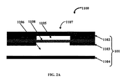
図2Aは、別の実施形態に係るマイクロ流体バルブ組立体1100の正面断面図を例示的に示す。図に示すように、マイクロ流体バルブ組立体1100は硬質基板1101および少なくとも1つのバルブ部材1107を備える。硬質基板1101は、第1の層1102、第2の層1103および第3の層1104などの複数の層を有する。第1の層1102および第2の層1103は制御チャネル1105を画定し、かつ第2の層1103および第3の層1104は流体チャネル1106を画定している。バルブ部材1107は、伸縮性膜1108が流体チャネル1106から実質的に分離されるように制御チャネル1105を密閉するように位置づけられた伸縮性膜1108を含む。硬質基板1101は、例えば、ポリメタクリル酸メチル(PMMA)、環式オレフィンコポリマー(COC)、環式オレフィンポリマー(COP)、他の硬質ポリマー、他の非ポリマー材料(例えば、金属、ガラス、シリコンなど)のうちの1種または組み合わせで作られている。伸縮性膜1108は、PDMS、ポリウレタン、ポリエステル、ポリエチレン(PE)、任意の他の軟質または伸縮性ポリマー、延伸ポリマー材料のうちの1種以上またはそれらの組み合わせで作られている。伸縮性膜1108は好適には伸縮性の非ポリマー材料であってもよい。
FIG. 2A exemplarily shows a cross-sectional front view of a
バルブ部材1107は流体チャネル1106と制御チャネル1105との圧力(例えば流体圧力)差に基づき作動可能である。一実施形態では、被検流体は流体チャネル1106を通って流れるように構成されており、制御流体は制御チャネル1105を通って流れるように構成されている。本明細書で使用される「被検流体」という用語は、実験室試験のために抽出された生体液試料(例えば血液)などのあらゆる流体試料を指し、流動固体、例えば限定されるものではないが砂状の粒子などの流動固体を含んでもよい。好ましい実施形態では、流体試料は生体液試料であり、より好ましくは血液である。血液試料を流体チャネル1106を通して流して、異なるチャネル領域内の特定の量の血液を検査する。本明細書で使用される「制御流体」という用語は、バルブ部材1107の伸縮性膜1108に圧力をかけて、例えば空気圧または油圧によりバルブ部材1107を駆動させるように構成されたあらゆる流体または液体、例えば、空気、ガス、油、砂などの流動固体を指す。
The
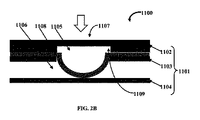
図2Bは、マイクロ流体バルブ組立体1100の正面断面図を例示的に示し、流体チャネル1106を閉鎖し、それにより被検流体の流れを遮断するための伸縮性膜1108の膨張を示す。一例では、バルブ部材1107またはバルブ点のための部分を画定するために1つ以上の貫通穴1109が第1の層1102および第2の層1103の中に作製されている。一実施形態では、バルブ部材1107の伸縮性膜1108は、流体チャネル1106と制御チャネル1105との圧力差が負である場合に図2Bにおいて矢印によって示されているように膨張し、第3の層1104に接触して流体チャネル1106における分析のための被検流体(例えば血液)または特定の化学反応のための試薬の流れを閉鎖する。バルブ部材1107が異なる断面を容易に有することができ、従って密閉がより容易になるので、この構成も有利である。
FIG. 2B exemplarily shows a front cross-sectional view of the
言い換えると、図2Bにおいて矢印によって示されているような制御流体の印加される圧力が被検流体の圧力よりも高ければ、バルブ部材1107の伸縮性膜1108は膨張して流体チャネル1106を閉鎖する。構成上、平らなPDMS層は上側PMMA層の上面に結合されているか単に適所に保持されている。空気圧層すなわち制御チャネル1105はPDMSの上に画定されている。複数のチャネルが第1および第2のPMMA層の中に切り込まれている。空気圧がPDMS層に印加されると、PDMS層は流体チャネル1106の中に伸長するように変形して被検流体の流れを遮断する。この構成が「通常は開放されている」バルブ構造体である。
In other words, the
本開示の様々な実施形態によれば、成形または他の技術によりPDMSを再成形して流体チャネル1106および制御チャネル1105ならびにマイクロ流体構造体の他の特徴部、例えばマイクロ流体力学的特徴部、すなわちチャネルおよびウェルなどを形成する代わりに、PDMS基板をPMMA、COCまたはCOPなどの硬質ポリマー基板の中に作製する。本開示の一実施形態によれば、硬質基板1101は、伸縮性膜1108すなわちPDMSが例えばその上にPDMS膜が位置しているPMMAの中間層の貫通穴を介して被検流体へのアクセスを有する特定の部分を有する。この設計は、空気圧がPDMSに印加されると、伸縮性膜1108がこの穴を通って下のチャネルの中に伸びて下のチャネル内の被検流体の流れを遮断するような設計である。
According to various embodiments of the present disclosure, PDMS can be reshaped by molding or other techniques to provide
従って、本実施形態では、本組立体は、1つの伸縮性膜1108と共に少なくとも1つの被検流体チャネル1106を含む。伸縮性膜1108はその中に設計された特徴部を有していても有していなくてもよい。本組立体の設計は、伸縮性膜1108が特定の点、例えばバルブ点においてのみ流体チャネル1106内で被検流体と接触するような設計である。さらに、空気圧または油圧により、あるいは機械力または電磁力などの他の方法によって伸縮性膜1108に対する圧力が増加または減少すると、伸縮性膜1108は、当該変形により流体チャネル1106が開閉されるように変形する。このように、本組立体全体が通常は開放されているか通常は閉鎖されているバルブ部材1107のいずれかとして機能する。圧力の変化を本組立体全体に加え、複数の「バルブ点」において伸縮性膜1108を同時に変形させ、かつ同時に流体ネットワーク全体の複数の位置において被検流体流の流れを増加させたり制限したりしてもよい。
Thus, in this embodiment, the assembly includes at least one
例示的な一実施形態では、バルブ部材1107は、伸縮性膜1108に印加される圧力により伸縮性膜1108を当該ネットワーク内の流体チャネル1106または他の構造体の中に変形させ、それにより当該ネットワーク内の指定された点において被検流体の経路を遮断または制限するように、特定の指定された点においてのみ流体ネットワーク内の被検流体と接触する可撓性膜または伸縮性膜1108の変形により作動される。あるいは、伸縮性膜1108は、被検流体の経路が開放されて流体の流れの増加を可能にするように変形する。
In one exemplary embodiment, the
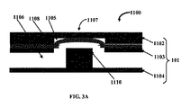
図3Aは、マイクロ流体バルブ組立体1100の一実施形態の正面断面図を例示的に示し、被検流体の流れを許可するための伸縮性膜1108の収縮を示しており、図3Bは、図3Aのマイクロ流体バルブ組立体1100の別の正面断面図を例示的に示し、伸縮性膜1108の通常の平らな向きを示している。一実施形態では、バルブ部材1107に対向する第3の層1104の部分は、伸縮性膜1108に向かって突出してそこに接触し、流体チャネル1106内に柱状部材1110を画定するように構成されている。伸縮性膜1108は、流体チャネル1106と制御チャネル1105との圧力差が正である場合に制御チャネル1105に向かって収縮して、被検流体が流体チャネル1106内の柱状部材1110の上を流れるのを許可する。本明細書に定義されている「柱状」はあらゆる形状または形状の組み合わせであってもよく、あるいは互いに分離された複数の構造体で構成されていてもよい。好ましくは、柱状構成は、その底面から突出しているあらゆる形状の1つ以上の構造体の組み合わせである。
FIG. 3A exemplarily shows a front cross-sectional view of one embodiment of the
構成上、PDMS膜は通常、空気圧チャネルすなわち制御チャネル1105の真下にある流体チャネル1106内で柱状部材1110に接した状態で平らである。制御チャネル1105内の圧力が低い場合、被検流体の圧力は制御流体の圧力よりも高く、従って、被検流体の圧力は、被検流体が柱状部材1110の上を流れて出口チャネルへと続くことができるように、PDMS膜を押圧し、PDMS膜を変形させて開放する。一実施形態では、バルブ部材1107の伸縮性膜1108は、流体チャネル1106と制御チャネル1105との圧力差が負である場合に流体チャネル1106内の被検流体の流れを閉鎖するために柱状部材1110の上に安定的に位置づけられている。言い換えると、制御チャネル1105内のより多くの圧力の印加によりPDMS膜を平らな向きに位置づけ、柱状部材1110に接するまでPDMS膜を押圧し、かつ被検流体の流れを遮断する。これが「通常は閉鎖されている」バルブ構造体である。
In construction, the PDMS membrane is generally flat in contact with the
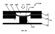
図4Aは、マイクロ流体バルブ組立体1100の別の実施形態の正面断面図を例示的に示し、高さが減少した柱状部材1110を示しており、図4Bは、図4Bのマイクロ流体バルブ組立体1100の別の正面断面図を例示的に示し、流体チャネル1106を閉鎖するための伸縮性膜1108の膨張を示している。一実施形態では、柱状部材110は伸縮性膜1108とは接触しておらず、伸縮性膜1108の下に位置している。伸縮性膜1108は、流体チャネル1106と制御チャネル1105との圧力差が正である場合に制御チャネル1105に向かって収縮して被検流体が流体チャネル1106内を流れるのを許可し、伸縮性膜1108は、流体チャネル1106と制御チャネル1105との圧力差が負である場合に柱状部材1110の上面1110aに向かって膨張して流体チャネル1106内の被検流体の流れを閉鎖するように構成されている。
FIG. 4A exemplarily shows a cross-sectional front view of another embodiment of a
構成上、この実施形態には、バルブ部材1107に伸縮性膜1108に接触しない柱状部材1110が組み込まれるように、図1A〜図1B、図2A〜図2Bおよび図3A〜図3Bに示す実施形態の態様が組み込まれている。従って、バルブ部材1107は制御チャネル1105内の圧力が低い場合より柔軟に開放し、被検流体が流れることができる。制御チャネル1105内の圧力が上昇すると、バルブ部材1107は閉じる。一例では、図2A〜図2Bに示すように、「通常は閉鎖されている」バルブ構造体の場合よりも制御チャネル1105内の圧力が低い場合に被検流体は柔軟に流れることができる。しかし、伸縮性膜1108と柱状部材1110の上面との間の空間が流体チャネル1106の通常の深さよりも小さいため、制御チャネル1105内の圧力を印加した場合に伸縮性膜1108を柱状部材1110に接した状態で密閉するのはより容易であり、故に、このバルブ部材1107を閉じるのも図2A〜図2Bに示す「通常は開放されている」構造体よりも非常に容易である。
In configuration, the embodiment shown in FIGS. 1A-1B, 2A-2B and 3A-3B is such that this embodiment incorporates a
一実施形態では、被検流体の経路の断面がより大きい場合に被検流体の流れに対する抵抗が少なくなり、かつ本組立体における背圧が少なくなり、従って、本組立体における流体流の生成または制御がより容易になるように、バルブ部材1107を除く当該構造体の大部分にわたってより深いチャネル深さが維持される。一例では、流体チャネル1106の幅を増加させることによって、より大きな断面を作り出すこともできるが、これはチップ上のx−y方向の空間を占め、これは、チップ上にチャネルの非常に長いネットワークが存在し得るため同じ流体背圧に対して当該チップをさらにより大きくする必要があることを意味している。例示的な実施形態では、制御チャネルおよび流体チャネルのそれぞれが、限定されるものではないが約50μm〜約1mmの幅および約5μm〜200μmの深さ(終点を包含する)を有する。他の例示的な実施形態では、制御チャネルおよび流体チャネルの寸法は、限定されるものではないがナノスケールまたはマイクロスケールであってもよい。
In one embodiment, the larger the cross-section of the path of the test fluid, the less the resistance to the flow of the test fluid and the less the back pressure in the assembly, and thus the generation of fluid flow in the assembly or A deeper channel depth is maintained over the majority of the structure except the
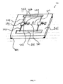
図5は、マイクロ流体バルブ組立体1100の別の実施形態の上面斜視図を示す破断図を例示的に示す。この実施形態では、第2の層1103は、流体チャネル1106と第2の層1103の上に位置するバルブ部材1107との連通を容易にし、かつ被検流体が実質的に流体チャネル1106の上を流れるのをさらに容易にするように構成された少なくとも2つの貫通孔1111aおよび1111bを含む。さらに、バルブ部材1107の断面積は流体チャネル1106の断面積とは異なる。貫通孔1111aは、被検流体を貫通孔1111aを通して第2の層1103の上に位置するPDMSバルブ部材1107まで移動させることができるように、第2の層1103に開けられた穴である。バルブ部材1107の上の外圧が被検流体の圧力および貫通孔1111bを通る流体チャネル1106内への背圧よりも小さい場合に被検流体が柱状部材1110の上を流れる。
FIG. 5 exemplarily shows a cutaway view showing a top perspective view of another embodiment of the
構成上、図5の実施形態は、図1A、図1B、図2A、図2B、図3A、図3B、図4Aおよび図4Bの実施形態の原理に従っている。図5に例示的に示されているように、この実施形態では、中間のPMMA層は、被検流体をその下の流体チャネル1106から中間のPMMA層の上側の中に作製されたバルブ部材1107に向かって移動させる貫通孔1111aを有し、次いで被検流体は別の貫通孔1111bを通して主要な流体チャネル1106に戻される。バルブ部材1107の深さは主要な流体チャネル1106よりも浅く、この実施形態では、バルブ部材1107の中央に柱状部材1110も存在する。PDMS層を中間のPMMA層の直接上にそれに接した状態で置く。上からのPDMS層への圧力の印加を増加させると下方への変形が生じ、バルブ部材1107すなわち「バルブチャネル」を遮断する。一実施形態では、バルブ部材1107の伸縮性膜1108には、バルブ部材1107が磁力によって駆動されるように構成されるように、磁気ビーズが埋め込まれている。他の実施形態では、バルブ部材は、静電気力または電磁力によって駆動されるように構成されている。
In configuration, the embodiment of FIG. 5 follows the principles of the embodiments of FIGS. 1A, 1B, 2A, 2B, 3A, 3B, 4A and 4B. As illustratively shown in FIG. 5, in this embodiment, the intermediate PMMA layer is a
一実施形態では、図4A〜図4Bおよび図5によれば、バルブ部材1107の構造は、バルブ部材1107における制御チャネル1105の深さが大きいこれらの種類の膜バルブを有効に密閉することは難しいため、バルブ部材1107における制御チャネル1105の深さが主要な流体チャネル1106内の被検流体の通常の深さには依存しないように設計されている。但し、流体チャネル1106の深さが一般に流体ネットワーク全体において浅ければ、流体チャネル1106の断面は所与のチャネル幅に対してより小さくなる。これは、被検流体の流れに対してより大きなインピーダンスが存在し、背圧がより大きく、そのため、被検流体が流体ネットワークを通して流れるのを許可するためにより多くの圧力が必要になることを意味している。従って、被検流体が漏出しないように流体ネットワークの有効な密閉が必要になるが、これは、より高い圧力およびチップ上での被検流体の高速の流れにおいてより難しい。故に、マイクロ流体バルブ組立体1100は、バルブ部材1107における制御チャネル1105の深さが一般的な流体チャネル1106の深さには依存しておらず、かつ流体ネットワークにおいてより低い流体圧力を維持しながらバルブ部材1107をより容易に閉鎖することができるように設計されている。故に、バルブ点における被検流体の流れは、流体ネットワークの残りの部分には依存しない異なる深さまたは層を有する経路を通る。
In one embodiment, according to FIGS. 4A-4B and 5, the structure of the
別の実施形態では、PDMSを硬質ポリマーの空洞内に流し込み、硬化させる。別の実施形態では、より複雑な流体経路および制御を可能にするためにPMMA層すなわち硬質層およびPDMS層すなわち空気圧層の複数の層を含む。一実施形態では、マイクロ流体バルブ組立体1100は、マイクロ流体チップおよび診断用途および他の用途のための他の構造体への応用が認められている。さらに、バルブ部材1107はマクロスケールおよびナノスケール用途に実装される。
In another embodiment, PDMS is cast into a rigid polymer cavity and allowed to cure. Another embodiment includes multiple layers of PMMA or hard layers and PDMS or pneumatic layers to allow more complex fluid pathways and control. In one embodiment, the
マイクロ流体センシングプラットフォーム
本明細書に記載されている技術は、1種以上の標的因子の存在を検出および/または定量化するシステムおよび方法にも関する。特に、限定されるものではないが、本開示の有用性の一例は、複数のタンパク質バイオマーカー疾患検査のためであり、これを標準的なプロセスを用いて手作業での実験室ベースのタンパク質アッセイからポイントオブケアで患者を検査するために使用することができる卓上型、ベンチトップ型または手持ち式の集積化および自動化アッセイに変換することができる。本開示のより詳細な理解を与え、かつ実験室ベースの標的因子定量化試験を集積化された卓上またはベンチトップ型に変換するその応用方法を示すために、本開示の特定の実施形態について以下に説明する。
Microfluidic sensing platform The techniques described herein also relate to systems and methods for detecting and / or quantifying the presence of one or more target agents. In particular, but not by way of limitation, an example of the utility of the present disclosure is for testing multiple protein biomarker diseases, which can be performed manually using a standard process and a laboratory-based protein assay. Can be converted to a tabletop, benchtop or hand-held integrated and automated assay that can be used to examine the patient from point of care. In order to provide a more detailed understanding of the present disclosure and to show how it can be applied to convert laboratory-based target factor quantification tests to an integrated tabletop or benchtop format, specific embodiments of the present disclosure are described below. Explained.
一定義では、集積化システムは、正確な動作のために必要な全ての要素を備える好都合な場合によりモジュール式のパッケージである。一定義では、自動化システムは、被検試料の最適な分析のためにオペレーターとの最小の対話を必要とするか対話を必要としない複数の動作上相互依存的な部品(相当な物理的距離だけ分離させることができる)を含むシステムである。 In one definition, an integrated system is a convenient, more modular package that includes all the necessary elements for correct operation. In one definition, an automated system requires multiple, interdependent parts (only a substantial physical distance) that require minimal or no interaction with the operator for optimal analysis of the specimen. System that can be separated).
図6は、マイクロ流体チップ100の単純な全体像を具体化したものである。この実施形態では、マイクロ流体チップ100はmm範囲の全横方向寸法を有する。これは手持ち式検査にとって特に有用である。いくつかの他の実施形態では、マイクロ流体チップ100は、mm範囲ではなく、例えばcm範囲の横方向寸法を有していてもよい。図示されているマイクロ流体チップ100は、複数の材料および/または複数の材料の組み合わせから複数の方法で構築することができる。例えば、マイクロ流体チップ100は半導体、セラミックス、金属およびポリマーなどの固体材料から構築することができる。これをサブトラクティブ法によって構築することができ、材料の塊から開始し、湿式または乾式の化学的または機械的方法を用いて材料を除去して当該材料を含まないチャネル、ウェルおよび他の構造体を形成する。これをアディティブ法によって構築することもでき、基板上への接着、蒸着、スパッタリング、化学蒸着(CVD)または他の種類の成膜を用いて1種または複数種の材料からなる1つまたはいくつかの層を基板109に追加してマイクロ流体チップ100構造体を形成する。あるいは、チップ材料を折り曲げるか成形するか他の方法で形状を変化させる形成方法を用いて、これを構築することができる。物理的力または加熱/冷却または他の力を使用してこれを達成してもよい。また、経時的および/または別の材料に混合/曝露した場合にそれらの物理的構造を変化させる性質を有するいくつかの材料を使用してこれを達成してもよい。この一例はエポキシ樹脂であり、これは特定のエポキシ硬化剤に混合すると硬化する。モールドを使用してもよく、この成形プロセスを達成するために、当該材料を液状に変換させた後に放冷してもよい。次いで、このモールドを複数の方法でマイクロ流体チップ100から物理的に分離することができる。いくつかの方法はモールドおよびマイクロ流体チップ100の両方の形状を保つ。一例は剥離法である。いくつかの他の方法は、マイクロ流体チップ100の形状を保つがモールドの形状は保たない。一例はモールドを化学溶液の中に浸漬してそれを溶解する方法である。最初の方法は多くのチップを作製するためにモールド何回も利用し、それにより作製コストを減少させることができるため、通常は好ましい。これらの方法および他の方法の組み合わせを使用してマイクロ流体チップ100を構築してもよい。図6に示されているマイクロ流体チップ100を構築するために用いられる一般的な方法のいくつかの例としては、(1)シリコンまたは他の半導体(または他の材料)からなる硬質基板に対するリソグラフィーが挙げられ、ここでは、スピニングまたは他の方法により特定のポリマーを当該材料の上に追加し、その後に特別に設計されたマスクを介して公知の強度および波長の光または他の放射線の曝露を行う。次いで、曝露されたポリマーを除去し(あるいは代わりとして曝露されていないポリマーを除去し)、次いでスパッタリングまたは蒸着または他のアディティブ法を使用して材料を基板上に成膜するか、エッチング法を使用してポリマーが存在しない基板材料を除去する。その後、残っているポリマーを除去し、ポリマーが存在しないさらなる部分(または除去された材料)のみを残す。連続リソグラフィーおよびアディティブ/サブトラクティブ工程を使用してマイクロ流体チップ100構造体を構築するこができる。(2)マイクロ流体チップ100基板がポリマーである場合、これを加熱してポリマーを柔らかくし、次いで硬質材料で構築されたモールドに圧入し、必要なチップ設計になるようにポリマーを放冷して硬化させる。次いで、このモールドを取り外す。(3)マイクロ流体チップ100基板は、経時的および/または異なる材料に曝露された場合および/または温度が変化した場合にその物理的構造を変化させる材料で作ることができる。この材料は最初に流体形態であってもよく、次いで硬質または軟質または可撓性材料で構築されたモールドに流し込み、この流体を異なる材料に曝露することによって、および/または温度の変化によって硬化させる。次いで、このモールドを取り外す。必要に応じて、マイクロ流体チップ100を構築するために利用される材料を流体形態のまま液体および粉末形態の任意の他の材料と混合して得られるチップ材料の物理的特性を変化させることができる。(4)マイクロ流体チップ100基板を、他の機械的および光学的方法によって、例えば高強度レーザーをポリマー、金属、ガラス、シリコン、セラミック、複合材または他の材料で作られた基板に照射するレーザーマイクロマシニング(基板を極めて高い解像度を有する必要な形状に機械加工することができる)を用いて直接成形することができる。この方法または同様の方法を使用して(2)および(3)のために好適なモールドを機械加工することもできる。
FIG. 6 embodies a simple overview of the
マイクロ流体チップ100の上記構築方法の多くは、同じまたは同様のパターンをマイクロ流体チップ100全体にわたって繰り返すことができ、全てのそのような構造体を1組のチップ構造体の構築を可能にするのに必要な同じ(またはほぼ同じ)数の工程を通して作製することができるバッチ構築方法である。これにより、複数の標的因子の定量化のために複雑な構造体を含むマイクロ流体チップ100の製造が可能になり、かつそのようなマイクロ流体チップ100の製造を1種類の標的因子のみの定量化のために1組の構造体を含むマイクロ流体チップ100の製造の複雑性と同程度にすることができる。
Many of the above construction methods of the
マイクロ流体チップ100の他の実施形態は、マイクロ流体チップ100上に異なるチップ形状および部品のレイアウトを有し、かつこの特定の実施形態と正確または同様に機能することができる。この特定の実施形態では、デバイス内のマイクロ流体チップの適切な機能を有するために、本デバイス内に置いた場合にそれを正確に位置合わせするのを支援するために、マイクロ流体チップ100上に磁気点101が存在する。但し、マイクロ流体チップ100の他の実施形態は、代わりに位置合わせのクリップ、スロットもしくは他の機械的方法、位置合わせの静電法もしくは電磁法、または機能性に影響を与えることのない標準的デバイスにおいて先に詳述した任意の他の形態の位置合わせ機構を含んでもよく、これらは全て本開示の実施形態である。
Other embodiments of the
各種チャネルおよびウェルを含むマイクロ流体チップ100の異なる構造体を各種材料でコーティングすることもできる。コーティングは、マイクロ流体チップ100の構築中の蒸着またはスパッタリングあるいは他のアディティブ法によるものであってもよい。あるいは、1種以上の流体をチャネルまたはウェルに通してコーティングを被覆してもよい。このコーティングは異なる機能を行ってもよく、例えば、各種チップ構造体の中または隣を通り抜ける標的因子、埃または流体中の他の構造体がこれらのチップ構造体の各種表面に付着するのを防止するために疎水性または帯電性であってもよい。あるいは、マイクロ流体チップ100構造体の表面は、特定の標的因子がそれらに付着するように親水性であってもよい。異なるチップ構造体または構造体の一部は、チップ機能のために必要に応じて疎水性、親水性、帯電性であるか他の特性を有するように構築またはコーティングされていてもよい。
Different structures of the
マイクロ流体チップ100は、少なくとも1種の標的因子を含む流体および任意の試薬ならびに本開示が少なくとも1種の標的因子を定量化するその機能を達成するために添加が必要な他の流体を導くための各種チャネルを有する。少なくとも1種の標的因子を含む1種以上の流体を連続的な流れとして輸送してもよく、担体流体を含まないマイクロ液滴として輸送してもよく、あるいはチップを通る1種以上の流体のあらゆる他の輸送方法が存在してもよい。「マイクロ流体」とは、流体が輸送されるチップ上の構造体の寸法が通常は1mm未満であることのみを意味し、この呼称はどんな特定の流体輸送方法を指すものではない。102は入力チャネルを示す。入力チャネル102は様々な形状であってもよく、この実施形態で図示されている寸法はマイクロメーター範囲であるが、他の実施形態では、これらはナノメートル範囲であってもよく、あるいはチップの形式および寸法と連続するようにそれよりも大きくても小さくてもよい。さらに、チップに対する入力チャネル102の方向および経路も機能に影響与えない多くの他の形状であってもよい。入力チャネル102は定量化される少なくとも1種の標的因子を含む少なくとも1種の流体のための入口点である。流体の一例は清浄度を決定するために1種以上の標的因子について検査される貯蔵所からの水であってもよい。あるいは、当該流体は、例えば血中の各種標的因子、例えばタンパク質バイオマーカーについて検査される患者の血液由来の血清であってもよい。当該流体は各種方法、例えば入力チャネル102に供給するウェルにより入力チャネル102に入れてもよく、このウェルの中には入力チャネル102の前方に取り付けられた血液を直接採取するために患者の皮膚に穿刺する注射器または「針穿刺」装置から流体を入れることができる。そのような場合の血液は入力チャネルに直接入れるか、全血から得られた血清、血漿または他の成分が入力チャネルに入れられるように、濾過または他の方法で処理する。なお、入力チャネル102に入れられる流体の量を定量化するという要求は必ずしも存在するわけではない。
The
103は出力チャネルを示す。出力チャネル103は様々な形状であってもよく、この実施形態で図示されている寸法はマイクロメーター範囲であるが、他の実施形態では、これらはチップの形式および寸法と連続するようにそれよりも大きくても小さくてもよい。
さらに、チップに対する出力チャネル103の方向および経路も機能に影響与えない多くの他の形状であってもよい。出力チャネル103は、流体を出力チャネル103から流出させる方法(例えば疎水性コーティング)により構築または被覆することができ、あるいは、動作のために必要な場合に静電気力または帯電力または機械力などの特定の場または力を使用して流体を能動的に流出させることができる。必要な場合に、同様の方法および出力チャネル103の物理的遮断も用いて出力チャネル103からの流体の流出を防止することができる。
Furthermore, the direction and path of the
104は捕捉ウェルを示す。マイクロ流体チップ100は、各種寸法および形状で具体化することができる少なくとも1つの捕捉ウェル104を含む。その構造体は小さいチャンバー構造である。あらゆる他のコーティングに加えて、この特定の構造体は、捕捉ウェル104の構築中に捕捉ウェル104の中に置かれる少なくとも1種の捕捉剤を含む。滴下コーティングなどの手作業による方法で捕捉剤を捕捉ウェル104の中に置いてもよい。あるいは、先端を流体の中に浸すか流体を先端の上に流し、次いでこの先端を当該表面に当てる方法を用いて捕捉剤を捕捉ウェル104の表面にコーティングしてもよく、インクジェット印刷法もしくはインクジェット法と同様の方法または捕捉剤を当該表面の上に噴霧する他の方法を用いてそれを当該表面の上に印刷してもよく、あるいは捕捉剤を当該技術分野において記載されている多くの他の一般に公知の方法で塗布してもよい。捕捉剤を固体の形態で塗布してもよく、あるいは流体またはエアロゾルに運ばせて塗布してもよい。後者の場合、それを乾燥させて捕捉ウェル104内にスポットまたは層を形成してもよい。
104 indicates a capture well. The
この実施形態では、捕捉ウェル104は1つのみの入力チャネル102から供給される。他の可能な実施形態では、捕捉ウェル104は2つ以上の入力チャネル102から供給されてもよい。各入力チャネル102は少なくとも1種の流体の入口点である。一実施形態では、いくつかの流体を1つのみの入力チャネル102から捕捉ウェル104に入れてもよい。別の実施形態では、いくつかの流体を2つ以上の入力チャネル102から捕捉ウェル104に入れてもよい。別の実施形態では、いくつかの流体を1つのみの入力チャネル102から捕捉ウェル104に入れてもよい。 In this embodiment, capture well 104 is provided from only one input channel 102. In other possible embodiments, the capture well 104 may be supplied from more than one input channel 102. Each input channel 102 is an entry point for at least one fluid. In one embodiment, some fluid may enter the capture well 104 from only one input channel 102. In another embodiment, some fluid may enter the capture well 104 from more than one input channel 102. In another embodiment, some fluid may enter the capture well 104 from only one input channel 102.
この実施形態では、捕捉ウェル104は1つのみの出力チャネル103を有する。他の可能な実施形態では、捕捉ウェル104は2つ以上の出力チャネル103に供給してもよい。各出力チャネル103は少なくとも1種の過剰流体または廃棄流体の出口点である。一実施形態では、いくつかの流体を1つのみの出力チャネル103を通して捕捉ウェル104から排出してもよい。別の実施形態では、いくつかの流体を2つ以上の出力チャネル103を通して捕捉ウェル104から排出してもよい。別の実施形態では、いくつかの流体を1つのみの出力チャネル103を通して捕捉ウェル104から排出してもよい。
In this embodiment, capture well 104 has only one
これらの実施形態では、全ての実施形態ではないが、捕捉ウェル104と検出ウェル108との間に接続チャネル105が存在する。他の実施形態では、0個、1個または多くのこれらの接続チャネル108が存在してもよい。一般に、流体がなおマイクロ流体チップ100の内外に流れることができ、かつ検出剤および捕捉剤に正しい順序で曝露される限り、ここに具体化されている設計に対してチップへ/からのチャネルの追加/削除があってもよい。
In these embodiments, a
マイクロ流体チップ100は、各種寸法および形状で具体化することができる少なくとも1つの検出ウェル108を含む。その構造体は小さいチャンバー構造である。
The
あらゆる他のコーティングに加えて、この特定の構造体は検出ウェル108の構築中に検出ウェル108内に置かれる少なくとも1種の検出剤を含む。滴下コーティングなどの手作業による方法で検出剤をウェルの中に置いてもよい。あるいは、先端を流体の中に浸すか流体を先端の上に流し、次いでこの先端を当該表面に当てる方法を用いて検出剤を検出ウェル108の表面にコーティングしてもよく、インクジェット印刷法もしくはインクジェット法と同様の方法または検出剤を当該表面の上に噴霧する他の方法を用いてそれを当該表面の上に印刷してもよく、あるいは検出剤を当該技術分野において記載されている多くの他の一般に公知の方法で塗布してもよい。検出剤を固体の形態で塗布してもよく、あるいは流体またはエアロゾルに運ばせて塗布してもよい。後者の場合、それを乾燥させて検出ウェル108内にスポットまたは層を形成してもよい。
In addition to any other coatings, this particular structure includes at least one detection agent that is placed in the detection well 108 during construction of the
この実施形態では、検出ウェル108はどの入力チャネル102からも供給されない。他の可能な実施形態では、検出ウェル108は1つの入力チャネル102から供給されてもよい。他の可能な実施形態では、検出ウェル108は2つ以上の入力チャネル102から供給されてもよい。各入力チャネル102は少なくとも1種の流体の入口点である。一実施形態では、いくつかの流体を1つのみの入力チャネル102を通して検出ウェル108に入れてもよい。別の実施形態では、いくつかの流体を2つ以上の入力チャネル102を通して検出ウェル108に入れてもよい。別の実施形態では、いくつかの流体を1つのみの入力チャネル102を通して検出ウェル108に入れてもよい。 In this embodiment, the detection well 108 is not supplied from any input channel 102. In other possible embodiments, the detection well 108 may be supplied from one input channel 102. In other possible embodiments, the detection well 108 may be supplied from more than one input channel 102. Each input channel 102 is an entry point for at least one fluid. In one embodiment, some fluid may enter the detection well 108 through only one input channel 102. In another embodiment, some fluid may enter the detection well 108 through more than one input channel 102. In another embodiment, some fluid may enter the detection well 108 through only one input channel 102.
この実施形態では、検出ウェル108は0個の出力チャネル103を有する。他の可能な実施形態では、検出ウェル108は1つの出力チャネルに供給してもよい。他の可能な実施形態では、検出ウェル108は2つ以上の出力チャネル103に供給してもよい。各出力チャネル103は少なくとも1種の過剰流体または廃棄流体の出口点である。一実施形態では、いくつかの流体を1つのみの出力チャネルを通して検出ウェル108から排出してもよい。別の実施形態では、いくつかの流体を2つ以上の出力チャネル103を通して検出ウェル108から排出してもよい。別の実施形態では、いくつかの流体を1つのみの出力チャネル103を通して検出ウェル108から排出してもよい。
In this embodiment, the detection well 108 has zero
107は遮断手段を示す。遮断手段107は様々な形状であってもよく、この実施形態で図示されている寸法はマイクロメーター範囲であるが、他の実施形態では、これらはチャネル形状および寸法と連続するようにそれよりも大きくても小さくてもよい。遮断手段107の目的は、捕捉ウェル104と検出ウェル108との間に置いた際に、これらの2つのウェルの間の流体の通過を阻害することである。これらの2つのウェルの間からこれを除去すると流体はこれらの2つのウェルの間を通過することができる。この実施形態では、遮断手段107は物理的物体である。これを異なる形状で構築することができるが、この実施形態では立方形の形状である。遮断手段107をあらゆる材料から構築することもできる。この実施形態では、遮断手段はニッケルなどの磁性金属から構築されている。遮断手段107は、その機能をより良好に行わせることができるように、各種コーティングまたは複数のコーティングでコーティングされていてもコーティングされていなくてもよい。この実施形態では、遮断手段107は金属イオンがチップを通って流れるあらゆる流体の中に浸出するのを防止し、かつ遮断手段が移動した際のチャネルまたはウェルへの摩擦および損傷も減少させるポリマーでコーティングされている。また、当該ポリマーは、遮断手段がその機能をより良好に行うように、あらゆる流体が遮断手段の周りを通過するのを阻害するように疎水性であってもよい。物体を移動させるために肉眼的、顕微鏡的またはそれよりも小さいスケールで利用される機械力、磁力、静電気力またはあらゆる他の力を用いて、遮断手段107を移動させることができる。この実施形態では、電磁気により生成される磁力を用いて遮断手段107を移動させる。遮断手段107を受動的または能動的に制御することができる。この実施形態では、電磁気および従って遮断手段107の移動を能動的に制御する。あるいは、この実施形態で図示されている移動する遮断手段107に、流体の流れを遮断するための各種他の方法、例えばバルブまたはゲートを用いることができる。あるいは、遮断手段107は非物理的、例えば静電気力または疎水性もしくは親水性力を使用して流体の流れを必要に応じて防止または許可することができる。流体の流れを遮断する公知のあらゆる他の方法を用いることができる。
この実施形態では、遮断手段107は、捕捉ウェル104と検出ウェル108との間の接続チャネル105に垂直かつ交差している遮断チャネル106内に含まれている。これにより、遮断手段107を必要な場合に遮断チャネル106と接続チャネル105との接合部に移動させて捕捉ウェル104と検出ウェル108との間の流体の流れを遮断し、かつ必要な場合に遮断チャネル106内の異なる位置に移動させて接続チャネル105を遮断せずに流体の流れを許可することができる。いくつかの実施形態では、入力チャネル102と捕捉ウェル104との間にも遮断手段107が存在するか、捕捉ウェル104と出力チャネル103との間に遮断手段107が存在するか、あるいはマイクロ流体チップ100上の他の点またはこの実施形態で図示されていない構造体の間に遮断手段107が存在してもよい。遮断手段107は同じまたは異なる原理で作動してもよい。全ての実施形態における遮断手段107はチップ全体における流体の流れの制御を可能にし、かつ従って、少なくとも1種の標的因子を含む流体の各捕捉剤または各検出剤への曝露が制御されるため、検出剤および捕捉剤の制御を可能にする。特定の実施形態では、遮断手段107は、特定の制御された期間にわたって特定のウェルまたは他のチップ構造体内への小分けした流体を遮断することができるため、特定の捕捉剤または特定の検出剤に曝露される少なくとも1種の標的因子を含む流体の量を制御することも可能にする。同様に、遮断手段は制御された期間にわたって特定のウェルまたは他のチップ構造体内への他の試薬を含む他の流体を遮断することができる。
In this embodiment, the blocking means 107 is included in a blocking
他の実施形態では、検出剤を捕捉チャンバー内に噴霧することができ、あるいは固体の形態であるか液体または他の媒介物に入れて運ばれる各薬剤をマイクロ流体チップ100の周りに個々に移動させるか移動するように制御することができる。これらおよび他の例はそれぞれ、少なくとも1種の標的因子を含む流体の各少なくとも1種の捕捉剤および各少なくとも1種の検出剤への曝露が個々に制御される本開示の原理の実施形態である。
In other embodiments, the detection agent can be sprayed into the capture chamber, or each agent that is carried in solid form or contained in a liquid or other vehicle is individually moved around the
この実施形態では少なくとも1種の標的因子を含む流体は入力チャネル101の中に流れ、そこから捕捉ウェル104の中に流れる。捕捉ウェル104では、少なくとも1種の捕捉剤は少なくとも1種の標的因子を捕捉する。この実施形態では、捕捉ウェル104は、どの捕捉剤がどの標的因子を捕捉した場合であっても、どの捕捉剤も捕捉ウェル104の表面に付着したままであるように構築されている。さらに、捕捉剤を含んでいない捕捉ウェル104のあらゆる部分は、捕捉ウェル104を通って流れる標的因子またはあらゆる他の材料が捕捉ウェル104の表面に付着するのを防止するように構築されている。この第1の工程では、遮断手段は接続チャネル105を遮断し、流体が検出チャンバーの中に流れるのを防止する。第2の工程では、生物学的プロセスで使用される標準的な洗浄流体を捕捉ウェル104に通して洗浄して少なくとも1種の標的因子を含む流体およびあらゆる未結合の標的因子を洗い流す。第3の工程では、遮断手段107を接続チャネル105から遮断チャネル106の異なる部分の中に除去する。従って、流体は検出ウェル108の中に流れる。これによりこのウェル内の少なくとも1種の検出剤が当該流体と混ざり、次いで検出剤が捕捉ウェル104の中に移動し、捕捉ウェル104において少なくとも1種の捕捉剤に結合された少なくとも1種の標的因子と反応する。特定の実施形態では、捕捉ウェル104または他の点への入口または出口に他の遮断部材が存在する場合にも、これらを使用して確実に検出剤を選択された時間にわたって特定の濃度で捕捉ウェル104内の捕捉された標的因子に曝露させることができる。第4の工程では、洗浄流体を流してあらゆる未結合の検出剤を洗い流す。第5の工程では、少なくとも1種の捕捉された標的因子の存在を決定するか、あるいは代わりとして少なくとも1種の捕捉された標的因子の存在を決定し、かつ捕捉された少なくとも1種の標的因子の量を定量化する(以下を参照)。
In this embodiment, fluid containing at least one target agent flows into the
他の実施形態では、上記第4の工程と第5の工程との間に、少なくとも1種の試薬を含むさらなる流体がマイクロ流体チップ100を通って流れ、この試薬が捕捉剤、標的因子または検出剤あるいは本明細書に記載されている開示の動作に関与する別の試薬と結合するかそれ以外の方法で反応する中間の工程が存在する。次いで、さらなる洗浄工程を行って、あらゆる未結合の成分またはそれ以外に未反応もしくは不必要な成分を除去する。さらなる他の実施形態では、試薬をマイクロ流体チップ100を通して流す複数の工程および/または複数の洗浄工程が存在してもよい。
In other embodiments, additional fluid comprising at least one reagent flows through the
さらなる他の実施形態では、少なくとも1種の他の試薬はマイクロ流体チップ100の上を流れる代わりに、マイクロ流体チップ100の別の部分の中に含まれる。別の実施形態では、当該試薬はマイクロ流体チップ100の別の部分に含まれ、かつ遮断手段107が除去されるまでそれが捕捉剤、標的因子または検出剤と反応するのを防止する遮断手段107が存在する。この場合も他の実施形態では、マイクロ流体チップ100上に複数の試薬が存在してもよい。
In still other embodiments, at least one other reagent is included in another portion of the
他の実施形態では、これらの工程を異なる順序で行い、同様にマイクロ流体チップ100上に存在するか、必要に応じてマイクロ流体チップ100の上および中を流れるさらなる試薬によるさらなる工程またはより少ない工程または異なる工程が存在してもよい。例えば、別の実施形態では、検出剤を少なくとも1種の標的因子を含む流体と混合してもよい。他の実施形態では、試薬を混合してもよい。
In other embodiments, these steps are performed in a different order, with additional or fewer steps with additional reagents that are also present on the
各種他の実施形態では、これらの実施形態において設計されている形状、寸法およびマイクロ流体チップ100の各種部品間の接続は異なる。さらなる試薬も必要となる場合があり、これをマイクロ流体チップ100上に含めるかマイクロ流体チップ100の上に流してもよく、あるいはこれらの組み合わせが存在してもよい。
In various other embodiments, the shapes, dimensions, and connections between the various components of the
いくつかの実施形態では、マイクロ流体チップ100は、結合された標的因子のための定量化システムの一部をなすためのセンシング構造体も含む。これらのセンシング構造体は、捕捉ウェル104の中または捕捉ウェル104の真下および/または上に位置していることが好ましいが必ずしもそうではない。これにより、さらなる処理を必要とすることなく標的因子が捕捉された際にその即座の定量化が可能となる。そのようなセンシング構造体の実施形態としては以下が挙げられる(但し、それらに限定されない)。
In some embodiments, the
(1)振動が生じるチップ上の構造体である振動センサー。当該構造体の振動数は質量によって決まるため、振動センサーに付着するあらゆる材料の量に従って変化し、かつこの振動の変化は標的因子の濃度に関連している。これらのセンサーの例としては、小型水晶振動子マイクロバランス(QCM)および弾性表面波(SAW)構造体が挙げられる。 (1) A vibration sensor that is a structure on a chip that generates vibration. Since the frequency of the structure is determined by mass, it varies with the amount of any material attached to the vibration sensor, and this change in vibration is related to the concentration of the target factor. Examples of these sensors include small quartz crystal microbalance (QCM) and surface acoustic wave (SAW) structures.
(2)流体中の薬剤との反応により標的因子濃度に関連する電気信号が発生する電気化学センサー。典型的な電気化学センサーは、絶縁材の薄層によって分離された検知電極および対電極からなる。これらのセンサーの例としては、電位差測定バイオセンサーが挙げられる。 (2) An electrochemical sensor that generates an electrical signal related to a target factor concentration by reaction with a drug in a fluid. A typical electrochemical sensor consists of a sensing electrode and a counter electrode separated by a thin layer of insulating material. Examples of these sensors include potentiometric biosensors.
(3)薬剤とセンサーのいくつかの部品との相互作用によりセンサーのこれらの部分の電気特性の変化が生じ、これらの特性の変化が標的因子濃度に関連している電子センサー。これらのセンサーの例としては電界効果トランジスタ(FET)が挙げられ、ここでは薬剤がFETのゲートに結合することによりFETのソースとドレインとの間の抵抗性が変化する。 (3) An electronic sensor in which the electrical properties of these parts of the sensor change due to the interaction of the drug with some parts of the sensor, and the change in these properties is related to the target factor concentration. Examples of these sensors include field effect transistors (FETs), where the drug binds to the gate of the FET to change the resistance between the source and drain of the FET.
(4)磁場に対する応答においてそれらの出力電圧を変える変換器であるホール効果センサー。出力電圧変動は標的因子濃度に関連している。 (4) Hall effect sensors that are converters that change their output voltage in response to a magnetic field. The output voltage variation is related to the target factor concentration.
(5)標的因子の濃度に関連する光の吸収または放射が生じる光センサー。この光の吸収は、例えば分光測色法によって測定することができる、例えば薬剤と酵素などの他の試薬との化学反応による基板における色の変化に起因していても、薬剤の光学的特性による1種以上の特定の波長の光の直接吸収または放射に起因していても、あるいは蛍光または発光構造体が付着している薬剤に起因していてもよい。これらのセンサーの例としては、酵素免疫測定法(ELISA)および光ルミネッセンスセンサーが挙げられる。 (5) An optical sensor that generates light absorption or emission related to the concentration of the target agent. This light absorption can be measured, for example, by spectrocolorimetry, for example, due to the optical properties of the drug, even though it is due to a color change in the substrate due to a chemical reaction between the drug and another reagent such as an enzyme. It may be due to direct absorption or emission of one or more specific wavelengths of light, or may be due to a drug to which a fluorescent or luminescent structure is attached. Examples of these sensors include enzyme immunoassay (ELISA) and photoluminescence sensors.
(6)光信号の変動が標的因子の濃度に関連している他の光検出法を用いる光センサー。そのような光検出システムの例としては、干渉分光法または近接場光学顕微鏡法(エバネッセント波の変動の測定)が挙げられる。 (6) Photosensors using other photodetection methods where the variation of the optical signal is related to the concentration of the target factor. Examples of such a light detection system include interferometry or near-field optical microscopy (measurement of evanescent wave variation).
(7)薬剤の付着によって導入されるさらなる応力によりセンサーの物理的形状の変形が引き起こされる機械センサー。標的因子濃度に関連しているこの変形は、例えば光干渉法あるいは材料の電気的、機械的、磁気的または構造的特性の変化によって検出することができる。これらのセンサーの例としては、カンチレバーセンサーおよび圧電センサーが挙げられる。 (7) A mechanical sensor that causes deformation of the physical shape of the sensor due to additional stress introduced by the attachment of the drug. This deformation associated with the target factor concentration can be detected, for example, by optical interferometry or a change in the electrical, mechanical, magnetic or structural properties of the material. Examples of these sensors include cantilever sensors and piezoelectric sensors.
完全性のために、標的因子を含む流体のいくつかの例としては、(1)定量化される特定の無機化学物質を含む商業用途または非商業用途、例えば化学工業のために使用されるあらゆる溶液または懸濁液、(2)特定の有機化学物質を含む商業用途または非商業用途のために使用されるあらゆる溶液または懸濁液、(3)あらゆる生体液、(4)ヒトまたは動物から得られるあらゆる流体、特に血液、尿、粘液、唾液および脳脊髄液(5)植物、真菌、細菌または古細菌などの他の生物有機体から得られるあらゆる流体、(6)あらゆる他の生物学的実体から得られるあらゆる流体、(7)食品産業で生じる生成物を含む流体、および(8)河川、海、雨、下水処理場または他の供給源からの水が挙げられる。 For completeness, some examples of fluids containing the target agent include (1) any commercial or non-commercial application involving the particular inorganic chemical being quantified, such as those used for the chemical industry Solutions or suspensions, (2) any solution or suspension used for commercial or non-commercial applications involving specific organic chemicals, (3) any biological fluid, (4) obtained from humans or animals Any fluids, especially blood, urine, mucus, saliva and cerebrospinal fluid (5) any fluid obtained from other biological organisms such as plants, fungi, bacteria or archaea, (6) any other biological entity (7) fluids containing products produced in the food industry, and (8) water from rivers, seas, rain, sewage treatment plants or other sources.
完全性のために、標的因子のいくつかの例としては、(1)抗体、抗原、酵素および他のタンパク質またはタンパク質を含む構造体などのタンパク質(天然および合成の両方)、(2)ペプチド(天然および合成の両方)、(3)アミノ酸またはアミノ酸を含む構造体(天然および合成の両方)、(4)DNA(天然および合成の両方)、(5)RNA(天然および合成の両方)、(6)核酸または核酸を含む構造体(天然および合成の両方)、(7)糖類または糖類を含む構造体(天然および合成の両方)、(8)脂質または脂質を含む構造体(天然および合成の両方)、(9)他の生体分子および生体分子を含む構造体(天然および合成の両方)、(10)全細胞または細胞の一部または細胞群(非細胞構造体を包含しても包含しなくてもよい)、(11)細胞を含むあらゆる構造体、(12)あらゆる他の生物学的構造体、および(13)捕捉剤によって認識することができ、かつ標的因子に結合して固定化するために使用することができる具体的なパターンを有するあらゆる非生物学的化学構造体が挙げられる。 For completeness, some examples of target factors include (1) proteins (both natural and synthetic) such as antibodies, antigens, enzymes and other proteins or structures containing proteins, (2) peptides ( (Both natural and synthetic), (3) amino acids or structures containing amino acids (both natural and synthetic), (4) DNA (both natural and synthetic), (5) RNA (both natural and synthetic), ( 6) Nucleic acids or structures containing nucleic acids (both natural and synthetic), (7) saccharides or structures containing saccharides (both natural and synthetic), (8) lipids or structures containing lipids (natural and synthetic) Both), (9) other biomolecules and structures containing biomolecules (both natural and synthetic), (10) whole cells or parts of cells or groups of cells (including non-cellular structures) Without Good), (11) any structure containing cells, (12) any other biological structure, and (13) can be recognized by the capture agent and bind to and immobilize the target agent Any non-biological chemical structure having a specific pattern that can be used.
完全性のために、捕捉剤のいくつかの例としては、(1)モノクローナル抗体、ポリクローナル抗体または純粋な化学合成によって産生された抗体を含むあらゆる全ての任意の手段を用いて産生された抗体、(2)アプタマー(天然に生じたものおよび生物学的方法を用いて産生されたか合成化学的方法またはあらゆる他の自然もしくは合成法によって産生されたものの両方)、(3)核酸鎖または構造体(天然および合成の両方)、(4)ペプチド鎖または構造体(天然および合成の両方)、(5)標的因子上の電荷パターンに相補的な電荷パターンを含む分子または他の化学物質、(6)標的因子上のパターンに相補的な疎水性もしくは親水性領域のパターンを含む分子または他の化学物質、(7)標的因子上のパターンに相補的な双極子、四極子または他のより高次の極子パターンを含む分子または他の化学物質、(8)標的因子上の磁気パターンに相補的な磁気領域のパターンを含む分子または他の化学物質、(9)天然に生じるか任意の合成戦略またはそれ以外を用いて調製された無機物質(そのような無機構造体の例としては、官能化カーボンナノチューブ(単層および多層の両方)、シリコンポリマー(例えば特定の電荷パターンを有する)およびナノ粒子複合体が挙げられる)、および(10)下部構造体、部品または要素として上記のいずれかを含む構造体(細胞、組織ならびに他の有機および無機構造体を含む)が挙げられる。 For completeness, some examples of capture agents include: (1) antibodies produced using any and all means, including monoclonal antibodies, polyclonal antibodies or antibodies produced by pure chemical synthesis; (2) Aptamers (both naturally occurring and produced using biological methods or synthetic chemical methods or produced by any other natural or synthetic method), (3) nucleic acid strands or structures ( (Both natural and synthetic), (4) peptide chains or structures (both natural and synthetic), (5) molecules or other chemicals that contain a charge pattern complementary to the charge pattern on the target agent, (6) A molecule or other chemical containing a pattern of hydrophobic or hydrophilic regions complementary to the pattern on the target factor, (7) a bipolar complementary to the pattern on the target factor A molecule or other chemical containing a quadrupole or other higher order polar pattern, (8) a molecule or other chemical containing a pattern of a magnetic region complementary to the magnetic pattern on the target agent, (9) Inorganic materials, either naturally occurring or prepared using any synthetic strategy or otherwise (examples of such inorganic structures include functionalized carbon nanotubes (both single-walled and multi-walled), silicon polymers (eg certain Having a charge pattern) and nanoparticle composites), and (10) structures (including cells, tissues and other organic and inorganic structures) comprising any of the above as substructures, parts or elements Is mentioned.
完全性のために、検出剤のいくつかの例としては、(1)モノクローナル抗体、ポリクローナル抗体、純粋な化学合成によって産生された抗体を含むあらゆる全ての任意の手段を用いて産生された抗体、(2)アプタマー天然に生じたものおよび生物学的方法を用いて産生されたか合成化学的方法またはあらゆる他の自然もしくは合成法によって産生されたものの両方、(3)核酸二本鎖および単鎖または構造体(天然および合成の両方)、(4)ペプチド鎖または構造体(天然および合成の両方)、(5)標的因子上の電荷パターンに相補的な電荷パターンを含む分子または他の化学物質、(6)標的因子上のパターンに相補的な疎水性もしくは親水性領域のパターンを含む分子または他の化学物質、(7)標的因子上のパターンに相補的な疎水性もしくは親水性領域のパターンを含む分子または他の化学物質、(8)標的因子上のパターンに相補的な双極子、四極子または他のより高次の極子パターンを含む分子または他の化学物質、(9)標的因子上の磁気パターンに相補的な磁気領域のパターンを含む分子または他の化学物質、(10)天然に生じるか任意の合成戦略またはそれ以外を用いて調製された無機物質(そのような無機構造体の例としては、官能化カーボンナノチューブ(単層および多層の両方)、シリコンポリマー(例えば特定の電荷パターンを有する)およびナノ粒子複合体が挙げられる)、および(11)下部構造体、部品または要素として上記のいずれかを含む構造体(細胞、組織ならびに他の有機および無機構造体を含む)が挙げられる。 For completeness, some examples of detection agents include: (1) monoclonal antibodies, polyclonal antibodies, antibodies produced using any and all means, including antibodies produced by pure chemical synthesis, (2) Aptamers both naturally occurring and produced using biological methods or produced by synthetic chemical methods or any other natural or synthetic method, (3) nucleic acid duplexes and single strands or Structures (both natural and synthetic), (4) peptide chains or structures (both natural and synthetic), (5) molecules or other chemicals that contain a charge pattern complementary to the charge pattern on the target agent, (6) molecule or other chemical containing a pattern of hydrophobic or hydrophilic regions complementary to the pattern on the target factor, (7) complementary to the pattern on the target factor Molecules or other chemicals that contain patterns of hydrophobic or hydrophilic regions, (8) Molecules or other chemistries that contain dipoles, quadrupoles or other higher order polar patterns complementary to the pattern on the target agent Substances, (9) molecules or other chemicals that contain a pattern of magnetic regions complementary to the magnetic pattern on the target agent, (10) inorganic substances that are naturally occurring or prepared using any synthetic strategy or otherwise (Examples of such inorganic structures include functionalized carbon nanotubes (both single and multi-walled), silicon polymers (eg having a specific charge pattern) and nanoparticle composites), and (11) Structures including any of the above as substructures, components or elements (including cells, tissues and other organic and inorganic structures).
他の試薬の例としては、標的因子に結合する検出抗体(または他の試薬)に結合することにより標的因子の検出を支援する二次抗体が挙げられる。検出抗体または二次抗体のいずれかが、標準的なELISAプロセスと同様の「顕色剤」試薬の色の変化を引き起こすために結合された酵素を有してもよく、あるいは蛍光もしくは電気化学発光領域または選択された検出機構に関連する他の領域を有してもよい。また、単一の検出抗体または二次抗体に付着する複数種の酵素が存在してもよい。それらが結合する方法としては、ストレプトアビジン−ビオチン結合などの当該技術分野でよく見られる方法が挙げられる。他の試薬は標的因子または検出剤に結合するナノ粒子などの粒子であってもよい。一実施形態では、質量センサー(上記振動センサーまたは機械センサーシステムなど)の感度を高めるために、そのようなナノ粒子を使用して、結合された標的因子当たりの一定量により質量センサーに結合される質量を増加させる。異なる実施形態では、磁性ナノ粒子を使用して、ホール効果センサーにおいて単位磁場当たりの出力電圧変化を増加させる。他の試薬は標的因子に結合する有機もしくは無機化学物質であってもよい。一実施形態では、そのような化学物質は標的因子に結合して金属製の薄膜の酸化を促進し、電子センサーで検出される電気信号の変化の増加を生じさせる。 Examples of other reagents include secondary antibodies that aid in detection of the target factor by binding to a detection antibody (or other reagent) that binds to the target factor. Either the detection antibody or the secondary antibody may have an enzyme attached to cause a color change of the “developer” reagent similar to a standard ELISA process, or fluorescence or electrochemiluminescence It may have regions or other regions associated with the selected detection mechanism. There may also be multiple types of enzymes attached to a single detection antibody or secondary antibody. Examples of the method for binding them include methods often found in the art, such as streptavidin-biotin binding. Other reagents may be particles such as nanoparticles that bind to the target agent or detection agent. In one embodiment, to increase the sensitivity of a mass sensor (such as the vibration sensor or mechanical sensor system described above), such nanoparticles are used to bind to the mass sensor with a certain amount per bound target agent. Increase mass. In different embodiments, magnetic nanoparticles are used to increase the output voltage change per unit magnetic field in a Hall effect sensor. Other reagents may be organic or inorganic chemicals that bind to the target agent. In one embodiment, such chemicals bind to the target agent and promote oxidation of the metallic thin film, resulting in an increase in the change in electrical signal detected by the electronic sensor.
マイクロ流体チップ100は標的因子の定量化のために必要なそれらの対応するウェルおよびチャネルと共に「N」個のセンシング構造体によって形成されている。すなわち、本システムは「N」個の定量化システムによって形成されている。これは図6において1つ以上の定量化システム110によって表されている。「N」は1から無限大数までの任意の数であってもよい。すなわち、当該チップは任意の数の定量化システム110で構成されていてもよい。例えば、当該チップは1つの定量化システム110で構成されていてもよい。別の例では、当該チップは10個の定量化システム110で形成されていてもよい。別の例では、当該センサーは100個の定量化システム110で形成されていてもよい。全てのセンシング構造体および定量化システム110は好ましくは同一である。例えば、一実施形態では、全ての定量化システム110は振動する構造体であるセンシング構造体を備える。例えば、異なる実施形態では、全ての定量化システム110が一種の電気化学センサーであるセンシング構造体を備える。但し、いくつかの実施形態では、定量化システム110は異なってもよい。そのような一実施形態の一例では、定量化システム110の半分が振動する構造体であってもよいセンシング構造体を備え、かつ定量化システム110の残り半分が一種の光センサーであってもよいセンシング構造体を備える。そのような実施形態の異なる例では、定量化システム110の半分が振動する構造体であってもよいセンシング構造体を備え、かつ定量化システム110の残りの半分が一種の電気化学センサーであってもよいセンシング構造体を備える。各定量化システム110を1種の異なる標的因子の定量化のために使用する。いくつかの実施形態では、2つ以上の定量化システム110を比較のために同じ標的因子の定量化のために使用してもよいが、定量化システム110によって行われる測定は互いに独立している。すなわち、同じ標的因子を定量化するためにチップ内のいくつかの定量化システムを使用することにより、繰返し性によって結果への信頼性は高まるが、さらなる感度が得られるものではなく、そのような必要性もない。
The
各種他の実施形態では、マイクロ流体チップ100内の定量化システム110の位置は図6に示すものとは異なる。例えば、一実施形態では、複数の定量化システム110を一直線方向に互いに隣り合わせに置き、定量化システム110の直線配列を形成してもよい。別の実施形態では、1つ以上の定量化システム110を二直線方向に従って互いに隣り合わせに置き、二次元配列を形成してもよい。例えば、別の実施形態では、定量化システム110を当該チップ内のランダムな不連続位置に配置してもよい。
In various other embodiments, the location of the quantification system 110 within the
図7は、図6に示すマイクロ流体チップ100と実質的に同様のマイクロ流体チップ200を示す。マイクロ流体チップ200は、入力チャネル203に供給する入力ウェル202をさらに含む。入力ウェル202は様々な形状であってもよく、この実施形態で図示されている寸法はmm範囲であるが、他の実施形態では、これらはcm範囲または100μm範囲であってもよく、あるいは当該チップの形式および寸法と連続するようにそれよりも大きくても小さくてもよい。当該流体は、入力チャネル203の前部に取り付けられた、直接血液を採取するために患者の皮膚に穿刺する注射器または「針穿刺」装置から入力ウェルに入れることができる。この実施形態では、さらなるマイクロ流体の制御なしに全ての入力チャネル203に直接供給する1つのみの入力ウェル202が存在する。但し、いくつかの実施形態では、少なくとも1つの入力チャネル203に選択的に供給する2つ以上の入力ウェル202が存在してもよい。例えば、そのような一実施形態では、全ての入力チャネル203に供給する1つの入力ウェル202が存在する。例えば、異なる実施形態では、入力チャネル203のそれぞれ半分に供給する2つの入力ウェル202が存在する。そのような実施形態の第3の異なる例では、代わりとして全ての入力チャネル203に供給する2つの入力ウェル202が存在する。図7に示す実施形態は出力チャネル204から供給される出力用「廃棄物」ウェル205も含む。出力ウェル205は、定量化プロセス中に生じた過剰流体または廃棄流体を回収する。好ましくは、生成された全ての過剰流体および廃棄流体を含む1つのみの出力ウェル205が存在する。あまり好ましくない実施形態では、マイクロ流体チップ200は2つ以上の出力ウェル205を含んでいてもよい。図7に示す実施形態では、さらなるマイクロ流体の制御なしに全ての出力チャネル204から直接供給される1つのみの出力ウェル205が存在する。但し、本開示のいくつかの実施形態では、少なくとも1つの出力チャネル204から選択的に供給される2つ以上出力ウェル205が存在してもよい。マイクロ流体チップ200をあらゆる組み合わせ数の入力ウェル202および出力ウェル205を用いて多くの異なる方法で設計することができる。
FIG. 7 shows a
図8は、本開示の一実施形態に係る図6に示す定量化システムの一部300の細部図を示す。図示されているのは、入力チャネル102に対応する入力チャネル301、出力チャネル103に対応する出力チャネル302、捕捉ウェル104に対応する捕捉ウェル303、接続チャネル105に対応する接続チャネル304、遮断チャネル106に対応する遮断チャネル305、遮断手段107に対応する遮断手段306および検出ウェル108に対応する検出ウェル307である。
FIG. 8 shows a detailed view of a
図9は、入力チャネル408と捕捉ウェル403との間に遮断手段410および捕捉ウェル403と出力チャネル402との間に遮断手段412ならびに捕捉ウェル403と検出ウェル407との間に遮断手段406が存在する定量化システムの他の実施形態400を示す。遮断部材406、410および412は同じまたは異なる原理で制御可能に作動してもよい。入力チャネル408と捕捉ウェル403との間に入力チャネル401、検出ウェル407と捕捉ウェル403との間に位置する接続チャネル404ならびに遮断部材410および412にそれぞれ関連する遮断チャネル409および411も図示されている。
FIG. 9 shows that blocking means 410 between
図10は、先に記載したマイクロ流体チップ100および200が少なくとも1種の標的因子の存在の決定または定量化のために差し込まれる充填装置500を具体化している。充填装置500はマイクロ流体チップ100および200内の流体の流れおよび混合に適し、かつセンサーを制御するのに適している。この実施形態では、充填装置500はcm範囲の全横方向寸法を有する。これは手持ち式検査に特に有用である。いくつかの他の実施形態では、充填装置500はcm範囲とは異なる、例えばdm範囲の横方向寸法を有していてもよい。これはベンチトップ検査により適している。この実施形態では、マイクロ流体チップ100および200を充填装置500の上または中に置いた際に確実に本デバイス上の正しい位置に差し込まれるようにするための位置決め機構501が存在する。この機構は純粋に機械的なものであってもよく、あるいは標準的または公知の多くの異なる実施方法を使用してもよい。この特定の実施形態では、図6に101として示されているマイクロ流体チップ100および200上の磁気点に対応し、従ってマイクロ流体チップ上の対応する点を引き付け、これにより確実にマイクロ流体チップを本デバイス上の所定の位置に正確に差し込む磁気点が存在する。この特定の実施形態では、マイクロ流体チップ上のあらゆる電子接続部または構造体、例えばあらゆる電子的に作動されるセンシング要素を本デバイス内の制御電子機器に接続する接続電子機器502も存在する。少なくとも1種の標的因子の存在を検出するかその量を定量化するために使用されるセンシングシステムに応じて、本デバイス内に検出器503が存在してもよい。これは、検出機構を作動させる必要があるセンシング要素およびあらゆる他の構造体を含む。例えば、マイクロ流体チップの特定の部分における色の変化または蛍光を検出または測定するELISAシステムと同様に検出機構が作動する一実施形態では、検出器は、当該チップに光を当てる光生成要素およびマイクロ流体チップにおける吸収または放射により光の変化を測定することができる光センシングシステムからなる。このシステムの一実施形態では、マイクロ流体チップ100および200の異なる領域の光生成要素からの光への曝露および非曝露を制御し、かつマイクロ流体チップの異なる領域を曝露させたり曝露させなかったり、異なる期間で光生成要素からの異なるレベルの光の曝露を有するようにしたりすることができる制御機構も光生成要素間に存在する。一実施形態では、この制御機構は、液晶ディスプレイで使用されるものと同様の液晶パネルである。別の実施形態では、複数の光生成要素が存在する。さらなる実施形態では、複数の光生成要素が存在し、かつ各光生成要素はマイクロ流体チップの特定の領域のみを曝露する。別の実施形態では、個々の光要素によるマイクロ流体チップの異なる部分のこの曝露は、LEDテレビディスプレイにおいて実施されているのと同様にLEDパネルによって行われる。
FIG. 10 embodies a
図10に示す実施形態では、埋め込まれた処理装置/電子機器504も存在する。これは、標準的な少なくとも1つのマイクロコントローラーまたは少なくとも1つのマイクロプロセッサー、メモリーおよび本デバイス上のあらゆるセンシング部品からのデータの処理、存在すれば本デバイス上の能動部品の制御および必要であれば本デバイスのあらゆる他の機能のために使用されることが知られている他のそのような標準的な電子機器からなる。この実施形態では、1つの処理装置が存在する。他の実施形態では、複数の処理装置が存在してもよい。
In the embodiment shown in FIG. 10, there is also an embedded processing device /
本デバイスのこの実施形態は、電子機器およびマイクロ流体チップを取り囲む標準的な筐体であり、かつ物理的粒子、光または他の望ましくない外部物質による本デバイス内部の汚染を防止することもできるハウジング505を備える。この実施形態では、そこを通してマイクロ流体チップを充填装置500の中に置く挿入スロット506も存在する。その通常または向上した動作を可能にするための他の標準的な電子機器または接続部507が本デバイス上に存在してもよい。
This embodiment of the device is a standard housing that surrounds electronics and microfluidic chips, and can also prevent contamination inside the device by physical particles, light or other undesirable
図11は、標的因子の定量化のためにマイクロ流体チップがその中に差し込まれる充填装置600がオンボード処理装置を有しないが、当該装置が有線接続604を介して、限定されるものではないが、処理が行われるコンピューター、ラップトップ、タブレット装置、携帯電話またはオーダーメイドのインフラなどの別個の少なくとも1つのスマート構造体605に接続されている他の実施形態を示す。有線接続604は好ましくはUSB/ミニUSB/マイクロUSBケーブルを介してなされる。あるいは、有線接続604はRS232、GPIBまたは異なる種類のデータケーブルを介してなされる。スマート構造体605は好ましくは携帯電話ネットワーク接続またはWi−Fiを介してインターネットに接続されている。他の実施形態では、充填装置600はブルートゥースまたはWi−Fiあるいは他の無線データ接続を介して少なくとも1つのスマート構造体605(そこで処理が行われる)に無線で接続されている。他の実施形態では、充填装置600はインターネットまたは他のネットワークを介して処理が行われる別個の少なくとも1つのスマート構造体に接続されている。
FIG. 11 shows that the filling
データの取得、処理およびデバイス制御のための標準的なオンボードおよびオフボード電子機器のあらゆる組み合わせは本開示の一実施形態である。 Any combination of standard on-board and off-board electronics for data acquisition, processing and device control is an embodiment of the present disclosure.
図12は充填機700の一実施形態である。マイクロ流体チップを充填機700上に積載する際に確実に正しい場所に配置されるように充填機上に位置決めシステムが存在する。これはあらゆる公知の方法を含む多くの異なる標準的な方法で実施することができる。この実施形態では、図6に101で示されているマイクロ流体チップ上の対応する磁気点を引き付ける磁気点701を使用する。この実施形態では、マイクロ流体チップがその中に置かれる挿入スロット702が存在する。他の実施形態では、マイクロ流体チップを単に積載機の上に置いてもよく、あるいは挿入スロットは他の寸法または幾何学形状を有していてもよい。さらなる実施形態では、チップの積層体または他の集合体から当該チップを積載するための自動化積載機が存在してもよい。この実施形態では、マイクロ流体チップを次々に連続的にその中に配置する1つのみの挿入スロットが存在する。他の実施形態では、複数のマイクロ流体チップを異なるスロットの中に同時に積載するために2つ以上の挿入スロット702が存在してもよい。さらに他の実施形態では、その中にいくつかのマイクロ流体チップを同時に置く1つの挿入スロット702が存在してもよい。さらに別の実施形態では、その中に複数のマイクロ流体チップを同時に置く2つ以上の挿入スロット702が存在してもよい。この実施形態では、各種「インク」を充填機700内のマイクロサイズ化インクウェル705に入れる。ここで「インク」とは、少なくとも1種の捕捉剤または検出剤を含む流体を意味する。各種「インク」は異なる捕捉剤または検出剤を含んでいてもよい。充填機700の他の実施形態では、「インク」を積載する他の方法が存在してもよく、例えば他の一実施形態では、それらを最初にカートリッジ内に積載し、次いで充填機の中に置く。別の実施形態では、少なくとも1種の捕捉剤または少なくとも1種の検出剤を固体の形態で充填機の中に入れてもよく、充填機はそれを内部で流体の中に混合してもよい。「インク」を積載するためのこれらの他の方法は全て本開示の様々な実施形態である。この実施形態では、「インク」は、特定の位置でインクを被覆させるために当該表面に接触するか当該表面の近くに移動する印刷先端703を通って流れる。少なくとも1つの先端703の位置決めはこの実施形態で設定されており、「インク」を置く、すなわち「印刷」するためにマイクロ流体チップを真下に積載するので、先端703を垂直すなわち上下(z)方向にのみ移動させるだけでよい。他の実施形態では、実行の間および個々のマイクロ流体チップの間でさえ印刷位置を変更することができるように、先端703を平面(x−y)方向に水平に移動させることもできる。他の実施形態では、代わりにインクを先端703からマイクロ流体チップ上の正しい位置に噴霧するように印刷機構を変更する。他の実施形態では、先端の数は「インク」の数と同じではないが、その代わりに同じ先端がそこを通って流れる複数の「インク」を有するか、同じ「インク」が複数の先端を通って流れる。異なる実施形態では、先端703はちょうどウェルの穴と同じであるなど、完全に異なる寸法または幾何学形状であってもよい。他の実施形態では、ウェルから先端703の中に流れるインクの代わりに、いくつかのインクがそれらに付着し、次いでこのインクがマイクロ流体チップの上に置かれるように、先端703をウェルの中に浸す。他の実施形態では、先端703が存在しないが、代わりに静電気場または電磁場あるいは親水性力または疎水性力の操作などのいくつかの他の方法を使用して「インク」を1つ以上のウェルからマイクロ流体チップまで移動させる。これらの他の実施形態の各種組み合わせを含む実施形態も存在する。充填機が少なくとも1種の「インク」をマイクロ流体チップ上の特定の場所に印刷する方法を含む任意のシステムは本開示の一実施形態である。「インク」の移動または伝達のための印刷システムの一部を形成する他の構造体も存在してもよく、この実施形態では接続チャネル707が存在する。オンボード電子機器704および他の接続部も存在する。これは、標準的な少なくとも1つのマイクロコントローラーまたは少なくとも1つのマイクロプロセッサー、メモリーおよび充填機700上のあらゆるセンシング部品からのデータの処理、充填機上の能動部品の制御および必要であれば充填機のあらゆる他の機能のために使用されることが知られている他のそのような標準的な電子機器からなる。この実施形態では、1つの処理装置が存在する。他の実施形態では、複数の処理装置が存在する。この実施形態では、コンピューターへの有線接続706が存在する。他の実施形態では、オンボード処理装置は存在しないが、本システムは有線接続706を介して処理が行われる別個の少なくとも1つの装置またはコンピューターに接続されている。他の実施形態では、これはブルートゥースまたはWi−Fiあるいは他の無線接続を介して処理が行われる別個の少なくとも1つの装置またはコンピューターに無線で接続されている。他の実施形態では、これはインターネットまたは他のネットワークを介して処理が行われる別個の少なくとも装置またはコンピューターに接続されている。データの取得、処理または充填機の制御のための標準的なオンボードおよびオフボード電子機器のあらゆる組み合わせは本開示の一実施形態である。
FIG. 12 is an embodiment of a filling
例示を目的として、本開示の2つの例示的な実施形態について以下に説明する。 For purposes of illustration, two exemplary embodiments of the present disclosure are described below.
第1の例示的な実施形態では、「N」個の定量化システムを含む、ポリマー、ガラスまたは他の透過性材料で作られたマイクロ流体チップを使用する。全ての捕捉ウェルが少なくとも1種の捕捉抗体でコーティングされている。この特定の実施形態では、1つの定量化システム当たり1つで「N」個の捕捉ウェルが存在する。この特定の実施形態では、各捕捉ウェルが異なる捕捉抗体でコーティングされている。全ての検出ウェルが少なくとも1種の検出抗体でコーティングされている。この特定の実施形態では、1つの定量化システム当たり1つで「N」個の検出ウェルが存在する。この特定の実施形態では、各検出ウェルが異なる検出抗体でコーティングされている。 In a first exemplary embodiment, a microfluidic chip made of polymer, glass or other permeable material is used that includes “N” quantification systems. All capture wells are coated with at least one capture antibody. In this particular embodiment, there are one “N” capture wells per quantification system. In this particular embodiment, each capture well is coated with a different capture antibody. All detection wells are coated with at least one detection antibody. In this particular embodiment, there are one “N” detection wells per quantification system. In this particular embodiment, each detection well is coated with a different detection antibody.
この特定の実施形態では、各対の捕捉ウェルおよび検出ウェルの間に1つの接続チャネルが存在する。この特定の実施形態では、各接続チャネルに1つの能動的に制御される遮断手段が存在する。この特定の実施形態では、全ての遮断部材が最初に接続チャネルを遮断する。この特定の実施形態では、1つの入力ウェルが存在する。この特定の実施形態では、1つの出力ウェルが存在する。この特定の実施形態では、入力ウェルと捕捉ウェルとを接続する1つの入力チャネルが存在する。この特定の実施形態では、捕捉ウェルと出力ウェルとを接続する1つの出力チャネルが存在する。捕捉ウェルおよび検出ウェルはどちらも充填機を用いて捕捉抗体および検出抗体でコーティングされている。マイクロ流体チップを本デバイスに導入する。この特定の実施形態では、本デバイスは捕捉ウェルの下にピクセルLEDライトを有する。この特定の実施形態では、本デバイスは捕捉ウェルの上に光検出器を有する。この特定の実施形態では、本デバイスはLEDライトおよび検出器を制御するために埋め込まれた電子機器を有する。 In this particular embodiment, there is one connecting channel between each pair of capture and detection wells. In this particular embodiment, there is one actively controlled blocking means for each connection channel. In this particular embodiment, all blocking members initially block the connection channel. In this particular embodiment, there is one input well. In this particular embodiment, there is one output well. In this particular embodiment, there is one input channel connecting the input well and the capture well. In this particular embodiment, there is one output channel connecting the capture well and the output well. Both capture and detection wells are coated with capture and detection antibodies using a filling machine. A microfluidic chip is introduced into the device. In this particular embodiment, the device has a pixel LED light under the capture well. In this particular embodiment, the device has a photodetector over the capture well. In this particular embodiment, the device has electronics embedded to control the LED lights and detectors.
この特定の実施形態では、恐らく標的抗原を含む被分析流体試料を入力ウェルの中に入れる。被分析流体試料は入力チャネルを通って流れ、捕捉ウェルを溢れさせて出力チャネルから排出する。存在すれば被分析試料中の標的抗原は、捕捉ウェルの表面に固定化された捕捉抗体に特異的に結合する。大量の綺麗な流体、例えば緩衝液を入力ウェルの中に入れ、それは入力チャネルを通って流れ、捕捉ウェルを溢れさせて出力チャネルから排出し、捕捉ウェルの表面に堆積した遊離した薬剤を除去する。この時点で、遮断部材を切り換えて接続チャネルを解除する。公知の量の担体流体を入力ウェルの中に入れる。担体流体は入力チャネルを通って流れ、捕捉ウェルを溢れさせ、接続チャネルを通って流れ、検出ウェルを溢れさせる。検出抗体は拡散によって当該流体を通して輸送され、存在すれば捕捉ウェルの表面に固定化された標的抗原に結合する。大量の綺麗な流体、例えば緩衝液を入力ウェルの中に入れ、それは入力チャネルを通って流れ、捕捉ウェルを溢れさせて出力チャネルから排出し、捕捉ウェルの表面に堆積した遊離した薬剤を除去する。酵素に結合された二次抗体を含む流体を入力ウェルの中に入れ、それは入力チャネルを通って流れ、捕捉ウェルを通って流れ、出力チャネルから排出する。酵素に結合された二次抗体は存在すれば検出抗体に結合する。大量の綺麗な流体、例えば緩衝液を入力ウェルの中に入れ、それは入力チャネルを通って流れ、捕捉ウェルを溢れさせて出力チャネルから排出し、捕捉ウェルの表面に堆積した遊離した薬剤を除去する。公知の量の顕色剤を入力ウェルの中に入れ、それは入力チャネルを通って流れ、捕捉ウェルを溢れさせる。色の変化は被分析流体試料中に存在していた標的抗原の量に比例して生じる。LEDライトのスイッチを連続的に入れたり切ったりする。検出器からの読み取りを使用して被分析流体試料中に存在する「N」種の異なる抗原の濃度を検出する。 In this particular embodiment, an analyte fluid sample, possibly containing the target antigen, is placed in the input well. The fluid sample to be analyzed flows through the input channel, overflows the capture well and exits the output channel. If present, the target antigen in the sample to be analyzed specifically binds to the capture antibody immobilized on the surface of the capture well. A large amount of clean fluid, such as a buffer, is placed in the input well, which flows through the input channel, overflows the capture well, drains it from the output channel, and removes free drug deposited on the surface of the capture well . At this time, the blocking member is switched to release the connection channel. A known amount of carrier fluid is placed in the input well. The carrier fluid flows through the input channel and overflows the capture well, and flows through the connection channel and overflows the detection well. The detection antibody is transported through the fluid by diffusion and, if present, binds to the target antigen immobilized on the surface of the capture well. A large amount of clean fluid, such as a buffer, is placed in the input well, which flows through the input channel, overflows the capture well, drains it from the output channel, and removes free drug deposited on the surface of the capture well . A fluid containing a secondary antibody conjugated to the enzyme is placed in the input well, which flows through the input channel, flows through the capture well, and exits the output channel. If present, the secondary antibody bound to the enzyme binds to the detection antibody. A large amount of clean fluid, such as a buffer, is placed in the input well, which flows through the input channel, overflows the capture well, drains it from the output channel, and removes free drug deposited on the surface of the capture well . A known amount of developer is placed in the input well, which flows through the input channel and overflows the capture well. The color change occurs in proportion to the amount of target antigen present in the analyte fluid sample. The LED light is switched on and off continuously. The reading from the detector is used to detect the concentration of “N” different antigens present in the analyte fluid sample.
第2の例示的な実施形態では、「N」個の定量化システムを含むシリコン製のマイクロ流体チップを使用する。全ての捕捉ウェルが少なくとも1種の捕捉抗体でコーティングされている。この特定の実施形態では、1つの定量化システム当たり1つで「N」個の捕捉ウェルが存在する。この特定の実施形態では、捕捉ウェルは異なる捕捉抗体でコーティングされている。この特定の実施形態では、捕捉ウェルの底は、シリコンチップと一体化された(またはそこに内蔵されている)振動センサー、例えば小型水晶振動子マイクロバランスの上側電極である。全ての検出ウェルが少なくとも1種の検出抗体でコーティングされている。この特定の実施形態では、1つの定量化システム当たり1つで「N」個の検出ウェルが存在する。この特定の実施形態では、各検出ウェルが異なる検出抗体でコーティングされている。この特定の実施形態では、各対の捕捉ウェルおよび検出ウェルの間に1つの接続チャネルが存在する。この特定の実施形態では、各接続チャネルに1つの能動的に制御される遮断手段が存在する。この特定の実施形態では、全ての遮断部材が最初に接続チャネルを遮断する。この特定の実施形態では、1つの入力ウェルが存在する。この特定の実施形態では、1つの出力ウェルが存在する。この特定の実施形態では、入力ウェルと捕捉ウェルとを接続する1つの入力チャネルが存在する。この特定の実施形態では、捕捉ウェルと出力ウェルとを接続する1つの出力チャネルが存在する。捕捉ウェルおよび検出ウェルはどちらも充填機を用いて捕捉抗体および検出抗体でコーティングされている。マイクロ流体チップを本デバイスに導入する。この特定の実施形態では、本デバイスは捕捉ウェルの下に振動センサーを駆動するための電気的接続部を有する。この特定の実施形態では、本デバイスは振動センサーの振動数の変化を測定するための埋め込まれた電子機器を有する。 In a second exemplary embodiment, a silicon microfluidic chip containing “N” quantification systems is used. All capture wells are coated with at least one capture antibody. In this particular embodiment, there are one “N” capture wells per quantification system. In this particular embodiment, the capture well is coated with a different capture antibody. In this particular embodiment, the bottom of the capture well is a vibration sensor integrated with (or embedded in) the silicon chip, eg, the upper electrode of a miniature quartz crystal microbalance. All detection wells are coated with at least one detection antibody. In this particular embodiment, there are one “N” detection wells per quantification system. In this particular embodiment, each detection well is coated with a different detection antibody. In this particular embodiment, there is one connecting channel between each pair of capture and detection wells. In this particular embodiment, there is one actively controlled blocking means for each connection channel. In this particular embodiment, all blocking members initially block the connection channel. In this particular embodiment, there is one input well. In this particular embodiment, there is one output well. In this particular embodiment, there is one input channel connecting the input well and the capture well. In this particular embodiment, there is one output channel connecting the capture well and the output well. Both capture and detection wells are coated with capture and detection antibodies using a filling machine. A microfluidic chip is introduced into the device. In this particular embodiment, the device has an electrical connection for driving a vibration sensor under the capture well. In this particular embodiment, the device has embedded electronics for measuring changes in the frequency of the vibration sensor.
この特定の実施形態では、恐らく標的抗原を含む被分析流体試料を入力ウェルの中に入れる。被分析流体試料は入力チャネルを通って流れ、捕捉ウェルを溢れさせて出力チャネルから排出する。存在すれば被分析試料中の標的抗原は、捕捉ウェルの表面に固定化された捕捉抗体に特異的に結合する。大量の綺麗な流体、例えば緩衝液を入力ウェルの中に入れ、それは入力チャネルを通って流れ、捕捉ウェルを溢れさせて出力チャネルから排出し、捕捉ウェルの表面に堆積した遊離した薬剤を除去する。この時点で、遮断部材を切り換えて接続チャネルを解除する。公知の量の担体流体を入力ウェルの中に入れる。担体流体は入力チャネルを通って流れ、捕捉ウェルを溢れさせ、接続チャネルを通って流れ、検出ウェルを溢れさせる。検出抗体は拡散によって当該流体を通して輸送され、存在すれば捕捉ウェルの表面に固定化された標的抗原に結合する。大量の綺麗な流体、例えば緩衝液を入力ウェルの中に入れ、それは入力チャネルを通って流れ、捕捉ウェルを溢れさせて出力チャネルから排出し、捕捉ウェルの表面に堆積した遊離した薬剤を除去する。金ナノ粒子に結合させた二次抗体を含む流体を入力ウェルの中に入れ、それは入力チャネルを通って流れ、捕捉ウェルを通って流れ、出力チャネルから排出する。金ナノ粒子に結合させた抗体は存在すれば検出抗体に結合する。大量の綺麗な流体、例えば緩衝液を入力ウェルの中に入れ、それは入力チャネルを通って流れ、捕捉ウェルを溢れさせて出力チャネルから排出し、捕捉ウェルの表面に堆積した遊離した薬剤および粒子を除去する。振動センサーを連続的に駆動し、本デバイスに埋め込まれた電子機器は振動数の変化を読み取る。当該センサーからの読み取りを使用して被分析流体試料中に存在する「N」種の異なる抗原の濃度を検出する。 In this particular embodiment, an analyte fluid sample, possibly containing the target antigen, is placed in the input well. The fluid sample to be analyzed flows through the input channel, overflows the capture well and exits the output channel. If present, the target antigen in the sample to be analyzed specifically binds to the capture antibody immobilized on the surface of the capture well. A large amount of clean fluid, such as a buffer, is placed in the input well, which flows through the input channel, overflows the capture well, drains it from the output channel, and removes free drug deposited on the surface of the capture well . At this time, the blocking member is switched to release the connection channel. A known amount of carrier fluid is placed in the input well. The carrier fluid flows through the input channel and overflows the capture well, and flows through the connection channel and overflows the detection well. The detection antibody is transported through the fluid by diffusion and, if present, binds to the target antigen immobilized on the surface of the capture well. A large amount of clean fluid, such as a buffer, is placed in the input well, which flows through the input channel, overflows the capture well, drains it from the output channel, and removes free drug deposited on the surface of the capture well . A fluid containing a secondary antibody bound to gold nanoparticles is placed into the input well, which flows through the input channel, flows through the capture well, and exits the output channel. If present, the antibody bound to the gold nanoparticles binds to the detection antibody. A large amount of clean fluid, such as a buffer, is placed in the input well, which flows through the input channel, overflows the capture well, drains it from the output channel, and releases free drug and particles deposited on the surface of the capture well. Remove. The vibration sensor is continuously driven, and the electronic device embedded in the device reads changes in the frequency. The reading from the sensor is used to detect the concentration of “N” different antigens present in the analyte fluid sample.
以上、マイクロ流体デバイス内の流体の流れを選択的に制御するためのバルブが組み込まれたマイクロ流体デバイスおよびマイクロ流体センシングプラットフォームについて説明してきた。具体的な例示的な実施形態を参照しながら実施形態について説明してきたが、本出願のより広い趣旨および範囲を逸脱することなく、これらの例示的な実施形態に対して各種修正および変更を行うことができることは明白であろう。例えば、そのような変更としては、限定されるものではないが、バルブ膜を駆動させるために使用される力の変更、硬質および軟質材料の変更およびさらなる流体または制御層の変更および/または追加を挙げることができる。従って、本明細書および図面は限定的な意味ではなく例示的なものとしてみなされるべきである。 Thus, a microfluidic device and microfluidic sensing platform incorporating a valve for selectively controlling the flow of fluid within the microfluidic device has been described. Although the embodiments have been described with reference to specific exemplary embodiments, various modifications and changes may be made to these exemplary embodiments without departing from the broader spirit and scope of the present application. It will be clear that it can be done. For example, such changes include, but are not limited to, changing the force used to drive the valve membrane, changing hard and soft materials, and changing and / or adding additional fluids or control layers. Can be mentioned. The specification and drawings are, accordingly, to be regarded in an illustrative rather than a restrictive sense.
本開示は、対象を治療的または予防的に治療する方法においても特定の有用性を有する。当該対象は好ましくは動物、より好ましくは哺乳類、さらにより好ましくはヒトである。但し、本開示は獣医学的対象にも適用可能である。 The present disclosure also has particular utility in methods of treating a subject therapeutically or prophylactically. The subject is preferably an animal, more preferably a mammal, and even more preferably a human. However, the present disclosure is also applicable to veterinary subjects.
本明細書で引用されている全ての特許、特許出願および刊行物の開示内容は全て参照により本明細書に組み込まれる。 The entire disclosures of all patents, patent applications and publications cited herein are hereby incorporated by reference.
本明細書におけるあらゆる参照文献の引用は、そのような参照文献が本出願に対する「先行技術」として利用可能であることを認めるものとして解釈されるべきではない。 Citation of any reference herein shall not be construed as an admission that such reference is available as “Prior Art” to the present application.
本明細書全体を通して、その目的は、本開示をどの一実施形態または特定の特徴部の群にも限定することなく本開示の好ましい実施形態について説明することである。従って当業者であれば、本開示を考慮に入れて、例示されている特定の実施形態において本発明の範囲を逸脱せずに各種修正および変更を行うことができることが分かるであろう。全てのそのような修正および変更は添付の特許請求の範囲に含まれることが意図されている。 Throughout this specification, the aim is to describe preferred embodiments of this disclosure without limiting the disclosure to any one embodiment or group of specific features. Accordingly, one of ordinary skill in the art appreciates that various modifications and changes can be made in the specific embodiments illustrated without departing from the scope of the invention in light of the present disclosure. All such modifications and changes are intended to be included within the scope of the appended claims.
Claims (184)
伸縮性膜が前記流体チャネルから実質的に分離されるように前記流体チャネルを密閉するように位置づけられた前記伸縮性膜を含む少なくとも1つのバルブ部材であって、前記伸縮性膜は第1の層に固定されており、かつ前記少なくとも1つのバルブ部材は前記流体チャネルに存在する圧力と前記流体チャネルの外側にある領域から前記膜に作用する圧力または力との差に基づいて作動可能であるバルブ部材と
を備える、マイクロ流体バルブ組立体。 A rigid substrate having at least two adjacent layers including a first layer and a second layer defining a fluid channel;
At least one valve member including the stretchable membrane positioned to seal the fluid channel such that the stretchable membrane is substantially separated from the fluid channel, the stretchable membrane comprising: Fixed to the layer and the at least one valve member is operable based on a difference between a pressure present in the fluid channel and a pressure or force acting on the membrane from a region outside the fluid channel. A microfluidic valve assembly comprising a valve member.
伸縮性膜が前記流体チャネルから実質的に分離されるように前記流体チャネルを密閉するように位置づけられた前記伸縮性膜を含み、かつ前記流体チャネルおよび前記制御チャネルに存在する圧力差に基づき作動可能である少なくとも1つのバルブ部材と
を備える、マイクロ流体バルブ組立体。 A plurality of layers including a first layer, a second layer, and a third layer, wherein the first layer and the second layer define a control channel, and the second layer and the second layer The three layers are rigid substrates defining fluid channels;
Including the stretchable membrane positioned to seal the fluid channel such that the stretchable membrane is substantially separated from the fluid channel and operating based on a pressure differential present in the fluid channel and the control channel A microfluidic valve assembly comprising at least one valve member that is possible.
被検流体を前記流体チャネルを通して流す工程と、
制御流体を前記制御チャネルを通して流す工程と、
少なくとも1つのバルブ部材を作動させて前記被検流体が前記流体チャネルを通って流れるのを許可または遮断する工程であって、前記少なくとも1つのバルブ部材は、伸縮性膜が前記流体チャネルから実質的に分離されるように前記制御チャネルを密閉するように位置づけられた前記伸縮性膜を含み、前記少なくとも1つのバルブ部材は前記流体チャネルに存在する前記被検流体の圧力と前記制御チャネル内の前記制御流体の圧力との差に基づき作動可能である工程と
を含む、流体を移動させるための方法。 A plurality of layers including a first layer, a second layer, and a third layer, wherein the first layer and the second layer define a control channel, and the second layer and the second layer Providing a rigid substrate wherein the three layers define a fluid channel;
Flowing a test fluid through the fluid channel;
Flowing a control fluid through the control channel;
Actuating at least one valve member to permit or block the fluid under test from flowing through the fluid channel, the at least one valve member having a stretchable membrane substantially from the fluid channel; The stretchable membrane positioned to seal the control channel so as to be separated into the at least one valve member, wherein the at least one valve member includes the pressure of the fluid under test present in the fluid channel and the pressure in the control channel. And a method operable to move based on a difference from the pressure of the control fluid.
少なくとも1種の捕捉剤をマイクロ流体チップ内の第1の位置の中に受け入れ、かつ少なくとも1種の検出剤を第2の位置に受け入れるように構成されたマイクロ流体チップと、
前記マイクロ流体チップを通る前記少なくとも1種の捕捉剤の流れおよび前記少なくとも1種の検出剤の流れを制御して前記少なくとも1種の捕捉剤および前記少なくとも1種の検出剤の混合物を生成し、かつ前記流体試料を前記混合物と接触させるように構成された制御装置と、
1種以上の標的因子と前記少なくとも1種の捕捉剤および前記少なくとも1種の検出剤の前記混合物との相互作用の結果を検出するように構成されたセンサーと
を備えるシステム。 A system for analyzing one or more target factors in a fluid sample, comprising:
A microfluidic chip configured to receive at least one capture agent into a first location within the microfluidic chip and to receive at least one detection agent at a second location;
Controlling the flow of the at least one capture agent and the flow of the at least one detection agent through the microfluidic chip to produce a mixture of the at least one capture agent and the at least one detection agent; And a controller configured to contact the fluid sample with the mixture;
A system comprising: a sensor configured to detect a result of an interaction of one or more target agents with the mixture of the at least one capture agent and the at least one detection agent.
少なくとも1種の捕捉剤をマイクロ流体チップ内の第1の位置に供給する工程と、
少なくとも1種の検出剤を前記マイクロ流体チップ内の第2の位置に供給する工程と、
制御装置によって前記マイクロ流体チップを通る前記少なくとも1種の捕捉剤の流れおよび前記少なくとも1種の検出剤の流れを制御して前記少なくとも1種の捕捉剤および前記少なくとも1種の検出剤の混合物を生成する工程と、
前記制御装置によって前記流体試料を前記少なくとも1種の捕捉剤および前記少なくとも1種の検出剤の前記混合物と接触させる工程と、
センサーによって前記1種以上の標的因子と前記少なくとも1種の捕捉剤および前記少なくとも1種の検出剤の前記混合物との相互作用の結果を検出する工程と
を含む方法。 A method for analyzing one or more target factors in a fluid sample, comprising:
Supplying at least one capture agent to a first location in the microfluidic chip;
Supplying at least one detection agent to a second location in the microfluidic chip;
A control device controls the flow of the at least one capture agent and the flow of the at least one detection agent through the microfluidic chip to produce a mixture of the at least one capture agent and the at least one detection agent. Generating step;
Contacting the fluid sample with the mixture of the at least one capture agent and the at least one detection agent by the controller;
Detecting the result of interaction of the one or more target agents with the mixture of the at least one capture agent and the at least one detection agent by means of a sensor.
少なくとも1種の捕捉剤をマイクロ流体チップ内の第1の位置の中に受け入れ、かつ少なくとも1種の検出剤を第2の位置に受け入れるように構成されたマイクロ流体チップを備える組立体と、
前記組立体を受け入れ、かつ前記少なくとも1種の捕捉剤を前記マイクロ流体チップ内の前記第1の位置に供給し、かつ前記少なくとも1種の検出剤を前記マイクロ流体チップ内の前記第2の位置に供給するように構成された充填装置と、
制御装置およびセンサーを備えるベース装置であって、前記制御装置は、(i)前記マイクロ流体チップを通る前記少なくとも1種の捕捉剤の流れおよび前記少なくとも1種の検出剤の流れを制御して前記少なくとも1種の捕捉剤および前記少なくとも1種の検出剤の混合物を生成し、(ii)前記混合物と前記流体試料との接触を引き起こし、かつ(iii)前記少なくとも1種の捕捉剤と前記少なくとも1種の検出剤と前記流体試料との間で生じるあらゆるプロセスの1つ以上の出力を検出するように構成されているベース装置と
を備えるシステム。 A system for analyzing one or more target factors in a fluid sample, comprising:
An assembly comprising a microfluidic chip configured to receive at least one capture agent in a first location within the microfluidic chip and to receive at least one detection agent in a second location;
Receiving the assembly and supplying the at least one capture agent to the first location in the microfluidic chip and delivering the at least one detection agent to the second location in the microfluidic chip. A filling device configured to supply to,
A base device comprising a control device and a sensor, the control device (i) controlling the flow of the at least one capture agent and the flow of the at least one detection agent through the microfluidic chip to control the flow Producing a mixture of at least one capture agent and the at least one detection agent; (ii) causing contact between the mixture and the fluid sample; and (iii) the at least one capture agent and the at least one A system comprising: a base device configured to detect one or more outputs of any process occurring between a species detection agent and the fluid sample.
Priority Applications (2)
| Application Number | Priority Date | Filing Date | Title |
|---|---|---|---|
| JP2020180805A JP7311156B2 (en) | 2015-04-30 | 2020-10-28 | Microfluidic valves and microfluidic devices |
| JP2023107057A JP2023130416A (en) | 2015-04-30 | 2023-06-29 | Microfluidic valves and devices |
Applications Claiming Priority (5)
| Application Number | Priority Date | Filing Date | Title |
|---|---|---|---|
| US201562155470P | 2015-04-30 | 2015-04-30 | |
| US62/155,470 | 2015-04-30 | ||
| US201562156368P | 2015-05-04 | 2015-05-04 | |
| US62/156,368 | 2015-05-04 | ||
| PCT/EP2016/059660 WO2016174230A1 (en) | 2015-04-30 | 2016-04-29 | Microfluidic valves and devices |
Related Child Applications (1)
| Application Number | Title | Priority Date | Filing Date |
|---|---|---|---|
| JP2020180805A Division JP7311156B2 (en) | 2015-04-30 | 2020-10-28 | Microfluidic valves and microfluidic devices |
Publications (2)
| Publication Number | Publication Date |
|---|---|
| JP2018522206A true JP2018522206A (en) | 2018-08-09 |
| JP2018522206A5 JP2018522206A5 (en) | 2019-06-06 |
Family
ID=55948812
Family Applications (3)
| Application Number | Title | Priority Date | Filing Date |
|---|---|---|---|
| JP2017556233A Pending JP2018522206A (en) | 2015-04-30 | 2016-04-29 | Microfluidic valves and microfluidic devices |
| JP2020180805A Active JP7311156B2 (en) | 2015-04-30 | 2020-10-28 | Microfluidic valves and microfluidic devices |
| JP2023107057A Pending JP2023130416A (en) | 2015-04-30 | 2023-06-29 | Microfluidic valves and devices |
Family Applications After (2)
| Application Number | Title | Priority Date | Filing Date |
|---|---|---|---|
| JP2020180805A Active JP7311156B2 (en) | 2015-04-30 | 2020-10-28 | Microfluidic valves and microfluidic devices |
| JP2023107057A Pending JP2023130416A (en) | 2015-04-30 | 2023-06-29 | Microfluidic valves and devices |
Country Status (7)
| Country | Link |
|---|---|
| US (2) | US20180093269A1 (en) |
| EP (1) | EP3288681A1 (en) |
| JP (3) | JP2018522206A (en) |
| CN (2) | CN108136388A (en) |
| HK (1) | HK1250681A1 (en) |
| SG (1) | SG11201708866YA (en) |
| WO (1) | WO2016174230A1 (en) |
Families Citing this family (15)
| Publication number | Priority date | Publication date | Assignee | Title |
|---|---|---|---|---|
| CN109012769B (en) * | 2018-07-11 | 2020-01-21 | 西安交通大学 | Micro-fluidic liquid drop generation device and method based on surface acoustic wave |
| WO2020041357A2 (en) * | 2018-08-20 | 2020-02-27 | Vanderbilt University | Pressure regulation system, pressure release valves thereof, passive pressurized fluid reservoirs, and applications of same |
| CN110857743B (en) * | 2018-08-22 | 2020-10-16 | 厦门大学 | Liquid flow guide valve for micro-fluidic chip and micro-fluidic chip |
| CN109622083A (en) * | 2019-01-24 | 2019-04-16 | 京东方科技集团股份有限公司 | A kind of microfluidic system and preparation method thereof |
| EP3694227A1 (en) * | 2019-02-07 | 2020-08-12 | Oticon A/s | A hearing device comprising an adjustable vent |
| CN109967144B (en) * | 2019-03-25 | 2021-02-19 | 宁波美康盛德生物科技有限公司 | Dry chemical analyzer for detecting microfluidic chip and microfluidic chip |
| EP3763439A1 (en) * | 2019-07-12 | 2021-01-13 | Curiosity Diagnostics sp. z o.o | Microfluidic chip and valve, production process and uses |
| CN110568202B (en) * | 2019-09-12 | 2022-05-24 | 重庆科技学院 | Automatic sample separation constant volume immunofluorescence quantitative rapid detection micro-fluidic chip |
| CN110597328B (en) * | 2019-09-18 | 2021-04-23 | 重庆大学 | Flow cooperative control system based on liquid crystal temperature control micro valve |
| CN110605147B (en) * | 2019-09-18 | 2021-04-06 | 重庆大学 | Liquid crystal-based temperature control micro valve and single-stage and multi-stage control system thereof |
| EP3839467B1 (en) * | 2019-12-19 | 2023-06-14 | Paris Sciences et Lettres | Microfluidic or millifluidic chip comprising a pressure sensing unit using colour-switching hydrogels |
| TW202128281A (en) * | 2019-12-30 | 2021-08-01 | 美商伊路米納有限公司 | Actuation systems and methods for use with flow cells |
| CN113967486A (en) * | 2020-07-22 | 2022-01-25 | 京东方科技集团股份有限公司 | Centrifugal micro-fluidic chip |
| CN112067533B (en) * | 2020-09-26 | 2024-01-19 | 宁波大学 | Single cell mass spectrometry system and method |
| CN114768894B (en) * | 2021-01-22 | 2023-08-11 | 中国科学院上海微系统与信息技术研究所 | Detection chip and detection method |
Citations (5)
| Publication number | Priority date | Publication date | Assignee | Title |
|---|---|---|---|---|
| JP2004527383A (en) * | 2000-11-02 | 2004-09-09 | バイアコア アーベー | Valve with integrated microfluidic transport assembly |
| US20040209354A1 (en) * | 2002-12-30 | 2004-10-21 | The Regents Of The University Of California | Fluid control structures in microfluidic devices |
| JP2005186265A (en) * | 2000-11-28 | 2005-07-14 | California Inst Of Technol | Microfabricated elastomeric valve and pump system |
| US20080038714A1 (en) * | 2005-11-02 | 2008-02-14 | Affymetrix, Inc. | Instrument to Pneumatically Control Lab Cards and Method Thereof |
| KR20130069304A (en) * | 2011-12-15 | 2013-06-26 | 삼성전자주식회사 | Microfluidic device and method of manufacturing the same |
Family Cites Families (3)
| Publication number | Priority date | Publication date | Assignee | Title |
|---|---|---|---|---|
| WO2008036997A1 (en) * | 2006-09-28 | 2008-04-03 | Fluidyx Pty. Limited | A system and method for controlling fluids within a microfluidic device |
| EP2542271B1 (en) * | 2010-03-03 | 2014-02-26 | The Secretary, Department Of Atomic Energy, Govt. of India | A flexible magnetic membrane based actuation system and devices involving the same. |
| EP2479466A1 (en) * | 2011-01-21 | 2012-07-25 | Biocartis SA | Micro-Pump or normally-off micro-valve |
-
2016
- 2016-04-29 SG SG11201708866YA patent/SG11201708866YA/en unknown
- 2016-04-29 CN CN201680039266.4A patent/CN108136388A/en active Pending
- 2016-04-29 CN CN202111648713.5A patent/CN114893585A/en active Pending
- 2016-04-29 US US15/566,322 patent/US20180093269A1/en not_active Abandoned
- 2016-04-29 WO PCT/EP2016/059660 patent/WO2016174230A1/en active Application Filing
- 2016-04-29 EP EP16721128.3A patent/EP3288681A1/en active Pending
- 2016-04-29 JP JP2017556233A patent/JP2018522206A/en active Pending
-
2018
- 2018-08-02 HK HK18109965.2A patent/HK1250681A1/en unknown
-
2020
- 2020-10-28 JP JP2020180805A patent/JP7311156B2/en active Active
- 2020-12-09 US US17/117,027 patent/US20210291180A1/en active Pending
-
2023
- 2023-06-29 JP JP2023107057A patent/JP2023130416A/en active Pending
Patent Citations (6)
| Publication number | Priority date | Publication date | Assignee | Title |
|---|---|---|---|---|
| JP2004527383A (en) * | 2000-11-02 | 2004-09-09 | バイアコア アーベー | Valve with integrated microfluidic transport assembly |
| JP2005186265A (en) * | 2000-11-28 | 2005-07-14 | California Inst Of Technol | Microfabricated elastomeric valve and pump system |
| US20040209354A1 (en) * | 2002-12-30 | 2004-10-21 | The Regents Of The University Of California | Fluid control structures in microfluidic devices |
| JP2006512092A (en) * | 2002-12-30 | 2006-04-13 | ザ・リージェンツ・オブ・ジ・ユニバーシティ・オブ・カリフォルニア | Method and apparatus for pathogen detection and analysis |
| US20080038714A1 (en) * | 2005-11-02 | 2008-02-14 | Affymetrix, Inc. | Instrument to Pneumatically Control Lab Cards and Method Thereof |
| KR20130069304A (en) * | 2011-12-15 | 2013-06-26 | 삼성전자주식회사 | Microfluidic device and method of manufacturing the same |
Also Published As
| Publication number | Publication date |
|---|---|
| US20210291180A1 (en) | 2021-09-23 |
| EP3288681A1 (en) | 2018-03-07 |
| US20180093269A1 (en) | 2018-04-05 |
| SG11201708866YA (en) | 2017-11-29 |
| JP7311156B2 (en) | 2023-07-19 |
| JP2021060118A (en) | 2021-04-15 |
| JP2023130416A (en) | 2023-09-20 |
| CN114893585A (en) | 2022-08-12 |
| HK1250681A1 (en) | 2019-01-11 |
| CN108136388A (en) | 2018-06-08 |
| WO2016174230A1 (en) | 2016-11-03 |
Similar Documents
| Publication | Publication Date | Title |
|---|---|---|
| JP7311156B2 (en) | Microfluidic valves and microfluidic devices | |
| Culbertson et al. | Micro total analysis systems: fundamental advances and biological applications | |
| Nge et al. | Advances in microfluidic materials, functions, integration, and applications | |
| Gervais et al. | Microfluidic chips for point‐of‐care immunodiagnostics | |
| Lin et al. | Microfluidic immunoassays | |
| Vasudev et al. | An LTCC-based microfluidic system for label-free, electrochemical detection of cortisol | |
| EP2950096B1 (en) | Sensing device, and sensing system and sensing method using the same | |
| Hervás et al. | Electrochemical immunosensing on board microfluidic chip platforms | |
| JP6013519B2 (en) | Microfluidic device based on integrated electrochemical immunoassay and its substrate | |
| US20090098540A1 (en) | Recirculating microfluidic device and methods of use | |
| JP2009175138A (en) | Microchip | |
| Fu et al. | Microfabricated Renewable Beads-Trapping/Releasing Flow Cell for Rapid Antigen− Antibody Reaction in Chemiluminescent Immunoassay | |
| KR20090006607A (en) | Target capturing method, microfluidic channel system for capturing target and target assaying method | |
| Uddin et al. | Microfluidic adapter converting a 96-well cartridge into an autonomous microfluidic device | |
| Peng et al. | A multichannel microchip containing 16 chambers packed with antibody-functionalized beads for immunofluorescence assay | |
| Catarino et al. | Smart devices: Lab-on-a-chip | |
| KR20080007733A (en) | Micro bio chip for immunoreaction and manufacture method thereof and immunoreaction detecting method using micro bio chip | |
| KR101412777B1 (en) | Lateral flow device for simultaneous quantitative analysis of multi-component | |
| Shao et al. | Design, fabrication and test of a pneumatically controlled, renewable, microfluidic bead trapping device for sequential injection analysis applications | |
| Wan et al. | Development and automation of microelectromechanical systems-based biochip platform for protein assay | |
| Khodayaribavil | Capillary-driven Microfluidic Biosensing Platforms for Digital Biomolecule Detection | |
| Karaboğa et al. | Microfluidic based biosensors and applications | |
| Bahrani et al. | Microfluidics technology: past, present, and future prospects for biomarker diagnostics | |
| Ge et al. | Open and closed microfluidics for biosensing | |
| Dias et al. | One-step trapping of droplets and surface functionalization of sensors using gold-patterned structures for multiplexing in biochips |
Legal Events
| Date | Code | Title | Description |
|---|---|---|---|
| A521 | Request for written amendment filed |
Free format text: JAPANESE INTERMEDIATE CODE: A523 Effective date: 20190426 |
|
| A621 | Written request for application examination |
Free format text: JAPANESE INTERMEDIATE CODE: A621 Effective date: 20190426 |
|
| A977 | Report on retrieval |
Free format text: JAPANESE INTERMEDIATE CODE: A971007 Effective date: 20200325 |
|
| A131 | Notification of reasons for refusal |
Free format text: JAPANESE INTERMEDIATE CODE: A131 Effective date: 20200428 |
|
| A601 | Written request for extension of time |
Free format text: JAPANESE INTERMEDIATE CODE: A601 Effective date: 20200721 |
|
| A601 | Written request for extension of time |
Free format text: JAPANESE INTERMEDIATE CODE: A601 Effective date: 20200924 |
|
| A02 | Decision of refusal |
Free format text: JAPANESE INTERMEDIATE CODE: A02 Effective date: 20210105 |