CN114889052A - Injection mold is used in plastic products production - Google Patents
Injection mold is used in plastic products production Download PDFInfo
- Publication number
- CN114889052A CN114889052A CN202210614824.2A CN202210614824A CN114889052A CN 114889052 A CN114889052 A CN 114889052A CN 202210614824 A CN202210614824 A CN 202210614824A CN 114889052 A CN114889052 A CN 114889052A
- Authority
- CN
- China
- Prior art keywords
- plate
- injection
- injection mold
- groove
- rod
- Prior art date
- Legal status (The legal status is an assumption and is not a legal conclusion. Google has not performed a legal analysis and makes no representation as to the accuracy of the status listed.)
- Pending
Links
Images


Classifications
-
- B—PERFORMING OPERATIONS; TRANSPORTING
- B29—WORKING OF PLASTICS; WORKING OF SUBSTANCES IN A PLASTIC STATE IN GENERAL
- B29C—SHAPING OR JOINING OF PLASTICS; SHAPING OF MATERIAL IN A PLASTIC STATE, NOT OTHERWISE PROVIDED FOR; AFTER-TREATMENT OF THE SHAPED PRODUCTS, e.g. REPAIRING
- B29C45/00—Injection moulding, i.e. forcing the required volume of moulding material through a nozzle into a closed mould; Apparatus therefor
- B29C45/17—Component parts, details or accessories; Auxiliary operations
- B29C45/18—Feeding the material into the injection moulding apparatus, i.e. feeding the non-plastified material into the injection unit
-
- B—PERFORMING OPERATIONS; TRANSPORTING
- B29—WORKING OF PLASTICS; WORKING OF SUBSTANCES IN A PLASTIC STATE IN GENERAL
- B29C—SHAPING OR JOINING OF PLASTICS; SHAPING OF MATERIAL IN A PLASTIC STATE, NOT OTHERWISE PROVIDED FOR; AFTER-TREATMENT OF THE SHAPED PRODUCTS, e.g. REPAIRING
- B29C45/00—Injection moulding, i.e. forcing the required volume of moulding material through a nozzle into a closed mould; Apparatus therefor
- B29C45/17—Component parts, details or accessories; Auxiliary operations
- B29C45/20—Injection nozzles
- B29C45/23—Feed stopping equipment
-
- B—PERFORMING OPERATIONS; TRANSPORTING
- B29—WORKING OF PLASTICS; WORKING OF SUBSTANCES IN A PLASTIC STATE IN GENERAL
- B29C—SHAPING OR JOINING OF PLASTICS; SHAPING OF MATERIAL IN A PLASTIC STATE, NOT OTHERWISE PROVIDED FOR; AFTER-TREATMENT OF THE SHAPED PRODUCTS, e.g. REPAIRING
- B29C45/00—Injection moulding, i.e. forcing the required volume of moulding material through a nozzle into a closed mould; Apparatus therefor
- B29C45/17—Component parts, details or accessories; Auxiliary operations
- B29C45/46—Means for plasticising or homogenising the moulding material or forcing it into the mould
- B29C45/53—Means for plasticising or homogenising the moulding material or forcing it into the mould using injection ram or piston
- B29C45/54—Means for plasticising or homogenising the moulding material or forcing it into the mould using injection ram or piston and plasticising screw
-
- B—PERFORMING OPERATIONS; TRANSPORTING
- B29—WORKING OF PLASTICS; WORKING OF SUBSTANCES IN A PLASTIC STATE IN GENERAL
- B29C—SHAPING OR JOINING OF PLASTICS; SHAPING OF MATERIAL IN A PLASTIC STATE, NOT OTHERWISE PROVIDED FOR; AFTER-TREATMENT OF THE SHAPED PRODUCTS, e.g. REPAIRING
- B29C45/00—Injection moulding, i.e. forcing the required volume of moulding material through a nozzle into a closed mould; Apparatus therefor
- B29C45/17—Component parts, details or accessories; Auxiliary operations
- B29C45/64—Mould opening, closing or clamping devices
- B29C45/67—Mould opening, closing or clamping devices hydraulic
-
- B—PERFORMING OPERATIONS; TRANSPORTING
- B29—WORKING OF PLASTICS; WORKING OF SUBSTANCES IN A PLASTIC STATE IN GENERAL
- B29C—SHAPING OR JOINING OF PLASTICS; SHAPING OF MATERIAL IN A PLASTIC STATE, NOT OTHERWISE PROVIDED FOR; AFTER-TREATMENT OF THE SHAPED PRODUCTS, e.g. REPAIRING
- B29C45/00—Injection moulding, i.e. forcing the required volume of moulding material through a nozzle into a closed mould; Apparatus therefor
- B29C45/17—Component parts, details or accessories; Auxiliary operations
- B29C45/72—Heating or cooling
- B29C45/74—Heating or cooling of the injection unit
Landscapes
- Engineering & Computer Science (AREA)
- Manufacturing & Machinery (AREA)
- Mechanical Engineering (AREA)
- Injection Moulding Of Plastics Or The Like (AREA)
- Moulds For Moulding Plastics Or The Like (AREA)
Abstract
The invention provides an injection mold for producing plastic products, which relates to the technical field of injection molds and comprises a workbench, wherein a mold plate is fixedly arranged on the upper surface of the workbench, a first hydraulic cylinder is fixedly arranged on the upper surface of the mold plate, a mold plate is fixedly arranged at the output end of the first hydraulic cylinder, an injection cabin is arranged on the upper surface of the workbench, a partition component is arranged on the mold plate, an injection component is arranged on the injection cabin, a rotating shaft is arranged at the output end of a motor, and a conveying screw blade is arranged on the side surface of the rotating shaft. The melted raw materials enter the die cavity to influence the next die forming.
Description
Technical Field
The invention relates to the technical field of injection molds, in particular to an injection mold for producing plastic products.
Background
The plastic products are the general name of articles for daily use, industry and the like which are processed by adopting plastics as main raw materials. Including products of all processes such as injection molding and plastic uptake, and the like, which take plastics as raw materials. Plastics are a kind of synthetic polymer material with plasticity, and most of the production of plastic products adopts an injection molding method, wherein the injection molding method is to stir a completely molten plastic material by a screw rod, inject the plastic material into a mold cavity by high pressure, and the mold cavity is communicated with an injection head, so that the molten plastic material of the injection head can flow into the mold cavity when high-pressure injection is not performed, thereby affecting the quality of next processing.
Disclosure of Invention
Aiming at the defects of the prior art, the invention provides an injection mold for producing plastic products, which solves the problems that a mold cavity is communicated with an injection head, and when high-pressure injection is not carried out, molten plastic materials of the injection head can flow into the mold cavity, so that the quality of next processing is influenced.
In order to achieve the purpose, the invention is realized by the following technical scheme: the utility model provides an injection mold is used in plastic products production, includes the workstation, fixed surface installs the mould board on the workstation, fixed surface installs first pneumatic cylinder on the mould board, first pneumatic cylinder output fixed mounting has the template, surface mounting has the storehouse of moulding plastics on the workstation, be provided with the wall subassembly on the mould board, it is provided with the injection subassembly to mould plastics on the storehouse, storehouse one end fixed mounting of moulding plastics has the mounting box, the inside fixed surface of mounting box installs the motor, the axis of rotation is installed to the motor output, the axis of rotation side is provided with carries the spiral shell leaf, fixed mounting has the positioning disk on the storehouse one end inner wall of moulding plastics, the feed inlet has been seted up on the positioning disk.
Preferably, the upper end of the template is fixedly provided with a connecting block, and the output end of the first hydraulic cylinder is arranged on the connecting block;
the injection molding machine is characterized in that a supporting table is fixedly mounted on the upper surface of the workbench, an injection molding bin is fixedly mounted on the upper surface of the supporting table, and a feeding funnel is arranged on the injection molding bin.
Preferably, the upper surface of the workbench is provided with a guide groove, the template is fixedly provided with a guide rod, and the guide rod is slidably arranged in the guide groove.
Preferably, a fixing plate is fixedly mounted on the inner wall of the rotating shaft, a telescopic rod is fixedly mounted on the fixing plate, one end of the telescopic rod penetrates through the positioning disc, and a sealing plate is fixedly mounted at the top end of the telescopic rod.
Preferably, the injection assembly comprises a pressure cylinder and a supporting rod, the injection molding bin is provided with the pressure cylinder, and the supporting rod is fixedly mounted on the upper surface of the mold plate.
Preferably, a piston is arranged in the pressure cylinder, a movable rod is fixedly arranged on the piston, and a pressure plate is fixedly arranged at the upper end of the movable rod.
Preferably, the top plate is fixedly mounted at the upper end of the supporting rod, the second hydraulic cylinder is fixedly mounted on the lower surface of the top plate, and the output end of the second hydraulic cylinder is arranged on the pressure plate.
Preferably, the partition assembly comprises a guide post, a mounting groove, a first limiting groove and a second limiting groove, the guide post is fixedly mounted on the template, the mounting groove, the first limiting groove and the second limiting groove are formed in the die plate, and the guide post penetrates through the mounting groove in a movable mode.
As preferred, guide post one end fixed mounting has the pinion rack, install the lead screw between the second spacing groove both sides inner wall, lead screw one end fixed mounting has the gear, the gear is connected with the pinion rack meshing, the cover is established and is installed the lead screw swivel nut on the lead screw, the spout has been seted up on the mounting groove internal surface, the inside slidable mounting of spout has the slider, the setting of slider upper end is on the lead screw swivel nut.
Preferably, a through groove is formed in the surface of the inner part of the second limiting groove, a pushing plate is mounted at the lower end of the screw rod thread sleeve, the pushing plate movably penetrates through the through groove and is arranged in the first limiting groove, and a baffle is fixedly mounted on the pushing plate;
a sliding rod is fixedly installed between the inner walls of the two sides of the second limiting groove, and the screw rod thread sleeve is installed in the middle of the sliding rod in a sliding mode.
The invention provides an injection mold for producing plastic products. The method has the following beneficial effects:
1. in the conveying process, the injection molding bin is used for heating to melt raw materials, the melted raw materials are conveyed continuously at the moment, the melted raw materials can move forwards continuously from the feeding hole and move into the pressure cylinder, the template can be driven to move by stretching the output end of the first hydraulic cylinder at the moment, the template is attached to the mold plate, so that a mold cavity is formed, when the template moves, the guide post also moves to drive the toothed plate to move, the gear rotates to rotate the lead screw, the lead screw is sleeved on the lead screw to move, the pushing plate is driven to move, the baffle moves and moves from the surface of the injection molding opening, otherwise, the baffle can reset the injection molding opening, the melted raw materials are prevented from entering the interior of the mold cavity when the injection is not performed, and the next mold forming is influenced, through with lead screw thread insert slidable mounting in the middle part of the slide bar to can guarantee the stability when lead screw thread insert removes.
2. Rotate through the motor output, can drive the axis of rotation and rotate, make and carry the spiral shell leaf and rotate, carry the raw materials when carrying the spiral shell leaf and rotate, at the in-process of carrying, heat through the storehouse of moulding plastics, make the raw materials melt, continue to carry the raw materials that melts this moment, the raw materials that melts can continue to move forward from the feed inlet, move inside the pressure tube, stretch out and draw back through the second pneumatic cylinder output, thereby can drive the pressure disk and move down, thereby can drive the piston and move on the pressure tube inner wall, and then can inject the die cavity inside with the raw materials that melts of pressure tube inside, go to accomplish plastic working, this device machining efficiency height can collect the raw materials that melt, continuous processing, the efficiency of processing is improved.
Drawings
FIG. 1 is a schematic view of the overall structure of the present invention;
FIG. 2 is a side view of the present invention;
FIG. 3 is a schematic view of the injection molding chamber according to the present invention;
FIG. 4 is a schematic view of the internal structure of the pressure cylinder according to the present invention;
FIG. 5 is a schematic view of the internal structure of the rotating shaft according to the present invention;
FIG. 6 is a schematic view of the internal structure of the mold plate of the present invention;
FIG. 7 is a side view of the interior of the mold plate of the present invention.
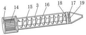
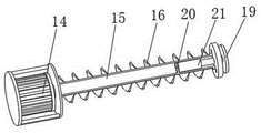
Wherein, 1, a workbench; 2. a support table; 3. an injection molding bin; 4. mounting a box; 5. a feed hopper; 6. an injection assembly; 601. a pressure cylinder; 602. a support bar; 603. a top plate; 604. a second hydraulic cylinder; 605. a platen; 606. a movable rod; 607. a piston; 7. a partition assembly; 701. a guide post; 702. a toothed plate; 703. mounting grooves; 704. a gear; 705. a slide bar; 706. a screw sleeve of the screw rod; 707. a screw rod; 708. a through groove; 709. a baffle plate; 710. a push plate; 711. a slider; 712. a chute; 713. a first limit groove; 714. a second limit groove; 8. a first hydraulic cylinder; 9. connecting blocks; 10. a template; 11. a guide bar; 12. a guide groove; 13. a mold plate; 14. a motor; 15. a rotating shaft; 16. conveying the spiral leaves; 17. positioning a plate; 18. a feed inlet; 19. a sealing plate; 20. a fixing plate; 21. a telescopic rod.
Detailed Description
The technical solutions in the embodiments of the present invention will be clearly and completely described below with reference to the drawings in the embodiments of the present invention, and it is obvious that the described embodiments are only a part of the embodiments of the present invention, and not all of the embodiments. All other embodiments, which can be derived by a person skilled in the art from the embodiments given herein without making any creative effort, shall fall within the protection scope of the present invention.
As shown in fig. 1-3, an embodiment of the invention provides an injection mold for plastic product production, which comprises a workbench 1, wherein a mold plate 13 is fixedly installed on the upper surface of the workbench 1, a first hydraulic cylinder 8 is fixedly installed on the upper surface of the mold plate 13, a mold plate 10 is fixedly installed at the output end of the first hydraulic cylinder 8, an injection bin 3 is installed on the upper surface of the workbench 1, a partition component 7 is arranged on the mold plate 13, an injection component 6 is arranged on the injection bin 3, an installation box 4 is fixedly installed at one end of the injection bin 3, a motor 14 is fixedly installed on the inner surface of the installation box 4, a rotating shaft 15 is installed at the output end of the motor 14, a conveying screw blade 16 is arranged on the side surface of the rotating shaft 15, a positioning plate 17 is fixedly installed on the inner wall at one end of the injection bin 3, and a feeding port 18 is formed in the positioning plate 17.
As shown in fig. 1, template 10 upper end fixed mounting has connecting block 9, the 8 output of first pneumatic cylinder sets up on connecting block 9, fixed surface installs brace table 2 on the 1 workstation, 3 fixed mounting in the storehouse of moulding plastics are at brace table 2 upper surface, be provided with feed hopper 5 on the storehouse 3 of moulding plastics, can guarantee the height in storehouse 3 of moulding plastics through 3 fixed mounting in the 2 upper surfaces of brace table in the storehouse of will moulding plastics, and the staff of being convenient for operates, through be provided with feed hopper 5 on the storehouse 3 of moulding plastics, can be convenient for the staff case 3 inside pour into the raw materials in storehouse of moulding plastics.
As shown in fig. 1, a guide groove 12 is formed in the upper surface of the workbench 1, a guide rod 11 is fixedly mounted on the template 10, the guide rod 11 is slidably mounted inside the guide groove 12, the guide rod 11 is slidably mounted in the guide groove 12, so that the stability of the template 10 can be ensured, and the stability is better when the template 10 moves.
As shown in fig. 5, a fixing plate 20 is fixedly mounted on the inner wall of the rotating shaft 15, an expansion rod 21 is fixedly mounted on the fixing plate 20, one end of the expansion rod 21 passes through the positioning plate 17, and a sealing plate 19 is fixedly mounted on the top end of the expansion rod 21, so that the sealing plate 19 can move backwards to block the feed inlet 18 by the pressure of the melted raw material during the injection process, thereby preventing the melted raw material from flowing backwards.
As shown in fig. 2 and 4, the injection assembly 6 includes a pressure cylinder 601 and a support rod 602, the injection molding bin 3 is provided with the pressure cylinder 601, the upper surface of the mold plate 13 is fixedly provided with the support rod 602, the inside of the pressure cylinder 601 is provided with a piston 607, the piston 607 is fixedly provided with a movable rod 606, the upper end of the movable rod 606 is fixedly provided with a pressure plate 605, the upper end of the support rod 602 is fixedly provided with a top plate 603, the lower surface of the top plate 603 is fixedly provided with a second hydraulic cylinder 604, the output end of the second hydraulic cylinder 604 is arranged on the pressure plate 605, the output end of the motor 14 rotates to drive the rotating shaft 15 to rotate, so as to rotate the conveying screw 16, the raw material is conveyed when the conveying screw 16 rotates, in the conveying process, the injection molding bin 3 is used for heating to melt the raw material, at this time, the melted raw material is continuously conveyed, the melted raw material will move forward from the feeding hole 18 and move into the pressure cylinder 601, at this time, the output end of the first hydraulic cylinder 8 extends and retracts to drive the template 10 to move, so that the template 10 and the mold plate 13 are attached together, thereby forming a mold cavity, when the template 10 moves, the guide column 701 also moves, thereby driving the toothed plate 702 to move, so that the gear 704 rotates, the screw rod 707 rotates, the screw rod nut 706 moves on the screw rod 707, the push plate 710 moves, the baffle 709 moves, so that the baffle 709 moves from the surface of the injection port, otherwise, the baffle 709 can be reset to block the injection port, so that the melted raw material can be prevented from entering the interior of the mold cavity when the injection is not performed, the next mold forming is affected, after the template 10 and the mold plate 13 are attached together, at this moment, the output end of the second hydraulic cylinder 604 stretches, so that the pressure plate 605 can be driven to move downwards, the piston 607 can be driven to move on the inner wall of the pressure cylinder 601, the melted raw materials in the pressure cylinder 601 can be injected into the mold cavity, the plastic processing is completed, and the efficiency of the plastic processing is improved.
As shown in fig. 6 and 7, the partition assembly 7 includes a guide post 701, an installation groove 703, a first limiting groove 713, and a second limiting groove 714, the mold plate 10 is fixedly installed with the guide post 701, the mold plate 13 is provided with the installation groove 703, the first limiting groove 713, and the second limiting groove 714, the guide post 701 movably penetrates through the installation groove 703, one end of the guide post 701 is fixedly installed with a toothed plate 702, a lead screw 707 is installed between inner walls of two sides of the second limiting groove 714, one end of the lead screw 707 is fixedly installed with a gear 704, the gear 704 is engaged with the toothed plate 702, the lead screw 707 is installed with a lead screw thread insert 706 in a sleeved manner, the inner surface of the installation groove 703 is provided with a sliding groove 712, the sliding block 711 is installed in the sliding groove 712, the upper end of the sliding block 711 is arranged on the lead screw thread insert 706, the inner surface of the second limiting groove 714 is provided with a through groove 708, the lower end of the lead screw thread insert 706 is installed with a pushing plate 710, the pushing plate 710 movably penetrates through the through groove 708 and is arranged inside the first limiting groove 713, the baffle 709 is fixedly arranged on the pushing plate 710, the slide rod 705 is fixedly arranged between the inner walls of the two sides of the second limiting groove 714, the screw rod threaded sleeve 706 is slidably arranged in the middle of the slide rod 705, raw materials enter the injection molding bin 3 from the feeding hopper 5, at the moment, the output end of the motor 14 rotates to drive the rotating shaft 15 to rotate, so that the conveying screw blade 16 rotates, the raw materials are conveyed when the conveying screw blade 16 rotates, in the conveying process, the injection molding bin 3 is heated to melt the raw materials, at the moment, the melted raw materials are continuously conveyed, the melted raw materials continuously move forwards from the feeding port 18 and move into the pressure cylinder 601, at the moment, the output end of the first hydraulic cylinder 8 stretches out and draws back to drive the template 10 to move, make template 10 and mould board 13 paste together, thereby form the die cavity, when template 10 removes, guide post 701 also removes, thereby drive pinion rack 702 and remove, make gear 704 rotate, make lead screw 707 rotate, make lead screw swivel 706 remove on lead screw 707, drive catch plate 710 and remove, make baffle 709 remove from the surface of the mouth of moulding plastics, otherwise can make baffle 709 reset and block the mouth of moulding plastics, prevent when not carrying out the injection, the raw materials that melts enter into the die cavity inside, influence next time mould shaping, through with lead screw swivel 706 slidable mounting in the middle part of slide bar 705, thereby can guarantee the stability when lead screw swivel 706 removes, after pasting together template 10 and mould board 13.
The working principle is as follows: firstly, raw materials enter an injection molding bin 3 from a feeding hopper 5, at the moment, the output end of a motor 14 rotates to drive a rotating shaft 15 to rotate, so that a conveying screw blade 16 rotates, the raw materials are conveyed when the conveying screw blade 16 rotates, in the conveying process, the injection molding bin 3 is heated to melt the raw materials, the melted raw materials are continuously conveyed at the moment, the melted raw materials continuously move forwards from a feeding hole 18 and move to the inside of a pressure cylinder 601, at the moment, the output end of a first hydraulic cylinder 8 stretches out and draws back to drive a template 10 to move, so that the template 10 and a mold plate 13 are attached together to form a mold cavity, when the template 10 moves, a guide column 701 also moves to drive a toothed plate 702 to move, a gear 704 rotates, a screw rod 707 rotates, and a screw sleeve 706 moves on the screw rod 707, the pushing plate 710 is driven to move, the baffle 709 is driven to move from the surface of the injection molding opening, otherwise, the baffle 709 can be reset to block the injection molding opening, molten raw materials are prevented from entering the inside of the mold cavity when no injection is performed, the next mold forming is influenced, after the template 10 and the mold plate 13 are attached together, the output end of the second hydraulic cylinder 604 stretches, the pressure plate 605 can be driven to move downwards, the piston 607 can be driven to move on the inner wall of the pressure cylinder 601, the molten raw materials in the pressure cylinder 601 can be injected into the mold cavity to complete the plastic processing, the processing efficiency of the device is high, the molten raw materials can be collected and continuously processed, the processing efficiency is improved, and in the injection process, the sealing plate 19 can be driven to move backwards to block the feed inlet 18 through the pressure of the molten raw materials, prevent that the condition of backward flow from appearing in the raw materials that melts, can guarantee the height in storehouse 3 of moulding plastics through 3 fixed mounting in the brace table 2 upper surfaces of storehouse of will moulding plastics, the staff of being convenient for operates, through be provided with feed hopper 5 on storehouse 3 of moulding plastics, the staff case of can being convenient for moulds plastics 3 inside pouring in raw materials in the storehouse, through having guide bar 11 slidable mounting have guide way 12, can guarantee the stability of template 10, stability is better when template 10 removes, the work efficiency of this device has been improved.
It should be understood that the above-mentioned embodiments of the present invention are only examples for clearly illustrating the present invention, and are not intended to limit the embodiments of the present invention, and it will be obvious to those skilled in the art that other variations and modifications can be made on the basis of the above description, and all embodiments cannot be exhaustive, and obvious variations and modifications may be made within the scope of the present invention.
Claims (10)
1. The utility model provides an injection mold is used in plastic products production, includes workstation (1), its characterized in that: a mould plate (13) is fixedly arranged on the upper surface of the workbench (1), a first hydraulic cylinder (8) is fixedly arranged on the upper surface of the mould plate (13), a template (10) is fixedly arranged at the output end of the first hydraulic cylinder (8), an injection molding bin (3) is arranged on the upper surface of the workbench (1), the mould plate (13) is provided with a partition component (7), the injection molding bin (3) is provided with an injection component (6), one end of the injection molding bin (3) is fixedly provided with a mounting box (4), the inner surface of the mounting box (4) is fixedly provided with a motor (14), the output end of the motor (14) is provided with a rotating shaft (15), the side surface of the rotating shaft (15) is provided with a conveying screw blade (16), the injection molding machine is characterized in that a positioning disc (17) is fixedly mounted on the inner wall of one end of the injection molding bin (3), and a feeding hole (18) is formed in the positioning disc (17).
2. The injection mold for producing plastic articles according to claim 1, wherein: the upper end of the template (10) is fixedly provided with a connecting block (9), and the output end of the first hydraulic cylinder (8) is arranged on the connecting block (9);
fixed surface installs brace table (2) on workstation (1), storehouse (3) fixed mounting of moulding plastics is at brace table (2) upper surface, be provided with feed hopper (5) on the storehouse (3) of moulding plastics.
3. The injection mold for producing plastic articles according to claim 1, wherein: guide way (12) have been seted up to workstation (1) upper surface, template (10) fixed mounting has guide bar (11), guide bar (11) slidable mounting has inside guide way (12).
4. The injection mold for producing plastic articles according to claim 1, wherein: the fixing device is characterized in that a fixing plate (20) is fixedly mounted on the inner wall of the rotating shaft (15), a telescopic rod (21) is fixedly mounted on the fixing plate (20), one end of the telescopic rod (21) penetrates through the positioning disc (17), and a sealing plate (19) is fixedly mounted at the top end of the telescopic rod (21).
5. The injection mold for producing plastic articles according to claim 1, wherein: the injection assembly (6) comprises a pressure cylinder (601) and a supporting rod (602), the injection molding bin (3) is provided with the pressure cylinder (601), and the supporting rod (602) is fixedly mounted on the upper surface of the mold plate (13).
6. The injection mold for producing plastic articles as claimed in claim 5, wherein: pressure cylinder (601) internally mounted has piston (607), fixed mounting has movable rod (606) on piston (607), movable rod (606) upper end fixed mounting has pressure disk (605).
7. The injection mold for producing plastic articles as claimed in claim 5, wherein: the upper end of the supporting rod (602) is fixedly provided with a top plate (603), the lower surface of the top plate (603) is fixedly provided with a second hydraulic cylinder (604), and the output end of the second hydraulic cylinder (604) is arranged on the pressure plate (605).
8. The injection mold for producing plastic articles according to claim 1, wherein: the partition component (7) comprises a guide post (701), a mounting groove (703), a first limiting groove (713) and a second limiting groove (714), the guide post (701) is fixedly mounted on the template (10), the mounting groove (703), the first limiting groove (713) and the second limiting groove (714) are arranged on the die plate (13), and the mounting groove (703) is movably penetrated through by the guide post (701).
9. An injection mold for producing plastic articles as claimed in claim 8, wherein: guide post (701) one end fixed mounting has pinion rack (702), install lead screw (707) between second spacing groove (714) both sides inner wall, lead screw (707) one end fixed mounting has gear (704), gear (704) are connected with pinion rack (702) meshing, the cover is established and is installed lead screw swivel nut (706) on lead screw (707), spout (712) have been seted up to mounting groove (703) internal surface, spout (712) inside slidable mounting has slider (711), slider (711) upper end sets up on lead screw swivel nut (706).
10. An injection mold for producing plastic articles as claimed in claim 9, wherein: a through groove (708) is formed in the inner surface of the second limiting groove (714), a pushing plate (710) is installed at the lower end of the screw rod thread sleeve (706), the pushing plate (710) movably penetrates through the through groove (708) and is arranged inside the first limiting groove (713), and a baffle (709) is fixedly installed on the pushing plate (710);
a sliding rod (705) is fixedly installed between the inner walls of the two sides of the second limiting groove (714), and the screw rod thread sleeve (706) is installed in the middle of the sliding rod (705) in a sliding mode.
Priority Applications (1)
| Application Number | Priority Date | Filing Date | Title |
|---|---|---|---|
| CN202210614824.2A CN114889052A (en) | 2022-06-01 | 2022-06-01 | Injection mold is used in plastic products production |
Applications Claiming Priority (1)
| Application Number | Priority Date | Filing Date | Title |
|---|---|---|---|
| CN202210614824.2A CN114889052A (en) | 2022-06-01 | 2022-06-01 | Injection mold is used in plastic products production |
Publications (1)
| Publication Number | Publication Date |
|---|---|
| CN114889052A true CN114889052A (en) | 2022-08-12 |
Family
ID=82726697
Family Applications (1)
| Application Number | Title | Priority Date | Filing Date |
|---|---|---|---|
| CN202210614824.2A Pending CN114889052A (en) | 2022-06-01 | 2022-06-01 | Injection mold is used in plastic products production |
Country Status (1)
| Country | Link |
|---|---|
| CN (1) | CN114889052A (en) |
Cited By (3)
| Publication number | Priority date | Publication date | Assignee | Title |
|---|---|---|---|---|
| CN116001134A (en) * | 2022-12-30 | 2023-04-25 | 重庆市大足区永彩装饰材料有限公司 | Preparation method and device of thermosetting plastic powder |
| CN118082132A (en) * | 2024-04-24 | 2024-05-28 | 泰州市同创装饰材料有限公司 | Plastic decoration injection molding equipment |
| CN118219489A (en) * | 2024-03-08 | 2024-06-21 | 托斯卡(江苏)新材料有限公司 | Quick injection moulding equipment of injection moulding product |
-
2022
- 2022-06-01 CN CN202210614824.2A patent/CN114889052A/en active Pending
Cited By (5)
| Publication number | Priority date | Publication date | Assignee | Title |
|---|---|---|---|---|
| CN116001134A (en) * | 2022-12-30 | 2023-04-25 | 重庆市大足区永彩装饰材料有限公司 | Preparation method and device of thermosetting plastic powder |
| CN116001134B (en) * | 2022-12-30 | 2024-05-28 | 重庆市大足区永彩装饰材料有限公司 | Preparation method and device of thermosetting plastic powder |
| CN118219489A (en) * | 2024-03-08 | 2024-06-21 | 托斯卡(江苏)新材料有限公司 | Quick injection moulding equipment of injection moulding product |
| CN118082132A (en) * | 2024-04-24 | 2024-05-28 | 泰州市同创装饰材料有限公司 | Plastic decoration injection molding equipment |
| CN118082132B (en) * | 2024-04-24 | 2024-09-06 | 泰州市同创装饰材料有限公司 | Plastic decoration injection molding equipment |
Similar Documents
| Publication | Publication Date | Title |
|---|---|---|
| CN114889052A (en) | Injection mold is used in plastic products production | |
| CN208148388U (en) | A kind of internal screw thread rotation depanning mold | |
| CN116037923A (en) | Production line of precision hot-pressing casting shaped product | |
| CN113172826B (en) | Integrated injection mold | |
| CN112959609B (en) | Mold with ejection mechanism for producing automobile speed sensor and use method thereof | |
| CN113524560A (en) | Speed-controllable injection molding system and injection molding process for electronic component product | |
| CN213500437U (en) | Injection molding machine injection molding device | |
| CN212603094U (en) | Novel combined injection mold | |
| CN212331730U (en) | High-efficient injection molding machine of twin-screw | |
| CN212193970U (en) | Feeding device for injection mold of automobile parts | |
| CN111645287A (en) | Injection molding system and injection molding method | |
| CN216068544U (en) | PC lamp face guard device of moulding plastics | |
| CN219466857U (en) | Combined injection mold | |
| CN221756773U (en) | Injection molding device for motor bracket plastic product | |
| CN214491474U (en) | Glue injection mold for multifunctional combined electric connector | |
| CN218948348U (en) | Ejection structure of injection mold | |
| CN218803638U (en) | Single-injection double-mold injection molding equipment with heating mechanism | |
| CN220576469U (en) | Through-flow injection molding plastic part integrated forming equipment | |
| CN215619355U (en) | Plastic mold convenient for molding and material taking | |
| CN212385943U (en) | Plastic injection molding equipment that heating efficiency is high | |
| CN209050933U (en) | A kind of plastic products special apparatus for working | |
| CN217021320U (en) | Ejection device for mold processing | |
| CN220784678U (en) | Injection molding machine nozzle with self-cleaning function | |
| CN218593572U (en) | High-precision thin-wall product injection mold | |
| CN219486464U (en) | Special injection molding machine for degradable material |
Legal Events
| Date | Code | Title | Description |
|---|---|---|---|
| PB01 | Publication | ||
| PB01 | Publication | ||
| SE01 | Entry into force of request for substantive examination | ||
| SE01 | Entry into force of request for substantive examination |