CN113524560A - Speed-controllable injection molding system and injection molding process for electronic component product - Google Patents
Speed-controllable injection molding system and injection molding process for electronic component product Download PDFInfo
- Publication number
- CN113524560A CN113524560A CN202110771664.8A CN202110771664A CN113524560A CN 113524560 A CN113524560 A CN 113524560A CN 202110771664 A CN202110771664 A CN 202110771664A CN 113524560 A CN113524560 A CN 113524560A
- Authority
- CN
- China
- Prior art keywords
- injection molding
- fixedly connected
- bin
- plate
- raw materials
- Prior art date
- Legal status (The legal status is an assumption and is not a legal conclusion. Google has not performed a legal analysis and makes no representation as to the accuracy of the status listed.)
- Pending
Links
- 238000001746 injection moulding Methods 0.000 title claims abstract description 254
- 239000004033 plastic Substances 0.000 claims abstract description 47
- 229920003023 plastic Polymers 0.000 claims abstract description 47
- 238000000465 moulding Methods 0.000 claims abstract description 40
- 239000002994 raw material Substances 0.000 claims description 104
- 238000003756 stirring Methods 0.000 claims description 35
- 238000007789 sealing Methods 0.000 claims description 20
- 238000002347 injection Methods 0.000 claims description 18
- 239000007924 injection Substances 0.000 claims description 18
- 238000010438 heat treatment Methods 0.000 claims description 14
- 229920000049 Carbon (fiber) Polymers 0.000 claims description 13
- 239000004917 carbon fiber Substances 0.000 claims description 13
- VNWKTOKETHGBQD-UHFFFAOYSA-N methane Chemical compound C VNWKTOKETHGBQD-UHFFFAOYSA-N 0.000 claims description 13
- 239000007788 liquid Substances 0.000 claims description 6
- 230000001105 regulatory effect Effects 0.000 claims description 6
- 230000001276 controlling effect Effects 0.000 claims description 5
- 238000004140 cleaning Methods 0.000 claims 1
- 230000007423 decrease Effects 0.000 claims 1
- 238000007790 scraping Methods 0.000 description 7
- 239000000428 dust Substances 0.000 description 4
- 239000000243 solution Substances 0.000 description 2
- 230000007547 defect Effects 0.000 description 1
- 239000000463 material Substances 0.000 description 1
- 238000000034 method Methods 0.000 description 1
- 239000002991 molded plastic Substances 0.000 description 1
- 238000007711 solidification Methods 0.000 description 1
- 230000008023 solidification Effects 0.000 description 1
- 229920001169 thermoplastic Polymers 0.000 description 1
- 229920001187 thermosetting polymer Polymers 0.000 description 1
Images


Classifications
-
- B—PERFORMING OPERATIONS; TRANSPORTING
- B29—WORKING OF PLASTICS; WORKING OF SUBSTANCES IN A PLASTIC STATE IN GENERAL
- B29C—SHAPING OR JOINING OF PLASTICS; SHAPING OF MATERIAL IN A PLASTIC STATE, NOT OTHERWISE PROVIDED FOR; AFTER-TREATMENT OF THE SHAPED PRODUCTS, e.g. REPAIRING
- B29C45/00—Injection moulding, i.e. forcing the required volume of moulding material through a nozzle into a closed mould; Apparatus therefor
- B29C45/03—Injection moulding apparatus
-
- B—PERFORMING OPERATIONS; TRANSPORTING
- B29—WORKING OF PLASTICS; WORKING OF SUBSTANCES IN A PLASTIC STATE IN GENERAL
- B29C—SHAPING OR JOINING OF PLASTICS; SHAPING OF MATERIAL IN A PLASTIC STATE, NOT OTHERWISE PROVIDED FOR; AFTER-TREATMENT OF THE SHAPED PRODUCTS, e.g. REPAIRING
- B29C45/00—Injection moulding, i.e. forcing the required volume of moulding material through a nozzle into a closed mould; Apparatus therefor
- B29C45/17—Component parts, details or accessories; Auxiliary operations
- B29C45/18—Feeding the material into the injection moulding apparatus, i.e. feeding the non-plastified material into the injection unit
-
- B—PERFORMING OPERATIONS; TRANSPORTING
- B29—WORKING OF PLASTICS; WORKING OF SUBSTANCES IN A PLASTIC STATE IN GENERAL
- B29C—SHAPING OR JOINING OF PLASTICS; SHAPING OF MATERIAL IN A PLASTIC STATE, NOT OTHERWISE PROVIDED FOR; AFTER-TREATMENT OF THE SHAPED PRODUCTS, e.g. REPAIRING
- B29C45/00—Injection moulding, i.e. forcing the required volume of moulding material through a nozzle into a closed mould; Apparatus therefor
- B29C45/17—Component parts, details or accessories; Auxiliary operations
- B29C45/76—Measuring, controlling or regulating
-
- B—PERFORMING OPERATIONS; TRANSPORTING
- B29—WORKING OF PLASTICS; WORKING OF SUBSTANCES IN A PLASTIC STATE IN GENERAL
- B29C—SHAPING OR JOINING OF PLASTICS; SHAPING OF MATERIAL IN A PLASTIC STATE, NOT OTHERWISE PROVIDED FOR; AFTER-TREATMENT OF THE SHAPED PRODUCTS, e.g. REPAIRING
- B29C45/00—Injection moulding, i.e. forcing the required volume of moulding material through a nozzle into a closed mould; Apparatus therefor
- B29C45/17—Component parts, details or accessories; Auxiliary operations
- B29C2045/1784—Component parts, details or accessories not otherwise provided for; Auxiliary operations not otherwise provided for
-
- B—PERFORMING OPERATIONS; TRANSPORTING
- B29—WORKING OF PLASTICS; WORKING OF SUBSTANCES IN A PLASTIC STATE IN GENERAL
- B29C—SHAPING OR JOINING OF PLASTICS; SHAPING OF MATERIAL IN A PLASTIC STATE, NOT OTHERWISE PROVIDED FOR; AFTER-TREATMENT OF THE SHAPED PRODUCTS, e.g. REPAIRING
- B29C2945/00—Indexing scheme relating to injection moulding, i.e. forcing the required volume of moulding material through a nozzle into a closed mould
- B29C2945/76—Measuring, controlling or regulating
- B29C2945/76494—Controlled parameter
- B29C2945/76545—Flow rate
-
- B—PERFORMING OPERATIONS; TRANSPORTING
- B29—WORKING OF PLASTICS; WORKING OF SUBSTANCES IN A PLASTIC STATE IN GENERAL
- B29C—SHAPING OR JOINING OF PLASTICS; SHAPING OF MATERIAL IN A PLASTIC STATE, NOT OTHERWISE PROVIDED FOR; AFTER-TREATMENT OF THE SHAPED PRODUCTS, e.g. REPAIRING
- B29C2945/00—Indexing scheme relating to injection moulding, i.e. forcing the required volume of moulding material through a nozzle into a closed mould
- B29C2945/76—Measuring, controlling or regulating
- B29C2945/76494—Controlled parameter
- B29C2945/76595—Velocity
Abstract
The invention belongs to the technical field of electronic component product processing, in particular to a speed-controllable electronic component product injection molding system and an injection molding process, and provides a scheme which comprises a bottom plate, wherein a conveying belt is arranged at the top of the bottom plate, a mold is arranged at the top of the conveying belt, a plurality of supporting legs are equidistantly distributed at the top of the bottom plate, an injection molding bin is fixedly connected to the top ends of the supporting legs, a feeding hopper is arranged at one side of the injection molding bin, a sliding cover plate is slidably connected to the top of the feeding hopper, and push plates are slidably connected to the inner walls of two sides of the injection molding bin. Avoid moulding plastics the rifle and block up influence later stage and mould plastics.
Description
Technical Field
The invention relates to the technical field of electronic component product processing, in particular to a speed-controllable electronic component product injection molding system and injection molding process.
Background
An injection molding machine is also known as an injection molding machine or an injection machine. It is a main forming equipment for making various shaped plastic products from thermoplastic plastics or thermosetting plastics by using plastic forming mould. The device is divided into a vertical type, a horizontal type and a full-electric type. The injection molding machine can heat plastic, apply high pressure to molten plastic, make it inject and fill the die cavity, when the existing injection molding machine is used, the sprue of the mould is butted with the nozzle of the injection molding device of the injection molding machine, then the molten plastic in the injection device is injected into the mould through the nozzle of the injection molding device.
The speed of moulding plastics and the flow of moulding plastics are unchangeable all the time when using, can't carry out appropriate adjustment according to the size of the product of treating moulding plastics, this kind of mode of moulding plastics at the uniform velocity has reduced the efficiency of moulding plastics undoubtedly, and after moulding plastics, the storehouse of moulding plastics is remained and is moulded plastics the raw materials of moulding plastics and place for a long time and can lead to moulding plastics the raw materials solidification, make the unable normal operating of injection molding machine, after moulding plastics in addition, the rifle of moulding plastics remaining raw materials of moulding plastics can solidify gradually, cause the rifle of moulding plastics to use.
Disclosure of Invention
The invention aims to solve the defects in the prior art, and provides a speed-controllable electronic zero device product injection molding system and an injection molding process, which have the advantages of compact structure, capability of regulating and controlling injection molding speed and injection molding flow, capability of preventing residual injection molding raw materials in an injection molding bin from being solidified and capability of easily replacing an injection molding gun.
In order to achieve the purpose, the invention adopts the following technical scheme:
a speed-controllable injection molding system for electronic component products comprises a bottom plate, a conveying belt is arranged at the top of the bottom plate, the top of the conveying belt is provided with a mould, the top of the bottom plate is provided with an injection molding bin, one side of the injection molding bin is provided with a feed hopper, the top of the feed hopper is connected with a sliding cover plate in a sliding way, the inner walls at the two sides of the injection molding bin are connected with push plates in a sliding way, the top of the injection molding bin is provided with a driving component for enabling the push plate to rotate and descend, one side of the injection molding bin is provided with a stirring component for stirring raw materials in the injection molding bin, the bottom of the injection molding bin is provided with an injection molding pipe communicated with the injection molding bin, one side of the injection molding bin is provided with a control component for controlling injection molding flow, the bottom in the storehouse of moulding plastics is equipped with the change subassembly that is used for changing the rifle of moulding plastics, the inside fixed dress in storehouse of moulding plastics is equipped with a plurality of carbon fiber heating tubes.
In the invention, the driving assembly comprises a rotating speed motor fixedly connected to the top of the injection molding bin, an output shaft of the rotating speed motor is fixedly connected with a worm, the top of the injection molding bin is rotatably connected with a sleeve, a nut is fixedly connected in the injection molding bin, a screw is connected in the nut in a threaded manner, the top end of the screw extends into the sleeve and is fixedly connected with a circular plate, two sides of the circular plate are respectively connected with the inner walls of two sides of the sleeve in a longitudinal sliding manner, a worm wheel is fixedly sleeved on the outer wall of the sleeve and is meshed with the worm, the bottom end of the screw extends into the injection molding bin and is fixedly connected with the top of a push plate, two symmetrical sliding grooves and sliding grooves are arranged in the push plate and are communicated with each other, scraping plates are respectively connected with the inner walls of two sides of the sliding grooves in a sliding manner, and two symmetrical first rotating rods are rotatably connected with two sides of the scraping plates, two equal sliding connection of both sides inner wall of sliding tray has two symmetrical sliders, four the top of slider all rotates with first rotation pole to be connected, two equal two symmetrical first extension springs of both sides inner wall fixedly connected with of sliding tray, four the one end that first extension spring is close to the scraper blade all with slider fixed connection.
According to the injection molding machine, the stirring assembly comprises a rotating motor fixedly connected to one side of an injection molding bin, a straight gear is fixedly connected to an output shaft of the rotating motor, concave plates are slidably connected to inner walls of two sides of the injection molding bin, a plurality of shifting plates are annularly and equidistantly arranged on the top of each concave plate, a circular groove is formed in the injection molding bin, a gear ring located in the circular groove is fixedly sleeved on the outer wall of each concave plate, one side, close to each concave plate, of the straight gear extends into the circular groove and is meshed with the gear ring, a circular support plate is fixedly connected to the inside of the injection molding tube, a stirring rod is rotatably connected to the center of the top of the circular support plate, the bottom end of the stirring rod penetrates through the circular support plate, and a plurality of stirring blades are annularly and equidistantly arranged on the outer wall of the stirring rod.
In the invention, the control component comprises a placing groove arranged on one side of the injection molding bin, an electric telescopic rod is arranged in the placing groove, a cylinder barrel of the electric telescopic rod is rotationally connected to one side wall of the placing groove, a base is fixedly connected with one side of the injection molding bin, a second rotating rod is rotationally connected in the base, a waist-shaped hole is arranged in the second rotating rod, the top end of the second rotating rod is rotationally connected with a piston rod of the electric telescopic rod, the bottom of the injection molding bin is fixedly connected with a connecting block, a connecting rod is connected in the connecting block in a sliding way, one side of the connecting rod is fixedly connected with a cylindrical block, one end of the cylindrical block extends into the waist-shaped hole of the second rotating rod and is in sliding connection with the waist-shaped hole of the second rotating rod, and the inner walls of the two sides of the injection molding pipe are connected with second baffles in a sliding manner, and one end, far away from the cylindrical block, of the connecting rod is fixedly connected with the second baffles.
According to the invention, the replacement assembly comprises two symmetrical cylindrical tables fixedly connected to the bottom of the injection molding bin, the outer walls of the two cylindrical tables are rotatably connected with V-shaped plates, the sides, close to each other, of the two V-shaped plates are fixedly connected with springs, the ends, far away from the springs, of the two V-shaped plates are fixedly connected with clamping blocks, and the sides, close to each other, of the two clamping blocks are in contact with the injection molding gun.
According to the injection molding bin, the liquid level meter is communicated with one side of the injection molding bin, the supporting legs are arranged on the top of the bottom plate at equal intervals, the top ends of the supporting legs are fixedly connected with the bottom of the injection molding bin, and raw materials in the injection molding bin can be observed through the liquid level meter.
According to the invention, the inner walls of the two sides of the injection molding bin are fixedly connected with the second sealing rings, the bottoms of the second sealing rings are in contact with the top of the concave plate, and the sealing property between the injection molding bin and the concave plate can be improved through the second sealing rings.
According to the invention, the outer wall of the push plate is fixedly sleeved with the first sealing ring, the first sealing ring is contacted with the inner wall of the injection molding bin, and the sealing property between the push plate and the injection molding bin can be improved through the first sealing ring.
According to the injection molding device, the hydraulic cylinder is fixedly connected to the top of the injection molding bin, a piston rod of the hydraulic cylinder is fixedly connected with the sliding cover plate, the raw material box is fixedly connected to the top of the injection molding bin, a communicated pipeline is arranged on one side of the raw material box, first baffle plates are slidably connected to the inner walls of the two sides of the bottom end of the pipeline, a vertical rod is fixedly connected to the bottom of each first baffle plate, a second tension spring is fixedly connected to one side of each vertical rod, one end, away from the sliding groove, of each second tension spring is fixedly connected with the pipeline, a rectangular groove is formed in the top of the sliding cover plate, and the bottom end of each vertical rod extends into the rectangular groove and is slidably connected with the rectangular groove.
An injection molding process of an injection molding system of a speed-controllable electronic component product comprises the following steps:
s1, a hydraulic cylinder is started, a piston rod of the hydraulic cylinder pushes a sliding cover plate to slide to the left side, a feed hopper is opened, a vertical rod slides in a rectangular groove, the right end of the rectangular groove is in contact with the vertical rod along with the sliding of the sliding cover plate, the rectangular groove drives the vertical rod and a second tension spring to move to the left side, the second tension spring starts to stretch, so that a pipeline is opened, raw materials in a raw material box enter an injection molding bin through the pipeline, after the raw materials in the injection molding bin are injected, the hydraulic cylinder is started, the piston rod of the hydraulic cylinder drives the sliding cover plate to slide rightwards, the sliding cover plate seals the feed hopper, dust in air is prevented from entering the injection molding bin, the quality of the raw materials in the injection molding bin is influenced, the vertical rod and the second tension spring reset under the action of the tension of the second tension spring, and the pipeline is sealed again;
s2, starting the electric telescopic rod, enabling a piston rod of the electric telescopic rod to contract to drive the second rotating rod to rotate, driving the second baffle and the connecting rod to slide to the left side by the bottom end of the second rotating rod along with the rotation of the second rotating rod, further opening the injection molding pipe, and driving the size of the injection molding pipe to be opened according to the specification of an injection molding product required, so that the flow rate of injection molding can be controlled;
s3, because the push plate is just above the raw material injection opening, the raw material is convenient to enter the injection molding bin through the feed hopper, then the rotating speed motor is started to drive the worm to rotate, the worm is meshed with the worm wheel, the worm drives the sleeve and the worm wheel to rotate, the two sides of the circular plate are respectively connected with the inner walls of the two sides of the sleeve in a longitudinal sliding mode, the screw is in threaded connection with the nut, along with the rotation of the sleeve, the screw drives the push plate to rotate and move downwards to extrude the raw material in the injection molding bin, the descending speed of the push plate can be regulated and controlled as required, the injection molding speed can be controlled, meanwhile, the push plate drives the scraper plate to rotate to stir the raw material in the injection molding bin, and the raw material is prevented from being solidified;
s4, the scraper plate descends along with the rotation of the push plate, when the scraper plate is contacted with the concave plate, the scraper plate is resisted by the concave plate, the scraper plate starts to slide upwards, the scraper plate drives the first rotating rod to rotate, the sliding block slides towards the middle, the first tension spring starts to stretch, the raw materials in the injection molding bin can be stirred through the scraper plate, and the raw materials in the concave plate can be cleaned, so that the raw materials are prevented from being wasted;
s5, after the injection molding is finished, and when the raw materials in the injection molding bin are too much, start the carbon fiber heating tube and rotate the motor, the carbon fiber heating tube heats the raw materials in the injection molding bin, it rotates the motor drive spur gear to rotate, because the top of concave plate is equipped with a plurality of boards of dialling, the concave plate drives the board of dialling and rotates, prevent that the raw materials in the injection molding bin from not using for a long time and solidifying, the concave plate stirs the raw materials rotation with the board of dialling, pivoted raw materials drive puddler and stirring leaf rotate, thereby prevent that the raw materials in the injection molding tube from solidifying, and remaining raw materials begin to solidify along with the time in the rifle of moulding plastics, lead to moulding plastics the rifle jam, press the V template this moment, the spring begins to compress, the clamp splice moves to the outside, remove the centre gripping of clamp splice to the rifle of moulding plastics, the rifle of moulding plastics drops from the injection molding tube, conveniently change the rifle of moulding plastics.
The invention has the following advantages:
1. the worm is driven to rotate by the starting speed motor, the screw drives the push plate to rotate and move downwards along with the rotation of the worm, raw materials in the injection molding bin are extruded, and the descending speed of the push plate can be regulated as required, so that the injection molding speed can be controlled.
2. When the screw rod drives the push pedal and rotates and moves downwards, the scraper blade rotates and moves downwards, the raw materials in the concave plate can be cleaned by stirring the raw materials in the injection molding bin through the scraper blade, and the raw materials are prevented from being wasted.
3. Starting electric telescopic handle, electric telescopic handle's piston rod shrink drives the second dwang and rotates, and then opens the pipe of moulding plastics through second baffle and connecting rod, and according to the specification of the product of moulding plastics as required, the size of the pipe of moulding plastics is opened in the drive to can control the flow of moulding plastics.
4. When the storehouse of moulding plastics remains too much raw materials, the start rotation motor, rotate the motor and pass through the spur gear and drive the notch board and rotate, stir the raw materials, start the carbon fiber heating tube and heat the raw materials after that to can prevent that the raw materials from solidifying.
5. When the injection molding gun is blocked due to residual raw materials in the injection molding gun, the V-shaped plate is pressed, the clamping of the injection molding gun is removed, and the injection molding gun is convenient to replace in time.
6. Starting the hydraulic cylinder, the piston rod of pneumatic cylinder promotes the sliding closure board and slides to the left side to can open feeder hopper and pipeline, during the raw materials in the raw materials case passes through the pipeline and gets into the storehouse of moulding plastics, after the raw materials injection, close pipeline and feeder hopper simultaneously, prevent that the dust in the air from getting into the storehouse of moulding plastics, influence the quality of raw materials in the storehouse of moulding plastics.
The injection molding gun has a simple structure, is convenient to operate, can control the flow speed and flow of injection molding according to injection molding requirements, can heat and stir the raw materials in the injection molding bin to prevent the raw materials from solidifying when the raw materials in the injection molding bin are excessive, and can be easily replaced when the injection molding gun is blocked by the raw materials, so that the influence of the blockage of the injection molding gun on later injection molding is avoided.
Drawings
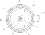
FIG. 1 is a front cross-sectional view of an injection molding system for a speed controllable electronic component product according to the present invention;
FIG. 2 is a rear view of an injection molding system for a speed controllable electronic component product according to the present invention;
FIG. 3 is a top view of an injection molding bin of an injection molding system for speed controllable electronic components according to the present invention;
FIG. 4 is a top view of a push plate of an injection molding system for a speed controllable electronic component product according to the present invention;
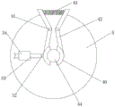
FIG. 5 is a sectional view taken along line A-A of an injection molding system for a speed controllable electronic component product according to the present invention;
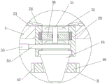
FIG. 6 is a top cross-sectional view of an injection molding bin of an injection molding system for a speed controllable electronic component product according to the present invention;
FIG. 7 is a top view of a circular groove and a toothed ring of an injection molding system for a speed controllable electronic component product according to the present invention;
FIG. 8 is a top cross-sectional view of an injection molded tube of an injection molding system for a controlled speed electronic component product in accordance with the present invention;
FIG. 9 is a bottom cross-sectional view of an injection molding hopper of an injection molding system for speed controllable electronic components of the present invention;
FIG. 10 is an enlarged view of a portion B of an injection molding system for a speed controllable electronic component product according to the present invention;
FIG. 11 is a top view of a replacement component of an injection molding system for a controlled speed electronic component product according to the present invention;
FIG. 12 is a three-dimensional view of a concave plate of an injection molding system for a speed controllable electronic component product according to the present invention;
FIG. 13 is a three-dimensional view of a clamping block of an injection molding system for a speed controllable electronic component product according to the present invention;
FIG. 14 is a front sectional view of a slide cover plate according to the second embodiment;
FIG. 15 is a top view of the injection molding cartridge of example two.
In the figure: 1. a base plate; 2. a conveyor belt; 3. a mold; 4. supporting legs; 5. an injection molding bin; 6. a feed hopper; 7. a sliding cover plate; 8. a nut; 9. a screw; 10. a circular plate; 11. a sleeve; 12. a worm gear; 13. a rotating speed motor; 14. a worm; 15. pushing the plate; 16. a chute; 17. a squeegee; 18. a sliding groove; 19. a slider; 20. a first tension spring; 21. a first rotating lever; 22. a carbon fiber heating tube; 23. a concave plate; 24. dialing a plate; 25. a circular groove; 26. a toothed ring; 27. a spur gear; 28. rotating the motor; 29. injection molding a tube; 30. a circular support plate; 31. a stirring rod; 32. stirring blades; 33. a connecting rod; 34. connecting blocks; 35. a placement groove; 36. an electric telescopic rod; 37. a base; 38. a second rotating lever; 39. a cylindrical block; 40. a clamping block; 41. a cylindrical table; 42. a V-shaped plate; 43. a spring; 44. an injection molding gun; 45. a raw material tank; 46. a pipeline; 47. a first baffle plate; 48. a vertical rod; 49. a second tension spring; 50. a rectangular groove; 51. a hydraulic cylinder; 52. a second baffle; 53. a liquid level meter; 54. a first seal ring; 55. a second seal ring; 56. a guide rail; 57. a slide block.
Detailed Description
The technical solutions in the embodiments of the present invention will be clearly and completely described below with reference to the drawings in the embodiments of the present invention, and it is obvious that the described embodiments are only a part of the embodiments of the present invention, and not all of the embodiments.
Example one
Referring to fig. 1-13, a controllable speed type electronic component product injection molding system comprises a base plate 1, a conveyor belt 2 is arranged at the top of the base plate 1, a mold 3 is arranged at the top of the conveyor belt 2, an injection molding bin 5 is arranged at the top of the base plate 1, a feed hopper 6 is arranged at one side of the injection molding bin 5, a sliding cover plate 7 is slidably connected to the top of the feed hopper 6, push plates 15 are slidably connected to the inner walls of the two sides of the injection molding bin 5, a driving component for enabling the push plates 15 to rotate and descend is arranged at the top of the injection molding bin 5, a stirring component for stirring raw materials in the injection molding bin 5 is arranged at one side of the injection molding bin 5, an injection molding pipe 29 communicated with each other is arranged at the bottom of the injection molding bin 5, a control component for controlling injection molding flow is arranged at one side of the injection molding bin 5, a replacing component for replacing an injection molding gun 44 is arranged at the bottom of the injection molding bin 5, and a plurality of carbon fiber heating pipes 22 are fixedly embedded in the injection molding bin 5.
In the invention, the driving component comprises a rotating speed motor 13 fixedly connected to the top of an injection molding bin 5, an output shaft of the rotating speed motor 13 is fixedly connected with a worm 14, the top of the injection molding bin 5 is rotatably connected with a sleeve 11, a nut 8 is fixedly connected in the injection molding bin 5, a screw 9 is connected in the nut 8 in a threaded manner, the top end of the screw 9 extends into the sleeve 11 and is fixedly connected with a circular plate 10, two sides of the circular plate 10 are fixedly provided with a slide block 57, two side inner walls of the sleeve 11 are fixedly provided with a guide rail 56, the slide block 57 is in sliding connection with the guide rail 56, two sides of the circular plate 10 are respectively in longitudinal sliding connection with two side inner walls of the sleeve 11, the outer wall of the sleeve 11 is fixedly sleeved with a worm wheel 12, the worm wheel 12 is meshed with the worm 14, the bottom end of the screw 9 extends into the injection molding bin 5 and is fixedly connected with the top of a push plate 15, two symmetrical sliding chutes 16 and sliding chutes 18 are arranged in the push plate 15, chute 16 and sliding tray 18 are linked together, the equal sliding connection of the both sides inner wall of two chutes 16 has scraper blade 17, the both sides rotation of two scraper blades 17 is connected with two symmetrical first rotation poles 21, the equal sliding connection of the both sides inner wall of two sliding tray 18 has two symmetrical sliders 19, the top of four sliders 19 all rotates with first rotation pole 21 to be connected, the equal fixedly connected with two symmetrical first extension springs 20 of the both sides inner wall of two sliding tray 18, four first extension springs 20 are close to the one end of scraper blade 17 and all with slider 19 fixed connection.
According to the invention, the stirring assembly comprises a rotating motor 28 fixedly connected to one side of the injection molding bin 5, an output shaft of the rotating motor 28 is fixedly connected with a straight gear 27, the inner walls of two sides of the injection molding bin 5 are connected with concave plates 23 in a sliding mode, a plurality of shifting plates 24 are annularly and equidistantly arranged on the top of each concave plate 23, a circular groove 25 is formed in the injection molding bin 5, a toothed ring 26 located in the circular groove 25 is fixedly sleeved on the outer wall of each concave plate 23, one side, close to each concave plate 23, of each straight gear 27 extends into the circular groove 25 and is meshed with the toothed ring 26, a circular support plate 30 is fixedly connected in the injection molding tube 29, a stirring rod 31 is rotatably connected to the center of the top of the circular support plate 30, the bottom end of the stirring rod 31 penetrates through the circular support plate 30, and a plurality of stirring blades 32 are annularly and equidistantly arranged on the outer wall of the stirring rod 31.
According to the invention, the control assembly comprises a placing groove 35 arranged on one side of the injection molding bin 5, an electric telescopic rod 36 is arranged in the placing groove 35, a cylinder barrel of the electric telescopic rod 36 is rotatably connected to one side wall of the placing groove 35, one side of the injection molding bin 5 is fixedly connected with a base 37, a second rotating rod 38 is rotatably connected to the base 37, the top end of the second rotating rod 38 is rotatably connected with a piston rod of the electric telescopic rod 36, the bottom of the injection molding bin 5 is fixedly connected with a connecting block 34, a connecting rod 33 is slidably connected with the connecting block 34, one side of the connecting rod 33 is fixedly connected with a cylindrical block 39, one end of the cylindrical block 39 extends into the second rotating rod 38 and is slidably connected with the second rotating rod 38, the inner walls on two sides of the injection molding tube 29 are slidably connected with second baffles 52, and one end of the connecting rod 33 far away from the cylindrical block 39 is fixedly connected with the second baffles 52.
According to the invention, the replacing assembly comprises two symmetrical cylindrical tables 41 fixedly connected to the bottom of the injection molding bin 5, the outer walls of the two cylindrical tables 41 are rotatably connected with V-shaped plates 42, one sides, close to each other, of the two V-shaped plates 42 are fixedly connected with springs 43, one ends, far away from the springs 43, of the two V-shaped plates 42 are fixedly connected with clamping blocks 40, and one sides, close to each other, of the two clamping blocks 40 are in contact with an injection molding gun 44.
In the invention, one side of the injection molding bin 5 is provided with a liquid level meter 53 which is communicated with the injection molding bin, a plurality of supporting feet 4 are equidistantly arranged on the top of the bottom plate 1, the top ends of the supporting feet 4 are fixedly connected with the bottom of the injection molding bin 5, and raw materials in the injection molding bin 5 can be observed through the liquid level meter 53.
In the invention, the inner walls of two sides of the injection molding bin 5 are fixedly connected with the second sealing rings 55, the bottoms of the second sealing rings 55 are contacted with the top of the concave plate 23, and the sealing property between the injection molding bin 5 and the concave plate 23 can be improved through the second sealing rings 55.
In the invention, the outer wall of the push plate 15 is fixedly sleeved with the first sealing ring 54, the first sealing ring 54 is contacted with the inner wall of the injection molding bin 5, and the sealing property between the push plate 15 and the injection molding bin 5 can be improved through the first sealing ring 54.
An injection molding process of an injection molding system of a speed-controllable electronic component product comprises the following steps:
s1, a hydraulic cylinder 51 is started, a piston rod of the hydraulic cylinder 51 pushes a sliding cover plate 7 to slide towards the left side, a feed hopper 6 is opened, a vertical rod 48 slides in a rectangular groove 50, along with the sliding of the sliding cover plate 7, the right end of the rectangular groove 50 is in contact with the vertical rod 48, the rectangular groove 50 drives the vertical rod 48 and a second tension spring 49 to move towards the left side, the second tension spring 49 starts to stretch, so that a pipeline 46 is opened, raw materials in a raw material box 45 are pumped into the pipeline 46 through a material pump and enter an injection molding bin 5, after the injection of the raw materials in the injection molding bin 5 is finished, the hydraulic cylinder 51 is started, the piston rod of the hydraulic cylinder 51 drives the sliding cover plate 7 to slide towards the right side, so that the sliding cover plate 7 seals the feed hopper 6, dust in air is prevented from entering the injection molding bin 5 to influence the quality of the raw materials in the injection molding bin 5, and the vertical rod 48 and the second tension spring 49 reset under the tension of the second tension spring 49 to close the pipeline 46 again;
s2, starting the electric telescopic rod 36, enabling the piston rod of the electric telescopic rod 36 to contract to drive the second rotating rod 38 to rotate, driving the second baffle plate 52 and the connecting rod 33 to slide to the left side by the bottom end of the second rotating rod 38 along with the rotation of the second rotating rod 38, further opening the injection molding pipe 29, and controlling the size of the injection molding pipe 29 to be opened according to the specification of the injection molding product required, so that the injection molding flow can be controlled;
s3, because the push plate 15 is just positioned above the raw material injection opening, the raw materials can conveniently enter the injection molding bin 5 through the feed hopper 6, then the rotating speed motor 13 is started to drive the worm 14 to rotate, the worm 14 is meshed with the worm wheel 12, the worm 14 drives the sleeve 11 and the worm wheel 12 to rotate, the circular plate 10 is in sliding connection with the inner wall of the sleeve 11, the screw 9 is in threaded connection with the nut 8, along with the rotation of the sleeve 11, the screw 9 drives the push plate 15 to rotate and move downwards to extrude the raw materials in the injection molding bin 5, the descending speed of the push plate 15 can be regulated and controlled as required, so that the injection molding speed can be controlled, meanwhile, the push plate 15 drives the scraper 17 to rotate, the raw materials in the injection molding bin 5 are stirred, and the raw materials are prevented from being solidified;
s4, the rotating and descending of the push plate 15, when the scraping plate 17 touches the concave plate 23, the scraping plate 17 is resisted by the concave plate 23, the scraping plate 17 starts to slide upwards, at the moment, the scraping plate 17 drives the first rotating rod 21 to rotate, the sliding block 19 slides towards the middle, the first tension spring 20 starts to stretch, the scraping plate 17 can not only stir the raw materials in the injection molding bin 5, but also clean the raw materials in the concave plate 23, and the raw materials are prevented from being wasted;
s5, when the injection molding is finished and the raw material in the injection molding bin 5 is excessive, starting the carbon fiber heating tube 22 and the rotating motor 28, heating the raw material in the injection molding bin 5 by the carbon fiber heating tube 22, driving the spur gear 27 to rotate by the rotating motor 28, because the top of the concave plate 23 is provided with a plurality of shifting plates 24, the concave plate 23 drives the shifting plates 24 to rotate, the raw materials in the injection molding bin 5 are prevented from solidifying after being unused for a long time, the concave plate 23 and the shifting plates 24 stir the raw materials to rotate, the rotating raw materials drive the stirring rod 31 and the stirring blades 32 to rotate, therefore, the raw material in the injection pipe 29 is prevented from being solidified, the raw material remained in the injection gun 44 begins to be solidified along with time, the injection gun 44 is blocked, the V-shaped plate 42 is pressed, the spring 43 begins to be compressed, the clamping block 40 moves outwards, the clamping of the clamping block 40 on the injection gun 44 is released, the injection gun 44 falls off from the injection pipe 29, and the injection gun 44 is convenient to replace.
Example two: as shown in fig. 14-15, the present embodiment is different from the first embodiment in that: the top fixedly connected with pneumatic cylinder 51 in storehouse 5 of moulding plastics, pneumatic cylinder 51's piston rod and sliding closure 7 fixed connection, the top fixedly connected with raw material tank 45 in storehouse 5 of moulding plastics, one side of raw material tank 45 is equipped with the pipeline 46 that is linked together, the first baffle 47 of bottom both sides inner wall sliding connection of pipeline 46, the bottom fixedly connected with montant 48 of first baffle 47, one side fixedly connected with second extension spring 49 of montant 48, sliding groove 18's one end and pipeline 46 fixed connection are kept away from to bottom second extension spring 49, sliding closure 7's top is equipped with rectangular channel 50, montant 48's bottom extend to in the rectangular channel 50 and with rectangular channel 50 sliding connection.
However, as is well known to those skilled in the art, the working principle and wiring method of the rotating speed motor 13, the rotating motor 28, the electric telescopic rod 36 and the hydraulic cylinder 51 are common and are conventional means or common knowledge, and thus they will not be described herein again, and those skilled in the art can make any choice according to their needs or convenience.
The working principle is as follows: the first step, the hydraulic cylinder 51 is started, the piston rod of the hydraulic cylinder 51 pushes the sliding cover plate 7 to slide to the left side, the feeding hopper 6 is opened, the vertical rod 48 slides in the rectangular groove 50, along with the sliding of the sliding cover plate 7, the right end of the rectangular groove 50 touches the vertical rod 48, the rectangular groove 50 drives the vertical rod 48 and the second tension spring 49 to move to the left side, the second tension spring 49 starts to stretch, so that the pipeline 46 is opened, the raw material in the raw material box 45 enters the injection molding bin 5 through the pipeline 46, after the injection of the raw material in the injection molding bin 5 is finished, the hydraulic cylinder 51 is started, the piston rod of the hydraulic cylinder 51 drives the sliding cover plate 7 to slide to the right side, so that the sliding cover plate 7 seals the feeding hopper 6, the dust in the air is prevented from entering the injection molding bin 5 to influence the quality of the raw material in the injection molding bin 5, the vertical rod 48 and the second tension spring 49 reset under the tension of the second tension spring 49, the pipeline 46 is re-sealed, the second step, the electric telescopic rod 36 is started, the piston rod of the electric telescopic rod 36 contracts to drive the second rotating rod 38 to rotate, along with the rotation of the second rotating rod 38, the bottom end of the second rotating rod 38 drives the second baffle plate 52 and the connecting rod 33 to slide towards the left side, so as to open the injection molding pipe 29, according to the specification of the injection molding product, the size of the injection molding pipe 29 is driven to be opened, so that the injection molding flow can be controlled, in the third step, as the push plate 15 is just positioned above the raw material injection opening, the raw material can conveniently enter the injection molding bin 5 through the feed hopper 6, then the rotating speed motor 13 is started to drive the worm 14 to rotate, the worm 14 is meshed with the worm wheel 12, the worm 14 drives the sleeve 11 and the worm wheel 12 to rotate, the circular plate 10 is connected with the inner wall of the sleeve 11 in a sliding manner, the screw rod 9 is connected with the nut 8 in a threaded manner, along with the rotation of the sleeve 11, the screw rod 9 drives the push plate 15 to rotate downwards to extrude the raw material in the injection molding bin 5, the speed of the push plate 15 descending can be regulated and controlled as required, thereby the injection molding speed can be controlled, simultaneously the push plate 15 drives the scraper 17 to rotate, the raw materials in the injection molding bin 5 are stirred, the raw materials are prevented from being solidified, in the fourth step, along with the rotation descending of the push plate 15, when the scraper 17 is contacted with the concave plate 23, the scraper 17 is resisted by the concave plate 23, the scraper 17 starts to slide upwards, at the moment, the scraper 17 drives the first rotating rod 21 to rotate, the sliding block 19 slides towards the middle, the first tension spring 20 starts to stretch, the raw materials in the injection molding bin 5 can be stirred through the scraper 17, the raw materials in the concave plate 23 can be cleaned, the raw materials are prevented from being wasted, in the fifth step, when the injection molding is finished and the raw materials in the injection molding bin 5 are too much, the carbon fiber heating tube 22 and the rotating motor 28 are started, the carbon fiber heating tube 22 heats the raw materials in the injection molding bin 5, the rotating motor 28 drives the straight gear 27 to rotate, because the top of the concave plate 23 is provided with the plurality of shifting plates 24, the concave plate 23 drives the shifting plates 24 to rotate, the raw materials in the injection molding bin 5 are prevented from solidifying due to long-time non-use, the concave plate 23 and the shifting plates 24 stir the raw materials to rotate, the rotating raw materials drive the stirring rod 31 and the stirring blade 32 to rotate, so that the raw materials in the injection molding pipe 29 are prevented from solidifying, the residual raw materials in the injection molding gun 44 begin to solidify along with time, the injection molding gun 44 is blocked, the V-shaped plate 42 is pressed at the moment, the spring 43 begins to compress, the clamping block 40 moves outwards, the clamping of the clamping block 40 on the injection molding gun 44 is released, the injection molding gun 44 falls off from the injection molding pipe 29, and the injection molding gun 44 is convenient to replace.
The above description is only for the preferred embodiment of the present invention, but the scope of the present invention is not limited thereto, and any person skilled in the art should be considered to be within the technical scope of the present invention, and the technical solutions and the inventive concepts thereof according to the present invention should be equivalent or changed within the scope of the present invention.
Claims (10)
1. The utility model provides a controllable speed type electron spare part product injection molding system, includes bottom plate (1), its characterized in that, the top of bottom plate (1) is provided with conveyer belt (2), the top of conveyer belt (2) is provided with mould (3), the top of bottom plate (1) is provided with one and moulds plastics storehouse (5), one side of moulding plastics storehouse (5) is equipped with feeder hopper (6), the top sliding connection of feeder hopper (6) has sliding closure board (7), the both sides inner wall sliding connection of storehouse of moulding plastics (5) has push pedal (15), the top of storehouse of moulding plastics (5) is equipped with the drive assembly that is used for making push pedal (15) rotatory decline, one side of storehouse of moulding plastics (5) is equipped with the stirring subassembly that is used for stirring to the raw materials in storehouse of moulding plastics (5), the bottom in storehouse of moulding plastics (5) is equipped with injection molding pipe (29) that are linked together, one side in storehouse (5) of moulding plastics is equipped with the control assembly that is used for controlling the flow of moulding plastics, the bottom of the injection molding bin (5) is provided with a replacing component for replacing an injection molding gun (44), and a plurality of carbon fiber heating tubes (22) are fixedly embedded in the injection molding bin (5).
2. The injection molding system of the controllable-speed electronic zero device product as claimed in claim 1, wherein the driving assembly comprises a rotating speed motor (13) fixedly connected to the top of the injection molding bin (5), an output shaft of the rotating speed motor (13) is fixedly connected with a worm (14), the top of the injection molding bin (5) is rotatably connected with a sleeve (11), a nut (8) is fixedly connected in the injection molding bin (5), a screw (9) is connected in the nut (8) in a threaded manner, the top end of the screw (9) extends into the sleeve (11) and is fixedly connected with a circular plate (10), two sides of the circular plate (10) are respectively connected with inner walls of two sides of the sleeve (11) in a longitudinal sliding manner, a worm wheel (12) is fixedly sleeved on the outer wall of the sleeve (11), the worm wheel (12) is meshed with the worm (14), the bottom end of the screw (9) extends into the injection molding bin (5) and is fixedly connected with the top of the push plate (15), be provided with two symmetrical spout (16) and sliding tray (18) in push pedal (15), spout (16) and sliding tray (18) are linked together, two the equal sliding connection of both sides inner wall of spout (16) has scraper blade (17), two the both sides rotation of scraper blade (17) is connected with two symmetrical first rotation pole (21), two the equal sliding connection of both sides inner wall of sliding tray (18) has two symmetrical slider (19), four the top of slider (19) all rotates with first rotation pole (21) to be connected, two the equal fixedly connected with two symmetrical first extension spring (20) of both sides inner wall of sliding tray (18), four the one end that first extension spring (20) is close to scraper blade (17) all with slider (19) fixed connection.
3. The injection molding system of the speed-controllable electronic component product of claim 1, wherein the stirring assembly comprises a rotating motor (28) fixedly connected to one side of the injection molding bin (5), an output shaft of the rotating motor (28) is fixedly connected with a spur gear (27), inner walls of two sides of the injection molding bin (5) are slidably connected with concave plates (23), a plurality of shifting plates (24) are annularly and equidistantly arranged at the top of the concave plates (23), a circular groove (25) is arranged in the injection molding bin (5), a toothed ring (26) positioned in the circular groove (25) is fixedly sleeved on the outer wall of the concave plates (23), one side of the spur gear (27) close to the concave plates (23) extends into the circular groove (25) and is meshed with the toothed ring (26), a circular support plate (30) is fixedly connected in the injection molding pipe (29), a top rotating center of the circular support plate (30) is connected with a stirring rod (31), circular extension board (30) are run through to the bottom of puddler (31), a plurality of stirring leaves (32) have been arranged to the outer wall annular equidistance of puddler (31).
4. The injection molding system of the controllable speed electronic component product according to claim 1, wherein the control assembly comprises a placement groove (35) disposed on one side of the injection molding bin (5), an electric telescopic rod (36) is disposed in the placement groove (35), a cylinder of the electric telescopic rod (36) is rotatably connected to one side wall of the placement groove (35), a base (37) is fixedly connected to one side of the injection molding bin (5), a second rotating rod (38) is rotatably connected to the base (37), a waist-shaped hole is disposed in the second rotating rod (38), a top end of the second rotating rod (38) is rotatably connected to a piston rod of the electric telescopic rod (36), a connecting block (34) is fixedly connected to the bottom of the injection molding bin (5), a connecting rod (33) is slidably connected to the connecting block (34), and a cylindrical block (39) is fixedly connected to one side of the connecting rod (33), one end of the cylindrical block (39) extends to the waist-shaped hole of the second rotating rod (38) and is in sliding connection with the waist-shaped hole of the second rotating rod (38), the inner walls of the two sides of the injection molding pipe (29) are in sliding connection with a second baffle (52), and one end of the connecting rod (33) far away from the cylindrical block (39) is fixedly connected with the second baffle (52).
5. The injection molding system of the controllable speed type electronic component product as claimed in claim 1, wherein the replacement assembly comprises two symmetrical cylindrical tables (41) fixedly connected to the bottom of the injection molding bin (5), the outer walls of the two cylindrical tables (41) are rotatably connected with V-shaped plates (42), one sides of the two V-shaped plates (42) close to each other are fixedly connected with springs (43), one ends of the two V-shaped plates (42) far away from the springs (43) are fixedly connected with clamping blocks (40), and one sides of the two clamping blocks (40) close to each other are contacted with the injection molding gun (44).
6. The injection molding system of the speed-controllable electronic zero device product according to claim 1, wherein a liquid level meter (53) communicated with the injection molding bin (5) is arranged on one side of the injection molding bin (5), a plurality of supporting feet (4) are equidistantly arranged on the top of the bottom plate (1), and the top ends of the supporting feet (4) are fixedly connected with the bottom of the injection molding bin (5).
7. The injection molding system of the controllable speed electronic component product according to claim 3, wherein the inner walls of the two sides of the injection molding bin (5) are fixedly connected with second sealing rings (55), and the bottoms of the second sealing rings (55) are in contact with the top of the concave plate (23).
8. The injection molding system of the speed controllable electronic component product as claimed in claim 1, wherein the outer wall of the push plate (15) is fixedly sleeved with a first sealing ring (54), and the first sealing ring (54) touches the inner wall of the injection molding bin (5).
9. The injection molding system of claim 1, wherein, the top of the injection molding bin (5) is fixedly connected with a hydraulic cylinder (51), a piston rod of the hydraulic cylinder (51) is fixedly connected with a sliding cover plate (7), the top of the injection molding bin (5) is fixedly connected with a raw material box (45), one side of the raw material box (45) is provided with a pipeline (46) communicated with each other, the inner walls of two sides of the bottom end of the pipeline (46) are connected with a first baffle (47) in a sliding way, a vertical rod (48) is fixedly connected to the bottom of the first baffle (47), a second tension spring (49) is fixedly connected to one side of the vertical rod (48), one end, far away from the sliding groove (18), of the second tension spring (49) at the bottom end is fixedly connected with the pipeline (46), the top of sliding cover board (7) is equipped with rectangular channel (50), the bottom of montant (48) extends to in rectangular channel (50) and with rectangular channel (50) sliding connection.
10. An injection molding process of an injection molding system for a speed controllable electronic component product according to any one of claims 1 to 9, characterized in that: it comprises the following steps:
s1, starting a hydraulic cylinder (51), wherein a piston rod of the hydraulic cylinder (51) pushes a sliding cover plate (7) to slide to the left side, a feed hopper (6) is opened, raw materials in a raw material box (45) enter an injection molding bin (5) through a pipeline (46), after the injection of the raw materials in the injection molding bin (5) is finished, the hydraulic cylinder (51) is started, the piston rod of the hydraulic cylinder (51) drives the sliding cover plate (7) to slide rightwards, the sliding cover plate (7) seals the feed hopper (6), a vertical rod (48) and a second tension spring (49) reset under the tension of the second tension spring (49), and the pipeline (46) is closed again;
s2, starting the electric telescopic rod (36), enabling a piston rod of the electric telescopic rod (36) to contract to drive the second rotating rod (38) to rotate, enabling the bottom end of the second rotating rod (38) to drive the second baffle plate (52) and the connecting rod (33) to slide to the left side along with the rotation of the second rotating rod (38), further opening the injection molding pipe (29), and driving the size of the injection molding pipe (29) to be opened according to the specification of the injection molding product required, so that the flow rate of injection molding can be controlled;
s3, the push plate (15) is just above the raw material injection opening, so that the raw materials can enter the injection molding bin (5) through the feed hopper (6), then the rotating speed motor (13) is started to drive the push plate (15) to rotate and move downwards, the raw materials in the injection molding bin (5) are extruded, the descending speed of the push plate (15) can be regulated and controlled as required, the injection molding speed can be controlled, meanwhile, the push plate (15) drives the scraper (17) to rotate, the raw materials in the injection molding bin (5) are stirred, and the raw materials are prevented from being solidified;
s4, the scraper (17) descends along with the rotation of the push plate (15), when the scraper (17) is in contact with the concave plate (23), the scraper (17) is resisted by the concave plate (23), the scraper (17) starts to slide upwards, the scraper (17) drives the first rotating rod (21) to rotate at the moment, the sliding block (19) slides towards the middle, the first tension spring (20) starts to stretch, the scraper (17) can be used for stirring the raw materials in the injection molding bin (5) and cleaning the raw materials in the concave plate (23), and the raw materials are prevented from being wasted;
s5, after injection molding is finished, when the raw materials in the injection molding bin (5) are excessive, the carbon fiber heating tube (22) and the rotating motor (28) are started, the carbon fiber heating tube (22) heats the raw materials in the injection molding bin (5), the rotating motor (28) drives the shifting plate (24) to rotate, the raw materials in the injection molding bin (5) are prevented from solidifying due to long-time non-use, the V-shaped plate (42) is pressed at the moment, the spring (43) starts to be compressed, the clamping block (40) moves outwards, the clamping of the clamping block (40) on the injection molding gun (44) is released, the injection molding gun (44) falls off from the injection molding tube (29), and the injection molding gun (44) is convenient to replace.
Priority Applications (1)
| Application Number | Priority Date | Filing Date | Title |
|---|---|---|---|
| CN202110771664.8A CN113524560A (en) | 2021-07-08 | 2021-07-08 | Speed-controllable injection molding system and injection molding process for electronic component product |
Applications Claiming Priority (1)
| Application Number | Priority Date | Filing Date | Title |
|---|---|---|---|
| CN202110771664.8A CN113524560A (en) | 2021-07-08 | 2021-07-08 | Speed-controllable injection molding system and injection molding process for electronic component product |
Publications (1)
| Publication Number | Publication Date |
|---|---|
| CN113524560A true CN113524560A (en) | 2021-10-22 |
Family
ID=78127136
Family Applications (1)
| Application Number | Title | Priority Date | Filing Date |
|---|---|---|---|
| CN202110771664.8A Pending CN113524560A (en) | 2021-07-08 | 2021-07-08 | Speed-controllable injection molding system and injection molding process for electronic component product |
Country Status (1)
| Country | Link |
|---|---|
| CN (1) | CN113524560A (en) |
Cited By (2)
| Publication number | Priority date | Publication date | Assignee | Title |
|---|---|---|---|---|
| CN114055666A (en) * | 2021-11-15 | 2022-02-18 | 满运昭 | Waste plastic melting granulator |
| CN115214094A (en) * | 2022-06-13 | 2022-10-21 | 兴邦新材料(山东)有限公司 | TPU chopping board injection molding process and device |
Citations (5)
| Publication number | Priority date | Publication date | Assignee | Title |
|---|---|---|---|---|
| US5662952A (en) * | 1993-02-02 | 1997-09-02 | Tpp Axxicon B.V. | Injection mould with a pre-opening jack |
| CN102814921A (en) * | 2011-12-31 | 2012-12-12 | 洛阳智颢工程塑料有限公司 | High-pressure reaction injection moulding device |
| CN208375787U (en) * | 2018-01-11 | 2019-01-15 | 东莞市品均塑胶科技有限公司 | A kind of injection machine discharging device |
| CN209903775U (en) * | 2019-05-16 | 2020-01-07 | 武汉市巴斯特管业科技有限公司 | Injection molding mechanism of injection molding machine |
| CN210851086U (en) * | 2019-07-31 | 2020-06-26 | 闫婧瑶 | Injection mold injection head assembly |
-
2021
- 2021-07-08 CN CN202110771664.8A patent/CN113524560A/en active Pending
Patent Citations (5)
| Publication number | Priority date | Publication date | Assignee | Title |
|---|---|---|---|---|
| US5662952A (en) * | 1993-02-02 | 1997-09-02 | Tpp Axxicon B.V. | Injection mould with a pre-opening jack |
| CN102814921A (en) * | 2011-12-31 | 2012-12-12 | 洛阳智颢工程塑料有限公司 | High-pressure reaction injection moulding device |
| CN208375787U (en) * | 2018-01-11 | 2019-01-15 | 东莞市品均塑胶科技有限公司 | A kind of injection machine discharging device |
| CN209903775U (en) * | 2019-05-16 | 2020-01-07 | 武汉市巴斯特管业科技有限公司 | Injection molding mechanism of injection molding machine |
| CN210851086U (en) * | 2019-07-31 | 2020-06-26 | 闫婧瑶 | Injection mold injection head assembly |
Non-Patent Citations (1)
| Title |
|---|
| 李德群等: "《中国模具设计大典 第2卷 轻工模具设计》", 中国劳动社会保障出版社社, pages: 228 * |
Cited By (3)
| Publication number | Priority date | Publication date | Assignee | Title |
|---|---|---|---|---|
| CN114055666A (en) * | 2021-11-15 | 2022-02-18 | 满运昭 | Waste plastic melting granulator |
| CN115214094A (en) * | 2022-06-13 | 2022-10-21 | 兴邦新材料(山东)有限公司 | TPU chopping board injection molding process and device |
| CN115214094B (en) * | 2022-06-13 | 2023-06-27 | 兴邦新材料(山东)有限公司 | TPU chopping board injection molding device |
Similar Documents
| Publication | Publication Date | Title |
|---|---|---|
| CN113524560A (en) | Speed-controllable injection molding system and injection molding process for electronic component product | |
| CN112757523B (en) | Plastic particle extrusion molding device for production | |
| CN110696269A (en) | Plastic pipe injection molding system | |
| CN113799338B (en) | Efficient injection molding device for plastic parts and injection molding process thereof | |
| CN110884047A (en) | Injection molding machine automatic feeding equipment capable of preventing blockage | |
| CN211221769U (en) | Adjustable injection molding head of injection molding machine | |
| CN116037923A (en) | Production line of precision hot-pressing casting shaped product | |
| CN216400355U (en) | Automatic cleaning device of injection molding machine material loading filter screen | |
| CN214872268U (en) | Material quantitative adding equipment of injection molding equipment | |
| CN213766889U (en) | Injection molding machine for toothbrush handle | |
| CN214188128U (en) | Nanometer injection molding equipment of lid behind cell-phone | |
| CN208615196U (en) | A kind of injection molding machine feed conveying device | |
| CN215095211U (en) | Injection molding device is used in production of plastics clothes hanger | |
| CN113043426A (en) | Large-scale pottery jar bottom plate forming die | |
| CN218083868U (en) | Injection molding machine is used in modified plastic processing convenient to remove | |
| CN218593572U (en) | High-precision thin-wall product injection mold | |
| CN220008706U (en) | Injection molding device capable of avoiding raw material residue | |
| CN213108114U (en) | Automatic plastic extruder is used in cable processing of feed | |
| CN116968223B (en) | Abs material extrusion molding equipment and abs material extrusion molding process | |
| CN216992838U (en) | Multi-cavity injection molding device for accelerating flow of molten plastic part | |
| CN219705904U (en) | Screw extrusion feeding device of injection molding machine for plastic pipe production | |
| CN214188172U (en) | Automatic hole cleaning device for beer filling | |
| CN209999591U (en) | injection molding machine convenient to material loading | |
| CN216442925U (en) | Injection molding machine convenient to clearance flitch | |
| CN218314898U (en) | Injection molding machine with filtration |
Legal Events
| Date | Code | Title | Description |
|---|---|---|---|
| PB01 | Publication | ||
| PB01 | Publication | ||
| SE01 | Entry into force of request for substantive examination | ||
| SE01 | Entry into force of request for substantive examination |